


Abstract
This study investigates the capabilities of modern ultrasonic non-destructive testing (NDT) methods for the detection and sizing of fatigue cracks in hinge bolts used in railway transport. Experimental investigations were conducted using immersion ultrasonic testing combined with advanced signal processing techniques, including PAUT, FMC/TFM, and FMC/PCI. Artificially introduced erosion notches ranging in size from 0.025 mm to 23 mm were used to simulate fatigue defects. The probability of defect detection was evaluated through Hit/Miss analysis and determination of the a90/95 parameter. The results indicate that the FMC/TFM method provides the highest sensitivity for the detection of small defects, while the PAUT technique demonstrates the highest accuracy in defect sizing.
1. Introduction
Railway transport plays a significant role in modern transportation systems, providing efficient and safe transportation of both freight and passengers. The reliable operation of railway vehicles depends on the proper functioning of numerous structural components subjected to complex and variable loading conditions. A particularly important role is played by the suspension system of railway wagons, which ensures uniform load distribution, reduction of vibrations, and stability during operation. Among the key elements of the suspension are hinge pins, which operate under cyclic loads, dynamic impacts, vibrations, temperature variations, and corrosive environments. In some previous studies these components were referred to as pivot bolts; however, since the investigated elements are threadless cylindrical components, the more accurate term hinge pins (or pivot pins) are used in the present study. The long-term action of these factors may lead to the initiation and propagation of fatigue cracks, which reduce load-bearing capacity and increase the risk of failure.
Fatigue failures develop gradually and often remain undetected until the crack reaches a critical size. Therefore, the early detection of defects is essential for preventing sudden failures and ensuring safe operation. In this context, non-destructive testing (NDT) represents an important tool for the diagnosis and maintenance of railway structures. Modern inspection methods allow the detection of both surface and internal defects without compromising the integrity of the component, thus enabling more effective monitoring and optimization of maintenance activities.
In addition to conventional NDT approaches, the development of sensor-based and automated measurement systems plays an important role in improving the reliability, accuracy, and repeatability of diagnostic procedures. Mitev et al. [1] demonstrated that the integration of sensor technologies with programmable control and real-time data acquisition significantly reduces human error and ensures consistent measurement results in maintenance-related applications. Similarly, flexible automated systems based on robotics and machine vision have been shown to enhance process adaptability and reliability through modular design, sensor feedback, and software-based reconfiguration [2]. These studies reflect the growing trend toward intelligent, sensor-assisted inspection and monitoring systems for engineering components.
In the scientific literature, primary attention has been focused on railway axles, rails, and wheels, which are among the most heavily loaded components in the railway system. Although hinge pins in suspension systems have been less extensively investigated, the mechanisms of fatigue damage accumulation are similar to those observed in other railway components, allowing the application of existing scientific knowledge.
Studies on railway axles indicate that realistic assessment of the residual service life requires the use of models that account for actual operational loads and the specific characteristics of crack propagation. Pourheidar et al. [3] analyzed fatigue crack growth in full-scale railway axles made of EA4T steel and demonstrated that the modified NASGRO model provides better agreement with experimental results compared with the classical approach. Pan et al. [4] investigated premature fatigue failures in axles manufactured from EA1N steel and found that unfavorable tensile residual stresses in transition zones accelerate crack initiation and propagation. Luo et al. [5] examined the corrosion–fatigue behavior of EA4T axle steel and showed that a corrosive environment and the presence of surface defects significantly reduce fatigue strength. On the other hand, studies on surface-hardened axle steels indicate that a gradient microstructure can delay crack growth and improve fatigue resistance [6,7]. The theoretical basis for safe-life and damage-tolerance approaches for railway axles is comprehensively summarized in the review by Zerbst et al. [8].
A significant portion of contemporary research is focused on rolling contact fatigue in the wheel–rail system. The review by Akama [9] shows that rolling contact fatigue and wear are mutually related processes that determine the degradation of rails and wheels. The analysis of tribological factors in the wheel–rail contact also confirms the importance of load, friction, and operating conditions for the development of damage [10]. Numerical and experimental studies on crack growth in rails demonstrate that the geometry of the initial defect, loading conditions, friction, and the plastic zone around the crack tip significantly influence the crack growth rate and propagation direction [11,12,13,14,15]. Similar approaches have also been applied to railway wheels, where it has been shown that increasing load leads to a substantial reduction in fatigue life [16].
Along with the development of fracture mechanics, considerable progress has also been achieved in non-destructive testing. The review by Papaelias et al. [17] presents the main inspection methods used for railway rails, including ultrasonic, magnetic, eddy current, and hybrid techniques. Automated ultrasonic inspection systems for railway axles have been developed not only for defect detection but also for residual life assessment [18]. Non-contact laser ultrasonic methods have also demonstrated good capability for detecting both surface and internal defects in railway wheels [19]. For the detection of fretting cracks in axles with mounted wheels, electromagnetic methods have been proposed, showing high sensitivity for small defect depths [20], while the review by Kong et al. [21] highlights the increasing importance of in-situ NDT techniques in the study of fretting fatigue.
In recent years, condition monitoring approaches based on signal analysis have developed intensively. Gomez et al. [22] showed that vibration signals processed using Wavelet Packet Transform and change detection algorithms enable early detection of fatigue cracks in railway axles. Vibration analysis has also proven effective in diagnosing other types of damage, such as wheel flats in high-speed trains [23]. Promising results have also been obtained using acoustic emission for monitoring crack growth in steels used in engineering structures [24,25]. In addition, infrared thermography and induction-based methods are considered promising non-contact techniques for early detection of fatigue defects in steel components [26,27].
The analysis of the reviewed literature shows that significant progress has been achieved in the investigation of fatigue, crack propagation, and diagnostics of railway axles, rails, and wheels. Nevertheless, hinge pins in suspension systems remain relatively underrepresented in scientific publications, despite operating under cyclic loads, contact stresses, and aggressive environmental conditions. This highlights the need for further studies focused on the applicability of modern non-destructive testing methods for the early detection of fatigue defects in this type of structural component.
2. Materials and Methods
This study is aimed at evaluating the capabilities of modern ultrasonic non-destructive testing methods for the detection and sizing of defects in hinge pins used in railway transport. These structural components provide the movable connection between the elements of the running gear and the wagon frame and, during operation, are subjected to variable loads, vibrations, and environmental influences. As a result, there is an increased risk of fatigue crack initiation and propagation, which necessitates the application of effective methods for early diagnostics.
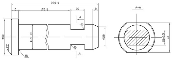
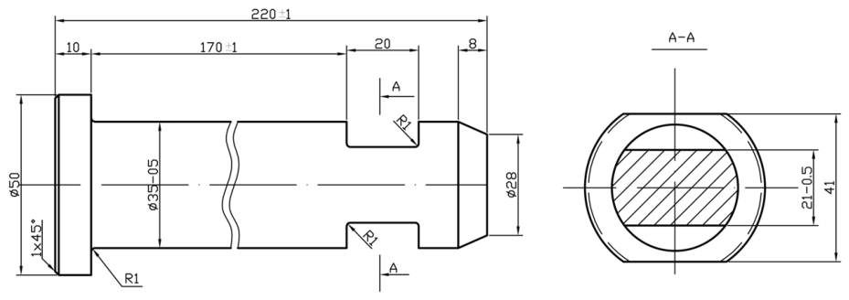
The experimental investigations were carried out on threadless hinge pins used in railway vehicles equipped with leaf-spring suspension systems. The geometry and the main dimensions of the investigated hinge pin are presented in Figure 1. These components have a cylindrical shape and are characteristic of the design of hinge joints in the spring suspension of railway wagons.
Figure 1.
Geometry and main dimensions of a threadless hinge pin used in the spring suspension of railway wagons.
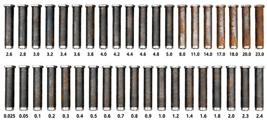
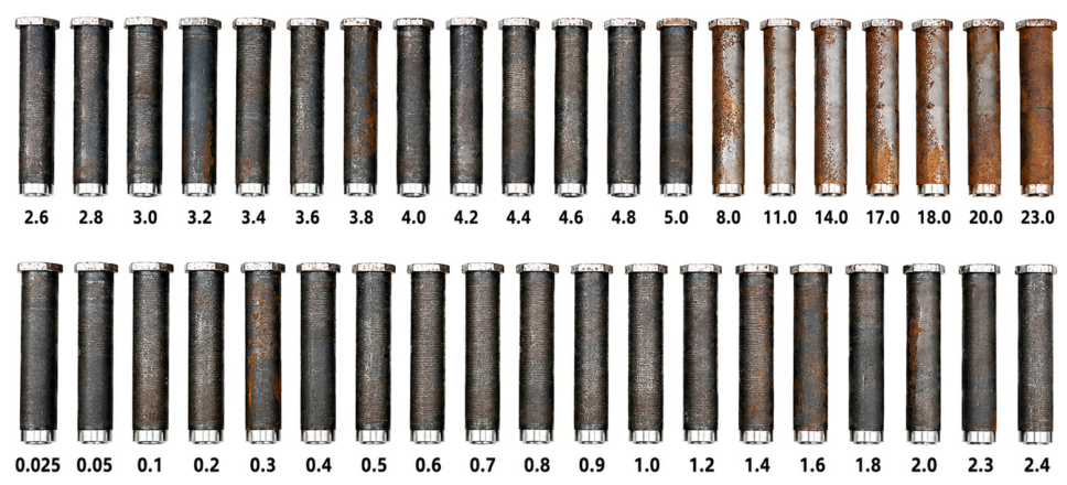
The experimental investigations were carried out on a total of 39 hinge pins made of 42CrMo4 quenched and tempered steel in accordance with EN 10083-3 [28]. To simulate real service defects, erosion notches were introduced in the specimens to imitate fatigue cracks. A single erosion notch with varying depth was produced on 38 of the pins, while one pin contained eight separate erosion notches of different sizes. The depth of the artificially introduced notches ranged from approximately 0.025 to 23 mm. A visualization of the specimens with artificially created defects is presented in Figure 2.
Figure 2.
Hinge pins with artificially introduced erosion notches of different depths used as reference defects for ultrasonic testing.
The notches were manufactured using electrical discharge machining (EDM), which allows the production of defects with high geometric accuracy and good repeatability. The actual depths of the notches were determined using a precision measuring instrument (preseter), enabling subsequent comparison with the results obtained from ultrasonic testing.
In the present study, ultrasonic non-destructive testing was employed, based on the interaction of ultrasonic waves with material defects. The ultrasonic wave frequencies used in the experiments ranged approximately from 5 to 10 MHz, enabling the detection of both surface and internal defects in the investigated components. The tests were performed using a flaw detector with a 64-channel parallel architecture and specialized software Capture version 4.1 (Zetec Inc., Snoqualmie, WA, USA), which enables the application of various ultrasonic inspection techniques and signal processing methods.
During the experimental investigations, a phased array ultrasonic probe with a central frequency of 10 MHz was used. The probe consists of 64 active elements and has an active area of 19.2 mm2. The selection of this probe was determined by the need for high spatial resolution and good sensitivity for detecting small defects. The combination of high frequency and a multi-element structure allows efficient focusing of the ultrasonic beam and precise localization of defects in the investigated hinge pins.
In the experimental study, three main ultrasonic scanning techniques were employed:
- PAUT (Phased Array Ultrasonic Testing);
- FMC/TFM (Full Matrix Capture/Total Focusing Method);
- FMC/PCI (Full Matrix Capture/Phase Coherent Imaging).
The experimental tests were performed using an immersion ultrasonic method, in which the propagation medium of the ultrasonic waves is a liquid. This approach provides stable acoustic coupling between the transducer and the inspected component, which is particularly important for elements with complex geometry such as hinge pins. In addition, the water medium enables more precise positioning of the transducer and improves the quality of the acquired signals.
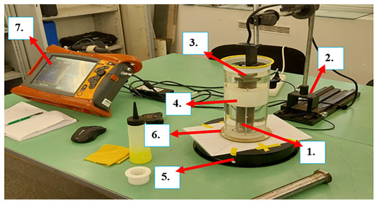
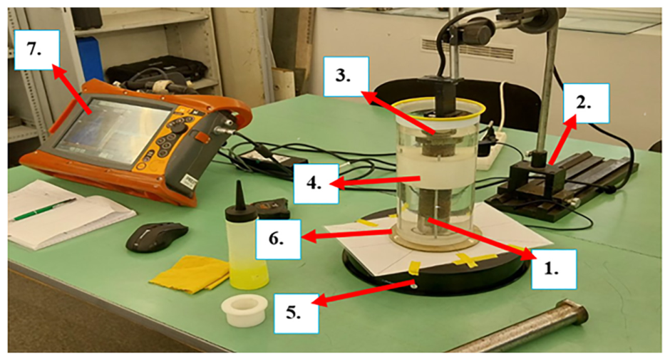
The experimental setup used for conducting the ultrasonic investigations is presented in Figure 3. It includes an immersion ultrasonic testing system consisting of the inspected specimen, an ultrasonic transducer, a fixture for positioning the component, and equipment for signal acquisition and processing.
Figure 3.
Experimental setup for ultrasonic testing of a hinge pin: (1) test specimen; (2) probe positioning stand; (3) ultrasonic probe; (4) specimen holder; (5) electric rotary platform; (6) cylindrical water tank (immersion medium); (7) ultrasonic flaw detector.
The ultrasonic transducer was positioned above the specimen using an adjustable stand, allowing precise orientation of the ultrasonic beam toward the inspected area. During the experiment, the specimen was mounted on an electric rotating platform that ensured uniform rotation of the component and enabled scanning of its entire surface.
Ultrasonic pulses were generated by the flaw detector and introduced into the material through the transducer. The signals reflected from internal or surface defects were received by the same transducer and subsequently processed using specialized software. The scanning of the specimen was performed sequentially using the PAUT, FMC/TFM, and FMC/PCI techniques, allowing a comparative evaluation of the capabilities of the different methods for defect detection and sizing.
The sizing of the detected defects was carried out using the widely applied 6 dB drop method, which is based on determining the width of the indication when the signal amplitude decreases by 6 dB relative to the maximum value. To evaluate the reliability of the applied techniques, the Probability of Detection (POD) approach was used, which represents a quantitative measure of the capability of a non-destructive testing method to detect defects of a given size. The POD analysis was performed using the POD module integrated in CIVA NDE Simulation Software, version 2023 (EXTENDE, Massy, France) as well as the statistical package MIL-HDBK-1823A POD Software, version 5.0 (U.S. Air Force, Wright-Patterson AFB, OH, USA).
The obtained experimental data allow a comparative evaluation of the sensitivity and accuracy of the applied non-destructive testing techniques for the detection and quantitative characterization of defects in hinge pins.
3. Results and Discussion
To evaluate the effectiveness of the applied ultrasonic scanning techniques, a Hit/Miss analysis was performed, which represents a statistical method for determining the probability of detecting defects of different sizes. In this approach, the results of the ultrasonic inspection are classified as either “Hit” (detected defect) or “Miss” (undetected defect), depending on whether the corresponding notch was registered by the applied inspection method.
In the present study, the Hit/Miss analysis was used to evaluate the capability of the PAUT, FMC/TFM, and FMC/PCI techniques for detecting artificially introduced erosion notches simulating fatigue cracks. The defect sizes ranged from 0.025 to 23 mm. The selected range corresponds to the typical dimensions of initiating and propagating fatigue cracks in hinge pins occurring during the operation of railway vehicles, as well as to the sensitivity limits of the applied ultrasonic non-destructive testing methods.
Based on the conducted experimental investigations and the results of the Hit/Miss analysis, the Probability of Detection (POD) was determined for each of the applied ultrasonic scanning techniques. The main parameter used for comparing the effectiveness of the methods is a90/95, which represents the minimum defect size that can be detected with 90% probability at a 95% confidence level.
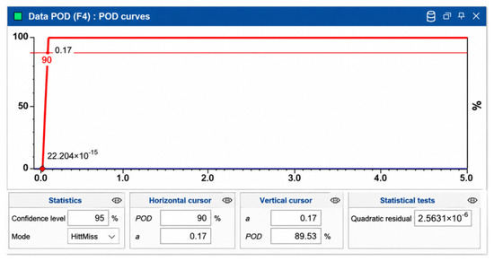
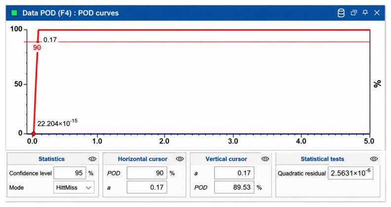
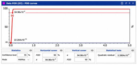
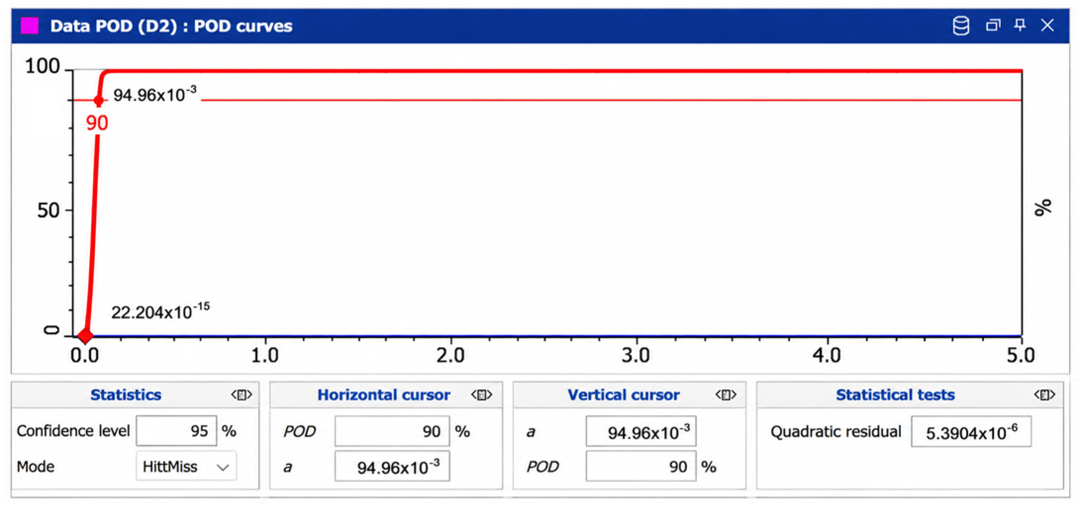
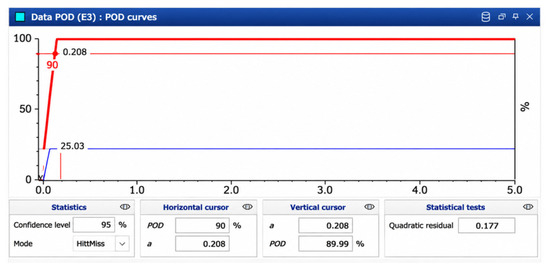
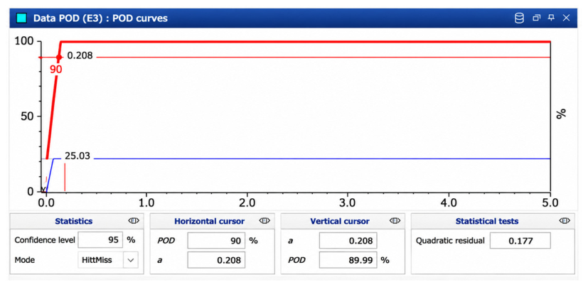
The results of the analysis are presented in both tabular (Table 1) and graphical form (Figure 4, Figure 5 and Figure 6).
Table 1.
a90/95 values for the different ultrasonic scanning techniques.
Figure 4.
Hit/Miss analysis results for the PAUT technique.
Figure 5.
Hit/Miss analysis results for the FMC/TFM technique.
Figure 6.
Hit/Miss analysis results for the FMC/PCI technique.
The analysis of the presented results shows that the probability of defect detection increases with increasing defect size. For the smallest defects, cases of non-detection were observed, which can be attributed to the low amplitude of the reflected ultrasonic signal and an unfavorable signal-to-noise ratio.
The graphical relationships presented in Figure 4, Figure 5 and Figure 6 illustrate the results of the Hit/Miss analysis for the different scanning techniques.
The analysis of the obtained results reveals significant differences in the sensitivity of the applied methods. The lowest value of the a90/95 parameter was obtained when using the FMC/TFM method, indicating that this technique enables the detection of smaller defects compared with the other methods. This is due to the capability for synthetic focusing of the signal at any point within the inspected region, which leads to improved spatial resolution and an increased signal-to-noise ratio.
The PAUT method demonstrates intermediate sensitivity, with a value of a90/95 = 0.17 mm, indicating that defects larger than this value can be detected with a high probability. In contrast, the FMC/PCI method resulted in a higher value of the a90/95 parameter, indicating lower sensitivity compared with the FMC/TFM method for detecting small defects.
The obtained results confirm that techniques based on full matrix capture of signals can provide better capabilities for detecting small defects compared with conventional ultrasonic testing methods. This makes them particularly suitable for the inspection of critical structural components in railway transport, where the early detection of fatigue cracks is essential for safe operation.
In addition to evaluating the probability of defect detection, an analysis of the defect sizing accuracy was also performed. The dimensions of the detected defects were determined using the 6 dB drop method, which is widely applied in non-destructive testing practice. This method provides high repeatability of results and good comparability between measurements, particularly for defects with well-defined reflective characteristics, such as erosion notches.
After opening the recorded file containing the test results, the sizing of the indications using the fixed-level method was performed according to the following procedure:
- The position of the indication corresponding to the notch with the maximum signal amplitude is determined using the cursor. At this position, the corresponding A-scan image is displayed.
- The maximum signal amplitude is adjusted to 80% of the screen height by regulating the input gain of the ultrasonic system (in dB).
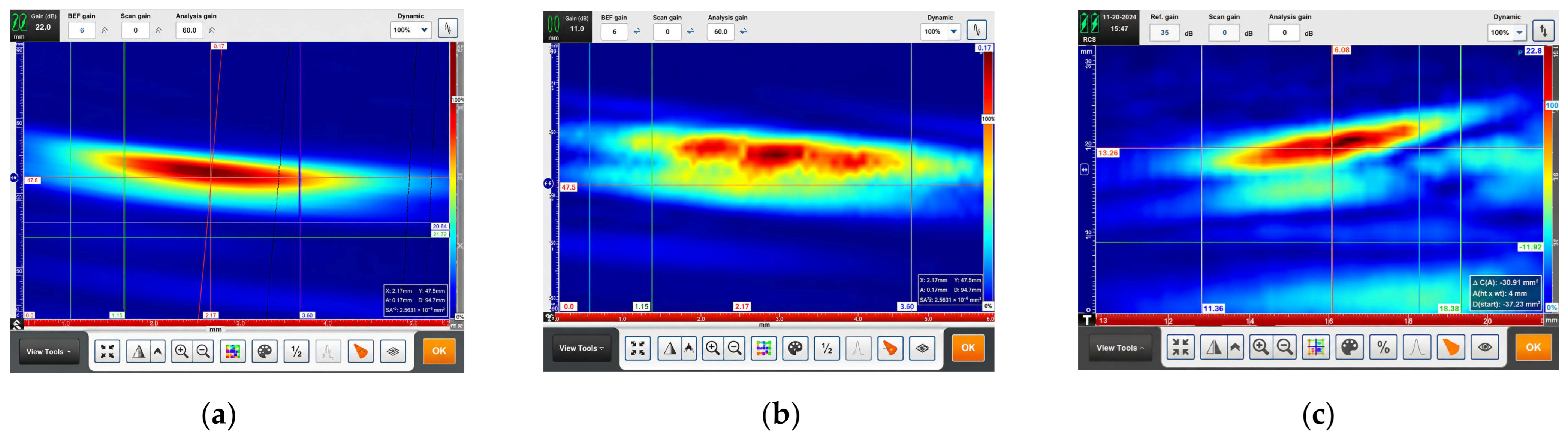
- Using the zoom function, the visualization of the corresponding indication is enlarged, enabling more precise determination of the defect dimensions (Figure 7).
- The width of the indication is measured using the cursors at a level corresponding to 40% of the screen height, in the direction of its maximum extension.
Figure 7.
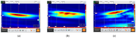
Ultrasonic images of a defect obtained using different ultrasonic scanning techniques: (a) PAUT; (b) FMC/TFM; (c) FMC/PCI.
The obtained values are used to determine the equivalent defect size and to compare it with the actual dimensions of the artificially introduced notches.
Examples of indication sizing using the 6 dB method for the different scanning techniques are presented in Figure 7.
The ultrasonic images presented in Figure 7 illustrate the visualization of the indication from the artificially introduced defect when different scanning techniques are applied.
When using the PAUT technique (Figure 7a), the defect is visualized as a clearly defined region with increased signal amplitude, represented by an intense red–yellow area. The indication is well localized and characterized by clearly defined boundaries, which facilitates interpretation and enables precise determination of the defect size. The resulting image exhibits good contrast between the defect and the surrounding region.
When the FMC/TFM technique is applied (Figure 7b), the defect is also clearly detected; however, the indication is characterized by a more non-uniform amplitude distribution and a wider signal propagation area. As a result, the boundaries of the defect are less clearly defined compared with the image obtained using the PAUT technique.
The image obtained using the FMC/PCI technique (Figure 7c) also enables visualization of the defect, but the indication is characterized by greater spreading and lower signal contrast. Consequently, the boundaries of the defect are more difficult to determine, which may complicate accurate defect sizing.
The qualitative analysis of the obtained images shows that the PAUT technique provides the clearest visualization of the defect among the considered methods. This facilitates the interpretation of the results and the determination of the geometric characteristics of the defect. On the other hand, the FMC/TFM and FMC/PCI methods enable additional signal processing and provide alternative possibilities for the analysis of ultrasonic data.
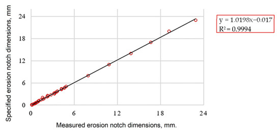
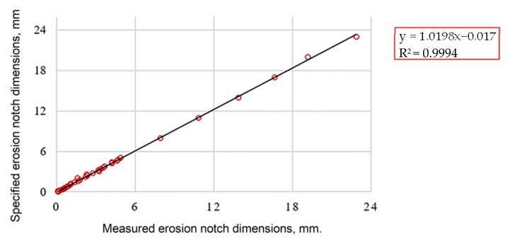
The results of the comparative analysis between the nominal dimensions of the erosion notches and the dimensions measured using a tool presetter are presented in Figure 8. The diagram allows evaluation of the measurement accuracy and provides a reference basis for subsequent comparison with the defect dimensions determined by ultrasonic inspection methods.
Figure 8.
Comparison of the nominal and measured sizes of the erosion notches.
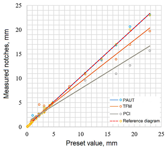
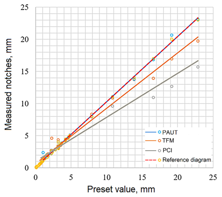
Figure 9 presents a comparison of the sizing results obtained using the PAUT, FMC/TFM, and FMC/PCI techniques with the reference relationship shown in Figure 8.
Figure 9.
Comparison of defect sizing results using the PAUT, FMC/TFM, and FMC/PCI techniques.
The analysis of the obtained results shows that the phased array technique (PAUT) demonstrates the highest degree of agreement with the reference diagram. The measured values are located close to the diagonal line, and the resulting trend relationship practically coincides with it. This indicates high accuracy in the sizing of the erosion notches using the PAUT technique, particularly within the considered size range.
The Total Focusing Method (FMC/TFM) also provides good measurement accuracy; however, for larger notch depths a certain deviation of the results below the reference line can be observed. Nevertheless, the obtained values remain within acceptable limits and can be considered satisfactory for practical application of the method.
The FMC/PCI technique shows the largest deviation of the determined defect sizes from the actual values. The obtained results are systematically located below the diagonal line, which leads to lower sizing accuracy compared with the PAUT and FMC/TFM techniques and limits the applicability of the FMC/PCI method for quantitative analysis. Nevertheless, the technique can still be successfully used for qualitative analysis and defect detection.
In summary, it can be concluded that the PAUT technique provides the highest accuracy in defect sizing, followed by the FMC/TFM method, while the FMC/PCI technique demonstrates lower accuracy in the quantitative determination of notch dimensions.
4. Conclusions
In the present study, a comparative analysis of the capabilities of modern ultrasonic non-destructive testing techniques for the detection and sizing of defects in hinge pins used in railway transport was carried out. Based on the conducted experimental investigations, the following main conclusions can be drawn:
- The applied immersion ultrasonic testing method ensures high repeatability of the results and reduces the influence of the human factor during the scanning of hinge pins.
- The phased array probe with a frequency of 10 MHz, 64 elements, and an active area of 19.2 mm2 proved to be suitable for detecting and sizing artificially introduced fatigue cracks, providing minimal deviation between the actual and measured defect sizes.
- The comparative analysis between the PAUT, FMC/TFM, and FMC/PCI techniques shows that the PAUT technique demonstrates the highest accuracy in defect sizing, the FMC/TFM method provides good accuracy with slight deviations for larger defects, while the FMC/PCI technique exhibits lower accuracy in quantitative analysis but remains suitable for qualitative defect detection.
- The results of the POD analysis indicate that all considered techniques are applicable for reliable inspection of hinge pins, with the FMC/TFM method demonstrating the highest sensitivity for detecting small defects (a90/95 = 0.095 mm).
- The applied 6 dB sizing method provides high repeatability and good comparability of results among the different ultrasonic scanning techniques.
The obtained results confirm that the use of modern ultrasonic non-destructive testing methods enables early detection and accurate sizing of fatigue cracks in critical structural components of railway rolling stock, which significantly contributes to improving the safety and reliability of operation.
Author Contributions
Conceptualization, M.L., Y.M. and S.M.; methodology, Y.M. and S.M.; software, M.L. and S.M.; validation, Y.M., S.M. and M.L.; formal analysis, T.B.; investigation, I.D. and T.B.; resources, I.D.; data curation, I.D. and T.B.; writing—original draft preparation, I.D.; writing—review and editing, M.L. and R.R.; visualization, I.D.; supervision, R.R. and Y.M.; project administration, R.R.; funding acquisition, R.R. and I.D. All authors have read and agreed to the published version of the manuscript.
Funding
This research was funded by the Technical University of Sofia, Branch Plovdiv, under the internal research competition “Engineering Technologies”, project 24PL-I002, entitled “Investigation of the Crack Resistance Parameters of Hinge Pins Made of Alloy Steel with Improved Structure”.
Institutional Review Board Statement
Not applicable.
Informed Consent Statement
Not applicable.
Data Availability Statement
Data are contained within the article.
Acknowledgments
The authors acknowledge the support of the project “Investigation of the crack resistance parameters of hinge pins made of alloy steel with improved structure”, project number 24PL-I002, funded under the competition “Engineering Technologies”. The authors also acknowledge the support provided by the Center of Competence “Smart Mechatronic, Eco- and Energy-Saving Systems and Technologies” for providing access to the laboratory facilities and specialized equipment.
Conflicts of Interest
The authors declare no conflicts of interest.
References
- Mitev, P.; Tashev, A.; Stoyanov, Y. Design and Construction of an Engine Oil Viscosity Meter with Electronic Control. Eng. Proc. 2025, 100, 55. [Google Scholar] [CrossRef] [Scilit]
- Mitev, P. Development of a System for Flexible Feeding of Parts with Robot and Machine Vision. Eng. Proc. 2025, 104, 84. [Google Scholar] [CrossRef] [Scilit]
- Pourheidar, A.; Patriarca, L.; Beretta, S.; Regazzi, D. Investigation of Fatigue Crack Growth in Full-Scale Railway Axles Subjected to Service Load Spectra: Experiments and Predictive Models. Metals 2021, 11, 1427. [Google Scholar] [CrossRef] [Scilit]
- Pan, A.-X.; Wen, C.; Wang, H.; Shi, P.; Bi, Q.; Jia, X.; Tao, P.; Liu, X.; Gong, Y.; Yang, Z.-G. Premature Fatigue Failure Analysis of Axle in Permanent Magnet Direct-Drive Electric Locomotive. Materials 2025, 18, 3747. [Google Scholar] [CrossRef] [Scilit] [PubMed]
- Luo, Y.; Yuan, P.; Li, G.; Yang, B.; Ao, N.; Li, Z.; Wu, Y.; Zhang, G.; Wu, S. Corrosion Fatigue Behavior and Life Prediction of Railway Axle EA4T Alloy Steel with Artificial Indentation. Eng. Fract. Mech. 2024, 296, 109835. [Google Scholar] [CrossRef] [Scilit]
- Zhang, S.; Xie, J.; Jiang, Q.; Zhang, X.; Sun, C.; Hong, Y. Fatigue Crack Growth Behavior in Gradient Microstructure of Hardened Surface Layer for an Axle Steel. Mater. Sci. Eng. A 2017, 700, 66–74. [Google Scholar] [CrossRef] [Scilit]
- Gao, C.; Yu, Z.; Zhang, Y.; Fan, T.; Zhang, B.; Song, H.; Su, H. Experimental Investigation on Fatigue Crack Propagation in Surface-Hardened Layer of High-Speed Train Axles. Crystals 2025, 15, 638. [Google Scholar] [CrossRef] [Scilit]
- Zerbst, U.; Beretta, S.; Köhler, G.; Lawton, A.; Vormwald, M.; Beier, H.T.; Klinger, C.; Černý, I.; Rudlin, J.; Heckel, T.; et al. Safe Life and Damage Tolerance Aspects of Railway Axles—A Review. Eng. Fract. Mech. 2013, 98, 214–271. [Google Scholar] [CrossRef] [Scilit]
- Akama, M. Rolling Contact Fatigue and Wear of Rails and Wheels: A Comprehensive Review. Machines 2025, 13, 970. [Google Scholar] [CrossRef] [Scilit]
- Soleimani, H.; Moavenian, M. Tribological Aspects of Wheel–Rail Contact: A Review of Wear Mechanisms and Effective Factors on Rolling Contact Fatigue. Urban Rail Transit 2017, 3, 227–237. [Google Scholar] [CrossRef] [Scilit]
- Liu, J.; Yang, W.; Wang, Z. Fatigue Crack Propagation Analysis of Rail Surface Under Mixed Initial Crack Patterns. Appl. Sci. 2024, 14, 11454. [Google Scholar] [CrossRef] [Scilit]
- Rodríguez-Arana, B.; San Emeterio, A.; Alvarado, U.; Martínez-Esnaola, J.M.; Nieto, J. Prediction of Rolling Contact Fatigue Behavior in Rails Using Crack Initiation and Growth Models along with Multibody Simulations. Appl. Sci. 2021, 11, 1026. [Google Scholar] [CrossRef] [Scilit]
- Yang, B.; Wang, S.; Li, J.; Ding, X.; Xiao, Q.; Xiao, S. Study on Fatigue Crack Growth in Rail Steel at Numerical and Experimental Approaches. Materials 2023, 16, 2981. [Google Scholar] [CrossRef] [Scilit] [PubMed]
- Nezhad, M.S.; Kabo, E.; Ekberg, A.; Larsson, F. Finite Element Analyses of Rail Head Cracks: Influence of Load Characteristics on Direction and Rate of Rolling Contact Fatigue Crack Growth. Eng. Fract. Mech. 2025, 325, 111322. [Google Scholar] [CrossRef] [Scilit]
- Sung, D.; Hong, S.; Lee, J. Numerical Analysis of the Rail Surface Crack Propagation under Rail Uplift Force: A Parametric Study on Initial Crack Geometry. Eng. Fail. Anal. 2023, 153, 107542. [Google Scholar] [CrossRef] [Scilit]
- Masoudi Nejad, R.; Berto, F. Fatigue Fracture and Fatigue Life Assessment of Railway Wheel Using Non-Linear Model for Fatigue Crack Growth. Int. J. Fatigue 2021, 153, 106516. [Google Scholar] [CrossRef] [Scilit]
- Papaelias, M.; Roberts, C.; Davis, C.L. A Review on Non-Destructive Evaluation of Rails: State-of-the-Art and Future Development. Proc. Inst. Mech. Eng. Part F J. Rail Rapid Transit 2008, 222, 367–384. [Google Scholar] [CrossRef] [Scilit]
- Hu, H.W.; Li, X.B.; Wang, X.H.; Shao, Y.M. Automatic Ultrasonic Inspection Method of Railway Axle and Its Remaining Life Prediction. Adv. Mater. Res. 2011, 213, 291–296. [Google Scholar] [CrossRef] [Scilit]
- Montinaro, N.; Epasto, G.; Cerniglia, D.; Guglielmino, E. Laser Ultrasonics Inspection for Defect Evaluation on Train Wheel. NDT E Int. 2019, 107, 102145. [Google Scholar] [CrossRef] [Scilit]
- Kwon, S.J.; Seo, J.W.; Choe, J.; Hong, S.K. Fretting Crack Detection of a Railway Axle with a Mounted Wheel Using an Induced Current Potential Drop and Electromagnetic-Field Distribution. J. Mech. Sci. Technol. 2023, 37, 6453–6460. [Google Scholar] [CrossRef] [Scilit]
- Kong, Y.; Bennett, C.J.; Hyde, C.J. A Review of Non-Destructive Testing Techniques for the In-Situ Investigation of Fretting Fatigue Cracks. Mater. Des. 2020, 196, 109093. [Google Scholar] [CrossRef] [Scilit]
- Gomez, M.J.; Castejon, C.; Corral, E.; Cocconcelli, M. Railway Axle Early Fatigue Crack Detection through Condition Monitoring Techniques. Sensors 2023, 23, 6143. [Google Scholar] [CrossRef] [Scilit] [PubMed]
- Wang, R.; Crosbee, D.; Beven, A.; Wang, Z.; Zhen, D. Vibration-Based Detection of Wheel Flat on a High-Speed Train. In Advances in Asset Management and Condition Monitoring; Ball, A., Gelman, L., Rao, B., Eds.; Springer: Cham, Switzerland, 2020; Volume 166. [Google Scholar] [CrossRef] [Scilit]
- Shi, S.; Wu, G.; Chen, H.; Zhang, S. Acoustic Emission Monitoring of Fatigue Crack Growth in Hadfield Steel. Sensors 2023, 23, 6561. [Google Scholar] [CrossRef] [Scilit] [PubMed]
- Krampikowska, A.; Pała, R.; Dzioba, I.; Świt, G. The Use of the Acoustic Emission Method to Identify Crack Growth in 40CrMo Steel. Materials 2019, 12, 2140. [Google Scholar] [CrossRef] [Scilit] [PubMed]
- Toasa Caiza, P.D.; Shiozawa, D.; Ummenhofer, T.; Sakagami, T. Real Time Detection of Fatigue Cracks on Steel Structures by Applying Square Wave Induction. Eng. Fail. Anal. 2024, 166, 108799. [Google Scholar] [CrossRef] [Scilit]
- Tamura, H.; Mizokami, Y.; Oto, T.; Katsuhara, H. Development of Detection System for Fatigue Cracks on Orthotropic Steel Deck Using Infrared Thermography and Inspection Results. Proceedings 2025, 129, 60. [Google Scholar] [CrossRef] [Scilit]
- EN 10083-3:2006; Steels for Quenching and Tempering—Part 3: Technical Delivery Conditions for Alloy Steels. CEN: Brussels, Belgium, 2006.

Disclaimer/Publisher’s Note: The statements, opinions and data contained in all publications are solely those of the individual author(s) and contributor(s) and not of MDPI and/or the editor(s). MDPI and/or the editor(s) disclaim responsibility for any injury to people or property resulting from any ideas, methods, instructions or products referred to in the content. |
© 2026 by the authors. Licensee MDPI, Basel, Switzerland. This article is an open access article distributed under the terms and conditions of the Creative Commons Attribution (CC BY) license.