


Abstract
Boundary Layer Ingestion (BLI) is a propulsion integration concept that improves aircraft efficiency by recovering wake momentum deficit and reducing propulsive power requirements. In this study, a numerical methodology is created to study electrified aft-fuselage BLI on a simplified A320 aircraft model across multiple operating conditions. Three configurations were developed: a baseline aircraft, a cruciform-tail configuration in OpenVSP and CFD simulations performed in ANSYS Fluent 2025 R2 using the Spalart–Allmaras turbulence model. The results demonstrate reduced drag, improved lift-to-drag ratio, and a Power Saving Coefficient (PSC) of approximately 5–14%, highest during cruise, climb, and descent conditions at higher altitudes.
1. Introduction
The aviation sector is rapidly growing, with rising concerns related to emissions and their impact on the environment. Therefore, there is considerable momentum to create more efficient aircraft designs through airframe-propulsor integrated design approaches. Significant attention has recently been directed toward boundary layer ingestion (BLI) as a means of reducing fuel consumption in commercial aviation. Conventional aircraft engines primarily ingest undisturbed freestream air, and normally the slower moving airflow in the boundary layer and the wake behind the aircraft are lost to the engines. Both areas represent regions of low momentum; as such, the energy contained in both the boundary layer and the wake is largely wasted. By locating a propulsor within an aircraft’s wake, BLI seeks to recover some of that wasted energy by enabling the propulsor to ingest low momentum airflow from the wake and re-energize it. Therefore, this allows for a reduction in the total propulsive power required for an aircraft to be maintained in flight.
The benefits of BLI can be understood by relating the simplified thrust expression
to the propulsive power added to accelerate given flow from inlet to exit,
T = ṁ (Vexit − VInlet)
P = ½ × ṁ (VExit2 − VInlet2)
P(V) = (T2/2 ρ A V) + T V
For constant thrust, lower inlet velocity reduces the required propulsive power. Since BLI ingests lower momentum wake flow, it reduces the overall propulsive power required while maintaining similar thrust.
Previous studies on NASA’s STARC-ABL configuration [1,2,3] demonstrated that aft fuselage BLI can significantly improve propulsive efficiency and reduce fuel burn. Other studies [4,5] developed analytical and CFD-based methodologies for evaluating BLI performance, while some [6] explored possible benefits, constraints and compromises of aircraft electrification. Moirou et al. [7] provided a holistic summary of BLI technology by linking together current knowledge with a common structure (theoretical performance assessments, modelling methods, and the feedback process for implementing this technology).
Although previous research has shown that BLI can be used to improve fuel efficiency and reduce gas turbine engine fuel consumption, most studies focus on ideal cruise conditions and isolated propulsor analyses. Limited work has been conducted to evaluate BLI performance across multiple flight phases and off-design conditions. Therefore, this study aims to address this gap through the evaluation of electrified aft-fuselage BLI across multiple flight conditions.
2. Materials and Methods
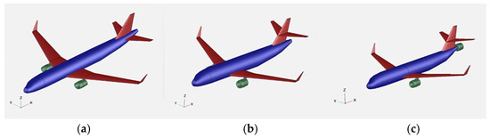
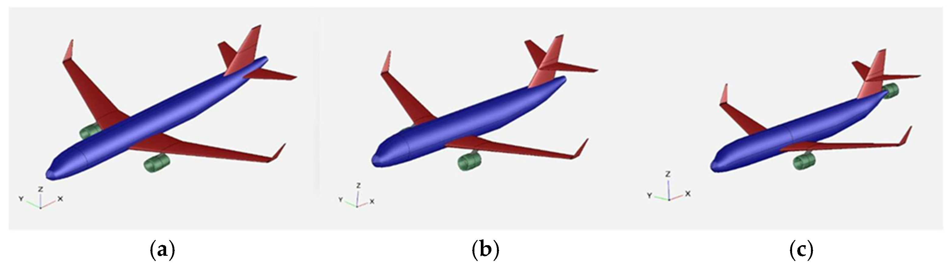
A numerical methodology using CFD was developed to evaluate electrified aft-fuselage Boundary Layer Ingestion (BLI) across multiple flight conditions. Three aircraft configurations were analyzed: a baseline configuration, a cruciform-tail configuration to reduce tail interference with BLI flow, and an aft-fuselage BLI propulsor configuration, as seen in Figure 1.
Figure 1.
(a) Baseline configuration; (b) Cruciform-tail configuration; (c) BLI propulsor configuration.
2.1. Geometry Development
The baseline geometry was developed using publicly available data for the Airbus A320, incorporating available dimensions while estimating missing geometric parameters. The A320 was selected due to the dominance of narrowbody aircraft, making up around 60% of the global commercial fleet, particularly Airbus A320 and Boeing 737 families, which together represent over 90% of total narrowbody aircraft sold [8]. These factors motivated the selection of the A320 as the reference aircraft for this study. Due to the proprietary nature of detailed aircraft design data, particularly wing profiles and high-fidelity geometric features, the present model is not intended to represent an exact replica of the Airbus A320, but rather serve as a simplified narrowbody configuration. The aircraft geometry was developed in OpenVSP. The model has an overall length of 37.57 m, a projected wingspan of 35.8 m, and a resulting wing area of 122.84 m2. In the absence of proprietary airfoil data, the NASA SC(2)-0414 airfoil was selected as a representative supercritical airfoil for a simplified narrowbody aircraft model. Consequently, the present model should not be interpreted as an exact Airbus A320 representation, and the reported aerodynamic and PSC values should rather be considered representative of a simplified narrowbody configuration. The propulsion system was based on the CFM56-5B engine, with an engine nacelle diameter of 1.83 m and an overall engine length of 2.6 m. These parameters were maintained consistently across all three configurations apart from the modified sections.
2.2. Computational Domain and Meshing
An enclosure was created around the aircraft with sufficient dimensions to minimize boundary interference effects during simulation. Symmetry was applied along the longitudinal axis to reduce computational cost and overall cell count. A body of influence (BOI) region was introduced to improve mesh refinement near the aircraft and within the wake region without excessively increasing cell count. Engine sub-domains were created within the primary domain and connected to the enclosure to facilitate continuous flow interaction between the freestream and propulsor. An unstructured mesh was generated with local surface refinement of 0.1 m applied to all aircraft surfaces. Structured inflation layers were used to resolve near-wall flow behaviour. A first inflation layer height of 0.001 m was used, producing average Y+ values in the range of 70–90. Standard wall functions were employed along with the Spalart–Allmaras turbulence model. While a lower Y+ value could improve prediction of the boundary layer profile, the present resolution was considered sufficient for the comparative analysis of BLI performance across configurations. A mesh independence study was performed and subsequently a mesh containing approximately 8 million cells was selected for simulation as a balance between the convergence of solution and computational feasibility.
2.3. Solver Setup and Propulsion Modelling
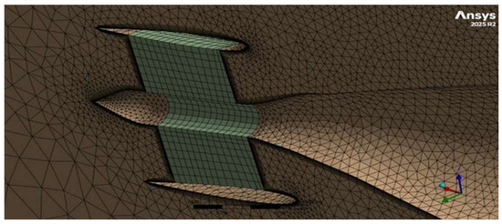
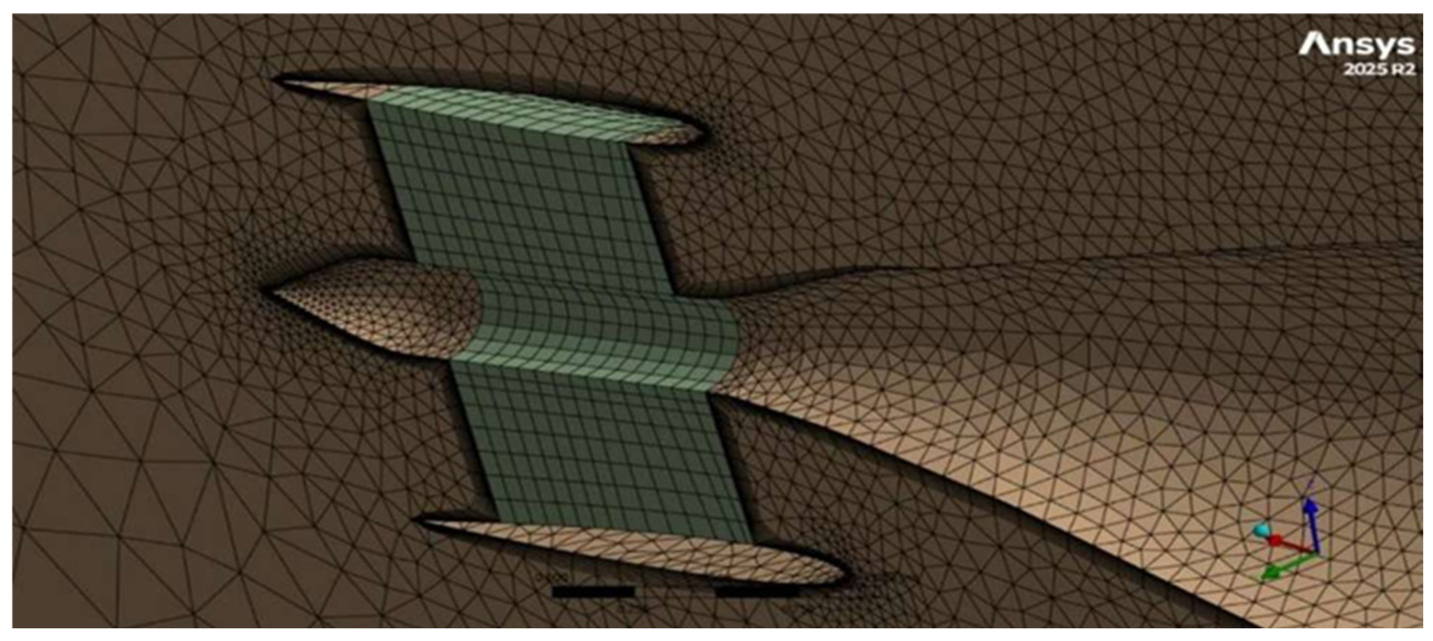
All simulations were performed using ANSYS Fluent, with air as a compressible ideal gas and viscosity defined using Sutherland’s law. The Spalart–Allmaras turbulence model was selected due to its robustness, computational efficiency, and stable convergence characteristics for external aerodynamic flows across multiple operating conditions. Boundary conditions included a velocity inlet, pressure outlet, no-slip wall condition on aircraft surfaces, and a symmetry plane along the longitudinal axis. Simulations were conducted using atmosphere conditions from the International Atmosphere (ISA) model across multiple flight phases. The propulsion system was modelled using engine sub-domains embedded within the primary computational domain, as seen in Figure 2, where propulsion was simulated by using the thrust per unit volume cell zone conditions within the propulsor sub-domains. This approach allowed thrust to be introduced without backflow, which was encountered earlier iterations when attempting to utilize an actuator disc propulsor approach.
Figure 2.
Engine subdomain (green) connected to the primary domain or enclosure (brown).
Thrust distribution was defined such that baseline and cruciform configurations produced 50% thrust from each engine, while the BLI configuration produced 40% thrust from each engine, and the remaining 20% was provided by the aft-fuselage BLI propulsor. This ensured that the total thrust remained constant across all configurations at each flight condition, allowing better understanding of the variation in propulsive power requirements.
2.4. Operating Conditions
The International Standard Atmosphere (ISA) model was utilized to define the respective atmosphere conditions for each flight phase. The use of these parameters ensures that they may be used in a consistent way and allow for the aerodynamic analysis of various flight regimes. The three aircraft configurations were evaluated under take-off, climb, cruise, descent and landing conditions at altitudes of 0 km, 3 km, 11 km, 6 km, and 0 km respectively.
3. Results
The aerodynamic and propulsive performance of the three aircraft configurations was evaluated across multiple flight conditions. Comparative analysis was performed using drag coefficient, lift-to-drag-ratio, and Power Saving Coefficient (PSC) to assess the effectiveness of aft-fuselage BLI.
3.1. Effect of Geometric Modification
The cruciform-tail configuration was analyzed to isolate the effect of geometric modification from the effects of propulsion integration. Results showed a slight increase in drag coefficient and reduction in lift-to-drag ratio when compared to the baseline configuration. The BLI integrated configuration was also studied without active thrust contribution. This resulted in a further increase in drag and reduction in lift-to-drag ratio across all flight conditions. These results indicate that integration of BLI geometry alone provides no aerodynamic benefit and performance improvements are primarily due to ingestion of the wake by the aft-fuselage propulsor.
3.2. Effect of BLI Propulsor
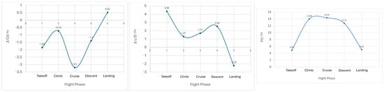
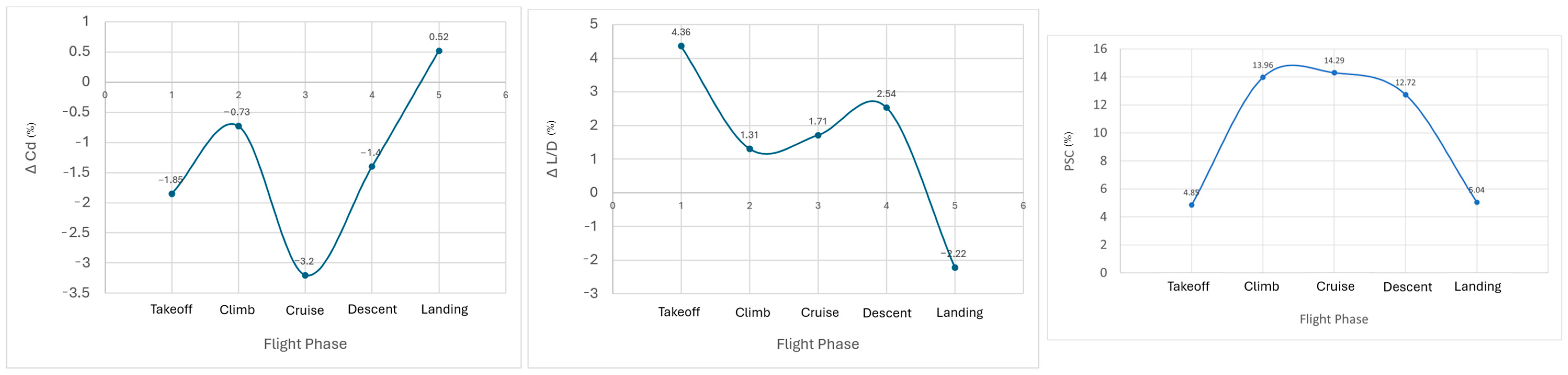
The BLI integrated configuration was analyzed by redistributing the total thrust such that 20% was provided by the aft-fuselage propulsor, while the remaining thrust was contributed by the primary engines. Results showed a reduction in drag coefficient and an improvement in lift-to-drag ratio relative to the baseline configuration across most flight conditions. However, the landing condition showed a slight increase in drag and reduction in lift-to-drag ratio, which was primarily attributed to lower thrust levels and atmospheric conditions near ground altitude. The variation in drag coefficient, lift-to-drag ratio, and Power Saving Coefficient (PSC) can be seen in Figure 3.
Figure 3.
Variation in (a) drag coefficient (Cd); (b) lift-to-drag ratio (L/D); and (c) Power Saving Coefficient (PSC) across flight phases.
The propulsive power added to flow is calculated using Equation (2), and then the Power Saving Coefficient is calculated as
where Pbaseline and Pbli represent the total propulsive power required by the baseline and BLI configurations, respectively.
PSC (%) = ((Pbaseline − Pbli)/Pbaseline) × 100
The Power Saving Coefficient (PSC) values ranged from approximately 5 to 14%, with the highest values obtained during cruise, climb, and descent conditions at higher altitudes. On the other hand, take-off and landing conditions produced lower PSC values of approximately 5%. Table 1 shows a comparison of drag coefficient, lift-to-drag ratio, and Power Saving Coefficient (PSC) across all flight conditions.
Table 1.
Variation in drag coefficient, lift-to-drag ration and PSC across flight phases.
4. Discussion
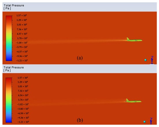
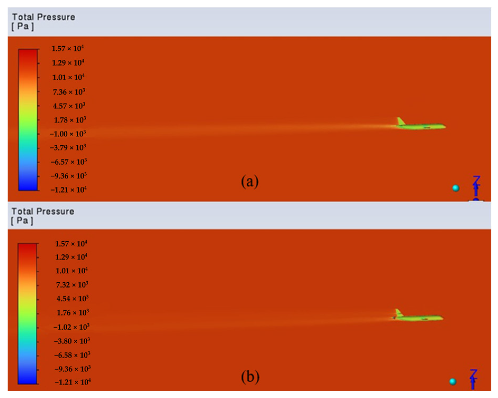
The results demonstrate that aerodynamic benefits are obtained only when the aft-fuselage propulsor actively ingests the low-momentum wake flow. The reduction in drag and improvement in lift-to-drag ratio observed in the BLI integrated configuration are consistent with the theoretical relationship between inlet velocity and propulsive power, as shown in Equation (3). By ingesting lower momentum flow from the aircraft wake, the propulsor requires lower power to generate similar thrust when compared to the conventional baseline configuration. The observed PSC values are also consistent with previous studies on aft-fuselage BLI systems for cruise condition. The reduction in drag can be attributed to the decreased extent of the low-pressure wake region behind the aircraft, as observed in Figure 4. Although the drag reduction is modest, the primary objective was to offset the aerodynamic penalties associated with integrating the aft-fuselage propulsor, which was successfully achieved.
Figure 4.
Low pressure wake comparison between (a) baseline and (b) BLI model.
The variation in PSC across the flight envelope highlights a strong dependence of BLI performance on operating conditions. Cruise, climb, and descent phases produced the highest PSC values due to relatively stable operating conditions and higher altitudes. In contrast, take-off and landing conditions produced lower PSC values, despite take-off having the highest thrust levels out of all conditions. This behaviour is likely influenced by a multitude of factors such as higher angles of attack, lower freestream velocities, and atmospheric conditions which reduce the effectiveness of wake ingestion.
5. Conclusions
This study evaluated electrified aft-fuselage Boundary Layer Ingestion (BLI) using a simplified Airbus A320 configuration across multiple flight conditions using CFD simulations. Results showed that ingestion of low momentum wake by the aft-fuselage propulsor reduced drag, improved lift-to-drag ratio, and reduced required propulsive power across most flight conditions. The calculated Power Saving Coefficient (PSC) ranged from approximately 5 to 14%, with the highest values observed during cruise, climb, and descent conditions at higher altitudes. These findings demonstrate the potential of BLI to improve aerodynamic and propulsive efficiency across a wider range of operating conditions beyond cruise flight. Overall, the numerical methodology used in this study provides a practical approach for evaluating aero-propulsive integration effects under different operating conditions. Future work can include higher-fidelity modelling with greater computational resources, improved aero-propulsive structure, and experimental validation of the present methodology.
Author Contributions
Conceptualization, S.M., N.S.N. and P.V.; methodology, S.M. and N.S.N.; software, S.M. and N.S.N.; validation, S.M., N.S.N. and P.V.; formal analysis, S.M. and N.S.N.; investigation, S.M. and N.S.N.; data curation, S.M. and N.S.N.; writing, original draft preparation, N.S.N.; writing, review and editing, S.M., N.S.N. and P.V.; visualization, supervision, P.V.; project administration, P.V.; funding acquisition, Not applicable. All authors have read and agreed to the published version of the manuscript.
Funding
This research received no external funding.
Institutional Review Board Statement
Not applicable.
Informed Consent Statement
Not applicable.
Data Availability Statement
The raw data supporting the conclusions of this article will be made available by the authors on request.
Conflicts of Interest
The authors declare no conflicts of interest.
Abbreviations
The following abbreviations are used in this manuscript:
| BLI | Boundary Layer Ingestion |
| CFD | Computational Fluid Dynamics |
| PSC | Power Saving Coefficient |
| ISA | International Standard Atmosphere |
References
- Welstead, J.; Felder, J.; Guynn, M.; Haller, B.; Tong, M.; Jones, S.; Ordaz, I.; Quinlan, J.; Mason, B. Overview of the NASA STARC-ABL (Rev. B) Advanced Concept. In Proceedings of the One Boeing NASA Electric Aircraft Workshop, Washington, DC, USA, 22 March 2017. [Google Scholar]
- Gray, J.S.; Mader, C.A.; Kenway, G.K.W.; Martins, J.R.R.A. Coupled Aeropropulsive Optimization of a Three-Dimensional Boundary-Layer Ingestion Propulsor Considering Inlet Distortion. J. Aircr. 2020, 57, 1014–1025. [Google Scholar] [CrossRef] [Scilit]
- Yildirim, A.; Gray, J.S.; Mader, C.A.; Martins, J.R.R.A. Boundary-Layer Ingestion Benefit for the STARC-ABL Concept. J. Aircr. 2022, 59, 896–911. [Google Scholar] [CrossRef] [Scilit]
- Goldberg, C.; Nalianda, D.; MacManus, D.; Pilidis, P.; Felder, J. Method for Simulating the Performance of a Boundary Layer Ingesting Propulsion System at Design and Off-Design. Aerosp. Sci. Technol. 2018, 78, 312–319. [Google Scholar] [CrossRef] [Scilit]
- Lv, P.; Rao, A.G.; Ragni, D.; Veldhuis, L. Performance Analysis of Wake and Boundary-Layer Ingestion for Aircraft Design. J. Aircr. 2016, 53, 1517–1526. [Google Scholar] [CrossRef] [Scilit]
- Kruger, M. The Challenges and Potential Benefits of Electrified Propulsion for Aircraft; University of Southern California: Los Angeles, CA, USA, 2022. [Google Scholar] [CrossRef]
- Moirou, N.G.M.; Sanders, D.S.; Laskaridis, P. Advancements and Prospects of Boundary Layer Ingestion Propulsion Concepts. Prog. Aerosp. Sci. 2023, 138, 100897. [Google Scholar] [CrossRef] [Scilit]
- International Air Transport Association (IATA). The Global Commercial Aircraft Fleet. Available online: https://www.iata.org/en/publications/economics/reports/the-global-commercial-aircraft-fleet/ (accessed on 11 August 2025).

Disclaimer/Publisher’s Note: The statements, opinions and data contained in all publications are solely those of the individual author(s) and contributor(s) and not of MDPI and/or the editor(s). MDPI and/or the editor(s) disclaim responsibility for any injury to people or property resulting from any ideas, methods, instructions or products referred to in the content. |
© 2026 by the authors. Licensee MDPI, Basel, Switzerland. This article is an open access article distributed under the terms and conditions of the Creative Commons Attribution (CC BY) license.