


Abstract
Continuous population growth will lead to further expansion and densification of urban environments. In this context, Urban Air Mobility (UAM) has emerged as a new transportation solution through the use of Vertical Take-Off and Landing (VTOL) aircraft, more precisely, configurations such as lift-plus-cruise tilt-rotors. During the conceptual design phase, propeller design methodologies commonly reported in the literature rely on vortex-based approaches or actuator disk theory. However, the accuracy of these methods strongly depends on the inflow angle and operating conditions. This paper introduces an analytical model to predict propeller thrust at a 90° inflow angle (edgewise flight), based on a correction of the thrust under axial flight conditions and the propeller geometry evaluated at 75% span. The approach relies on local velocity and angle of attack estimations derived from classical Blade Element Momentum Theory (BEMT) with an additional correction to account for stall effects at high angles of attack. This capability is particularly relevant for modeling lift-plus-cruise tilt-rotor configurations cruise phase during early design stages while maintaining minimal computational cost. The proposed model is validated against wind tunnel measurements for several propellers tested at different global pitch angles, varying from 0 m/s to 9.1 m/s of windspeed and 1300 to 6200 rpms, demonstrating the applicability of the developed formulation for blades with twist angles up to 16°.
1. Introduction
Future projections indicate that sustained population growth will drive the expansion and densification of urban areas, intensifying transportation demands and associated challenges.
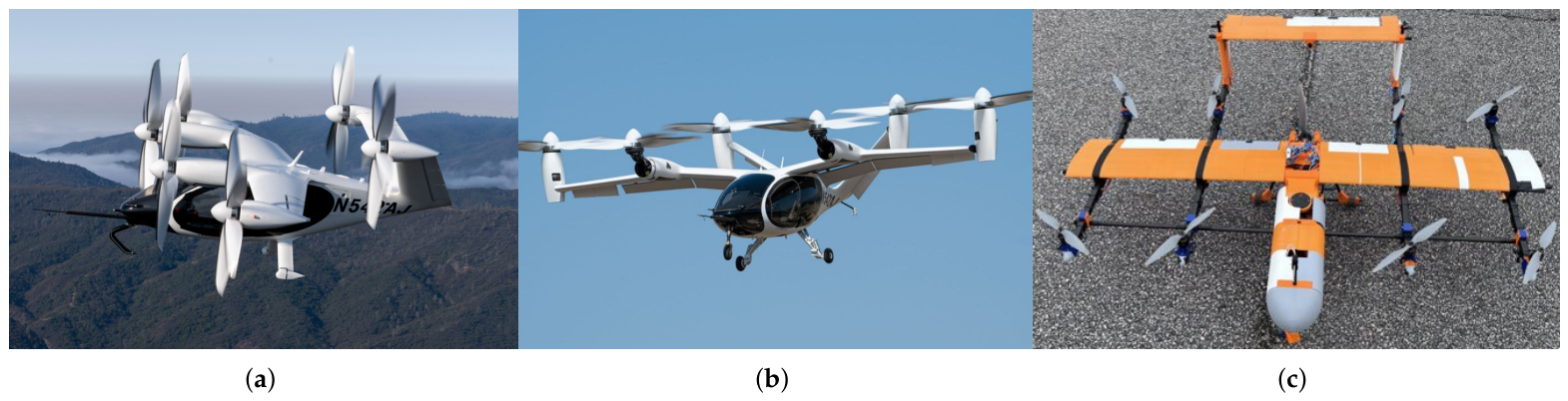
In this context, Urban Air Mobility (UAM) has emerged as a promising alternative, enabling novel intra- and inter-urban transport solutions through the deployment of Vertical Take-Off and Landing (VTOL) aircraft, including lift-plus-cruise tilt-rotor configurations. An example of these new configuration can be seen in Figure 1.
During the conceptual design phase of such vehicles, propeller design methodologies commonly reported in the literature typically rely on vortex-based approaches or actuator disk theory to define primary propeller characteristics [1,2,3]. Once these requirements are established, blade geometry is generally derived using blade element theory.
However, the accuracy of these approaches is strongly influenced by inflow angle and operating conditions, with discrepancies increasing at higher inflow angles and advance ratios. In lift-plus-cruise tilt-rotor aircraft operating in cruise, the inflow conditions experienced by vertically oriented rotors can lead to inconsistencies when higher-fidelity models are applied in later design stages, ultimately increasing development time and cost due to additional design iterations.
Figure 1.
Joby Aviation’s eVTOL UAM full scale behicle operating in (a) axial flight and (b) edgewise flight, (adapted from [4]), and (c) LPC-03-s subscale lift-plus-cruise model [5].
To address these limitations, several higher-fidelity numerical approaches have been proposed, including Computational Fluid Dynamics (CFD) and extensions of classical Blade Element Momentum Theory (BEMT) [6]. These extensions incorporate induced-velocity corrections or rely on experimentally derived coefficients to improve predictive accuracy under off-design conditions. Additionally, empirical and semi-empirical formulations based on axial inflow experiments have been developed to approximate the effect of inflow angle on thrust coefficients [7].
From an experimental perspective, multiple wind tunnel studies have investigated propeller performance under varying inflow angles [8,9]. These works consistently show that the accuracy of BEM-based predictions decreases with increasing advance ratio when compared to experimental data.
Despite these efforts, there remains a lack of computationally efficient methods capable of accurately predicting propeller thrust under extreme inflow angle conditions.
To address this gap, the present study reports a wind tunnel experimental campaign focused on characterizing propeller thrust performance. Two propeller geometries with different pitch angles are evaluated across a broad range of operating conditions. The primary objective is to develop an analytical formulation capable of predicting the thrust coefficient for any advance ratio at a 90° inflow angle (flow parallel to the plane of rotation, reported in the literature, and further referred to, as edgewise flight [10,11,12]), based on thrust coefficient data obtained under perpendicular inflow conditions. This approach aims to improve the accuracy of conceptual design predictions while reducing the need for iterative refinement, thereby lowering both computational cost and development time. This work extends the authors’ previous contribution presented at IOCAE 2026 [13].
The remainder of the paper is structured as follows: Section 2 describes the experimental setup and operating conditions; Section 3.1 presents the proposed model; Section 3.2 details its validation; and Section 4 discusses the results.
2. Materials and Methods
This section describes the propellers used, the experimental facilities and the test matrix followed during the experimental campaign.
The study considered two propeller geometries, a two-bladed commercial propeller XOAR PJN [14] and a two-bladed propeller derived from the APC-96 model [15] (hereafter referred to as “Casalino” model, after its author). All propellers were two-bladed, scaled to a diameter of 30 cm, and fabricated via Stereolithography using a FormLabs Forms 3L printer with Grey V4 material and a layer height of 0.025 mm. For each geometry, three variants were manufactured with a ±5° pitch variation, yielding a total of six different propeller models.
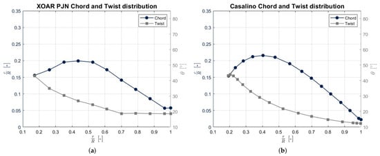
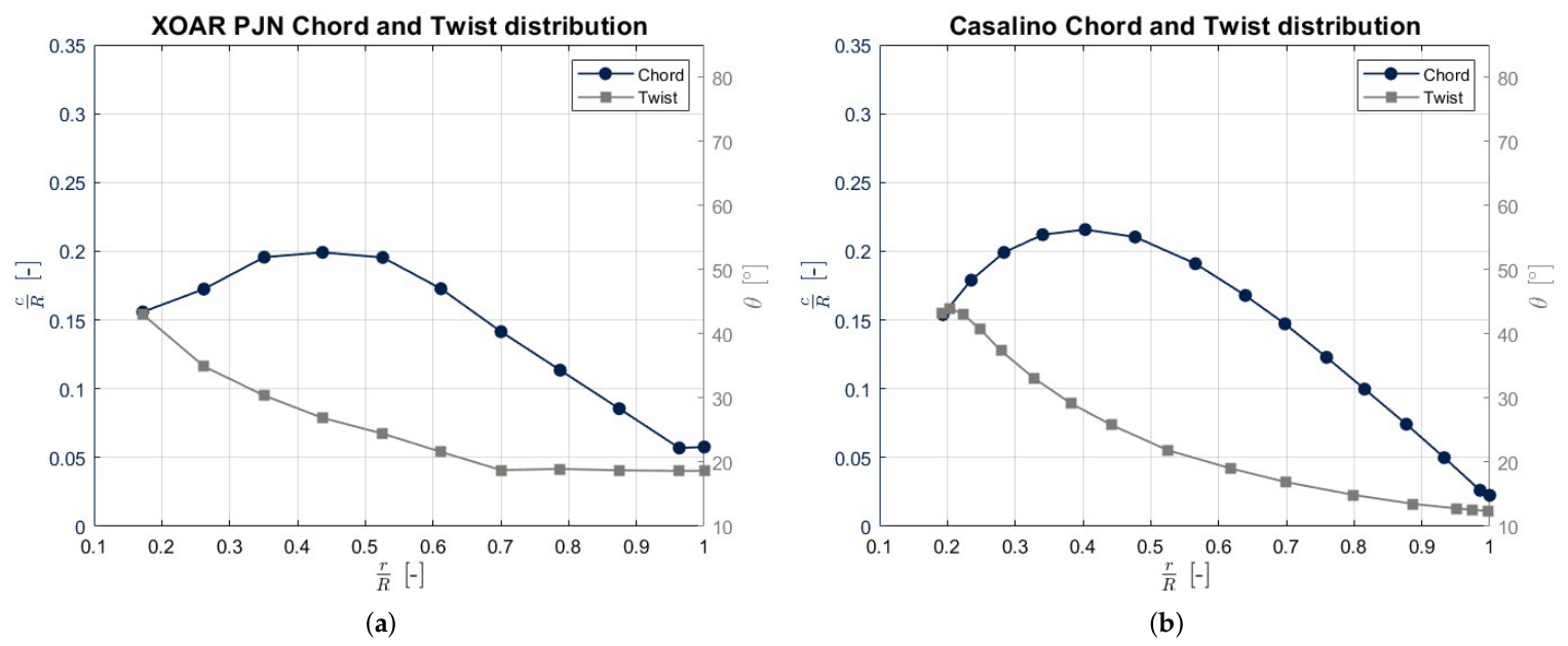
The propellers twist and chord distribution can be found in Figure 2.
Figure 2.
(a) XOAR PJN propeller chord and twist distribution [14]. (b) Casalino propeller chord and twist distribution [15].
The experiments were conducted in the Research Institute Clean Mobility & Thermofluids “Profesor Francisco Payri” wind tunnel [16], an open loop wind tunnel with a square test section of 2.8 m side and a 22 m long working section with chamfered corners.
A test bench was designed to evaluate propeller performance under different operation conditions, including different wind and rotational speeds, global pitch and inflow angle. The propeller is driven by an electric motor (T-Motor MN6007II Antigravity). To measure torque and thrust, the propeller is attached to three different load cells (WIKA F4802).
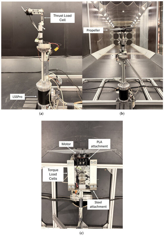
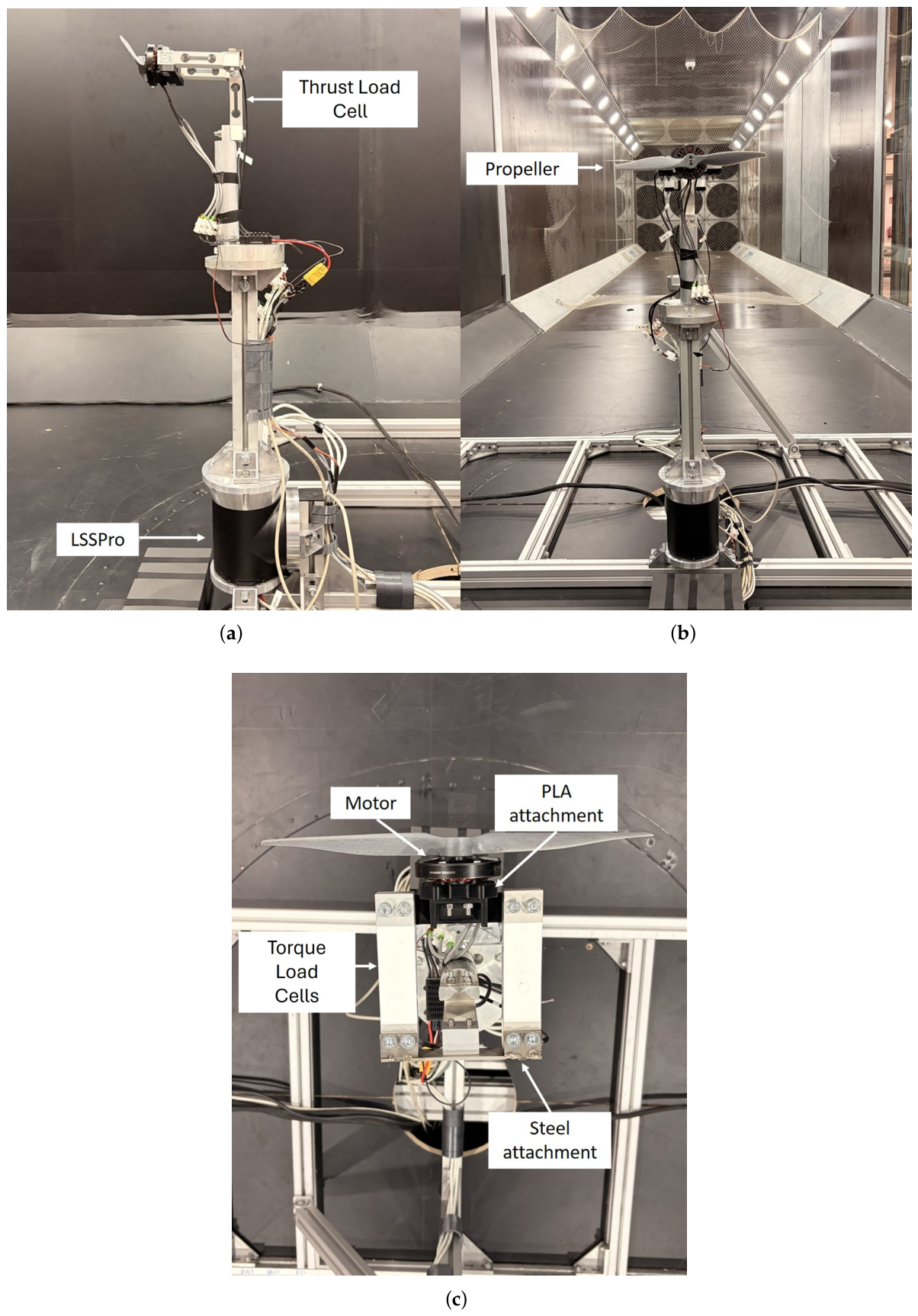
The measurement system is mounted on steel beams and connected to a smart LSSPro servo, which controls the inflow angle by rotating the test bench to adjust the propeller’s position. The entire assembly is also anchored to the wind tunnel floor using additional steel beams. The final experimental set up can be seen in Figure 3.
Figure 3.
(a) Test bench side view showing the smart servo and the thrust measuring load cell. (b) Test bench front view showing the propeller (c) Test bench top view showing torque load cells, the electric motor and the load cell attachments.
The experimental campaign involved performing rotational speed sweeps at various wind speeds and inflow angles for each propeller and its pitch variations. The test matrix is summarized in Table 1. Rotational speed was controlled by adjusting the motor power in fractions of the total output, with ten operational points ranging from 20% to 80% of total power, corresponding approximately to 1300–6200 rpm. Wind speed was regulated by varying the wind tunnel fan frequency, with seven different settings tested (0 Hz, 6 Hz, 8 Hz, 10 Hz, 12 Hz, 14 Hz, and 15 Hz), corresponding to 0–9.1 m/s. This combination allows measuring propeller thrust in advance ratio values between 0 and 0.77 and Reynolds numbers between about 500,000 and 2 millions. The inflow angle was set via servo position. For each test, a specific propeller and pitch angle were selected, the wind speed and inflow angle were imposed, and a rotational speed sweep was performed while measuring electric power and the different loads perceived by each load cell. Extreme rotational speeds were avoided to ensure propeller structural integrity, and tests at windspeeds above 6.3 m/s were limited to inflow angles up to 45° for the same reason, since previous tests reported several structural damage at the propeller above these limits.
Table 1.
Experimental campaign test matrix scheme.
The load cells were calibrated prior to testing. A baseline measurement without propellers was also conducted to isolate forces originating from the test bench itself, measuring the drag generated by the test bench, which will be then added to the measured values of thrust at each studied windspeed. Measurements were recorded at 20 Hz for a duration of 4 s, and the resulting force at each point was calculated as the mean after removing values that deviated by more than twice the standard deviation.
3. Results and Discussion
This section presents the mathematical model formulated and its subsequent validation through comparison with the experimental data collected.
3.1. Mathematical Model
The primary measured variable is the propeller thrust, non-dimensionalized through the thrust coefficient, defined as in (1):
which is presented as a function of the advance ratio, defined in (2)
The developed model is based on correcting the measured thrust under perpendicular inflow conditions () by accounting for the variations in relative velocity and angle of attack experienced by a representative blade section under edgewise flight ().
The formulation proceeds as follows. First, the required assumptions are established and the adopted coordinate system is defined. The thrust expression derived from Blade Element Momentum Theory (BEMT) serves as the foundation of the model. A correction function is then introduced to account for the effects associated with parallel inflow.
The main assumptions considered in the development of the analytical model are:
- The curve as function of advance ratio are at .
- A representative blade section is located at 75% of the span [17].
- The chord and twist values at 75% of the span are known.
- The lift coefficient is approximated using a flat-plate model.
- The propeller disk is divided according to the number of blades, following a semi-empirical approach [18].
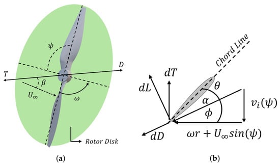
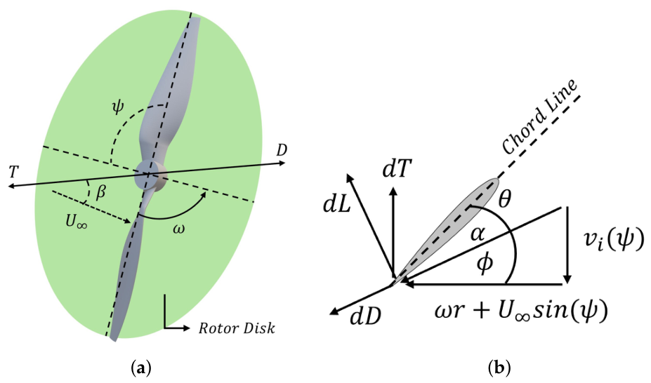
The adopted coordinate system is cylindrical, with its origin located at the propeller center, as shown in Figure 4. The system is defined according to the relative orientation between the propeller and the incoming flow, both referenced to the propeller center. The inflow angle is denoted by , while the rotational speed is represented by .
Figure 4.
(a) Coordinate system used, centered on the propeller center. (b) Velocity triangle and force diagram at .
Focusing on a representative blade section, the velocity components for an inflow angle of , based on BEMT, are illustrated in Figure 4. In this framework, denotes the flow angle, the sectional angle of attack, and the local pitch angle. From Figure 4, the elemental thrust contribution produced by one of the blades can be written as in (3):
Selecting the representative section at , as previously justified, the thrust expression reduces to (4):
where the flow angle is defined as in (5)
The sectional angle of attack is obtained as the difference between the local pitch angle and the flow angle.
Starting from the perpendicular inflow case (), and assuming a flat-plate lift coefficient corrected by the angle of attack [7], the lift at the representative section is expressed as in (6):
while the corresponding drag force is defined in (7):
The total velocity perceived by the blade section, , is given in general form by (9):
The induced velocity is computed as in the work from Dodic et al. [19], and solved using the Matlab r2025b fzero root-finding algorithm, using a 10% of the measured windspeed as an initial guess, as shown in (10):
The thrust under edgewise flight () is then formulated as a correction of the perpendicular inflow thrust as in (11):
In the edgewise flow case, the drag contribution can be neglected, as it is smaller than in axial inflow (no parasitic drag acts along the thrust direction) and is further multiplied by , which remains small.
To obtain the total thrust, the propeller disk is divided into azimuthal sectors according to the number of blades [18]. Any quantity depending on the azimuth angle is therefore averaged as in (12):
where b denotes each blade and B is the total number of blades. For the flow angle , the induced velocity term in the numerator is corrected by dividing it by the number of disk sectors. The final thrust expression, corrected with the mean angle of attack, becomes (13):
3.2. Model Validation
Along this section the calculated values of thrust coefficient are compared to the measured results.
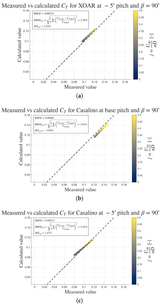
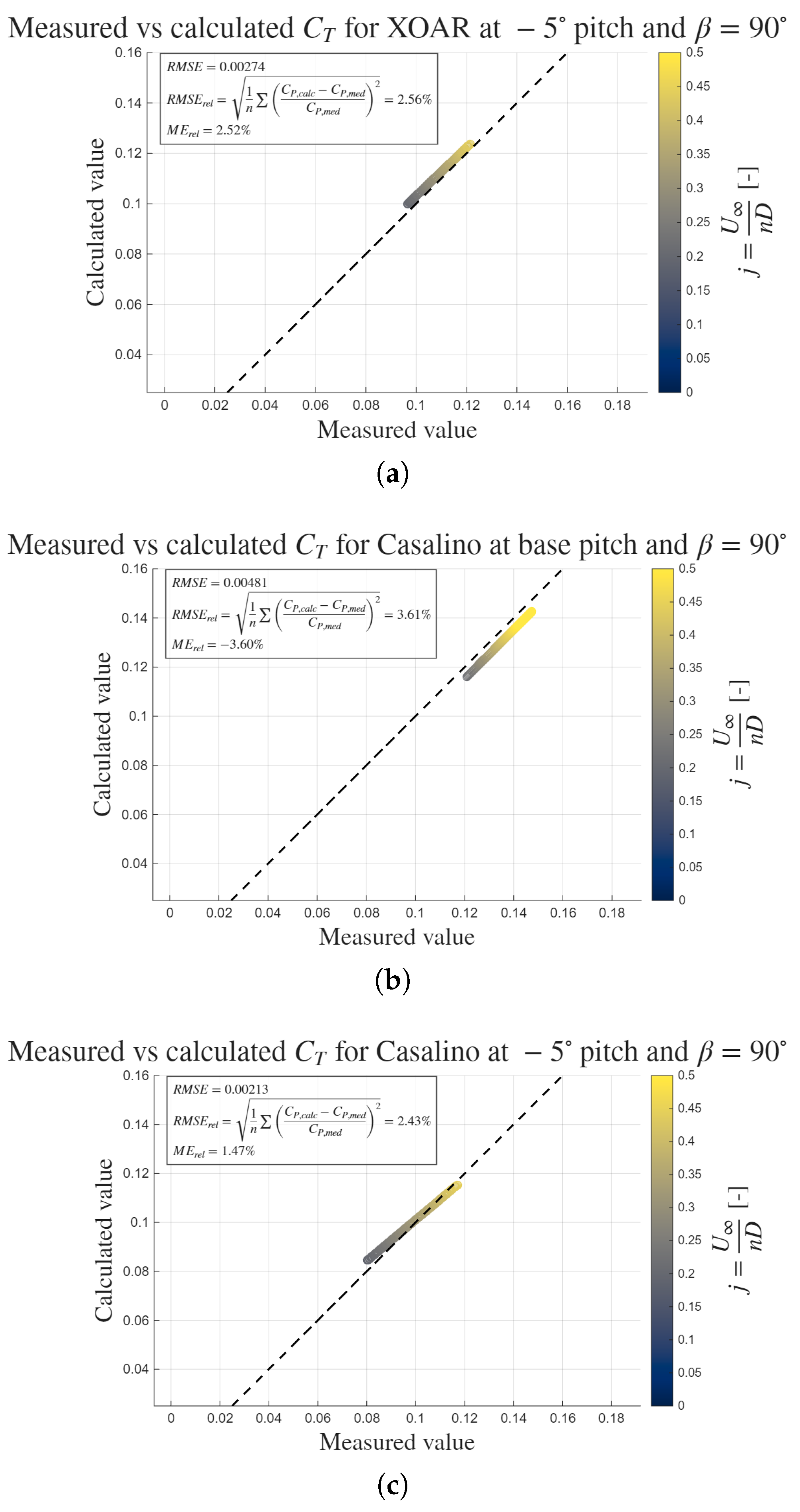
The assumptions done in Section 3.1 have shown a limited validity for propellers with a local pitch at 75% of the span of . Filtering to the studied propellers that fit in that range, the results on thrust coefficient can be seen in Figure 5, a parity plot where the measured values (x axis) are compared to the calculated ones (y axis), together with the ideal case line (dahsed black line) representing y = x.
Figure 5.
(a) XOAR PJN propeller at negative pitch calculated vs. measured thrust coefficient. (b) Casalino propeller at negative pitch calculated vs. measured thrust coefficient. (c) Casalino propeller at base pitch calculated vs. measured thrust coefficient.
As observed, the analytical thrust prediction successfully captures the experimental trends, exhibiting small discrepancies. The maximum point error is 4.97%, corresponding to the Casalino blade at negative pitch and low advance ratio. This error is also associated to the lower values measured. The error metrics reported in Figure 5 provide a quantitative assessment of the agreement between calculated and measured thrust coefficients. The root mean square error (RMSE) quantifies the overall magnitude of the deviations between predicted and experimental values, showing a maximum deviation of 0.00481, which, normalized with respect to the measured values, as indicated by the relative RMSE (RMSErel), implies a 3.61% of error for the Casalino blade at base pitch. Finally, the relative Mean Error (MErel) indicates the average signed deviation, showing a slight underprediction of 3.60% for the Casalino blade at base pitch. In any case, the reported differences between measured and calculated values remains below 5%, proving the applicability of the developed model.
4. Concluding Remarks
This work presents a novel analytical formulation for predicting the thrust of vertical propellers in tilt-rotor lift-plus-cruise configurations operating under cruise conditions, where extreme inflow angles are encountered. The model has been validated against wind tunnel measurements, showing good agreement with experimental trends, with a maximum point deviation of 4.97% and a maximum relative RMSE of of 3.61%.
The proposed formulation successfully captures the underlying physical behavior of the propellers. Its applicability is currently limited to local pitch angles below 16°, which is likely associated with the validity range of the flat-plate lift assumption. Beyond this threshold, three-dimensional stall effects and nonlinear lift behavior become significant, leading to increased prediction errors.
Compared to high-fidelity approaches such as Computational Fluid Dynamics (CFD), the present method offers a computationally efficient alternative. While CFD provides detailed flow-field information, it requires substantial computational resources and longer turnaround times. In contrast, the proposed model enables rapid thrust estimation with minimal computational cost, making it particularly well-suited for early-stage design applications.
Nevertheless, the model has some limitations. Validation has been performed only for two-bladed propellers with moderate pitch angles at relatively low windspeeds. Future work should address its applicability to configurations with a higher number of blades and incorporate improved lift modelling to better capture stall phenomena. Additionally, extending the formulation to predict the power coefficient would further enhance its practical utility.
In summary, the proposed analytical model provides a reliable and low-cost method for estimating propeller thrust under extreme inflow conditions, with sufficient accuracy for preliminary design purposes. Its integration into conceptual design frameworks can facilitate faster evaluation of propeller performance in tilt-rotor lift-plus-cruise systems.
Author Contributions
Conceptualization, N.A.-B.; methodology, N.A.-B., P.V. and L.M.G.-C.; software, N.A.-B.; validation, N.A.-B., P.V. and L.M.G.-C.; resources, L.M.G.-C.; data curation, N.A.-B., P.V. and L.M.G.-C.; writing—original draft preparation, N.A.-B.; writing—review and editing, P.V., J.G.-T. and L.M.G.-C.; visualization, N.A.-B.; supervision, P.V., J.G.-T. and L.M.G.-C.; project administration, L.M.G.-C.; funding acquisition, L.M.G.-C. All authors have read and agreed to the published version of the manuscript.
Funding
This work was developed within the scope of the AURORA project (Grant PID2023-150573OB-I00), funded by MICIU/AEI/10.13039/501100011033 and by ERDF/EU. The work was also partially funded by the Universitat Politècnica de València through Grant FPI-2022-S2-110996.
Institutional Review Board Statement
Not applicable
Informed Consent Statement
Not applicable
Data Availability Statement
All the used data can be found online at https://zenodo.org/records/20111572 (Accessed on 26 June 2026).
Conflicts of Interest
The authors declare no conflicts of interest.
Abbreviations
The following abbreviations are used in this manuscript:
| UAM | Urban Air Mobility |
| CFD | Computational Fluid Dynamics |
| BEMT | Blade Element Momentum Theory |
| VTOL | Vertical Take-Off and Landing |
| RMSE | Root Mean Square Error |
| RMSErel | Relative Root Mean Square Error |
| ME | Mean Error |
| MErel | Relative Mean Error |
References
- Lee, H.; Sengupta, B.; Araghizadeh, M.; Myong, R. Review of vortex methods for rotor aerodynamics and wake dynamics. Adv. Aerodyn. 2022, 4, 20. [Google Scholar] [CrossRef] [Scilit]
- Du, Y.; Liu, Z.; Shen, M.; Wu, J.; Zhang, K.; Jiang, C.; Zhong, J. An Efficient Parametric Modeling, Evaluation and Optimization Strategy for Aerodynamic Configuration Design of eVTOL Aircraft. Aerosp. Res. Commun. 2025, 3, 14986. [Google Scholar] [CrossRef] [Scilit]
- Faraaz, M.; Faizan, A.; Badarinath, M.; Subramaniyan, K.V.; Harursampath, D.; Gupta, R.B. Baseline design of propeller for an evtol aircraft to achieve urban air mobility. In Proceedings of the 2023 IEEE Aerospace Conference; IEEE: Piscataway, NJ, USA, 2023; pp. 1–10. [Google Scholar]
- Thai, A.; Bain, J.; Mikic, G.V.; Stoll, A. Flyover noise computations of the joby aviation aircraft. Horizon 2023, 270, 60. [Google Scholar]
- Comer, A.; Chakraborty, I.; Kovryzhenko, Y.; Taheri, E.; Bhandari, R.; Kunwar, B.; Putra, S. Flight Testing of Explicit Model-Following Trajectory Control System for Lift-Plus-Cruise and Tilt-Wing Configurations. In VFS 80 Forum; Vertical Flight Society: Montreal, QC, Canada, 2024. [Google Scholar] [CrossRef] [Scilit]
- Tai, M.; Lee, W.; Kim, D.; Park, D. Improvements in Robustness and Versatility of Blade Element Momentum Theory for UAM/AAM Applications. Aerospace 2025, 12, 728. [Google Scholar] [CrossRef] [Scilit]
- Gill, R.; D’andrea, R. Propeller thrust and drag in forward flight. In Proceedings of the 2017 IEEE Conference on Control Technology and Applications (CCTA); IEEE: Piscataway, NJ, USA, 2017; pp. 73–79. [Google Scholar]
- Acree, C., Jr.; Sheikman, A.; Norman, T. Wind Tunnel Performance Tests of a Full-Scale Proprotor on the Tiltrotor Test Rig: Technical Report; Ames Research Center: Mountain View, CA, USA, 2022. [Google Scholar]
- Moreira, C.; Herzog, N.; Breitsamter, C. Wind tunnel investigation of transient propeller loads for non-axial inflow conditions. Aerospace 2024, 11, 274. [Google Scholar] [CrossRef] [Scilit]
- Jamaluddin, N.S.; Celik, A.; Baskaran, K.; Rezgui, D.; Azarpeyvand, M. Experimental Analysis of Rotor Blade Noise in Edgewise Turbulence. Aerospace 2023, 10, 502. [Google Scholar] [CrossRef] [Scilit]
- Hanson, L.P.; Bowen, L.; Zang, B.; Azarpeyvand, M. Interactions of propellers in edgewise flight with turbulence. In Proceedings of the AIAA AVIATION 2023 Forum, San Diego, CA, USA, 2–16 June 2023; p. 3656. [Google Scholar]
- Gautam, A.; Hanson, L.; Rezgui, D.; Zang, B.; Azarpeyvand, M. Effect of tip Mach number on propeller noise in edgewise flight. J. Acoust. Soc. Am. 2025, 157, 4588–4603. [Google Scholar] [CrossRef] [Scilit] [PubMed]
- Alcañiz Brull, N.; Varela, P.; García-Tíscar, J.; García-Cuevas, L. Analytical Prediction of Propeller Thrust for Tilt-Rotor Configurations with Wind Tunnel Validation. In Proceedings of the 1st International Online Conference on Aerospace, Basel, Switzerland, 16–17 April 2026. [Google Scholar]
- Broatch, A.; Navarro, R.; García-Tíscar, J.; Ramírez, F. Evaluation of different FW-H surfaces and modal decomposition techniques for the acoustic analysis of UAV propellers through detached eddy simulations. Aerosp. Sci. Technol. 2024, 146, 108956. [Google Scholar] [CrossRef] [Scilit]
- Casalino, D.; Grande, E.; Romani, G.; Ragni, D.; Avallone, F. Definition of a benchmark for low Reynolds number propeller aeroacoustics. Aerosp. Sci. Technol. 2021, 113, 106707. [Google Scholar] [CrossRef] [Scilit]
- Clean Mobility & Thermofluids Wind Tunnel Profesor Franisco Payri. Available online: https://www.cmt.upv.es/facilities/windtunnel (accessed on 9 January 2026).
- Leng, Y.; Moschetta, J.M.; Jardin, T.; Bronz, M. An analytical model for propeller aerodynamic efforts at high incidence. In Proceedings of the 54th 3AF International Conference on Applied Aerodynamics, Paris, France, 25–27 March 2019. [Google Scholar]
- Leng, Y.; Yoo, H.; Jardin, T.; Bronz, M.; Moschetta, J.M. Aerodynamic modeling of propeller forces and moments at high angle of incidence. In Proceedings of the AIAA SciTech 2019 Forum, San Diego, CA, USA, 7–11 January 2019; p. 1332. [Google Scholar]
- Dodic, M.; Krstic, B.; Rasuo, B.; Dinulovic, M.; Bengin, A. Numerical analysis of Glauert inflow formula for single-rotor helicopter in steady-level flight below stall-flutter limit. Aerospace 2023, 10, 238. [Google Scholar] [CrossRef] [Scilit]

Disclaimer/Publisher’s Note: The statements, opinions and data contained in all publications are solely those of the individual author(s) and contributor(s) and not of MDPI and/or the editor(s). MDPI and/or the editor(s) disclaim responsibility for any injury to people or property resulting from any ideas, methods, instructions or products referred to in the content. |
© 2026 by the authors. Licensee MDPI, Basel, Switzerland. This article is an open access article distributed under the terms and conditions of the Creative Commons Attribution (CC BY) license.