


Abstract
The drainage panel is one of the defining components of green roofs. Its hydraulic behavior is often assessed using simplified flow equations. However, the geometric complexity of the panel can lead to inaccuracies in estimating head losses. Numerical analysis of an individual panel element reveals that, depending on the Reynolds number, complex and highly unsteady spatial and temporal flow structures may develop, potentially affecting an accurate representation of the overall flow dynamics.
1. Introduction
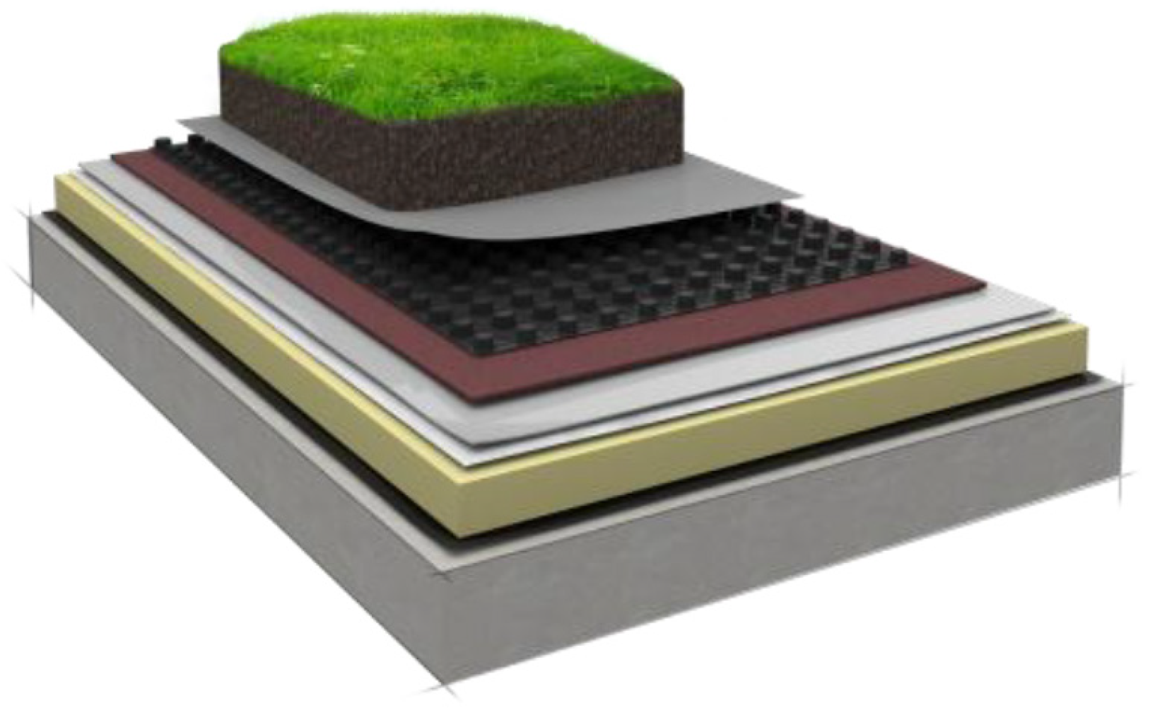
In the context of green roofs, a fundamental structural component is the drainage panel, whose primary function is twofold: to ensure the proper outflow of water percolating from the upper layers and to retain an appropriate service volume of water to sustain the vegetative system. An example of such a panel is illustrated in Figure 1, see the black element within the green roof. The figure shows that the panel consists of a modular grid; in addition to small collection basins, it incorporates structural elements designed to support the overlying layers of the rooftop garden.
Figure 1.
Example of a green roof, in black the drainage panel, image from Harpo Spa.
The hydraulic behavior of green roofs is often analyzed through conceptual models that apply the continuity equation across the various components of the system, assigning a specific hydraulic response to the drainage panel—such as free-surface flow [1] or, alternatively, a reservoir-based representation [2]. In the former case, with reference to Figure 1, describing the process solely through a uniform-flow equation may be inadequate, or at the very least, the determination of an equivalent roughness parameter may prove complex. A more refined conceptualization considers the domain as flow through an array of cylindrical structures. The resulting flow dynamics depend on several factors, including the flow regime—laminar or turbulent (see, for example, [3,4])—the geometric obstruction of the cylinders, and their spatial arrangement (see, for example, [5]). Each of these aspects can influence runoff by inducing head losses within the drainage system.
This study aims to examine the hydraulic behavior of a representative component of the drainage panel under conditions of brief and intense rainfall—scenarios that are critical for assessing the system’s drainage capacity. The analysis is carried out through detailed numerical modeling, assuming steady-state flow conditions for the sake of simplicity.
2. Materials and Methods
The numerical analyses were carried out by directly solving the Navier–Stokes equations, namely the continuity equation and the momentum conservation equation:
Here, the subscripts i and j denote the directions along the Cartesian axes. The variable x represents the spatial coordinate in the three directions according to the subscript i; u denotes the velocity; t is time; p the pressure; ρ the density; ν the kinematic viscosity; and B a body-force term. The latter is employed to represent the complex geometry of the draining panel through an Immersed Boundary Method (see [6,7]). This method enables the treatment of complex geometries using structured grids and allows the exact boundary conditions on the wall to be imposed via the body-force.
The system of equations is solved using a second-order accurate algorithm in both space and time, as in [8]. In particular, a semi-implicit time-integration scheme is employed to overcome diffusive stability constraints. Furthermore, the equations are solved directly, without resorting to turbulence models, a choice deemed appropriate given the resolution of the computational grid adopted.
The computational domain is restricted to the periodic directions of the panel. A representative element with horizontal dimensions Lx = Lz = 60 mm is considered, while the domain height Ly is determined under the assumption of uniform flow and is related to the prescribed inlet discharge. The computational cells have aspect ratios close to unity, with a characteristic size of approximately 0.3–0.36 mm. The total number of computational cells ranges between 1 and 1.7 million. Boundary conditions are specified as periodic in both the streamwise and spanwise directions, while a free-slip condition is applied at the top surface. The driving force of the flow is imposed through a pressure gradient chosen to balance gravitational and frictional forces.
Several cases were examined by varying the inlet discharge per unit surface—specifically 50, 100, and 150 mm/h—and by considering different roughness coefficients of 20, 50, and 80 m1/3/s. These coefficients were used to determine the flow depth through a uniform-flow equation applied to the effective flow cross-section. Across the various configurations, the Reynolds number (based on the Hydraulic diameter) ranges from 1059 to 3338, while in all cases the Froude number remains below unity.
3. Results
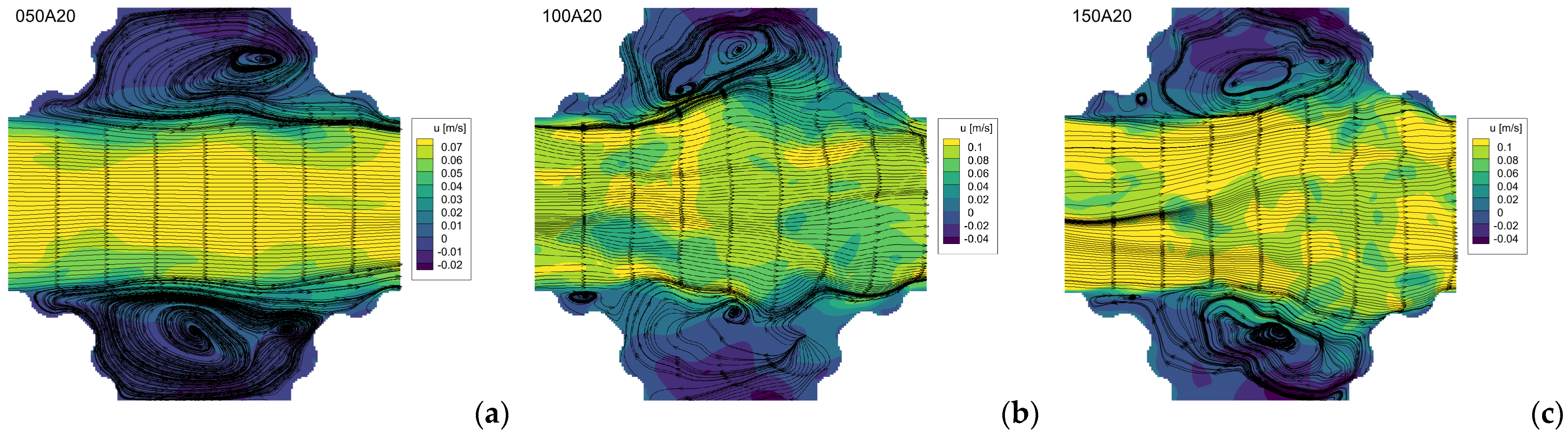
Figure 2 presents the instantaneous velocity field u along with the corresponding streamlines. For the case with an inlet discharge of 50 mm/h and a roughness coefficient Ks = 20 m1/3/s (050A20), large and relatively stable separation regions are observed, clearly delineating the interstitial channel between the support elements.
Figure 2.
Instantaneous u-velocity contours and streamlines on a mid-plane xz section for a surface roughness Ks = 20 m1/3/s and varying discharge: (a) Case 50 mm/h; (b) Case 100 mm/h; (c) Case 150 mm/h.
At higher flow rates, the cross-sectional area of the interstitial channel tends to expand in the x direction; the flow impinges on the downstream supports and promotes the development of recirculation zones. These separation regions exhibit increasingly time-dependent and variable characteristics.
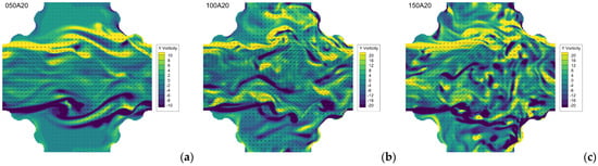
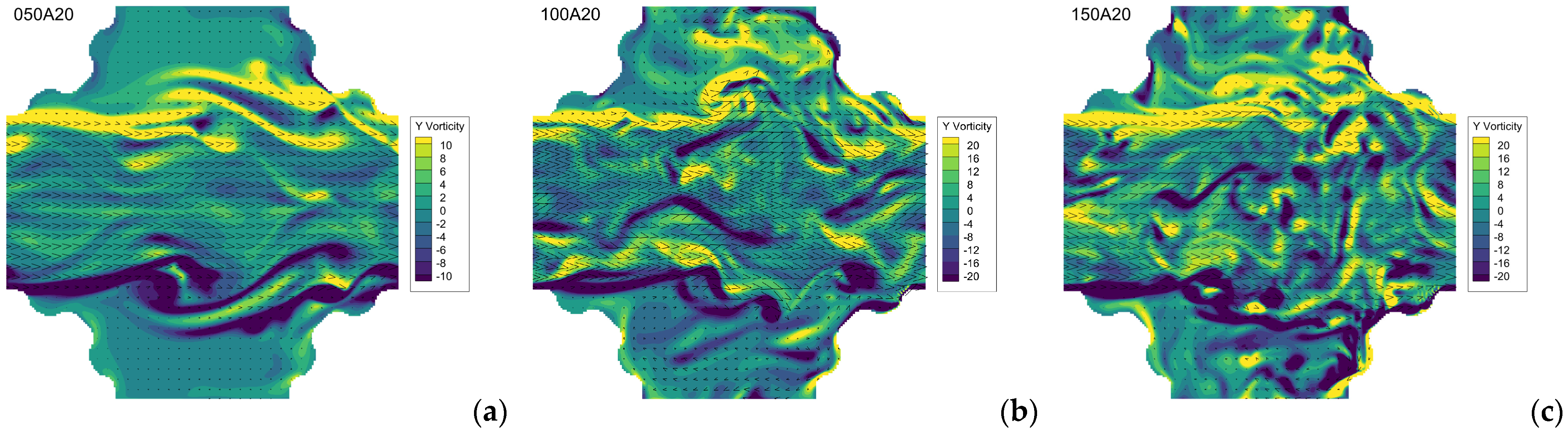
Figure 3 displays the instantaneous y-axis vorticity field on a mid-plane for varying inlet discharges. At low flow rates, vortex structures develop at the interface between the interstitial flow and the separation zones; these vortices are more elongated and occur less frequently owing to the reduced shear. Their extent appears comparable to the spacing between the support elements, which contributes to stronger confinement of the flow within the interstitial channel. As the discharge increases, the vortical structures become more frequent and intense, while their characteristic size decreases.
Figure 3.
Instantaneous y-axys vorticity contours and velocity vectors (black arrows, for clarity one vector out of every 25 is shown) on a mid-plane xz section for a surface roughness Ks = 20 m1/3/s and varying discharge: (a) Case 50 mm/h; (b) Case 100 mm/h; (c) Case 150 mm/h.
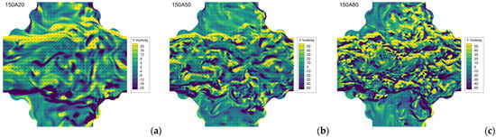
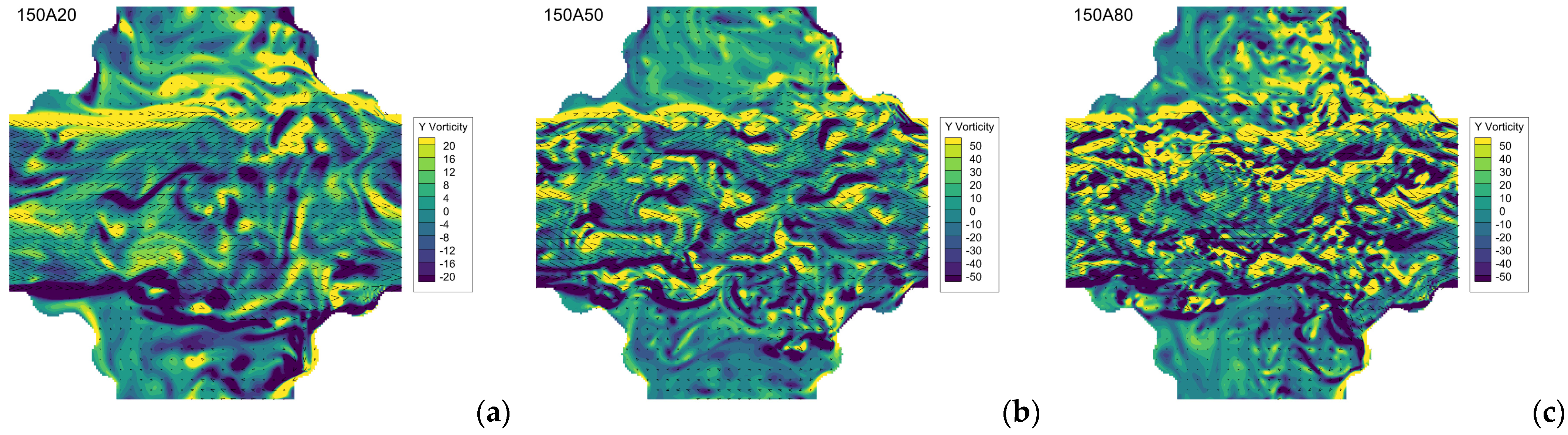
Figure 4 depicts the instantaneous y-axis vorticity field on a mid-plane for a discharge of 150 mm/h under varying surface roughness. As the roughness decreases, the vortical structures become smaller while increasing in frequency and intensity, exhibiting a behavior analogous to that observed when the flow rate is increased. A reduction in roughness also causes the separation zones to shrink and remain more closely confined to the upstream supports. This trend is consistent with the corresponding increase in the Reynolds number.
Figure 4.
Instantaneous y-axys vorticity contours and velocity vectors (black arrows, for clarity one vector out of every 25 is shown) on a mid-plane xz section for a discharge of 150 mm/h: (a) Case Ks = 20 m1/3/s; (b) Case Ks = 50 m1/3/s; (c) Case Ks = 80 m1/3/s.
4. Discussion and Conclusions
The results indicate that complex flow structures develop within the drainage panel, strongly influenced by the inlet discharge and surface roughness, that is, by the increase in Reynolds number. In particular, a pronounced interaction is observed between the interstitial channel and the area between the support elements, leading to the formation of separation zones that evolve significantly in both time and space. Although not quantified in the present study, it is evident that this behavior may have a substantial impact on localized losses, which could be critical to the hydraulic performance of the drainage panel. Further investigations will be conducted to assess the effect of the spacing between support elements, as well as the influence of flow orientations relative to the supports.
Author Contributions
Conceptualization, F.R. and S.A.; methodology, F.R.; software, A.A. and F.R.; validation, A.A. and F.R.; formal analysis, A.A. and F.R.; investigation, A.A. and F.R.; resources, A.A. and F.R.; data curation, A.A. and F.R.; writing—original draft preparation, A.A., F.R. and S.A.; writing—review and editing, A.A., F.R. and S.A.; visualization, A.A. and F.R.; supervision, F.R.; project administration, F.R. and S.A.; funding acquisition, S.A. All authors have read and agreed to the published version of the manuscript.
Funding
This research was funded by Regione Friuli-Venezia Giulia, Por Fesr 2021-2027—a1.3.1 Strumento di incentivazione a fondo perduto per la realizzazione di proof of concept (PoC).
Institutional Review Board Statement
Not applicable.
Informed Consent Statement
Not applicable.
Data Availability Statement
Data are available upon request, with the exception of the drainage panel geometry, which is subject to proprietary rights.
Conflicts of Interest
Author Sergio Andri was employed by the company Harpo S.p.a. via Caduti sul Lavoro 7, 34015 Muggia, Italy. The remaining authors declare that the research was conducted in the absence of any commercial or financial relationships that could be construed as a potential conflict of interest.
References
- Scott, J.; Garner, B.; Hidalgo, D.; Daoularis, D.; Warmerdam, O. Insights into green roof modeling using SWMM LID controls for detention-based designs. J. Water Manag. Model. 2022, 30, C484. [Google Scholar] [CrossRef] [Scilit]
- Carbone, M.; Garofalo, G.; Nigro, G.; Piro, P. A conceptual model for predicting hydraulic behaviour of a green roof. Procedia Eng. 2014, 70, 266–274. [Google Scholar] [CrossRef] [Scilit]
- Campo-Deano, L.; Galindo-Rosales, F.J.; Pinho, F.T.; Alves, M.A. Nanogel formation of polymer solutions flowing through porous media. Soft Matter 2012, 8, 6445. [Google Scholar] [CrossRef] [Scilit]
- da Silva, B.L.; Luciano, R.D.; Utzig, J.; Meier, F. Flow patterns and turbulence effects in large cylinder arrays. Int. J. Heat Fluid Flow 2018, 69, 136–149. [Google Scholar] [CrossRef] [Scilit]
- Forslund, T.O.M.; Larsson, I.A.; Hellstrom, J.G.I.; Lundstrom, T.S. The effects of periodicity assumptions in porous media modelling. Transp. Porous Media 2021, 137, 769–797. [Google Scholar] [CrossRef] [Scilit]
- Fadlun, E.A.; Verzicco, R.; Orlandi, P.; Mohd-Yusof, J. Combined immersed-boundary finite difference methods for three-dimensional complex flow simulations. J. Comput. Phys. 2000, 161, 35–60. [Google Scholar] [CrossRef] [Scilit]
- Roman, F.; Napoli, E.; Milici, B.; Armenio, V. An improved immersed boundary method for curvilinear grids. Comput. Fluids 2009, 38, 1510–1527. [Google Scholar] [CrossRef] [Scilit]
- Zang, Y.; Street, R.L.; Koseff, J. A non-staggered grid, fractional step method for time-dependent incompressible Navier-Stokes equations in curvilinear coordinates. J. Comput. Phys. 1994, 114, 18–33. [Google Scholar] [CrossRef] [Scilit]
Disclaimer/Publisher’s Note: The statements, opinions and data contained in all publications are solely those of the individual author(s) and contributor(s) and not of MDPI and/or the editor(s). MDPI and/or the editor(s) disclaim responsibility for any injury to people or property resulting from any ideas, methods, instructions or products referred to in the content. |
© 2026 by the authors. Licensee MDPI, Basel, Switzerland. This article is an open access article distributed under the terms and conditions of the Creative Commons Attribution (CC BY) license.