1. Introduction
During the development phase of a new radio-controlled aircraft characterized by a highly swept wing (Λ ~ 45°), strongly tapered planform (~0.3), and limited aspect ratio (
), a study on control surfaces was undertaken starting from traditional preliminary performance estimation methods, such as the DATCOM [
1] method, followed by a comparison with experimental measurements obtained in a wind tunnel. The need for this experimental investigation arose from the necessity to assess the influence of a different family of airfoils on the analytical predictions provided by DATCOM. In fact, the experimental spoileron investigations reported in the literature have been conducted exclusively using conventional airfoils, whereas the present test article is characterized by the adoption of reflex airfoils.
This comparative analysis gains further significance considering that the airfoils adopted are reflex airfoils (t/c ~ 10%) of innovative origin, derived from the practical field of flying-plank configurations [
2]. Consequently, these airfoils must also be regarded as highly experimental.
In particular, because the aft portion of the airfoil plays a decisive role in its self-stabilizing characteristics [
3], its interaction with the spoiler is of particular interest and warrants investigation, as this region is the most strongly influenced by spoileron deflection, which induces flow separation [
4].
The need to investigate not only the actual aerodynamic performance compared with the predicted one but also the interaction between these unconventional airfoils and spoileron-based control solutions motivated the execution of a dedicated wind-tunnel experimental campaign. Furthermore, an additional objective of this investigation was to improve the understanding of aircraft design tools for spoileron sizing, enabling the optimization of actuator requirements while maximizing aerodynamic performance.
The analyzed performances concern the capability of spoilers to generate rolling moment and the associated cross-coupling effects on yaw motion. Moreover, the study aimed to develop a performance map of the wing by varying the spoiler position both spanwise and chordwise, as well as modifying the geometric parameters of the spoileron itself, in order to evaluate how these variations could influence the resulting aerodynamic performance.
2. Testing Method
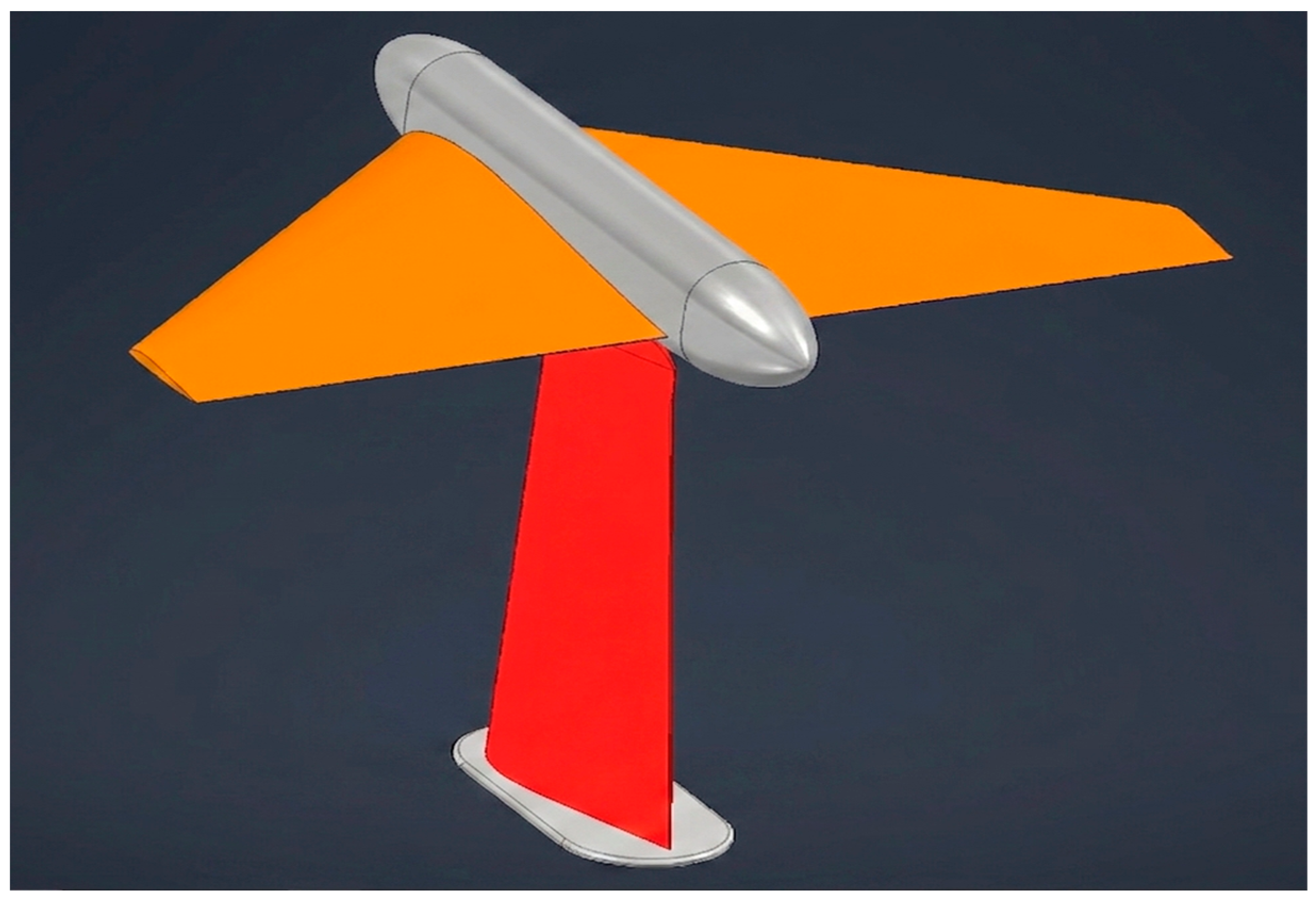
The model (represented in
Figure 1) was positioned at the center of a square test section with a side length equal to 1.8 times the wingspan. The dimensions of the test section were selected to provide sufficient clearance between the wing tips and the tunnel walls, thereby minimizing wall-interference effects as suggested by literature [
5]. The flow velocity was set at 30 m/s, corresponding to an equivalent Reynolds number of 930,000 [
6].
The data acquisition system was installed on the wind tunnel wall at the base of the support pylon, while the aerodynamic loads were measured using an external balance. The support pylon was enclosed within an aerodynamic fairing/shield to prevent its aerodynamic contribution from being included in the force and moment measurements.
The test model, machined from solid aluminum, consisted of two semi-wings mounted on a fuselage that is not geometrically representative of the actual aircraft configuration. This fuselage was specifically designed to minimize aerodynamic interference during the tests and to allow the installation of an electric motor for additional experiments related to propeller slipstream.
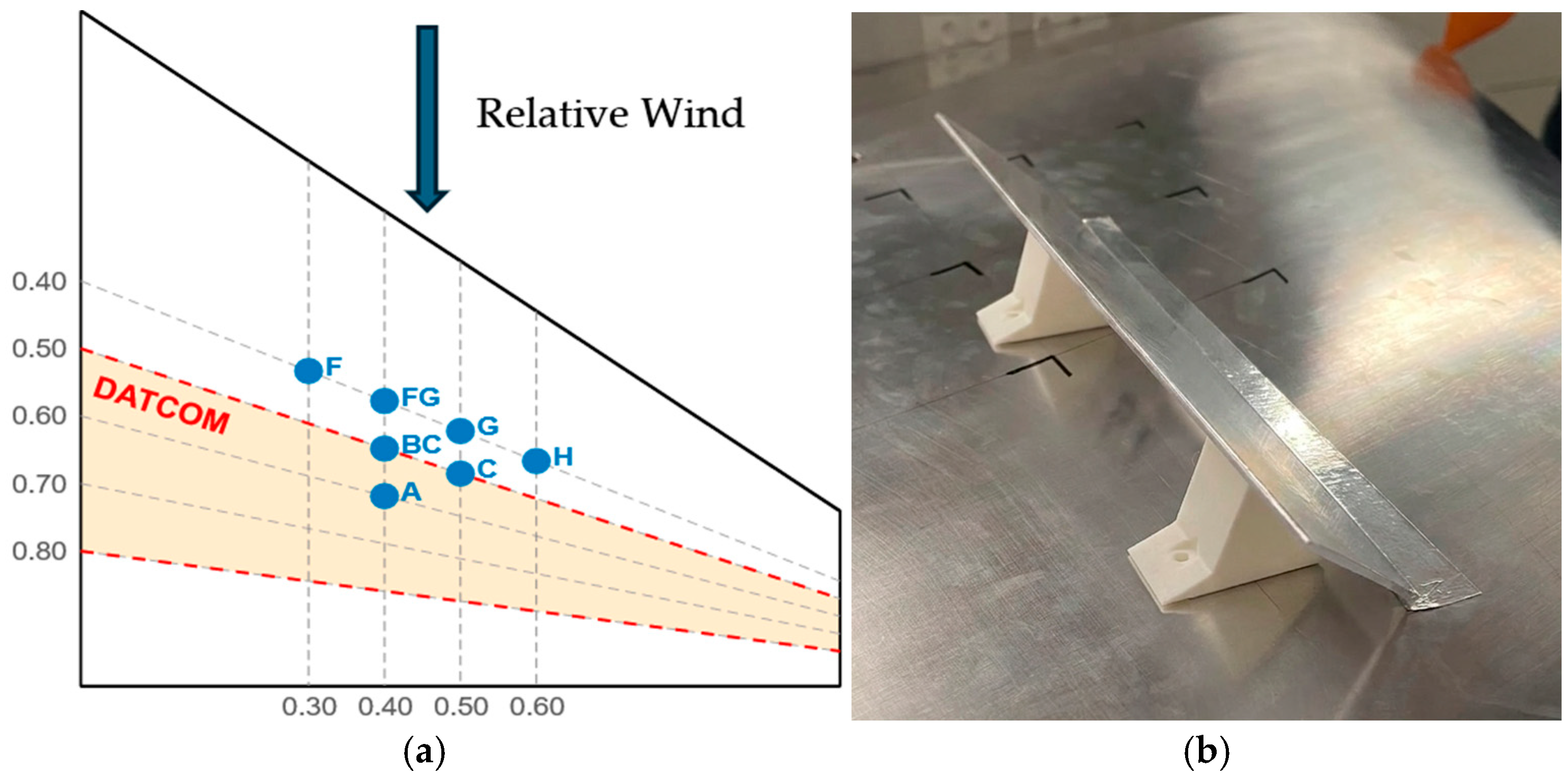
The experimental campaign was carried out by installing plain spoilerons manufactured from Plexiglas and secured using FDM 3D-printed supports (as shown in
Figure 2b) at various locations along the upper surface of the right wing (as shown in
Figure 2a).
The plain spoilerons were characterized by the following parameters: the ratio between the spoiler chord and the local wing chord , the ratio between the spoiler span and the wingspan , the geometric position along the wing chord or span, and the spoiler deflection angle .
A performance mapping of the plain-type spoiler was first conducted by maintaining constant spoiler-to-wing chord and span ratios, defined during the preliminary design phase of the RC model, while varying the spoiler starting position both in the spanwise (from 0.3 to 0.6 of the span) and chordwise directions (from 0.4 to 0.6), using the root-leading-edge corner of the spoileron as the reference point for its positioning along the wing.
It is important to note that some of the tested configurations lie outside the DATCOM reference validity range (0.5 to 0.8 wing-chord [
7]). For this reason, these test points proved particularly useful for extending the results obtained through interpolation from the regression models provided by the analytical methods, thereby assessing their applicability and potentially extending the validity range of the DATCOM approach.
Subsequently, at selected locations, the investigation was extended by varying either the spoiler-to-wing chord ratio (named Chord+) or the span ratio (named Span+). Upon completion of the performance mapping over the wing, a sensitivity analysis with respect to the spoiler deflection angle was also performed at the preliminary design position.
3. Results
The experimental campaign allowed a detailed evaluation of spoileron performance across a range of spanwise and chordwise positions, spoiler geometries, and angles of attack. The analysis revealed several consistent trends regarding roll and yaw control authority.
As shown in
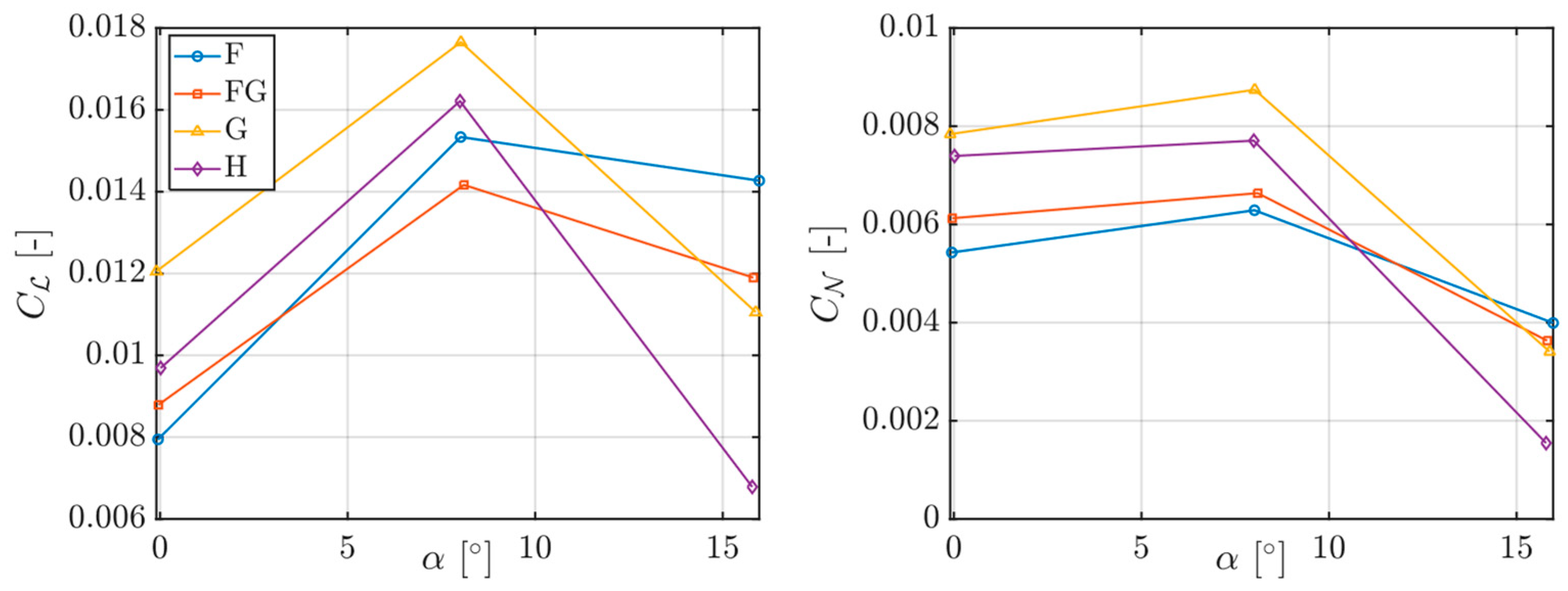
Figure 3, the position of the spoiler along the wingspan was found to strongly influence roll effectiveness. At low angles of attack, spoilers located closer to the wing tip generally produced larger rolling moments due to the greater moment arm relative to the aircraft’s longitudinal axis. Interestingly, the outermost spoilerons did not always correspond to the maximum effectiveness; rather, a mid-span location, approximately corresponding to point G in the experimental layout, provided the optimal compromise between roll authority and robustness against stall effects.
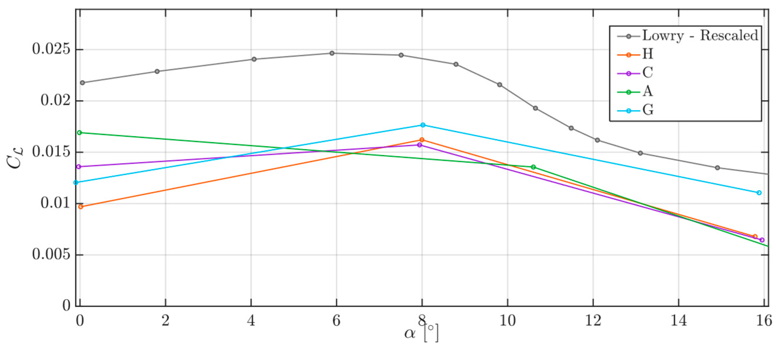
As the angle of attack increased, all spanwise configurations exhibited a peak in effectiveness at intermediate incidence, followed by a reduction in performance as the wing approached stall conditions, as stated also by Lowry in his work [
8] (
Figure 4).
The outer spoilerons experienced an earlier degradation, likely due to the onset of flow separation in the tip regions, whereas more inboard spoilerons maintained partial effectiveness over a wider range of incidence. These findings underscore the importance of mid-span spoiler placement for achieving stable control in highly swept, low-aspect-ratio wings.
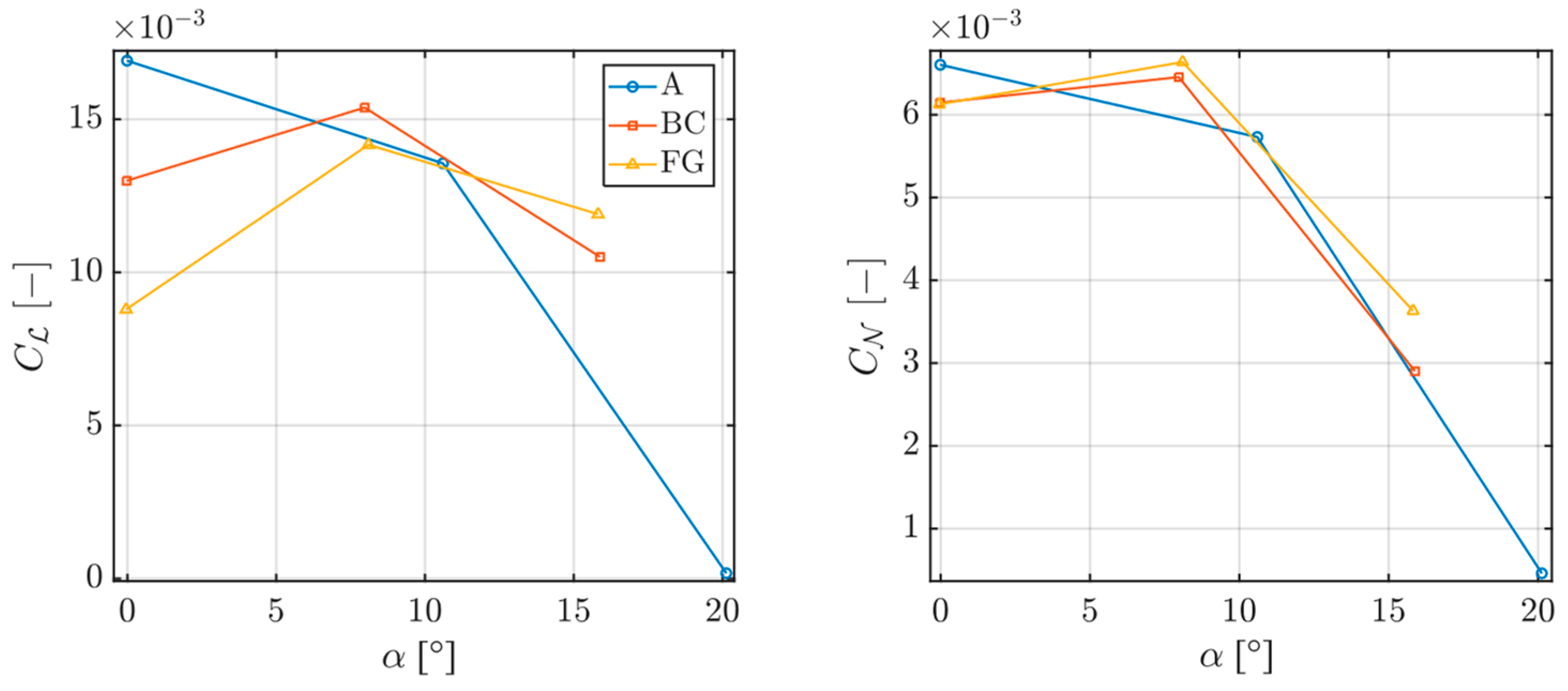
The effect of the spoiler chordwise position was therefore investigated for both roll and yaw control. This analysis was also motivated by the fact that, in DATCOM, the estimation of yawing effectiveness is treated in a more simplified manner than the corresponding roll analysis. Consequently, a more detailed assessment was performed to better characterize the resulting performance trends. Furthermore, it was hypothesized that flow development in the vicinity of stall conditions could significantly influence the effectiveness of spoilers located further aft along the chord, providing an additional motivation for investigating the impact of spoiler chordwise position.
At low angles of attack (
Figure 5), the best performance is obtained with the spoilers located further aft along the chord, closer to the trailing edge. At high angles of attack, however, the best performance is achieved with spoilers positioned further forward, closer to the leading edge. In the intermediate angle-of-attack range, a convergence of performance among configurations is expected. Unfortunately, due to the experimental campaign being conducted with different angles of attack for the A position, a complete comparison at intermediate incidence is unavailable due to a difference in the alpha of testing.
This behavior may be interpreted as a greater resistance, for forward-mounted spoilers, to the upstream propagation of the separation bubble originating from the trailing edge at the wingtip region during the stall.
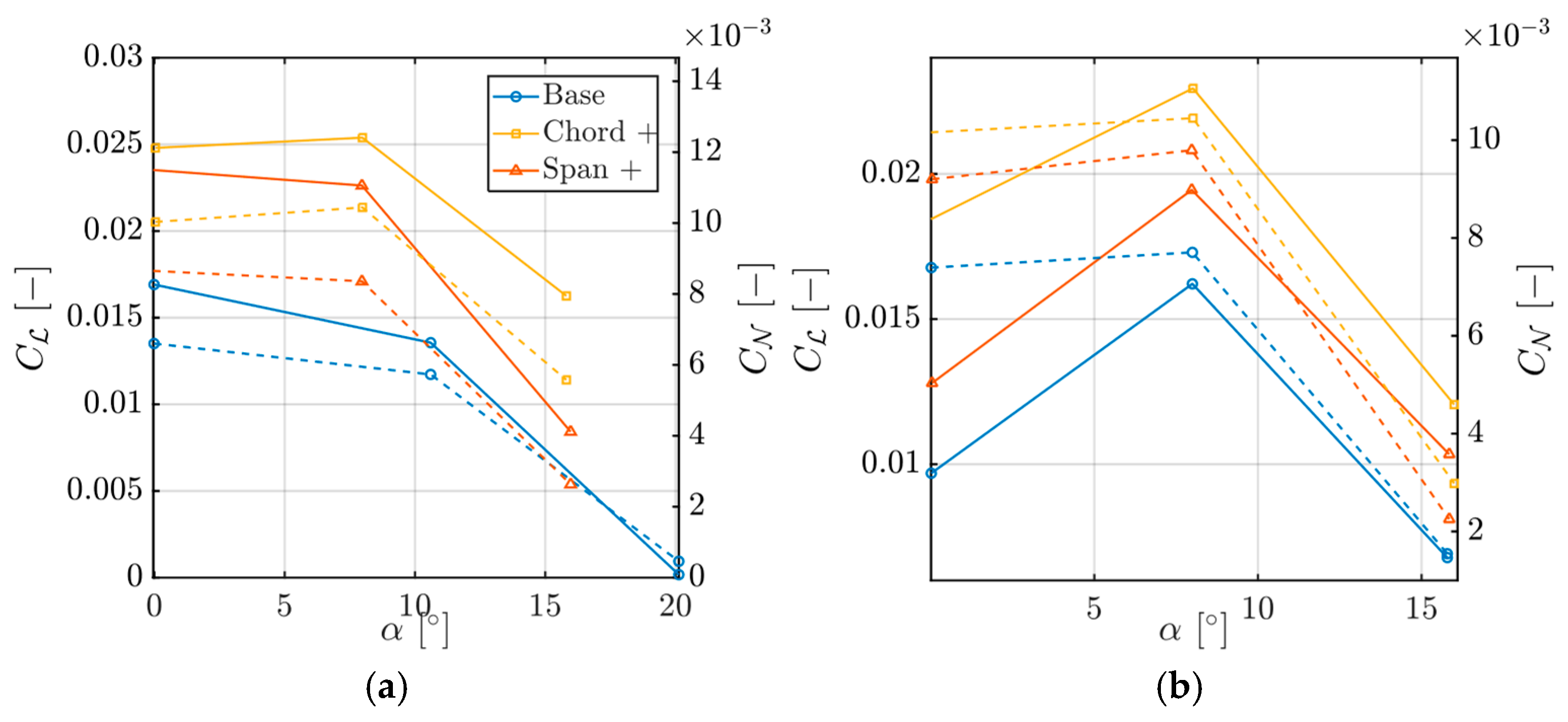
The geometric characteristics of the spoiler itself further modulated performance. Increasing either the chord or span resulted in enhanced roll authority, as expected. The influence of spoiler geometry was investigated at the A and H test locations through a dedicated sensitivity analysis. Two geometric modifications were considered: the spoiler chord ratio was increased from 0.15 to 0.30 (doubling the spoileron area), and the spoiler span was increased by approximately 34% while maintaining the original chord ratio.
As expected, both modifications led to an increase in roll-control effectiveness, as shown in
Figure 6. In particular, the increase in spoiler chord produced a larger enhancement in roll performance than that obtained through the corresponding span increase, having a larger total surface.
This observation suggests that the relationship between spoiler geometry and aerodynamic effectiveness cannot be assessed solely on the basis of the absolute increase in rolling moment. The comparison between the two geometric modification strategies therefore provides the basis for the discussion presented in the following section, where a normalized effectiveness metric is introduced to support design-oriented evaluations.
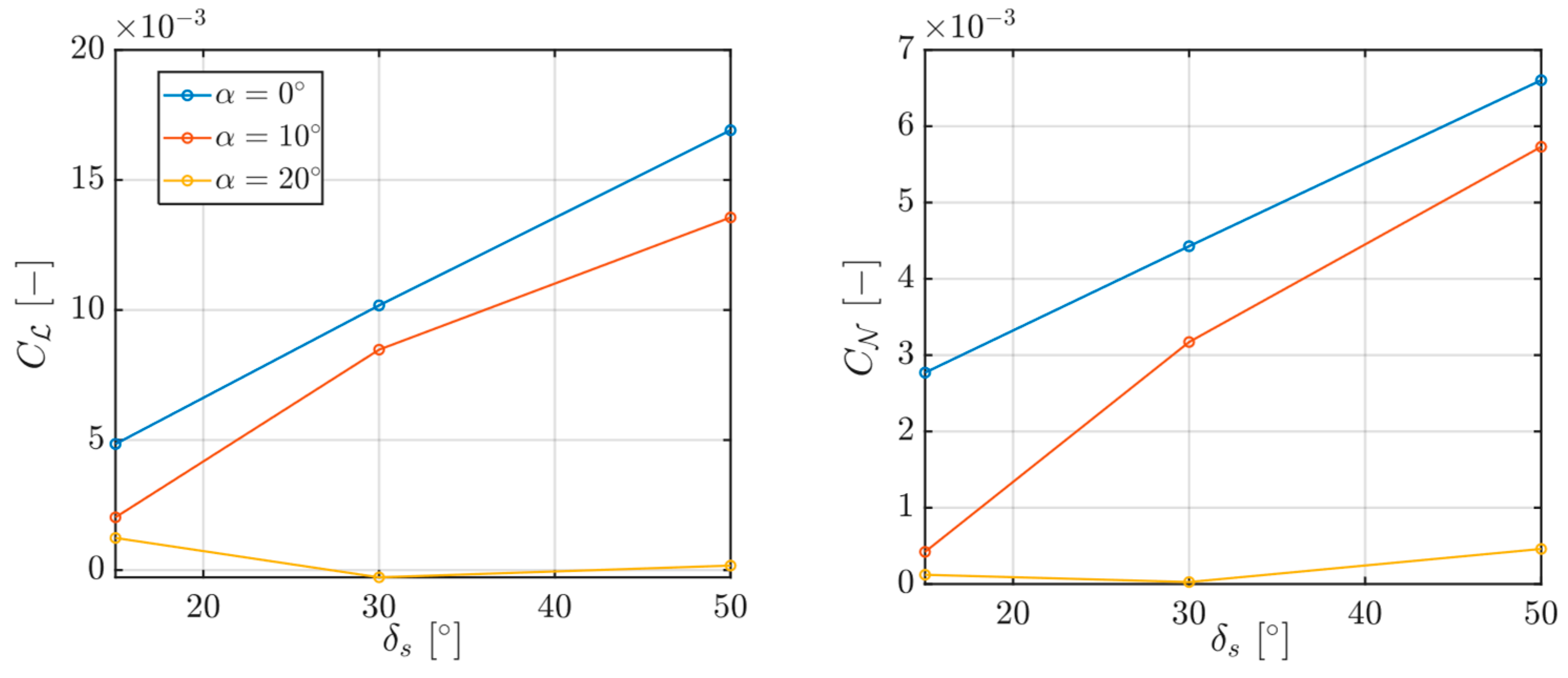
At positions A and H, a study was also conducted on roll performance as a function of surface deflection at angles of 15°, 30°, and 50° (
Figure 7). For angles of attack of 0° and 10°, the response is essentially linear. However, at 20°, beyond the aircraft’s stall angle, roll performance is almost entirely absent, as the spoilers have lost all authority.
When comparing these experimental results with the roll performance previously estimated using DATCOM, listed in
Table 1, discrepancies are observed, although they are not excessive. At this stage of the study, it is difficult to determine whether these differences are due to the presence of the reflex airfoil or the wing planform. Further investigations will be carried out to clarify this point.
4. Discussion
During data post-processing, two additional spoileron performance indices,
and
, were introduced (Equations (3) and (4)). These indices were conceived as design-oriented metrics to compare different spoileron locations based on the effectiveness generated by a unit spoiler area
acting through a unit moment arm
with respect to the center of gravity.
They therefore provide a useful tool for identifying the regions of the wing that offer the highest control efficiency, supporting both aerodynamic interpretation and preliminary spoileron design.
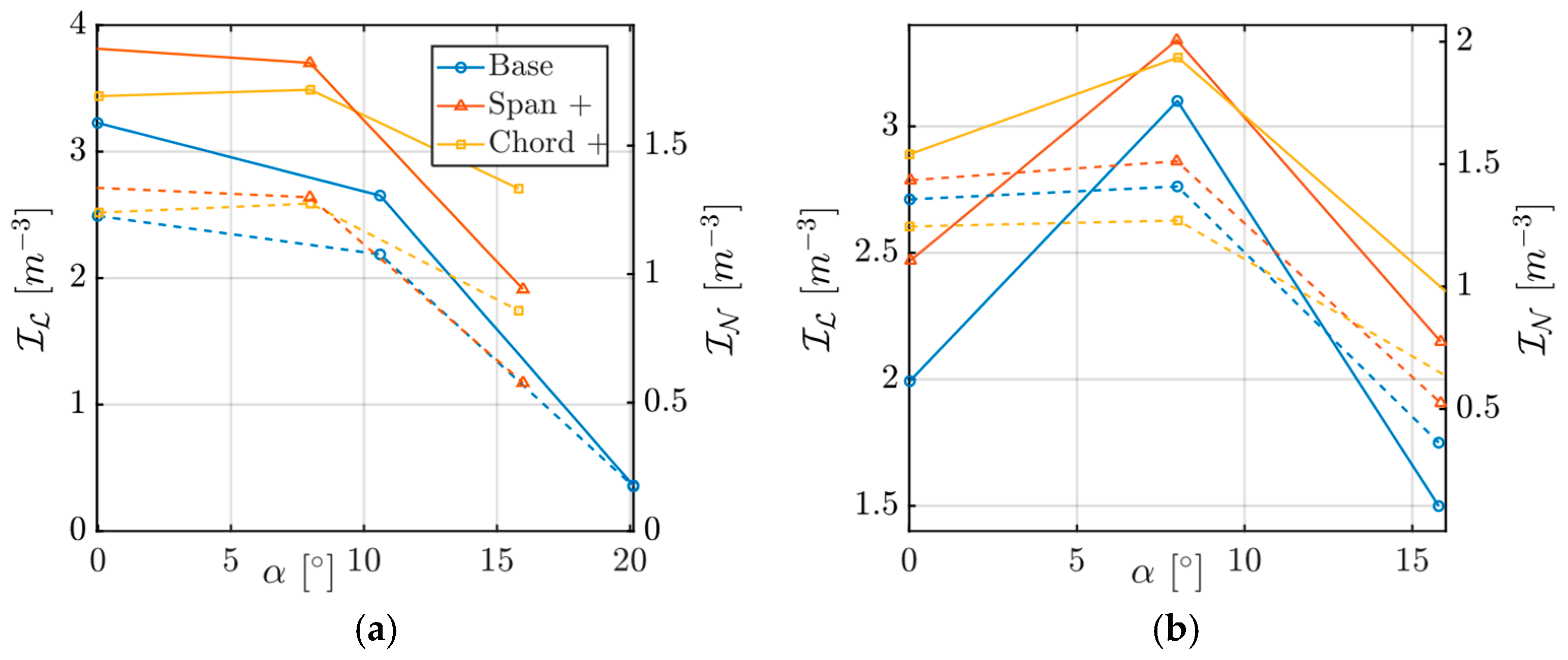
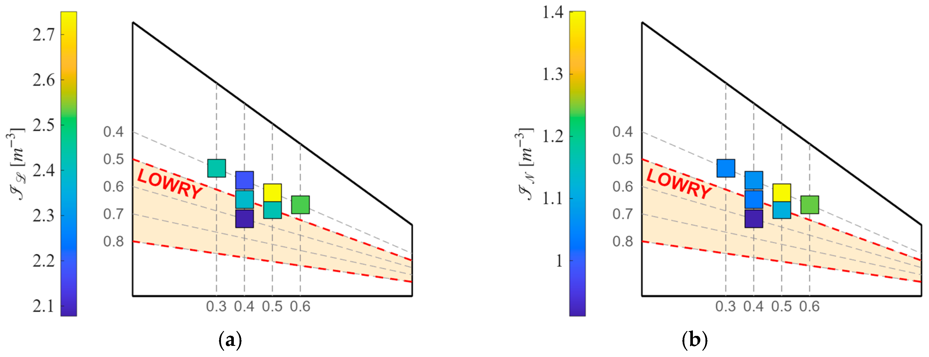
The results (
Figure 8) show that, for both positions A and H, at intermediate angles of attack (corresponding to the previously identified peak performance), this parameter exhibits overlap between tests with a doubled chord and tests with only a 34% increase in span.
This indicates that a smaller increase in spoileron span can achieve similar performance to doubling the chord but with reduced aerodynamic penalty (drag) as listed in
Table 2.
Therefore, designers can infer that, to achieve the same control effectiveness, it is preferable to operate on the spoileron span rather than the chord, thereby reducing actuator forces and overall system weight.
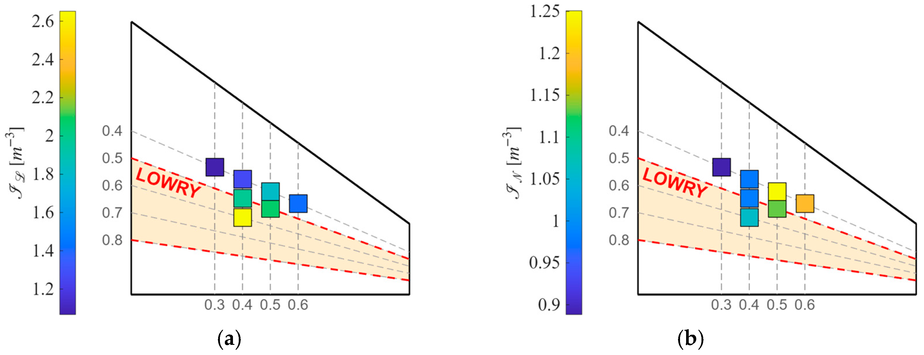
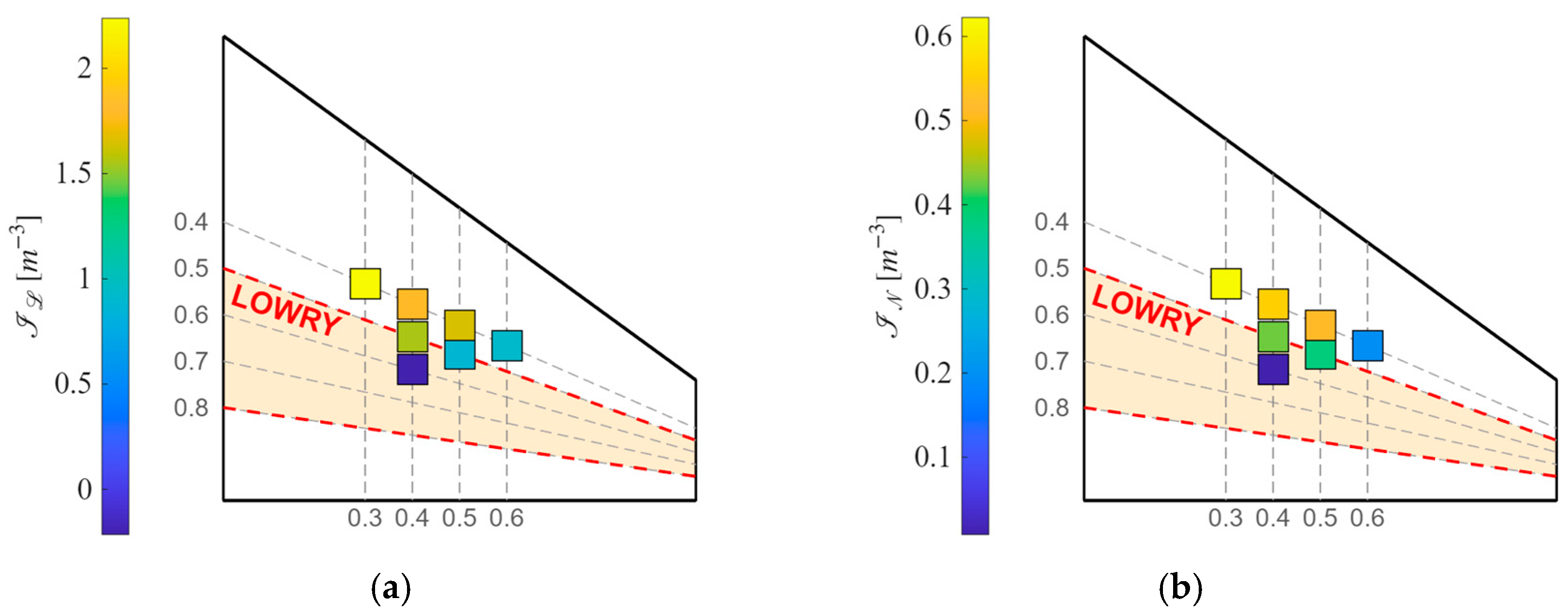
In the following images (
Figure 9,
Figure 10 and
Figure 11), it can be observed that the optimal spoiler placement remains within the central region of the test points. This represents the ideal compromise between performance at zero angle of attack and near-stall conditions, ensuring a delayed loss of control authority. Furthermore, it is evident that due to the stall phenomenon, the optimal point gradually shifts inward and toward a more forward position along the wing as the flow approaches separation conditions.
5. Conclusions
The present experimental campaign investigated the use of spoilerons as primary roll-control devices for a highly swept, low-aspect-ratio wing equipped with reflex airfoils. The wind-tunnel measurements provided an opportunity to evaluate both the applicability of conventional preliminary prediction methods and the influence of spoiler location and geometry on the resulting control authority.
The results showed that the overall behavior of the spoilerons remains consistent with trends commonly reported for conventional wing configurations. In particular, roll effectiveness was found to increase with angle of attack up to an intermediate-incidence condition, beyond which a degradation occurs as the wing approaches stall. While spoilerons positioned closer to the wing tip generate larger rolling moments at low incidence because of their greater moment arm, they also experience a more rapid loss of effectiveness as the angle of attack increases. This behavior is likely associated with the earlier onset of flow separation in the outer wing sections.
The experimental mapping of spoiler position highlighted the existence of a preferred installation region located approximately at the wing mid-span, as similarly shown in DATCOM and Tamburello’s report. The configuration identified as point G consistently provided the most favorable compromise between low-incidence effectiveness and robustness at higher angles of attack. This result is in agreement with trends reported in the available literature on spoiler-based roll-control systems.
The comparison between different spoiler geometries further showed that both chord and span increases lead to improved control authority. However, when the achieved performance is normalized through the proposed effectiveness index, span increases appear to provide a more efficient solution than chord increases. From a design perspective, this suggests that equivalent aerodynamic performance may be obtained with reduced actuation requirements and lower system weight by favoring spoiler span rather than chord.
Finally, although the motivation for the study originated from the use of reflex airfoils, no substantial deviations from the behavior expected for conventional airfoils were observed within the investigated test envelope. The present work should therefore be regarded as a first experimental assessment of spoileron performance on this class of unconventional configuration. Future investigations will focus on a finer discretization of spoiler geometry and position, as well as on a more detailed analysis of spoiler deflection effects.