


Abstract
This research proposes a unified, modular method for the preliminary design of unmanned airships, bridging the gap between static balance and dynamic performance. While traditional algorithms focus solely on global parameters like mass and volume, this approach integrates three original, in-house assembled tools for preliminary sizing, lofting and inertial modeling, and dynamic analysis. By synergically combining these modules, the system automatically solves weight and volume requirements while optimizing internal mass distribution for static balance. Furthermore, it extracts a linearized dynamic model from non-linear physics to evaluate and enhance flying qualities, like damping and eigenmode characteristic times, demonstrating the optimal procedure using an existing prototype.
Keywords:
airship; design; sizing; lighter than air; flying qualities; dynamics; lofting; modeling; simulation 1. Introduction
Airships, or lighter-than-air (LTA) vehicles, employ buoyant lift to achieve flight with exceptional endurance, payload efficiency, and low energy consumption. After a long decline caused by safety incidents and the rapid growth to dominance of heavier-than-air aviation, modern technological and environmental pressure is driving a renewed interest in LTA systems [1]. The demand for sustainable flight, combined with the feasibility of hybrid or fully electric propulsion, positions airships as credible platforms for low-emission, long-endurance, and low-infrastructure missions. Advances in composite materials, digital control [2,3,4,5,6,7], and computational aerodynamics have eliminated many of their historical limitations, while autonomous operation opens new roles in surveillance, communications, and logistics. Within this evolving aerospace landscape, airships now complement satellites and UAVs by offering multi-week endurance and high payload capacity at minimal operational cost [8,9].
Despite this renewed potential, modern airship design still lacks a unified and certification-oriented methodology. Unlike fixed-wing aircraft, where decades of standardization underpin mature design frameworks, the LTA field remains fragmented across preliminary sizing, mass and inertia estimation, aerodynamics, and dynamic flight analysis. Current tools rarely incorporate quantitative flying-quality metrics during design and often rely on post hoc verification, making early compliance evaluation impossible. Moreover, existing certification codes remain incomplete or outdated regarding airship stability and control requirements [10,11,12].
This work addresses these limitations through the development of A.L.D.O. (Airship Lofting & Design Optimizer), an integrated computational environment that links preliminary sizing, geometry generation, mass and inertia modeling, aerodynamic and dynamic simulation, and certification-oriented optimization within a single automated workflow. A.L.D.O. introduces a design-for-certification philosophy, where stability and handling-quality metrics are embedded directly into the optimization process. The framework thus provides a consistent and traceable pathway from mission requirements to certifiable design solutions, establishing a foundation for future developments in hybrid propulsion, control co-design, and multi-fidelity optimization of lighter-than-air vehicles.
2. Codes Overview
This work relies on three complementary computational environments that, once linked, form a single mission-driven workflow from preliminary sizing to dynamic evaluation.
2.1. Morning Star: Preliminary Sizing
Morning Star performs mission-driven sizing of LTA vehicles, delivering geometry, mass breakdown, and energy/power estimates, including solar-assisted options. It enforces buoyancy and mission constraints, providing a coherent baseline: hull parameters, subsystem weights and positioning, and first-order aerodynamic references [1,8,9].
2.2. AFL: Lofting and Inertial Properties
AFL converts the sized configuration into a 3D digital assembly with consistent inertial properties. It assigns precise volumes and masses to finite bodies and point items, and computes the center of gravity CCG center of buoyancy CCB, and inertia tensor JCB (from the center of buoyancy, but the capability of the code is not restricted to this choice). This enables an iterative alignment loop for static equilibrium (pendulum stability) by adjusting component placement (e.g., gondola and internal subsystems).
2.3. SILCROAD: Aerodynamics, Dynamics and Compliance with Certification Metrics
SILCROAD augments the digital model with aerodynamic coefficients, trim problem solution, linearization, and eigen-analysis. It evaluates flying qualities, such as damping ratios and time constants, and exposes certification-oriented figures of merit used later in the optimization routine [6,7,13,14].
2.4. Integrated Logic
Providing an automated Morning Star–AFL–SILCROAD link ensures traceable data continuity between geometry, inertia and dynamics. This enables a closed-loop, design-for-certifiability workflow in which mission objectives and regulatory metrics are consistently evaluated at every iteration.
3. A.L.D.O. Implementation
The A.L.D.O. (Airship Lofting & Design Optimizer) framework represents the integration of the three computational modules, Morning Star, AFL, and SILCROAD, into a single automated environment.
Within this unified structure, preliminary sizing, inertial modeling, and dynamic analysis are sequentially linked and complemented by an optimizer that refines geometry and internal mass distribution to enhance compliance with dynamic-flying-qualities and certification criteria.
3.1. Enhancements to Morning Star
The first development phase of the A.L.D.O. framework focused on upgrading the Morning Star code, the preliminary sizing environment of the design chain, based on the theory from [10]. The original tool, conceived for a fixed-geometry demonstrator, was extended to support a wider set of parametric hull definitions, thereby enabling the generation and analysis of alternative airship configurations within a unified computational scheme. A new shape function module was implemented to handle multiple analytic profiles, such as NPL, generalized NPL, elliptical, and Wang-type teardrop shapes, thus ensuring greater geometric flexibility and accuracy across different mission classes.
A parallel improvement concerned the allocation strategy of internal mass. A dedicated routine was developed to automatically align the center of gravity (CCG) with the center of buoyancy (CCB), enforcing the static equilibrium condition fundamental to lighter-than-air design. The method dynamically repositions movable subsystems (e.g., gondola, payload, batteries and internal systems) through an iterative fixed-point-based loop, achieving longitudinal alignment and a stabilizing vertical offset that ensures pendulum stability.
Additional refinements addressed debugging and modular integration: new functions were introduced for motor placement and hull sketching, while residual inconsistencies in legacy scripts were corrected. These modifications collectively transformed Morning Star from a standalone sizing code into a flexible, robust front-end capable of delivering fully parametrized, equilibrium-consistent configurations ready for downstream inertial modeling and dynamic certification analysis.
What Morning Star is not providing in particular is any accurate inertial modeling, i.e., the inertia tensor associated with a specific layout of all masses on-board. To this aim, a link to AFL had to be established.
3.2. Link to AFL
The second development phase focused on establishing a robust connection between the preliminary sizing environment (Morning Star) and the inertial assembly code AFL. A dedicated linking module was created to translate the high-level parametric outputs of the former, such as geometry, subsystem positions, and mass breakdown, into the detailed input structures required by the latter AFL code block.
A systematic user-settable classification of all subsystems was introduced to balance modeling accuracy and computational efficiency. Components contributing less than 5% of the total mass or lacking detailed data were treated as point masses, while geometrically or dynamically relevant elements (envelope, tail units, gondola) were represented as finite bodies. Intermediate bodies can be treated either through three- or five-point approximations, or as finite bodies, depending on the user-defined setup. This unified logic ensured consistent mass allocation and inertia transfer across both codes.
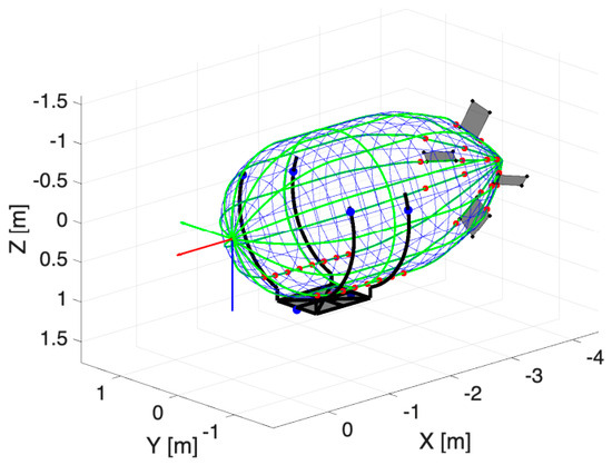
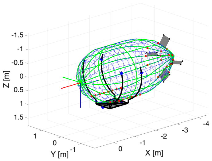
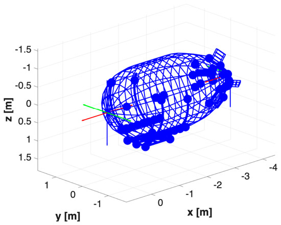
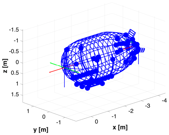
Results from the first linking phase, including updated finite-body masses and data-transfer consistency for geometry and positioning, are reported in Table 1 and Figure 1 and Figure 2, which are from the study airship developed and flown as a learning tool in the IPROP project [15] in preparation for the full-scale demonstrator planned for 2027. Notably, this airship was developed without employing ALDO, but according to a set of requirements (e.g., geometrical sizing limitations for indoor use, heavy envelope material, a gondola designed for the purpose of testing several configurations of the thrusters) yielding a low fineness ratio envelope. In this context, the results shown concerning the employment of the two modules compare the outcome of Morning Star alone to those obtained from AFL, the latter having worked on the outcome of Morning Star as a baseline. Notably, no optimization has been performed at this stage.
Table 1.
Mass variation between Morning Star and AFL for the IPROP study airship.
Figure 1.
Airship topological sketch, Morning Star. Red dots represent patches for component attachment. In black are the gondola tray and motor support structures. Red-green-blue triad on the envelope tip.
Figure 2.
Airship sketch, AFL. Dots represent point masses. Red-green-blue triads on the envelope tips (forward and backward).
3.3. Link to SILCROAD
The final step in the A.L.D.O. workflow established the automated transfer of the digital airship model from the inertial environment AFL to the dynamic simulation platform SILCROAD. A dedicated linking routine was developed to convert the structural and inertial outputs of AFL into a complete aerodynamic–dynamic representation. This procedure introduced the final set of physical parameters, namely, aerodynamic coefficients, thrust laws, and interference factors, automatically derived from geometry through regression functions based on established references [15,16,17,18].
The module enables SILCROAD to operate as a numerical wind-tunnel and certification tool, performing trim, linearization, and eigenvalue analyses under fully automated conditions. The implemented pipeline ensures that each simulation reflects the upstream mass distribution, buoyancy ratio, and propulsive configuration defined within AFL, while preserving full tunability through the master input script.
This stage also introduced the theoretical framework for the final optimization task, centered on dynamic-stability metrics derived from military flight-quality standards [19,20] transposed to the lighter-than-air domain, due to the lack of specific references for the airship environment. In particular, the longitudinal pendulum and side-slip subsidence modes were selected as key performance indicators, with compliance expressed in terms of damping ratio and doubling-time thresholds. The resulting automated pipeline thus delivers a fully consistent design-to-simulation process, bridging preliminary geometry, inertial modeling, and dynamic certification within a single parametric environment.
4. Optimization Routines
The final stage of the A.L.D.O. framework introduced a fully automated optimization and parametric analysis environment, completing the digital design loop. The implemented optimizer operates on a variable vector u = {dz, dx, dy}, which governs the internal displacement of the gondola subsystems. These displacements indirectly modify the vertical separation between the centers of buoyancy and gravity (h = zCG − zCB) and the yaw inertia Izz, the two parameters with the greatest impact on the longitudinal and lateral-directional dynamic modes.
The target of the optimization is the minimization of a cost function J(u) = wpenrpen2+ wssrss2 + wregrreg2, defined in terms of certification-oriented dynamic metrics. Namely, the phugoid (associated with longitudinal pendulum for an airship) damping ratio ζph and the spiral-mode (associated with side-slip subsidence for an airship) doubling time T2,sp, derived from MIL-F-8785C and MIL-STD-1797 adapted criteria, are employed as targets in the quadratic norms represented by rpen and rss, respectively, for pendulum and side-slip subsidence. A numerically stabilizing term has been included through the overall volume of the airship, which is compared to the first-guess one in the additional component rreg [20,21,22]. Weights wpen = wss and wreg are employed to modulate the effect of the stabilizing term.
The optimization process employs a gradient-based optimization routine with optional multi-start parallelization to avoid local minima. At each iteration, the solver re-executes the sizing and assembly procedures to ensure that mass properties, buoyancy equilibrium, and dynamic characteristics remain physically consistent.
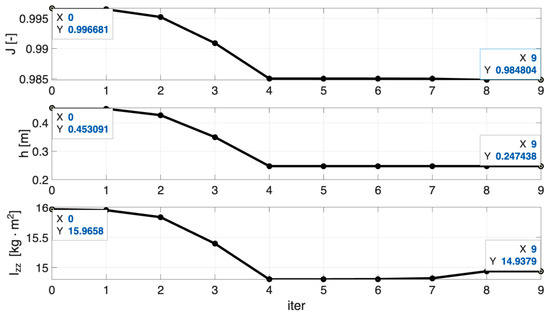
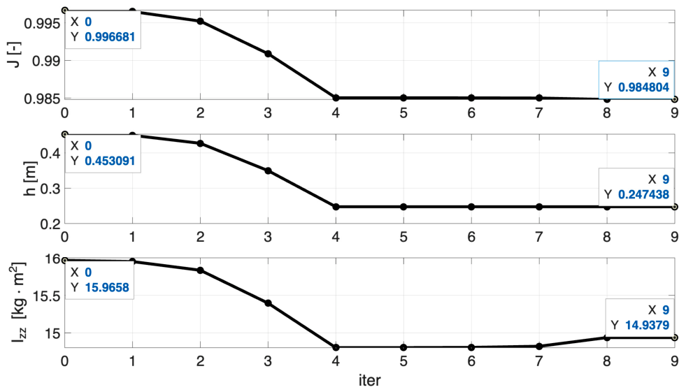
The evolution of the optimization process is shown in Figure 3 for the IPROP study airship case, highlighting the variation in the dependent parameters Izz and h during the minimization of J. The resulting optimized baseline configuration exhibits a moderate decrease in h and a slight increase in Izz, leading to a dynamically improved equilibrium, as confirmed by the minimum achieved value of the cost function J.
Figure 3.
Best-start properties trend when running ALDO employing, IPROP study airship case.
The second stage expanded the analysis into a two-dimensional parametric space defined by flight velocity v ∈ [1, 5] m/s and buoyancy ratio BR ∈ [0.99, 1]. For each (v, BR) pair, the optimizer was executed to convergence, producing local minima of J and enabling the identification of the optimum among optima.
Results show that the most stable configurations occur at low velocity and slightly under-buoyant conditions (v = 1 m/s, BR = 0.99), where both phugoid (pendulum) and spiral (side-slip subsidence) stability approach certification limits. As v increases, the airship exhibits reduced damping and shorter spiral time constants, reflecting the typical degradation of stability at higher dynamic pressures.
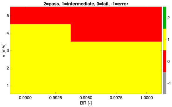
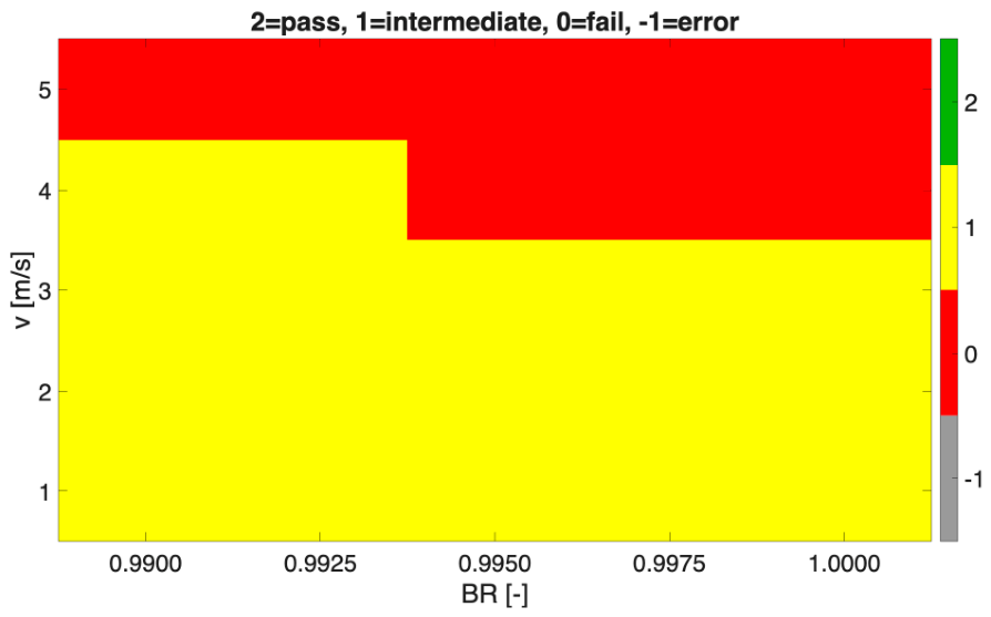
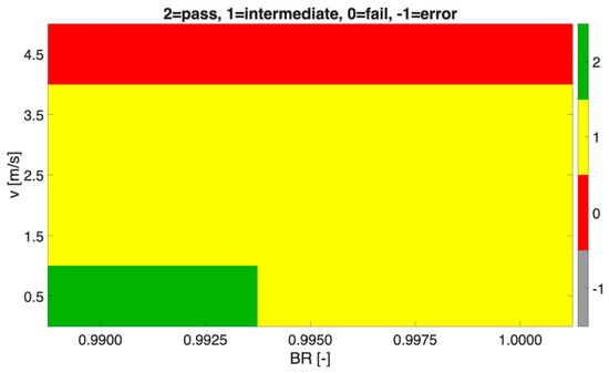
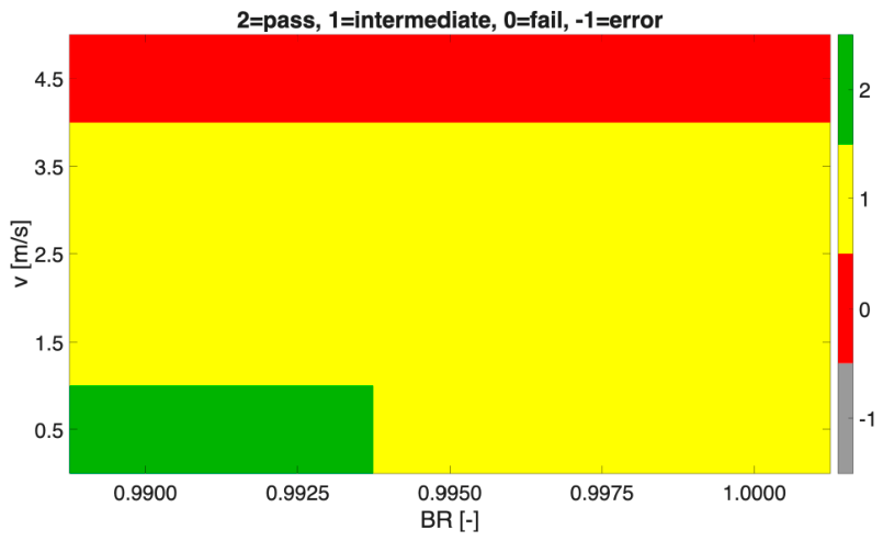
The certification pass/fail map shown in Figure 4 demonstrates that the IPROP study airship configuration never succeeds in simultaneously meeting both certification constraints, mainly due to the spiral (side-slip) mode, which consistently fails to reach the 20 s target for its doubling time. This behavior is primarily attributed to the low fineness-ratio of this study airship, and to the complete absence of movable control surfaces on the tail, whose limited area further reduces its potential influence on stability and control. Additional heatmaps of ζph, T2,sp, and J* (optimal J value) confirm these trends, while 3D surfaces of hopt and Izzopt demonstrate monotonic growth with velocity, consistent with the compensatory mass redistribution of the optimizer [22].
Figure 4.
Certification pass/fail map, IPROP study airship. Green: pass. Yellow: marginal. Red: fail.
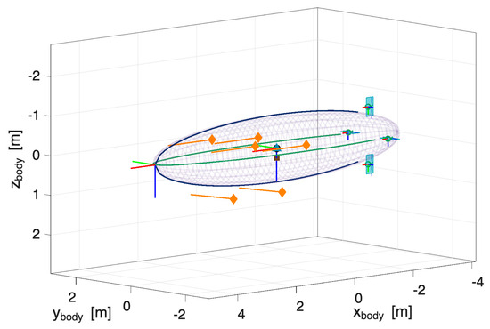
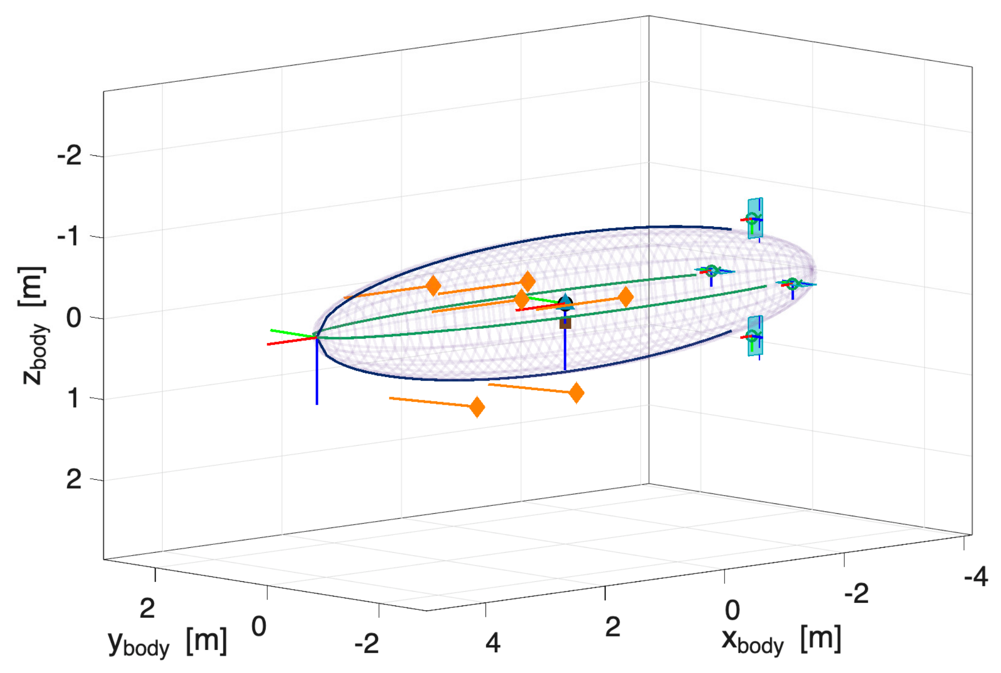
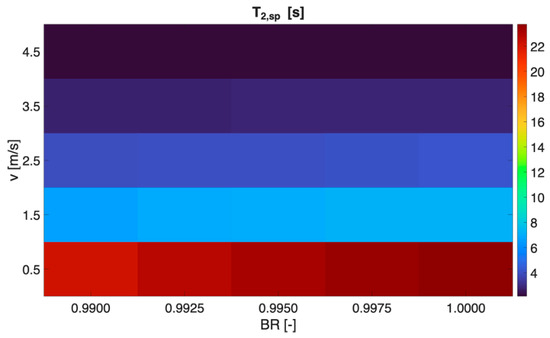
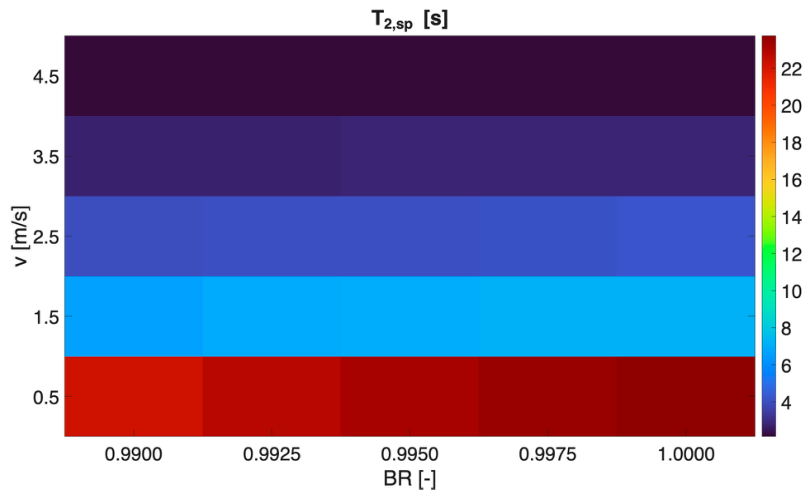
The framework was finally validated on an alternative, more streamlined airship configuration (Figure 5), not made in practice but envisioned specifically to revert to a more conventional design compared to the IPROP study airship. This can achieve full compliance with the stability criteria at low velocities. This is demonstrated by the relatively high value of the doubling time T2,sp of the spiral (associated with side-slip subsidence) mode for different values of design BR and airspeed v, and by the overall pass/fail map, respectively, in Figure 6 and Figure 7. The latter is significantly more favorable than the one in Figure 4.
Figure 5.
Alternative airship configuration sketch, SILCROAD. Showing the envelope and tail sizing. Blue dot: center of buoyancy. Dark square: center of gravity. Orange diamonds: thrusters (and thrust vector direction). Red-green-blue triads on the envelope tip, center of buoyancy and empennages.
Figure 6.
Alternative configuration T2,sp values across the operational domain.
Figure 7.
Certification pass/fail map, alternative configuration. Green: pass. Yellow: marginal. Red: fail.
This confirmed the generality and robustness of the proposed methodology, capable of reproducing realistic aerodynamic–inertial couplings and autonomously converging toward dynamically certifiable airship configurations.
5. Conclusions
The A.L.D.O. (Airship Lofting & Design Optimizer) framework successfully unified preliminary sizing, inertial modeling, aerodynamic simulation, and certification-oriented optimization into a single automated process. Starting from mission inputs, the toolchain consistently generates equilibrium-validated configurations, performs dynamic stability analyses, and refines mass distribution to improve compliance with flying-quality standards. The framework demonstrated the feasibility of embedding regulatory metrics, such as damping ratios and modal time constants, directly within the design loop, achieving a measurable enhancement of stability and controllability without compromising mission efficiency.
Beyond the numerical results, A.L.D.O. establishes a repeatable, physically grounded methodology that bridges classical airship design and modern digital engineering. It represents a foundational step toward a future Certification by Analysis (CbA) [23] workflow for lighter-than-air vehicles and provides a scalable platform for upcoming research in hybrid propulsion, control co-design, and multi-fidelity optimization. In essence, this work shows how automated integration, once a conceptual goal, can now define the future of airship design practice.
Author Contributions
Conceptualization, C.E.D.R. and L.A.; methodology, C.E.D.R. and L.A.; software, L.A.; validation, L.A.; formal analysis, C.E.D.R. and L.A.; investigation, C.E.D.R. and L.A.; resources, C.E.D.R.; data curation, L.A.; writing—original draft preparation, L.A.; writing—review and editing, C.E.D.R. and L.A.; visualization, L.A.; supervision, C.E.D.R.; project administration, C.E.D.R.; funding acquisition, C.E.D.R. All authors have read and agreed to the published version of the manuscript.
Funding
This project has received funding from the European Union’s Horizon Europe Research and Innovation Programme, under grant agreement No. 101098900. Views and opinions expressed are, however, only those of the authors and do not necessarily reflect those of the European Union or European Innovation Council and SMEs Executive Agency (EISMEA). Neither the European Union nor the granting authority can be held responsible for them.
Institutional Review Board Statement
Not applicable.
Informed Consent Statement
Not applicable.
Data Availability Statement
The dataset corresponding to the graphical results presented in this research is publicly available on Zenodo with 10.5281/zenodo.19366310.
Conflicts of Interest
The authors declare that there are no conflicts of interest.
References
- Riboldi, C.E.D.; Fanchini, L. Assessing the technical economic feasibility of low altitude unmanned airships: Methodology and comparative case studies. Aerospace 2025, 12, 244. [Google Scholar] [CrossRef] [Scilit]
- Paiva, E.; Benjovengo, F.; Bueno, S.; Ferreira, P. Sliding mode control approaches for an autonomous unmanned airship. In Proceedings of the 18th AIAA Lighter-Than-Air Systems Technology Conference, Seattle, WA, USA, 4–7 May 2009. [Google Scholar]
- Zheng, Z.; Huo, W.; Wub, Z. Trajectory tracking control for underactuated stratospheric airship. Adv. Space Res. 2012, 50, 906–917. [Google Scholar] [CrossRef] [Scilit]
- Liesk, T.; Nahon, M.; Boulet, B. Design and experimental validation of a nonlinear low-level controller for an unmanned fin-less airship. IEEE Trans. Control Syst. Technol. 2013, 21, 149–161. [Google Scholar] [CrossRef] [Scilit]
- Chen, L.; Zhang, H.; Duan, D.P. Control system design of a multivectored thrust stratospheric airship. Proc. Inst. Mech. Eng. Part G J. Aerosp. Eng. 2014, 228, 2045–2054. [Google Scholar] [CrossRef] [Scilit]
- Riboldi, C.E.D.; Rolando, A. Thrust-based stabilization and guidance for airships without thrust-vectoring. Aerospace 2023, 10, 344. [Google Scholar] [CrossRef] [Scilit]
- Riboldi, C.E.D.; Rolando, A. Autonomous flight in near hover and hover for thrust controlled unmanned airships. Drones 2023, 7, 545. [Google Scholar] [CrossRef] [Scilit]
- Riboldi, C.E.D.; Rolando, A.; Regazzoni, G. On the feasibility of a launcher-deployable high-altitude airship: Effects of design constraints in an optimal sizing framework. Aerospace 2022, 9, 210. [Google Scholar] [CrossRef] [Scilit]
- Riboldi, C.E.D.; Belan, M.; Cacciola, S.; Terenzi, R.; Trovato, S.; Usuelli, D.; Familiari, G. Preliminary Sizing of High-Altitude Airships Featuring Atmospheric Ionic Thrusters: An Initial Feasibility Assessment. Aerospace 2024, 11, 590. [Google Scholar] [CrossRef] [Scilit]
- Carichner, G.E.; Nicolai, L.M. Fundamentals of Aircraft and Airship Design; American Institute of Aeronautics and Astronautics, Inc.: Reston, VA, USA, 2013. [Google Scholar]
- Kornienko, A. System Identification Approach for Determining Flight Dynamical Characteristics of an Airship from Flight Data. Ph.D. Thesis, University of Stuttgart, Stuttgart, Germany, 2006. [Google Scholar]
- Kämpf, B.G. Flugmechanik und Flugregelung von Luftschiffen. Ph.D. Thesis, University of Stuttgart, Stuttgart, Germany, 2004. [Google Scholar]
- Riboldi, E.D.; Rolando, A. Layout Analysis and Optimization of Airships with Thrust-Based Stability Augmentation. Aerospace 2022, 9, 393. [Google Scholar] [CrossRef] [Scilit]
- Riboldi, E.D.; Tomasoni, M. Formation Flight of Fixed-Wing UAVs: Dynamic Modeling, Guidance Design, and Testing in Realistic Scenarios. Aerospace 2025, 12, 260. [Google Scholar] [CrossRef] [Scilit]
- H2020—EIC Pathfinder Open, IPROP—Ionic Propulsion in the Atmosphere. Grant N. 101098900, 2023–2027. Available online: www.iprop-project.eu (accessed on 27 May 2026).
- Jones, S.P.; DeLaurier, J.D. Aerodynamic estimation techniques for aerostats and airships. J. Aircr. 1982, 20, 120–126. [Google Scholar]
- Munk, M.M. The Aerodynamic Forces on Airship Hulls; NACA Technical Report No. 184; National Advisory Committee for Aeronautics: Washington, DC, USA, 1924. [Google Scholar]
- Hoerner, S.F. Fluid-Dynamic Drag, Hoerner Fluid Dynamics; Hoerner Fluid Dynamics: Bakersfield, CA, USA, 1965. [Google Scholar]
- Wardlaw, B.J. High Angle-of-Attack Missile Aerodynamics; AGARD Lecture Series 98; Advisory Group for Aerospace Research and Development: Neuilly-sur-Seine, France, 1979; pp. 5(1)–5(53). [Google Scholar]
- USAF. MIL-F-8785C Military Specification: Flying Qualities of Piloted Airplanes; USAF, Wright Patterson AFB: Dayton, OH, USA, 1980. [Google Scholar]
- USAF. MIL-STD-1797 Flying Qualities of Piloted Aircraft; Wright Patterson AFB: Dayton, OH, USA, 1997. [Google Scholar]
- Riboldi, C.E.D.; Alessi, L.; Terenzi, R. Airship Sizing for Flying Qualities: An Automated Methodology and Applications. J. Aircr. 2026. Epub ahead of printing. [Google Scholar] [CrossRef] [Scilit]
- Mauery, T.; Alonso, J.; Cary, A.; Lee, V.; Malecki, R.; Mavriplis, D.; Medic, G.; Schaefer, J.; Slotnick, J. A Guide for Aircraft Certification by Analysis; NASA: Washington, DC, USA; The Boeing Company: Arlington, VA, USA; Stanford University: Stanford, CA, USA; Pratt & Whitney: East Hartford, CT, USA; University of Wyoming: Laramie, WY, USA, 2021.

Disclaimer/Publisher’s Note: The statements, opinions and data contained in all publications are solely those of the individual author(s) and contributor(s) and not of MDPI and/or the editor(s). MDPI and/or the editor(s) disclaim responsibility for any injury to people or property resulting from any ideas, methods, instructions or products referred to in the content. |
© 2026 by the authors. Licensee MDPI, Basel, Switzerland. This article is an open access article distributed under the terms and conditions of the Creative Commons Attribution (CC BY) license.