


Abstract
Distributed Electric Propulsion (DEP) offers new opportunities for improving aircraft efficiency and control authority, but the strong interaction between propeller slipstreams and lifting surfaces makes aerodynamic behavior difficult to predict with conventional models. In particular, the effect of propeller blowing on trimmed aerodynamic characteristics must be assessed directly from flight data. An autonomous flight-test campaign was therefore conducted with the SwitchMaster, a six-propeller DEP demonstrator, using a TECS-based control architecture to acquire repeatable trim conditions over different advance ratio ranges. Identified longitudinal derivatives were used to reconstruct lift, drag and trimmed polar curves. The results show increased lift, reduced drag and improved aerodynamic efficiency in high-blowing, high-lift conditions, while highlighting nonlinear and non-monotonic aero-propulsive trends at intermediate propeller advance ratios.
1. Introduction
Distributed Electric Propulsion (DEP) represents a promising solution among unconventional aircraft design concepts, because the interaction between the propellers and the wing is exploited in an attempt to increase the overall aerodynamic performance, mainly in terms of lift, efficiency and control authority augmentation [1,2,3,4,5], while offering increased propulsion system redundancy.
However, the aerodynamic coupling between propeller slipstreams and the airframe introduces strong nonlinearities that challenge conventional modeling techniques [6]. To address this challenge, a dedicated research effort has been conducted at the Politecnico di Milano using the SwitchMaster demonstrator, an electrically powered, radio-controlled aircraft featuring six propellers distributed along the leading edge of the wing.
Earlier studies [7,8,9,10] focused on the design, preliminary flight testing, and development of an autonomous flight control framework based on a Total Energy Control System (TECS). Building on that foundation, a global aero-propulsive model was identified from flight data [11], starting from the local identification of single maneuvers. The identification campaign was conducted using an autonomous flight-test procedure designed to systematically excite the aircraft’s dynamic modes under different blowing conditions. The identified model captures the impact of distributed propellers on stability and control derivatives, providing a formulation for subsequent simulation and control studies.
Another important aim of the latest campaign was the derivation of static aerodynamic characteristics from the locally identified stability and control derivatives, which represent the novel topic addressed in this contribution.
2. Methodology
In this section, the design and execution of the autonomous flight-testing campaign are briefly reported, starting from the main autopilot features implemented to the flight plan and maneuvers designed. Then, the model identification process employed to capture the aircraft dynamics and aero-propulsive interaction is described, with a particular focus on the local estimation of stability and control derivatives and reconstruction of trimmed aerodynamic characteristics in the function of propeller blowing.
2.1. Autonomous Flight and Model Identification Procedure
The SwitchMaster aircraft features a 2.1 m wingspan and is equipped with six electrically powered propellers mounted along the wing leading edge. This configuration is intended to exploit aero-propulsive coupling, particularly the blowing effect of the propellers on the wing, to improve aerodynamic performance.
In early test campaigns, limitations in manual piloting precision highlighted the need for improved trim acquisition and maneuver repeatability. As a result, the team developed an automated flight control architecture based on a customized version of the Total Energy Control System (TECS) [12]. The adopted control also enables accurate execution of predefined test inputs in steady level flight, climbs and descents, including high-flight-path-angle trajectories (up to ), which are essential to stimulate DEP-specific aerodynamic effects.
A complete automated testing framework was developed to integrate mission planning, autonomous flight control and maneuver execution into a unified methodology consistent with standard flight-test engineering practices [13]. A nonlinear simulator incorporating flight dynamics, aerodynamics and autopilot logic, built in MATLAB/Simulink (MathWorks, Natick, MA, USA, version R2024a), served as the foundational tool for mission design. This simulator allowed the prediction of trim points across a wide range of airspeeds and climb angles, ensuring feasible steady-state flight conditions. Onboard, the aircraft relied on a customized autopilot system capable of reaching and maintaining precise trim values of airspeed and climb angle. Once stabilized, the controller executed predefined excitation maneuvers while following programmed flight paths [14].
Mission profiles were designed to span the entire range of the propeller’s advance ratio relevant to the aero-propulsive characterization of the SwitchMaster. For each airspeed setpoint, several climb and descent angles were selected to experience different blowing intensities at similar flight speeds, while remaining within the limits of aircraft performance and battery endurance. The simulator was used to estimate the mission duration, the time required to reach the desired trim conditions and the flight path.
The campaign design included setpoints covering airspeeds between approximately m/s and m/s and flight path angles γ from about to , for a total number of valid maneuvers. This structure enabled the acquisition of data in conditions of descent, level flight, and moderate and steep climb, the latter being particularly valuable for exploring strong blowing conditions.
The resulting mission plans were translated into MAVLink (version 2.0)-compatible files and uploaded directly to the aircraft, enabling fully autonomous execution with the sole exception of takeoff and landing, which were the only manually controlled phases. Once the aircraft reached the prescribed trim state, the system evaluated the tolerances on airspeed and climb angle before triggering the selected maneuver. The maneuvers included elevator doublets, aileron and rudder doublets, 3-2-1-1 sequences, and combined inputs. Each excitation was parameterized to deliver consistent spectral content close to the natural frequencies of the relevant dynamic modes, in accordance with system identification best practices.
2.2. Derivation of Static Aerodynamic Data from Flight Measurements
DEP introduces a strong coupling between aerodynamic and propulsive effects due to the blowing phenomenon, where the propeller slipstream accelerates the local airflow over the wing. This increases lift but also alters drag and aerodynamic moments, leading to a complex interaction in which aerodynamic and thrust contributions cannot be easily separated. While this coupling poses modeling and control challenges, it also offers opportunities for improved performance and innovative control strategies.
The reference model adopted for parametric identification is a nonlinear formulation of conventional fixed-wing aircraft dynamics. The propeller advance ratio, , where is airspeed, is the propeller’s rotational speed and is the propeller’s diameter, quantifies the influence of propeller-induced blowing relative to aircraft airspeed.
Although is not, in general, a complete descriptor of the aero-propulsive interaction, for the fixed-pitch propellers considered in this work, it provides a suitable indication of the blowing condition. In particular, for the investigated configuration and operating range, is uniquely related to the thrust coefficient [15] and can also be directly determined from the measured airspeed and propeller’s rotational speed, without requiring additional thrust or power measurements.
The primary step of the methodology involves estimating a dedicated set of stability and control derivatives for each individual maneuver from the flight campaign. Each test point is performed starting from a steady-state condition, where the aircraft is maintained in a specific trimmed flight state. This state is characterized by the pair of angles of attack and the advance ratio , which represent the aerodynamic and propulsive states of the aircraft, respectively. Consequently, this model is defined as “local”, as it describes the aircraft dynamics in the neighborhood of each flight condition, meaning that its validity is restricted to that specific point of the flight envelope.
This entire phase of the methodology is therefore defined as local identification (LI), as the procedure identifies a separate model for each test point, performing the estimation independently. For each maneuver, the identification procedure follows a two-stage sequential process: an initial estimation via the Equation Error approach, followed by a refinement stage through the Output-Error optimization method, which represents standard model identification techniques [16].
Longitudinal aerodynamic coefficients in the equations of motion follow standard constitutive relationships [15]. The aerodynamic coefficients are expressed through a linearization around a reference condition fixed a priori for each maneuver, based on a set of reference clusters in the flight envelope:
where (.) can be lift , drag or pitch moment . Although this formulation is not the most suitable for identifying single maneuvers, since large deviations from a unique reference point might weaken the linearization and small-perturbation assumptions, it is strictly necessary to fit the derivatives into a cluster valid across multiple and values, where all local estimates are expressed relatively to a common reference frame, namely identified by the subscript “ref”, in order to derive valid and consistent trimmed aerodynamic polars.
Thus, it is required that the model identification process is performed using a common reference trim across all the test points in the same cluster, even though each maneuver is then identified and plotted based on its specific trim condition.
It is important to note that, in this work, we deal with a flight-test-based model identification process which involves the entire aircraft, including, by design, aerodynamic and propulsive forces, as well as blowing-induced effects. Hence, the term “trimmed aerodynamic polar” includes, by design, all these contributions, which also makes it difficult to precisely identify the aerodynamic effects behind each observed behavior.
The lateral–directional coefficient reconstruction is omitted, as it is beyond the scope of this paper, but it can be found in the cited publications.
The aerodynamic coefficients and were reconstructed from the identified stability and control derivatives for each performed maneuver, exploiting the corresponding constitutive law adopted during the local identification procedure. The quantities , and were evaluated in trim condition and plotted to obtain the curves and and the aerodynamic trimmed polars .
The resulting data points were subsequently grouped into four ranges of , [), [), [) and [), to provide better insight into the effect of blowing on the aerodynamic characteristics. For each cluster, a second-order analytical curve was fitted, enforcing the physically meaningful concavity typically observed in flight mechanics for this type of relationship.
3. Results
The preliminary results of the static aerodynamic analysis are presented in this section, derived through the described methodology from local model identification and plotted for each trim condition, defined by and . The fitted curves and the local points reveal a clear trend with respect to , recalling that its decrease implies a stronger slipstream interaction with the wing, thus a higher level of propeller blowing. The final outcome is a qualitative representation of the trimmed aerodynamic polars, parameterized by blowing intensity, which should be considered preliminary results that will be further expanded and quantitatively assessed in future developments.
3.1. Static Aerodynamic Characteristics
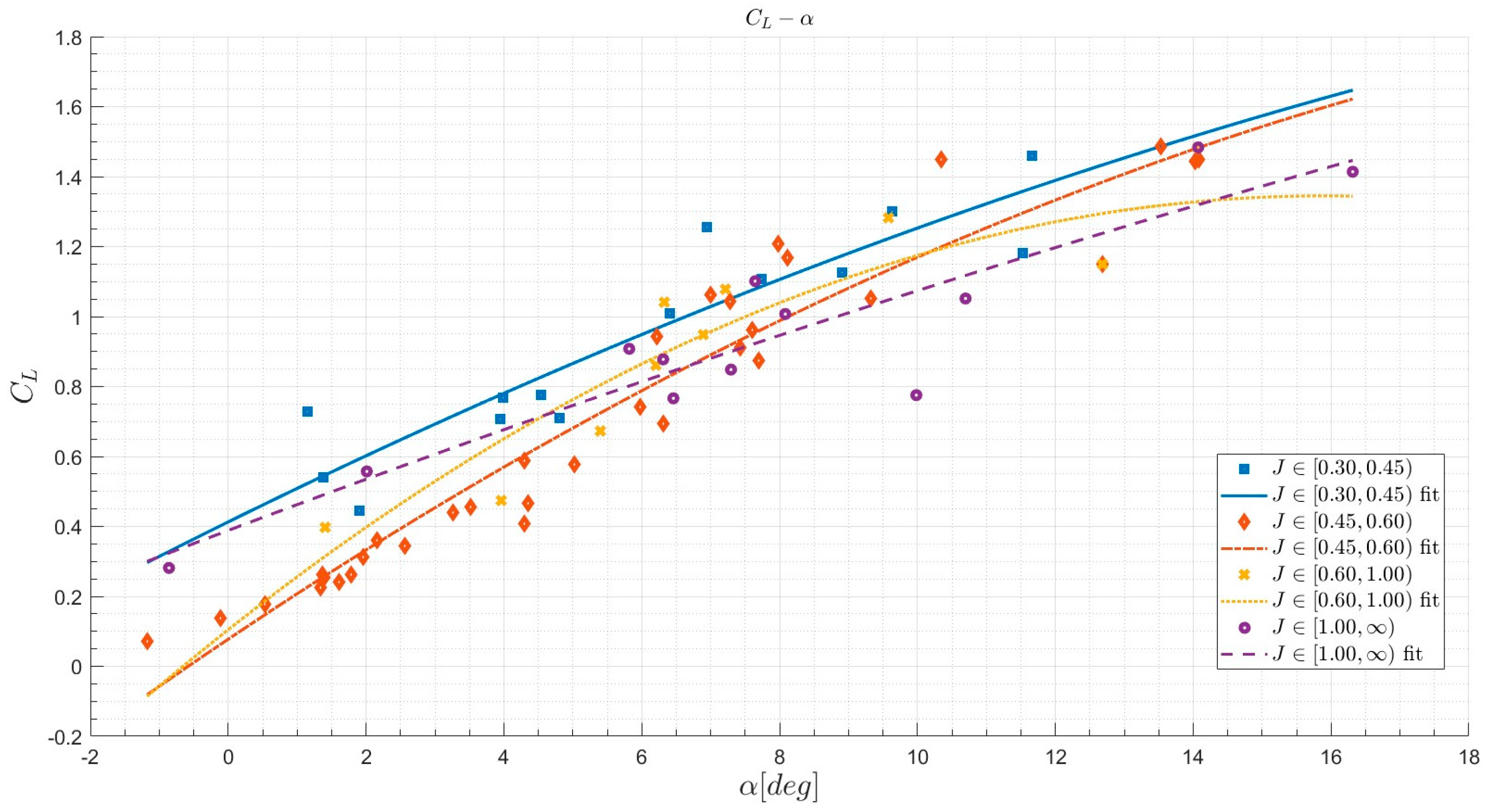
From the curves in Figure 1, divided into four clusters of , it can be observed that the propeller blowing effect tends to shift the curves upwards as decreases, hence enhancing the lifting capability. Also, the curve’s slope is slightly increased as blowing intensifies. This behavior seems to confirm that the propeller slipstream, by locally accelerating the airflow over the wing, increases the local dynamic pressure, resulting in enhanced lift generation at any angle of attack.
Figure 1.
curves divided into clusters.
However, a more peculiar behavior emerges at low angles of attack (), where the for the unblown condition appears slightly higher than for intermediate blowing settings (), suggesting a complex aero-propulsive interaction at low values that deviates from the purely monotonic blowing–lift relationship.
This trend is consistent with the preliminary identification results discussed in [11], where the reference lift coefficient , a dominant parameter in reconstruction, reached a minimum at intermediate blowing levels, with , before recovering toward the unblown regime.
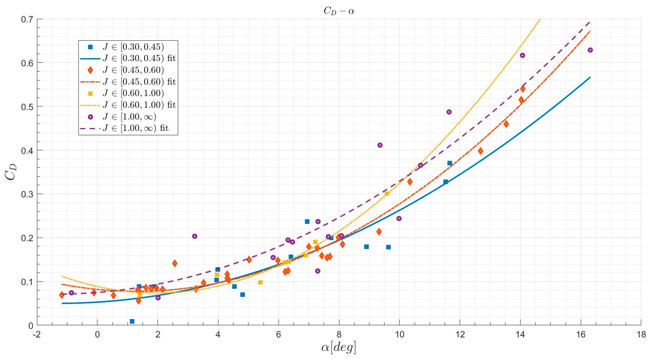
Propeller blowing also seems to produce an effect on the curves, with a downward shift that leads to drag reduction, more evident at high angles of attack but less pronounced than the effect on lift.
A possible explanation is that, while the increased dynamic pressure in the propeller slipstream raises the local parasitic drag on the blown wing, at the same time, the outer propellers counteract the effect of wingtip vortices by rotating in the opposite direction, leading to a reduction in lift-induced drag. This effect would be more evident at high angles of attack, since the induced drag depends on the square of the lift coefficient.
This phenomenon has already been documented in prior studies and is exploited in some DEP concepts, such as the NASA X-57 Maxwell [17], where wingtip propellers are used in the cruise phase to reduce the induced drag. The slight downward shift in the curves could reflect the partial balance between changes in parasitic and induced drag.
However, due to the nature of the flight-test-based approach, we cannot state confidently whether this is the major cause of drag reduction or whether other aero-propulsive effects arise, and only preliminary hypotheses about the observed behavior can be made.
Also in this case, non-monotonic behavior is observed, especially at intermediate values between and , as shown in Figure 2.
Figure 2.
curves divided into clusters.
3.2. Trimmed Aerodynamic Polars
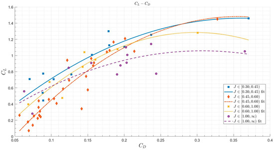
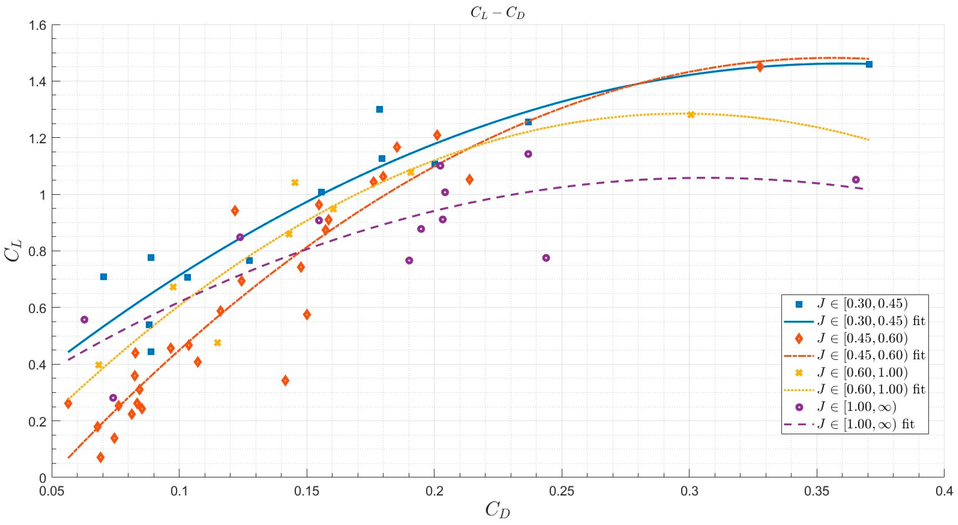
As a consequence of the aerodynamic identification, the trimmed aerodynamic polars were plotted to summarize all the previous results, as shown in Figure 3. The lift increase and drag reduction effects are clearly visible in the curves, especially at low values of and high angles of attack. As decreases, the polars exhibit a clear upward translation, reflecting the significant increase in lift, while a marginal leftward shift indicates a slight drag reduction. This results in the ratio increase, which means that the overall aerodynamic efficiency is improved in high-blowing and medium-to-high lift ranges, while the unblown condition appears to be slightly more efficient than intermediate blowing settings, when evaluated at low values.
Figure 3.
trimmed aerodynamic polars divided into clusters.
This supports the non-monotonic behavior at low values, which was partially expected from previous identification results but at the same time prevents straightforward predictions about the aerodynamic dependence on blowing in that condition.
However, it should be noted that the data points displayed in the graphs exhibit considerable scatter, reflecting the current limitations of the experimental framework. The analytical fittings are intended to provide a representative trend, primarily where the local coefficients (derived from individual test points) are densely populated. Consequently, in the extreme regions of the plots where fewer data points are available, the curves are characterized by lower statistical confidence and should be interpreted with caution.
4. Conclusions
The present contribution provides a preliminary flight-test-based identification of the aero-propulsive behavior of a DEP aircraft, with a focus on the blowing effect on trimmed aerodynamic polars. Complex and nonlinear aero-propulsive coupling was frequently observed, especially at intermediate values, but at the same time, the obtained results support the beneficial effect of distributed blowing, providing experimental confirmation of the performance trends predicted by previous numerical and experimental studies [8,11]. Although the complex interaction at low incidence seems to slightly penalize intermediate blowing settings, the results support the significant aerodynamic advantages typically expected for blown-wing DEP configurations, particularly in high-lift conditions.
However, the results presented in this contribution represent qualitative trends and preliminary findings, which will be enriched with more detailed analyses, quantitative data, and validation metrics in forthcoming publications.
Author Contributions
Conceptualization, G.F., S.C. and C.E.D.R.; methodology, G.F., S.C. and L.T.; software, B.M.P.; validation, G.F., S.C. and B.M.P.; formal analysis, G.F. and S.C.; writing—original draft preparation, G.F. and B.M.P.; writing—review and editing, S.C. All authors have read and agreed to the published version of the manuscript.
Funding
This research received no external funding.
Institutional Review Board Statement
Not applicable.
Informed Consent Statement
Not applicable.
Data Availability Statement
The dataset generated during the flight test missions can be requested via e-mail to the corresponding authors.
Acknowledgments
The authors would like to thank Lorenzo Massa and Niko Terzaroli for their support in the development and testing activities, and Davide Pasquali for his role as test pilot during the flight campaign.
Conflicts of Interest
The authors declare no conflicts of interest.
Abbreviations
The following abbreviations are used in this manuscript:
| DEP | Distributed Electric Propulsion |
| LI | Local Identification |
| MAVLink | Micro Air Vehicle Communication Protocol |
| PX4 | PX4 Autopilot |
| TECS | Total Energy Control System |
Nomenclature
The following symbols are used in this manuscript:
| Angle of attack | |
| Flight path angle | |
| Elevator deflection | |
| Drag coefficient | |
| Lift coefficient | |
| Pitch moment coefficient | |
| Thrust coefficient | |
| Propeller diameter | |
| Propeller advance ratio | |
| Propeller rotational speed | |
| Pitch angular rate | |
| Airspeed |
References
- Hoogreef, M.F.M.; de Vries, R.; Sinnige, T.; Vos, R. Synthesis of aero-propulsive interaction studies applied to conceptual hybrid-electric aircraft design. In Proceedings of the AIAA Scitech 2020 Forum, Orlando, FL, USA, 6–10 January 2020. [Google Scholar] [CrossRef] [Scilit]
- Kim, H.D.; Perry, A.T.; Ansell, P.J. A Review of Distributed Electric Propulsion Concepts for Air Vehicle Technology. In Proceedings of the 2018 AIAA/IEEE Electric Aircraft Technologies Symposium (EATS), Cincinnati, OH, USA, 12–13 July 2018. [Google Scholar] [CrossRef] [Scilit]
- Patterson, M.D.; German, B.J.; Moore, M.D. Performance Analysis and Design of On-Demand Electric Aircraft Concepts. In Proceedings of the 12th AIAA Aviation Technology, Integration, and Operations (ATIO) Conference, Indianapolis, Indiana, 17–19 September 2012. [Google Scholar] [CrossRef] [Scilit]
- Cao, M.; Liu, K.; Wang, C.; Wei, J.; Qin, Z. Research on the Distributed Propeller Slipstream Effect of UAV Wing Based on the Actuator Disk Method. Drones 2023, 7, 566. [Google Scholar] [CrossRef] [Scilit]
- Nicolosi, F.; Idioma, D.; Ciliberti, D.; Della Vecchia, P. Experimental Assessment of Aero-Propulsive Effects on a Commuter Aircraft due to Distributed Electric Propulsion. In Proceedings of the 10th CEAS Aerospace Europe Conference/28th AIDAA International Congress, Turin, Italy, 1–4 December 2025. [Google Scholar]
- Christopher, B.; Courtin, R.; Hansman, J.; Drela, M. Flight Test Results of a Subscale Super-STOL Aircraft; Report No. ICAT-2020-01; MIT, International Center for Air Transportation: Cambridge, MA, USA, 2020. [Google Scholar]
- Trainelli, L.; Riboldi, C.E.D.; Cacciola, S. Design, Implementation and Testing of a Distributed Electric Propulsion Demonstrator. In Proceedings of the 34th Society of Flight Test Engineers European Chapter Symposium, Rome, Italy, 16–18 May 2023. [Google Scholar]
- Cacciola, S.; Bottà, L.; Riboldi, C.E.D.; Trainelli, L. Identification of the Impact of Blowing on the Aerodynamic Model of an Airplane with Distributed Electric Propulsion. In Proceedings of the 34th ICAS Congress, Florence, Italy, 9–13 September 2024; Available online: https://www.icas.org/icas_archive/icas2024/data/papers/icas2024_1134_paper.pdf (accessed on 30 May 2026).
- Cacciola, S.; Filippoli, G.; Perri, B.M.; Riboldi, C.E.D.; Terzaroli, N.; Trainelli, L. Autonomous Flight Tests of a Distributed Electric Propulsion Demonstrator Based on a Total Energy Control System. In Proceedings of the 11th European Conference for Aeronautics and Aerospace Sciences (EUCASS), Rome, Italy, 30 June–4 July 2025. [Google Scholar] [CrossRef]
- Trainelli, L.; Filippoli, G.; Terzaroli, N.; Perri, B.M.; Cacciola, S.; Riboldi, C.E.D. Automated Flight Testing of a Distributed Electric Propulsion Flying Model. In Proceedings of the 10th CEAS Aerospace Europe Conference/28th AIDAA International Congress, Turin, Italy, 1–4 December 2025. [Google Scholar]
- Filippoli, G.; Terzaroli, N.; Perri, B.M.; Massa, L.; Trainelli, L.; Cacciola, S.; Riboldi, C.E.D. Aero-Propulsive Modeling and System Identification of a Distributed Electric Propulsion Flying Model. In Proceedings of the 10th CEAS Aerospace Europe Conference/28th AIDAA International Congress, Turin, Italy, 1–4 December 2025. [Google Scholar]
- Lambregts, A.A. TECS Generalized Airplane Control System Design—An Update. In Advances in Aerospace Guidance, Navigation and Control, Proceedings of the 2013 CEAS Conference on Guidance, Navigation and Control, Delft, The Netherlands, 2013; Springer: Berlin/Heidelberg, Germany, 2013. [Google Scholar] [CrossRef] [Scilit]
- Kimberlin, R.D. Flight Testing of Fixed-Wing Aircraft; AIAA Education Series; American Institute of Aeronautics and Astronautics: Reston, VA, USA, 2003. [Google Scholar]
- Filippoli, G.; Perri, B.M.; Terzaroli, N.; Trainelli, L.; Cacciola, S.; Riboldi, C.E.D. Development of an Autonomous Flight Control System for a Distributed Electric Propulsion Flying Model. In Proceedings of the 10th CEAS Aerospace Europe Conference/28th AIDAA International Congress, Turin, Italy, 1–4 December 2025. [Google Scholar]
- Pamadi, B.N. Performance, Stability, Dynamics, and Control of Airplanes; American Institute of Aeronautics and Astronautics: Reston, VA, USA, 2004. [Google Scholar]
- Klein, V.; Morelli, E.A. Aircraft System Identification: Theory and Practice; American Institute of Aeronautics and Astronautics: Reston, VA, USA, 2006. [Google Scholar]
- Litherland, B.L.; Borer, N.K.; Zawodny, N.S. X-57 “Maxwell” High-Lift Propeller Testing and Model Development. In Proceedings of the AIAA Aviation 2021 Forum, Online, 2–6 August 2021. [Google Scholar] [CrossRef]
Disclaimer/Publisher’s Note: The statements, opinions and data contained in all publications are solely those of the individual author(s) and contributor(s) and not of MDPI and/or the editor(s). MDPI and/or the editor(s) disclaim responsibility for any injury to people or property resulting from any ideas, methods, instructions or products referred to in the content. |
© 2026 by the authors. Licensee MDPI, Basel, Switzerland. This article is an open access article distributed under the terms and conditions of the Creative Commons Attribution (CC BY) license.