


Abstract
This paper presents a comparative analysis of Flywheel Energy Storage Systems (FESS) employing Permanent Magnet Synchronous Machines (PMSMs) and AC Brushless DC (AC-BLDC) machines for fast and efficient frequency regulation. The study examines their electromechanical behavior during the key operational stages of charging, standby, and discharging, with a focus on mitigating inrush current and enhancing overall system efficiency. MATLAB/Simulink models were developed to evaluate machine dynamics, electromagnetic behavior, and harmonic distortion during their operation. The results show that electromagnetic effects, particularly inrush current, commutation harmonics, and inverter limitations, significantly influence torque smoothness, efficiency, and overall system performance. PMSMs demonstrate superior torque quality, lower Total Harmonic Distortion (THD), and more stable energy conversion under Field-oriented Control (FOC), making it well suited for high-performance FESS applications. In contrast, the AC-BLDC machine exhibits higher torque ripple and elevated THD due to six-step commutation but offers a simpler drive topology and cost advantages. The findings offer practical insights for selecting machines and controllers in high-speed FESS designs and emphasize the importance of mitigating transient electromagnetic effects to enhance efficiency and reliability in modern grid support applications. Improved modeling incorporating magnetic saturation, frequency-dependent iron losses, and inverter constraints is essential for accurate performance prediction. Future work includes Hardware-In-the-Loop (HIL), Power-HIL validation, and DlgSILENT PowerFactory co-simulation to confirm dynamic performance under grid-connected operation.
1. Introduction
The increasing integration of renewable energy resources into modern power systems has introduced new challenges to maintaining frequency stability and grid reliability. Since inverter-based generation lacks the inherent inertia of conventional synchronous machines, the power grid has become more vulnerable to rapid frequency deviations caused by fluctuating generation and load patterns [1]. To address this, Energy Storage Systems (ESS) have become an indispensable part of the modern energy landscape, providing fast response and bidirectional power capabilities to balance generation and demand [2].
Among the available ESS technologies, Flywheel Energy Storage Systems (FESS) have gained significant attention for their high power density, long cycle life, and rapid charge–discharge capabilities [3]. FESS units are particularly effective for short-term frequency support, grid stabilization, and load leveling due to their ability to exchange large amounts of power within milliseconds. The core of an FESS lies in its electromechanical conversion system, where a high speed electrical machine, often either a Permanent Magnet Synchronous Machine (PMSM) or an AC Brushless DC (AC-BLDC) machine, is mechanically coupled to a flywheel rotor to store and release kinetic energy [4].
While numerous studies have focused on improving the efficiency and control performance of PMSM and BLDC based flywheel systems, most have prioritized steady-state operation and loss minimization without fully addressing dynamic transients during startup and mode transitions. Since FESS units operate continuously in response to grid frequency variations, they experience frequent charging and discharging sequences, often requiring rapid mode changes between motoring and generating states. These transitions induce inrush currents, large transient surges occurring when the machine accelerates from rest or re-engages with the grid after a standby period. Such inrush events cause converter overcurrent stress, magnetic saturation, and torque pulsations, which can degrade overall system reliability and efficiency [4].
Despite its importance, the mitigation of inrush current in high-speed FESS applications remains insufficiently addressed in the current literature. Traditional soft-start methods used in industrial drives are not always compatible with fast dynamic requirements and high inertia levels of flywheel systems. Hence, there is a growing need for advanced control-oriented design strategies that can simultaneously manage torque dynamics and limit inrush current magnitude during startup and transient operation.
In this context, this paper presents a comprehensive design and efficiency analysis of FESS employing PMSM and AC-BLDC machines, incorporating both steady-state efficiency mapping and transient current behavior analysis. Detailed electromechanical and thermal models are developed using MATLAB/Simulink to evaluate performance under variable speed and torque conditions. Furthermore, a novel control-oriented design approach is proposed to reduce inrush current during motor startup, improving converter reliability and overall system efficiency. The findings contribute valuable insights toward the optimal selection and operation of machine topologies for next-generation high-speed FESS applications in grid frequency regulation and renewable energy integration.
The proposed 100 kW FESS integrates either a PMSM or an AC-BLDC machine as the electromechanical converter. Both topologies are coupled to a high-speed flywheel rotor via a low-friction shaft supported by magnetic bearings. The machine is connected to a bidirectional voltage source inverter, which regulates the electromagnetic torque and rotor speed based on the grid frequency requirements.
2. PMSM and AC-BLDC Machines in FESS
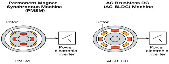
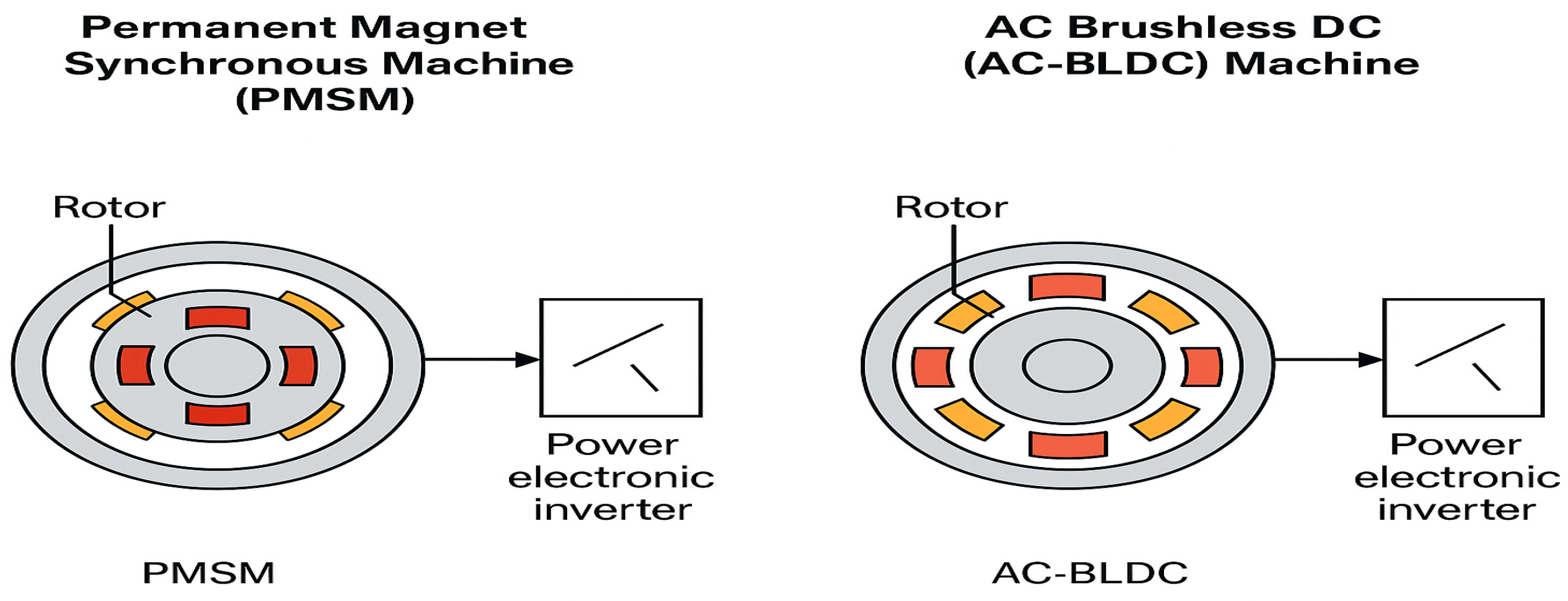
The choice of the electric machine significantly influences the overall efficiency, control performance, and cost of an FESS. PMSMs shown in Figure 1 are widely used due to their high torque density, excellent efficiency, and precise controllability, especially under vector control schemes [5]. PMSMs allow efficient bidirectional operation with reduced copper and iron losses, making them suitable for high-speed FESS applications [6]. Conversely, AC Brushless DC (BLDC) machines, Figure 1, which share structural similarities with PMSMs but rely on trapezoidal back-EMF and six-step commutation, offer simpler control and reduced cost [7]. These two machines are mostly used in machine applications; their robust construction and lower switching losses make them appealing for compact flywheel systems where cost and simplicity are prioritized [8].
Figure 1.
Structure of the PMSMs and AC-BLDC machines [9].
3. Efficiency Optimization and Control Strategies
Efficiency optimization in FESS depends not only on machine design but also on converter topology and control strategy. Techniques such as FOC and Direct Torque Control (DTC) have been widely used to enhance dynamic response and minimize losses in PMSM-based systems [10]. For BLDC-driven FESS, torque ripple minimization and commutation optimization remain critical research areas to ensure smoother power exchange and higher system efficiency [11]. Comparative studies indicate that while PMSM-based FESS achieve higher energy efficiency, BLDC-based systems offer advantages in fault tolerance and maintenance [7]. The selection between PMSM and BLDC thus depends on the intended application, speed range, and cost–performance trade-offs.
4. System Modeling and Design Methodology
The overall FESS consists of a high-speed rotating flywheel coupled with an electrical machine (either PMSM or AC-BLDC), a bidirectional power converter, and a control unit that manages charge and discharge operations. The modeling framework aims to capture the electromechanical dynamics, energy conversion efficiency, and loss mechanisms of both topologies under dynamic operation. The flywheel stores energy in the form of kinetic energy [12], expressed as in (1):
where is the stored energy in kWh, J is the moment of inertia of the PMSM machine rotor system in . It quantifies the resistance of the rotor to changes in rotational speed. is the rotor angular speed in rad/s. The rate of change of stored energy can be expressed as shown in (2):
where is the mechanical torque delivered by the machine N.m and represents parasitic losses (windage, bearing, and frictional losses) in kW. The mechanical dynamics of the flywheel are governed by (3)
where is the electromagnetic torque, is the load torque (positive during discharge), and represents frictional torque losses, which can be approximated as shown (4):
where is the viscous damping coefficient, and is the Coulomb friction torque.
4.1. PMSM Model
The PMSM exhibits sinusoidal back-electromotive force (EMF) and produces smooth torque, modeled in the d–q rotating reference frame, is shown in (5) [7].
where , are stator voltages; , are currents; , are inductances; is the stator resistance; is the electrical angular speed; and is the flux linkage of the rotor permanent magnets. The electromagnetic torque is given by (6)
where p is the number of pole pairs. Under FOC, ( = 0) is enforced for maximum torque per ampere operation [5].
To handle the near-zero speed, the torque-to-current mapping was divided by the nominal speed of the machine ω, for power control will be conditioned; the speed control was used instead (command torque) of pre-defined current limits that were used in [13]. Furthermore, to handle field weakening for speeds above base, we allowed negative id to weaken flux (only for PMSM designs rated for it), and the DC-link was used for regeneration of braking when the speed reached the minimum speed to keep synchronizing, instead of a dump resistor and a chopper used in [14].
4.2. AC-BLDC Model
The AC Brushless DC Machine (AC-BLDC) features trapezoidal back-EMF and operates under six-step commutation control as [7]. Its phase voltage equations are given by (7):
where , , represent the back-EMF of each phase defined as in (8), , , are the terminal voltages, and is the resistance, L is the inductance , , and are the terminal currents in the abc reference frame.
with denoting the trapezoidal waveform function depending on rotor position (). The electromagnetic torque can be expressed as shown (9) [7]:
AC-BLDC control uses hall-effect sensors for commutation and typically exhibits torque ripple due to the non-sinusoidal nature of its back-EMF. Rotor encoder/resolver (high resolution), phase currents (shunts), DC-link voltage, inverter temperature, vibration/accelerometer for rotor health. Sample rates: inner current loop in hardware at PWM rate (e.g. 10–20 kHz); speed loop at 1–5 kHz or 200–1000 Hz (2 ms recommended); supervisory at 10–100 Hz. State estimation: filter measured speed (low-latency PLL or digital filter) and current (low-pass), but avoid too much phase lag for droop/VSG.
4.3. Converter and Control Strategy
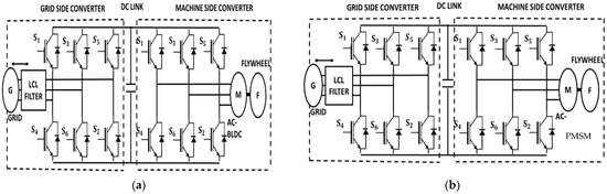
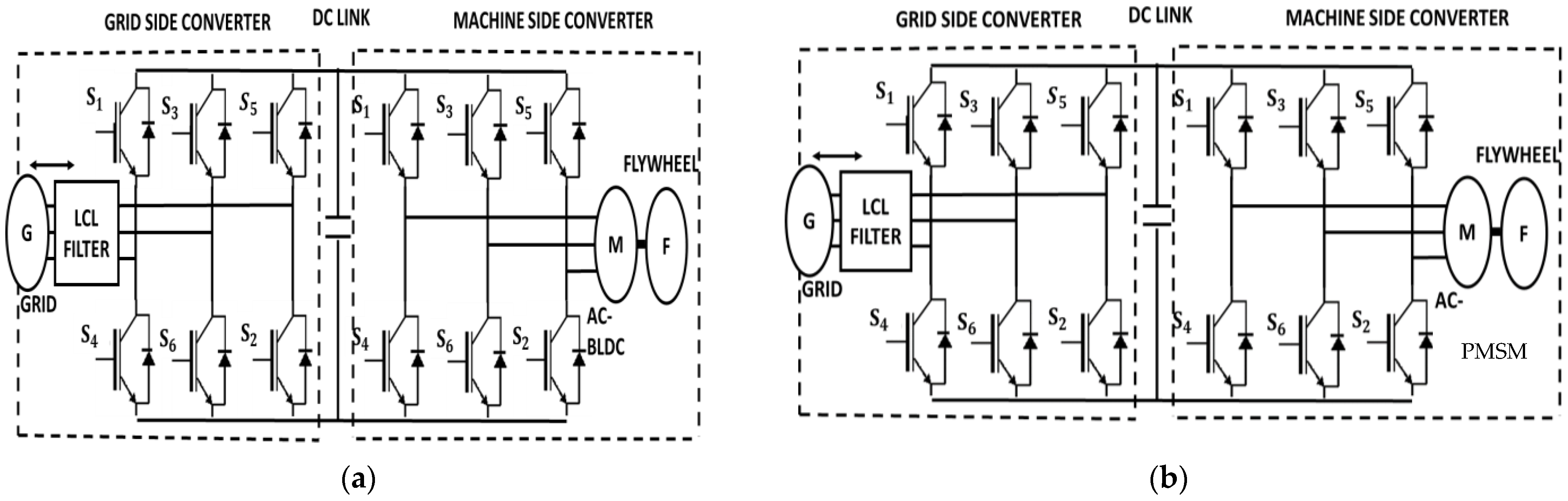
Both PMSM and AC-BLDC systems are interfaced with a bidirectional voltage-source inverter (VSI) as shown in Figure 2a,b, enabling charge (motor) and discharge (generator) modes. The converter losses are modeled as a combination of conduction and switching losses as shown in (10):
where is the number of switches, is the forward voltage drop, is the switch current, Esw is the switching energy per cycle, and fs is the switching frequency [15].
Figure 2.
(a) Voltage source inverter coupling the AC BLDC machine to the AC Grid; (b) voltage source inverter coupling the PMSM to the AC grid.
The appropriate control strategy employs FOC for the PMSM and trapezoidal current control (TCC) for the AC-BLDC machine. Both strategies are implemented in MATLAB/Simulink with a cascaded control structure comprising speed, current, and torque loops to regulate energy transfer between the grid and the flywheel. A similar control strategy of a DC motor can be found in [13].
4.4. Efficiency and Loss Analysis
The total system efficiency is derived as the ratio of mechanical energy retrieved to the electrical energy input, as shown in (11):
Loss components include (copper losses), (iron losses), (converter losses as defined above), and (windage and bearing losses) as shown in (12).
Efficiency maps are generated across different speed–torque operating points for both PMSM and AC-BLDC configurations. These maps are then used to evaluate the optimal operating zones and system-level energy conversion efficiency during charge–discharge cycles.
4.5. Speed Control Challenges of PMSM and AC-BLDC Machines for Flywheel Energy Storage Systems
The control of FESS using high-speed electrical machines such as the PMSM and the AC-BLDC motor is complex due to nonlinear dynamics, efficiency constraints, and operational transitions. These challenges arise because the FESS must rapidly charge, store, and discharge energy while maintaining stable grid frequency and minimizing mechanical and electrical losses.
4.6. Nonlinear Dynamics and Parameter Sensitivity
Both PMSM and BLDC machines exhibit nonlinear torque–speed relationships and parameter dependency. Small deviations in stator resistance, inductance, or magnetic flux linkage significantly affect dynamic torque response, particularly during high-speed operation. PMSMs require decoupled control of the d–q currents through FOC, where cross-coupling effects can destabilize the inner current loop if not properly compensated. In BLDC systems, the non-sinusoidal back-EMF leads to commutation-induced torque ripple, which increases stress on the flywheel and reduces control accuracy [16].
4.7. High-Speed Operation and Inverter Limitations
Operating at speeds above 15,000 rpm introduces additional inverter challenges. Voltage saturation, finite PWM switching frequency, and dead-time distortions cause phase delay and limit torque-producing current accuracy. PMSM drives require precise flux-weakening control to maintain torque capability under voltage constraints, while AC-BLDC systems depend on accurate commutation timing to prevent phase lag and torque pulsations [17].
5. Torque Ripple and Harmonic Distortion
PMSM drives generally provide smooth torque, but saturation and magnetic saliency may induce harmonic distortion at high load. In contrast, BLDC drives inherently produce torque ripple due to trapezoidal back-EMF and discontinuous current conduction. These torque oscillations can excite mechanical resonances in the flywheel shaft. Mitigation strategies include current shaping, harmonic injection, and predictive torque control [18].
5.1. Mode Transition and Bidirectional Power Flow
An FESS continuously switches between motoring (charging), standby, and generating (discharging) modes. During these transitions, current and torque commands must be aligned to avoid overshoot or instability. PMSM systems use synchronized reference frame alignment for flux weakening, while BLDC systems rely on accurate rotor position detection and regenerative braking control. These aspects are crucial for maintaining smooth bidirectional power flow [19].
5.2. Thermal and Efficiency Management
Continuous high-speed operation introduces significant thermal stress. PMSM magnets are vulnerable to partial demagnetization at elevated temperatures, whereas BLDC drives face copper losses due to rectangular current profiles. Advanced cooling and loss minimization control strategies are often employed to sustain high efficiency under varying load cycles [20].
5.3. Sensorless Control and Fault Tolerance
To reduce cost and improve reliability, sensorless estimation of rotor position is increasingly used. However, in both PMSM and BLDC drives, sensorless algorithms exhibit poor accuracy at low speeds due to weak back-EMF signals. Fault-tolerant control, particularly during inverter switch failure or unbalanced phases, remains a challenge that requires adaptive algorithms and redundancy [18].
6. Inrush Current Characterization and Mitigation Strategy
The design of the PMSM and AC-BLDC machine drives, when the FESS charges, the stator windings have to be energized, with low back-EMF disturbance, and inverter dead time. We have to approximate the machine’s instantaneous current during startup by (13) as discussed in [21].
where is the inverter DC-link voltage, Ls is the stator inductance, and is the stator resistance. This model forms the basis for developing a current-limiting control loop, which dynamically adjusts the reference voltage vector according to the following condition (14):
where is the predefined time constant optimized to limit peak current below 1.5 rated value without compromising torque response.
7. Simulation and Operation Modes
The simulation results using the parameters of FESS with PMSM and AC-BLDC machines are presented in Table 1, demonstrating how electromagnetic machine behavior fundamentally shapes the FESS dynamics during charging, standby, and discharging. During charging, the near-zero back-EMF at standstill permits rapid current rise and a strong torque impulse, which is limited in practice by control and inverter constraints; magnetic saturation may further reduce incremental torque at high currents. In standby, small q-axis currents suffice to balance viscous and bearing losses, but iron and harmonic losses (from PWM and commutation) continue to consume energy, an effect that must be captured with frequency-dependent iron-loss models.
Table 1.
FESS parameters with PMSM and AC-BLDC machines.
During discharging, back-EMF governs regeneration capability and, combined with inverter limits, determines how aggressively stored kinetic energy can be dispatched. PMSM drives deliver smoother torque and lower harmonic loss under FOC, while AC-BLDC machines exhibit higher torque ripple and harmonic content due to trapezoidal back-EMF and commutation; these electromagnetic distinctions influence the observed differences in acceleration, peak currents, and energy throughput. Full switching level and electromagnetic (saturation, iron-loss) models are recommended to quantify these effects precisely.
8. Results and Discussion: Machine Performance Across Charging, Standby, and Discharging Stages
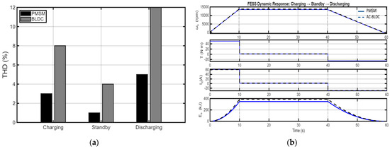
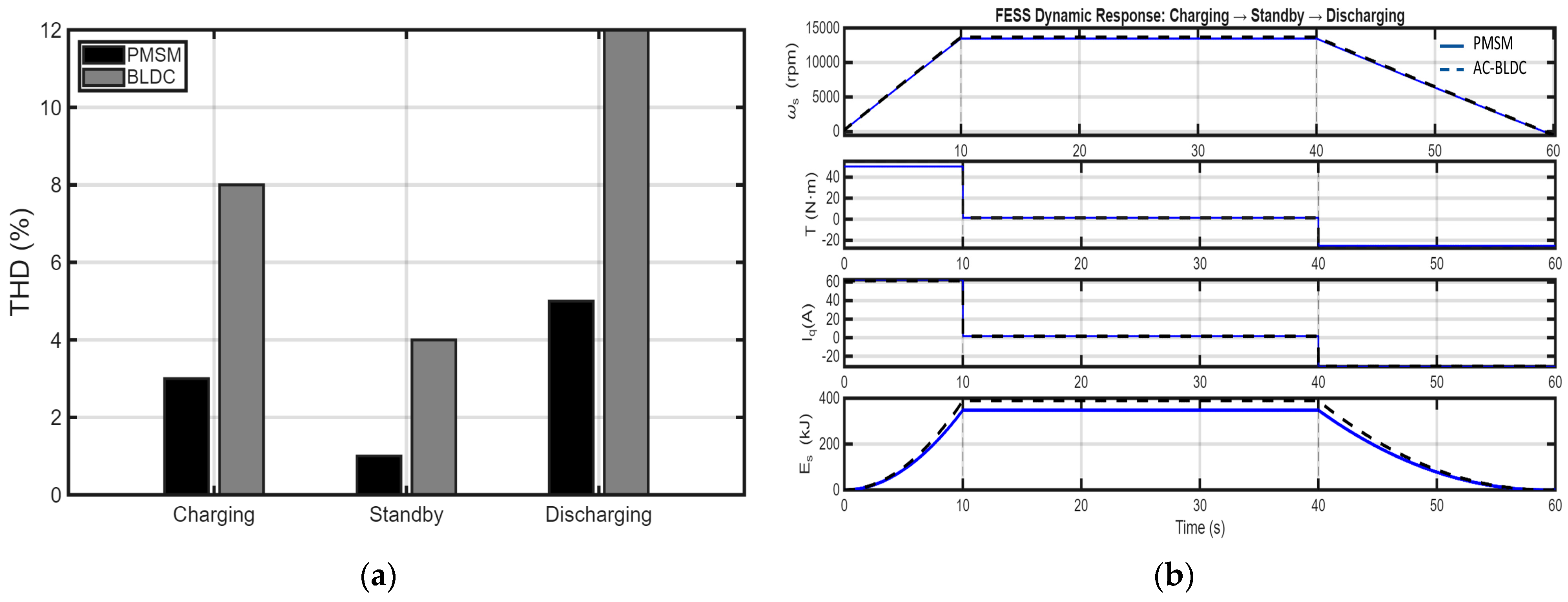
It can be observed from Figure 3a,b that, across all operating stages, charging, standby, and discharging, the PMSM and AC-BLDC machines exhibit distinct electromagnetic and harmonic behaviors that directly influence FESS performance. During the charging stage, both machines experience high inrush currents due to low back-EMF at rest, resulting in transient torque overshoot and elevated THD. The PMSM handles this transition smoothly with lower current distortion, while the BLDC presents considerably higher THD caused by six-step commutation and current overlap. These results highlight the need for soft-start or current-limiting strategies to mitigate electromagnetic stress and protect converter components.
Figure 3.
(a) Comparison of THD of PMSM and AC-BLDC machine; (b) PMSM and AC-BLDC machine speed, torque, current, and energy variation.
In the standby stage, the PMSM maintains very low THD and highly stable current owing to its sinusoidal excitation and negligible torque demand. Conversely, the BLDC continues to exhibit moderate THD even under no-load conditions, driven by commutation switching harmonics. Both machines display measurable standby losses, underscoring the importance of optimized control strategies for minimizing parasitic losses during prolonged storage periods.
During the discharging stage, the PMSM provides smooth regenerative torque and moderate THD primarily constrained by inverter voltage limits. The BLDC, however, produces higher THD due to commutation overlap during regeneration, which increases switching stress and torque ripple. Overall, PMSM offers more stable and predictable energy release, whereas the BLDC requires additional harmonic mitigation to achieve comparable performance.
Overall, both machines can perform energy absorption and release effectively; however, their electromagnetic characteristics produce distinct behaviors. The PMSM delivers smooth torque, sinusoidal currents, and low THD under FOC, making it well suited for continuous and grid-forming applications. In contrast, the BLDC exhibits higher torque ripple, commutation-induced harmonics, and elevated THD, though it offers a simpler inverter structure and potential cost benefits.
9. Conclusions and Recommendation
This study compared the performance of FESS using PMSM and AC-BLDC machines across undercharging, standby, and discharging conditions. MATLAB/Simulink simulations were used to evaluate electromechanical behavior, efficiency, and harmonic performance. To improve the performance of PMSM and AC-BLDC-based FESS, soft-start or current-limiting methods are recommended to reduce inrush current and protect the converter during charging. Harmonic mitigation strategies, particularly for BLDC drives, should be implemented to address their higher THD resulting from commutation effects. More accurate machine modeling that includes magnetic saturation, iron losses, and inverter constraints is essential for capturing real electromagnetic behavior. Standby losses can be minimized through optimized idle-mode control that reduces unnecessary excitation.
Overall, PMSM remains the preferred option for high-performance, low-distortion FESS applications, while BLDC machines may be used in cost-sensitive systems provided that harmonic mitigation is properly addressed. Include nonlinear magnetic saturation, frequency-dependent iron losses, and inverter voltage constraints in the simulation to capture real machine behavior more accurately. Perform hardware-in-the-loop or laboratory testing to validate the simulation models, focusing on startup transients, torque ripple, and regenerative performance. Validate the developed MATLAB model using DigSILENT PowerFactory to ensure consistent dynamic performance in grid-connected operation, and implement the PHIL.
Author Contributions
The conceptualization, methodology, software, validation, investigation, data curation, and writing review, writing original draft preparation, and editing were carried out by W.S.N. and J.V.C. The formal analysis, resources, project administration, and funding acquisition were carried out by C.G. All authors have read and agreed to the published version of the manuscript.
Funding
This research received no external funding.
Informed Consent Statement
Not applicable.
Data Availability Statement
The MATLAB/Simulink simulation models and data supporting the findings of this study are available from the corresponding author upon reasonable request.
Acknowledgments
During the preparation of this manuscript/study, the author(s) used [Matlab/Simulink, 2025a] and Grammarly, respectively, for the purposes of [simulation] and proofreading. The authors have reviewed and edited the output and take full responsibility for the content of this publication. We would like to thank Witwatersrand University and the Vaal University of Technology, and our family.
Conflicts of Interest
The authors declare no conflicts of interest. The funders had no role in the design of the study; in the collection, analyses, or interpretation of data; in the writing of the manuscript; or in the decision to publish the results.
Abbreviations
The following abbreviations are used in this manuscript:
| AC-BLDC | AC Brushless DC |
| DTC | Direct Torque Control |
| EMF | Electromotive Force |
| FESS | Flywheel Energy Storage Systems |
| FOC | Field-oriented Control |
| HIL | Hardware-in-the-loop |
| PMSM | Permanent Magnet Synchronous Machines |
| TCC | Trapezoidal Current Control |
| THD | Total Harmonic Distortion |
References
- Hadavi, A.; Hagh, M.T.; Zadeh, S.G. Frequency Stability in Modern Power Systems with 100% Renewable Energy Penetration. Results Eng. 2025, 28, 108168. [Google Scholar] [CrossRef] [Scilit]
- Luo, X.; Wang, J.; Dooner, M.; Clarke, J. Overview of current development in electrical energy storage technologies and the application potential in power system operation. Appl. Energy 2015, 137, 511–536. [Google Scholar] [CrossRef] [Scilit]
- Prince, O.A.; Hu, Y.; Philip, A.; Adam, M. Modeling and performance analysis of a flywheel energy storage system. In Proceedings of the 2015 International Conference on Electromechanical Control Technology and Transportation; Atlantis Press: Zhuhai, China, 2015; pp. 49–54. [Google Scholar]
- Li, W.; Chau, K.; Ching, T.; Wang, Y.; Chen, M. Design of a high-speed superconducting bearingless machine for flywheel energy storage systems. IEEE Trans. Appl. Supercond. 2014, 25, 5700204. [Google Scholar] [CrossRef] [Scilit]
- Boztas, G.; Aydogmus, O. Design of a high-speed PMSM for flywheel systems. In Proceedings of the 2019 4th International Conference on Power Electronics and their Applications (ICPEA); IEEE: Piscataway, NJ, USA, 2019; pp. 1–5. [Google Scholar]
- Zang, B.; Chen, Y. Multiobjective optimization and Multiphysics design of a 5 MW high-speed IPMSM used in FESS based on NSGA-II. IEEE Trans. Energy Convers. 2022, 38, 813–824. [Google Scholar] [CrossRef] [Scilit]
- Saadat, H. Power System Analysis, 3rd ed.; McGraw-Hill: New York, NY, USA, 2010; pp. 1–720. [Google Scholar]
- Takarli, R.; Amini, A.; Khajueezadeh, M.; Zarbil, M.S.; Vahedi, A.; Kiyoumarsi, A.; Tarzamni, H.; Kyyra, J. A comprehensive review on flywheel energy storage systems: Survey on electrical machines, power electronics converters, and control systems. IEEE Access 2023, 11, 81224–81255. [Google Scholar] [CrossRef] [Scilit]
- Miller, T.J.E. Brushless Permanent-Magnet and Reluctance Motor Drives; Clarendon Press: Oxford, UK, 1989. [Google Scholar]
- Lu, Y.; Jiang, Z.; Chen, C.; Zhuang, Y. Energy efficiency optimization of field-oriented control for PMSM in all electric system. Sustain. Energy Technol. Assess. 2021, 48, 101575. [Google Scholar] [CrossRef] [Scilit]
- Chen, W.; Liu, Y.; Li, X.; Shi, T.; Xia, C. A novel method of reducing commutation torque ripple for brushless DC motor based on Cuk converter. IEEE Trans. Power Electron. 2016, 32, 5497–5508. [Google Scholar] [CrossRef] [Scilit]
- Gambôa, P.; Silva, J.F.; Pinto, S.F.; Margato, E. Predictive Optimal Matrix Converter Control for a Dynamic Voltage Restorer with Flywheel Energy Storage. In Energy Storage in the Emerging Era of Smart Grids; Intech Open: London, UK, 2011. [Google Scholar]
- Ngaha, W.S.; Dorrell, D.; Gomes, C. Flywheel Energy Storage Systems Utilization for Short Duration Power Systems Frequency Stability Support. In Proceedings of the 41st International Power, Automation and Control Technologies (IPACT) Conference, Surabaya, Indonesia, 25–26 September 2025. [Google Scholar]
- Erhan, K.; Özdemir, E. Prototype production and comparative analysis of high-speed flywheel energy storage systems during regenerative braking in hybrid and electric vehicles. J. Energy Storage 2021, 43, 103237. [Google Scholar] [CrossRef] [Scilit]
- Gonzalez, J.; Martinez, S. Control strategies for flywheel energy storage systems: A review. Renew. Sustain. Energy Rev. 2016, 65, 1395–1407. [Google Scholar]
- Rafaq, M.S.; Midgley, W.; Steffen, T. A review of the state of the art of torque ripple minimization techniques for permanent magnet synchronous motors. IEEE Trans. Ind. Inform. 2023, 20, 1019–1031. [Google Scholar] [CrossRef] [Scilit]
- Li, P.; Chen, X. Advanced inverter control for high-speed BLDC drives in flywheel storage systems. IEEE Trans. Ind. Electron. 2020, 67, 6738–6748. [Google Scholar]
- Gao, Q.; Lin, X. Sensorless control and fault diagnosis for high-speed BLDC drives in FESS. IEEE Trans. Power Electron. 2020, 35, 11745–11756. [Google Scholar]
- Nguyen, T.; Zhao, M. Bidirectional control and mode transition in flywheel energy storage systems using PMSM and BLDC machines. IEEE Access 2021, 9, 112345–112358. [Google Scholar]
- Rahman, M.; Abbas, Z. Thermal and efficiency analysis of high-speed PMSM and BLDC for hybrid storage systems. IEEE Trans. Transp. Electrif. 2022, 8, 512–523. [Google Scholar]
- He, J.; Jun, Y.; Gong, B.; Lei, J.; Liu, Y.; Long, F. Analysis of start-up inrush current and its mitigation control strategy. In 2014 IEEE Conference and Expo Transportation Electrification Asia-Pacific (ITEC Asia-Pacific); IEEE: Piscataway, NJ, USA, 2014. [Google Scholar]

Disclaimer/Publisher’s Note: The statements, opinions and data contained in all publications are solely those of the individual author(s) and contributor(s) and not of MDPI and/or the editor(s). MDPI and/or the editor(s) disclaim responsibility for any injury to people or property resulting from any ideas, methods, instructions or products referred to in the content. |
© 2026 by the authors. Licensee MDPI, Basel, Switzerland. This article is an open access article distributed under the terms and conditions of the Creative Commons Attribution (CC BY) license.