


Abstract
With the rising trend of replacing synchronous generators with inverter-based resources, the grid inertia, frequency control, voltage stability, and fault ride-through are compromised. The current research focuses on the coordinated control of Voltage Source Converter-based HVDC (VSC HVDC) and Battery Energy Storage Systems (BESS) for improving the grid stability in the presence of intermittent sources. Two models are created in the MATLAB/Simulink 2025a environment: one for the grid-connected PV system with the addition of BESS in grid-forming mode (GFM) and grid-following mode (GFL), and the other for the multi-terminal HVDC system with the integration of wind energy from the ocean. The results show that the grid-forming converters perform better than grid-following converters in the event of disturbances, and the coordinated control structure aligns with the IEEE 2800-2022 for low-inertia grids.
1. Introduction
The global energy infrastructure is rapidly transitioning to low-carbon electricity supplies with solar photovoltaic and wind technologies increasingly contributing to the overall capacity mix. Although the environmental impacts of these changes are beneficial, the dynamics of the power system are being disrupted. Inverter-based renewables are different from synchronous generators that offer inertia and voltage regulation services as they are typically grid-following [1]. Renewable energy sources with high penetration cause low inertia and short-circuit currents, making the system prone to disturbances. In addition, the distance of the generation sources makes the system management very challenging, requiring the implementation of long-distance transmission systems. VSC-based HVDC systems ensure precise control, asynchronous connection, and strong performance in weak systems [2]. For VSC-HVDC in grid-forming mode, synthetic inertia, voltage, and frequency support are provided. However, the variability in renewable energy requires BESS to provide services like absorbing excess energy, making up deficits, increasing flexibility, minimising curtailment, and regulating frequency [3]. This study proposes a coordinated control strategy for VSC-HVDC and BESS, aiming at improving the grid stability in the face of changing conditions in the power system dominated by renewable energy sources, using advanced control techniques for the converters.
In a conventional electrical grid, voltage and frequency levels are normally maintained within a narrow range by large synchronous machines, which inherently offer inertia, frequency regulation, and reactive power support. The electrical grid’s protection and control systems were also designed with this behaviour in mind, ensuring a stable and efficient electrical system. However, with the increasing share of renewable energy sources, especially wind and solar, in electrical grids, synchronous machines are being replaced. Most of the inverter-based resources behave as grid-following inverters, which do not offer inertia support or voltage control, leading to reduced stability. Moreover, due to the geographical dispersion of renewable energy sources, long-distance transmission is necessary, and for this, HVDC links with advanced controls and energy storage become essential. The increasing gap between the current grid operating state and the optimal state is becoming more visible globally. The higher rates of change of frequency (RoCoF) are increasing the risk of underfrequency load shedding, while voltage instability is becoming more prevalent in weak inverter-dominated grids. If this situation persists, the reliability of the grid will be compromised, which will be detrimental to the investment in renewables and the pace of decarbonization. In 2024, the growth in renewable energy capacity was 585 GW, which is a 15.1% annual growth rate, while solar PV accounted for 42% of the new installations in the year [4]. The share of renewables has crossed 34.5%, while just fifteen years ago, it was less than 20% globally. The plans to triple the capacity of renewables in the coming years are backed by various policy initiatives, such as the EU Renewable Energy Directive [5,6], the US Inflation Reduction Act [7], and India’s Production Linked Incentives [8].
- Grid Stability in Renewable-Dominated Systems
Stability, on the other hand, is described as the capacity of a power system to sustain disturbances and resume normal operating conditions, while still in a state of equilibrium. Thus, a power system is considered to be in a state of stability if all its synchronous machines are still synchronised during a period of abnormal conditions. When a power system operates normally, its power angle is kept constant. However, during a period of disturbances, there is a corresponding acceleration or deceleration of the synchronous machine’s rotor relative to its magnetic field [9]. Such a phenomenon is described by a swing equation, as presented in Equations (1)–(9).
where is the rotor inertia, is the rotor angular velocity, is the power angle, is the mechanical power, and is the electrical power. is referred to as the inertia constant, and is denoted by , and is related to the kinetic energy of the synchronous machines’ rotating masses, :
Reformulating the swing equation in terms of the inertia constant:
Reformulating the swing equation in terms of the electrical quantities , where and is the number of poles.
The swing equation is usually expressed in per unit electrical quantities, using the system power as the base, as shown in Equation (5).
where is the electrical synchronous angular velocity, is the per unit inertia constant defined as . Equation (5) is usually expressed in terms of frequency , where is in degrees, presented in Equation (6).
RoCoF equation [10], the inertial response and available kinetic energy provided by synchronous generators are decreasing both in magnitude and proportion as thermal generation units are retired and IBRs are commissioned. A grid disturbance causes a change in the system’s available kinetic energy, as in Equation (7).
where is the difference between the generated power and the load demand. Equation (7) may be rewritten as Equation (8).
where is the reference angular frequency. As the frequency is proportional to the angular frequency , the frequency terms may be formulated in Equation (9).
where is the nominal grid frequency [10]. This formula illustrates that as the grid disturbance () grows large relative to the available kinetic energy within the system (), the larger the change in frequency for a given disturbance event.
- B.
- Limitations of Inverter-Based Systems
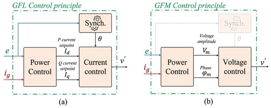
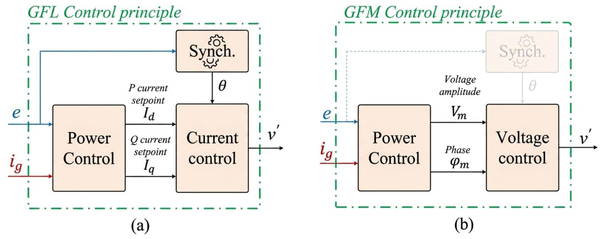
Although inverters are capable of rapid power adjustments, are highly controllable, scalable, and enable compact, modular integration with renewables and energy storage, challenges arise from the fact that most deployed IBRs operate in a grid-following mode. These grid-following (GFL) inverters synchronise to the existing grid voltage and frequency using phase-locked loops (PLLs), meaning they cannot establish voltage or frequency in weak or islanded networks. Their dependency on a stiff grid voltage source makes them vulnerable to voltage dips and instability in low short-circuit ratio (SCR) environments [11]. To address these limitations, grid-forming (GFM) inverters establish their own voltage and frequency reference, making them suitable for weak grids, microgrids, and islanded operation.
Figure 1 presents a variety of control strategies that have been developed to govern the operation of GFM converters. Among the most prominent are droop control, power synchronisation control (PSC), virtual synchronous generator (VSG) or virtual synchronous machine (VSM) control, synchronverter control (SynC), direct power control (DPC), and virtual oscillator control (VOC).
Figure 1.
Simplified (a) GFL control and (b) GFM control [12].
- C.
- Energy Storage Systems
ESSs, especially Battery Energy Storage Systems (BESS), are vital for maintaining grid stability amid high penetration of IBRs. Real-world implementations show that BESSs can emulate inertia via fast-response grid-forming inverters, rapidly correcting frequency deviations by injecting or absorbing active power in milliseconds, thereby reducing the rate of change of frequency and reducing the maximum frequency deviation experienced during a power disturbance. A BESS typically includes four main components [13]: containerized battery packs housed in modular enclosures for utility-scale deployment; power conversion systems that manage DC–AC conversion during charging and discharging; battery and thermal management systems (BMS/TMS) to ensure safe operation and temperature control; and advanced control with energy management systems (EMS) for real-time monitoring, optimised cycling, and supervisory coordination [14]. Battery Energy Storage Systems (BESSs) are vital in modern power systems due to their flexibility, rapid response, and multi-domain operation. Integrated with renewable energy, they enhance reliability and efficiency by storing energy during low demand and supplying it during peak periods (peak shaving). BESSs provide backup during outages, support grid restoration, regulate frequency through fast power injection or absorption, and mitigate renewable intermittency, ensuring balanced supply–demand and improved sustainability [13,15,16].
- D.
- HVDC Transmission Systems
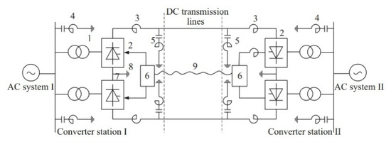
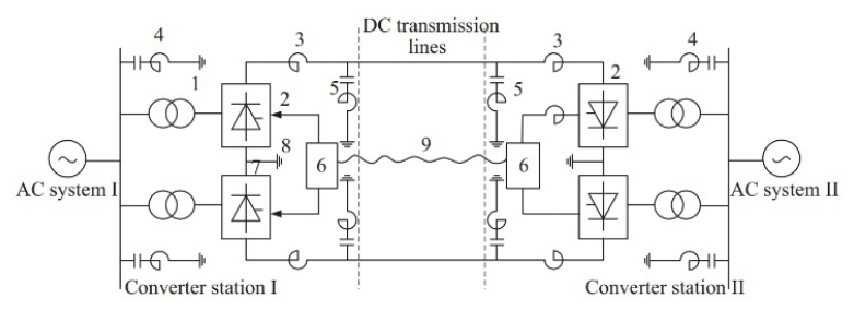
HVDC transmission networks presented in Figure 2 are uniquely positioned to facilitate the integration of IBRs into traditional AC grids due to their controllability, efficiency, and suitability for both long-distance and high-capacity transmission. Its distinct operational advantages over traditional AC transmission make it especially beneficial in several scenarios [17], including long-distance submarine cable power transmission, long-distance overhead transmission, back-to-back (BTB) HVDC systems, and renewable energy transmission. At the core of every HVDC system is the converter station, which acts as a rectifier or inverter depending on the direction of power flow.
Figure 2.
Simplified two-terminal HVDC transmission system [17].
The simplified two-terminal HVDC transmission system shown above contains converter transformers (1), power converters (2), smoothing reactors (3), AC filters (4), and DC filters (5), control and protection system (6), grounding electrode lead (7), and grounding electrode (8); telecontrol communication system (9).
2. Materials and Methods
This study implemented two simulations to assess GFM converter performance in renewable-integrated systems. The first examined a GFM-controlled BESS with solar PV, while the second analysed an MT-HVDC network for offshore wind integration. Results demonstrate that GFM converters improve grid stability, regulate voltage and frequency, and ensure compliance with IEEE interconnection standards in low-inertia systems [18].
- Solar PV Plant with BESS
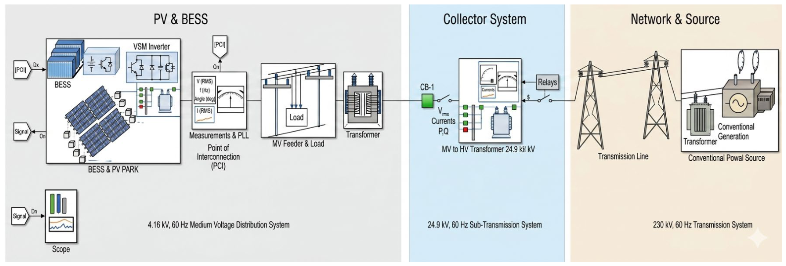
This simulation study, presented in Figure 3, evaluates the dynamic performance of a utility-scale BESS operating in conjunction with a solar PV plant. The simulated system comprises a solar PV plant and a BESS interfaced with a GFM converter. They are connected to the grid through a 4.16/24.9 kV transformer. The system was subjected to three grid disturbance scenarios:
- Scenario 1: Sudden variation in solar PV power output.
- Scenario 2: Sudden grid outage.
- Scenario 3: Temporary three-phase fault in the system.
Figure 3.
Solar PV plant with BESS.
- B.
- Offshore Wind Farm and MT-HVDC Transmission Network
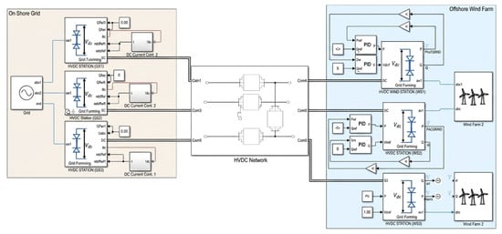
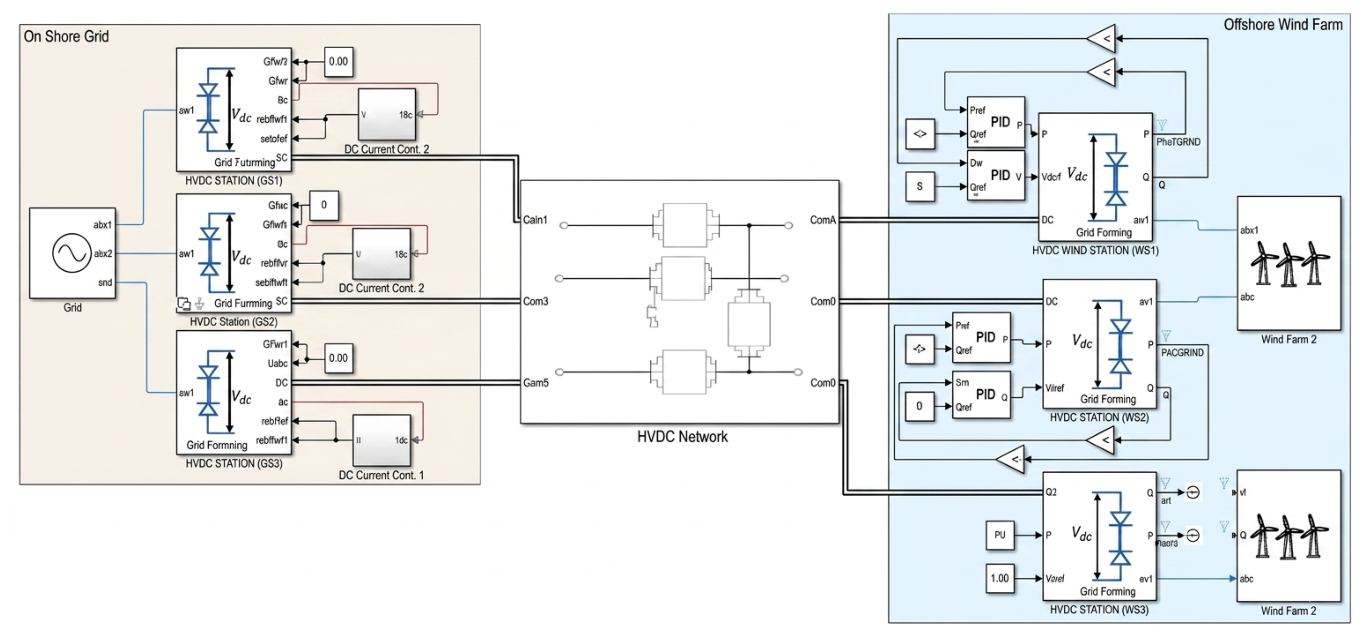
This simulation investigates the operation and dynamic performance of an MT-HVDC transmission network connecting an offshore wind farm to an onshore AC grid. The MT-HVDC network that connects the offshore wind farms and the onshore bipolar converter stations uses VSCs and ±800 kV DC submarine cables. The wind farms consist of multiple 18 MW wind turbines interfaced with back-to-back converters. For this simulation, the system was again subjected to three grid disturbance scenarios:
- Scenario 1: Sudden variation in wind power output.
- Scenario 2: Sustained power oscillation in the system.
- Scenario 3: Temporary three-phase fault on the onshore grid.
Figure 4 depicts the model for this simulation.
Figure 4.
Offshore wind farm and MT-HVDC network.
3. Results and Discussion
3.1. Solar PV Plant with BESS
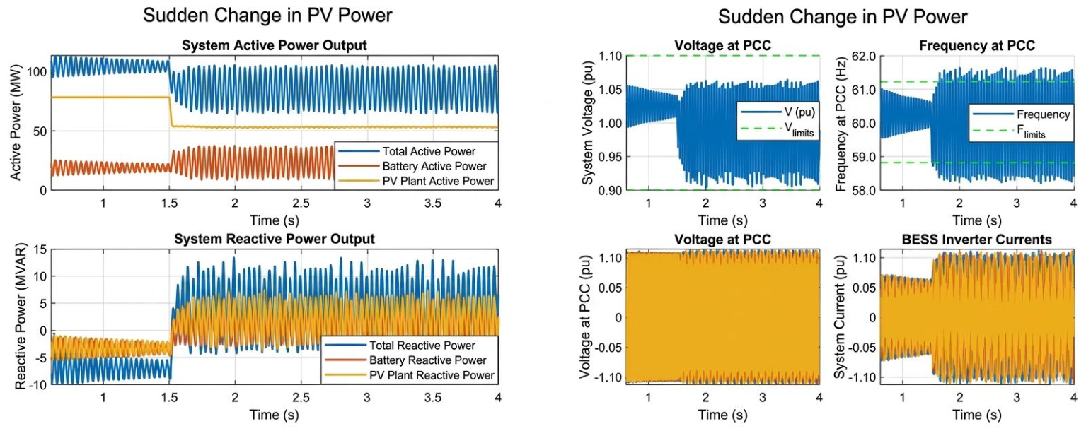
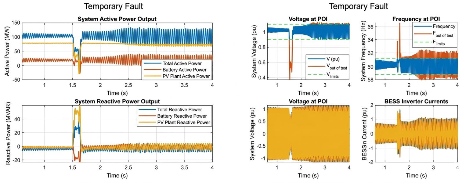
Figure 5, Figure 6, Figure 7, Figure 8, Figure 9 and Figure 10 present results under fluctuating solar PV output, the GFM BESS rapidly stabilised voltage and frequency, restoring both to near pre-disturbance levels without exceeding operational limits. In contrast, the GFL BESS showed significant oscillations, frequency deviations beyond acceptable limits, and unstable output power, whereas the GFM BESS quickly reached steady state.
- 1.
- Scenario 1–sudden variation in solar PV power output
Figure 5.
System response to change in PV power (GFM control).
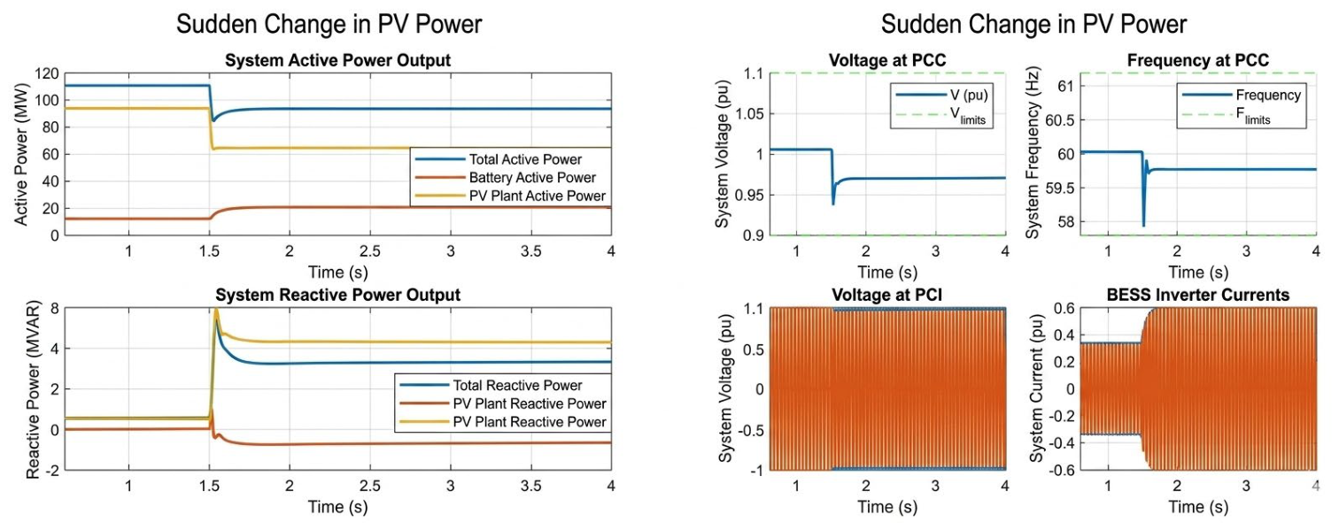
Figure 6.
System response to change in PV power (GFL control).
- 2.
- Scenario 2–sudden grid outage
Figure 7.
System response to grid outage (GFM control).
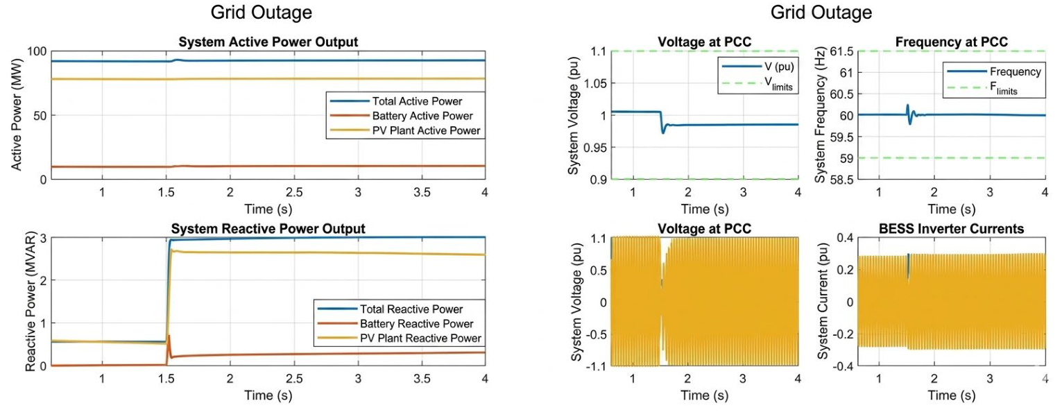
Figure 8.
System response to grid outage (GFL control).
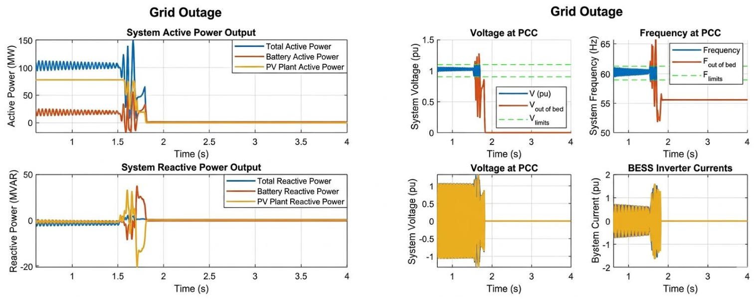
During a sudden grid outage, the GFM BESS responded immediately, restoring voltage and stabilising frequency. The GFL BESS provided no support, resulting in voltage collapse, severe current oscillations, and abnormal frequency deviations. Under a three-phase fault, both systems experienced voltage dips, but the GFM BESS recovered quickly, restoring voltage and frequency to acceptable ranges after fault clearance. The GFL BESS exhibited persistent frequency instability. Overall, across three disturbance scenarios, the GFM BESS demonstrated superior dynamic response, fast recovery, and strong grid support capabilities compared to the GFL BESS, confirming its effectiveness in maintaining stability under disturbances.
- 3.
- Scenario 3–temporary three-phase fault
Figure 9.
System response to three-phase fault (GFM control).
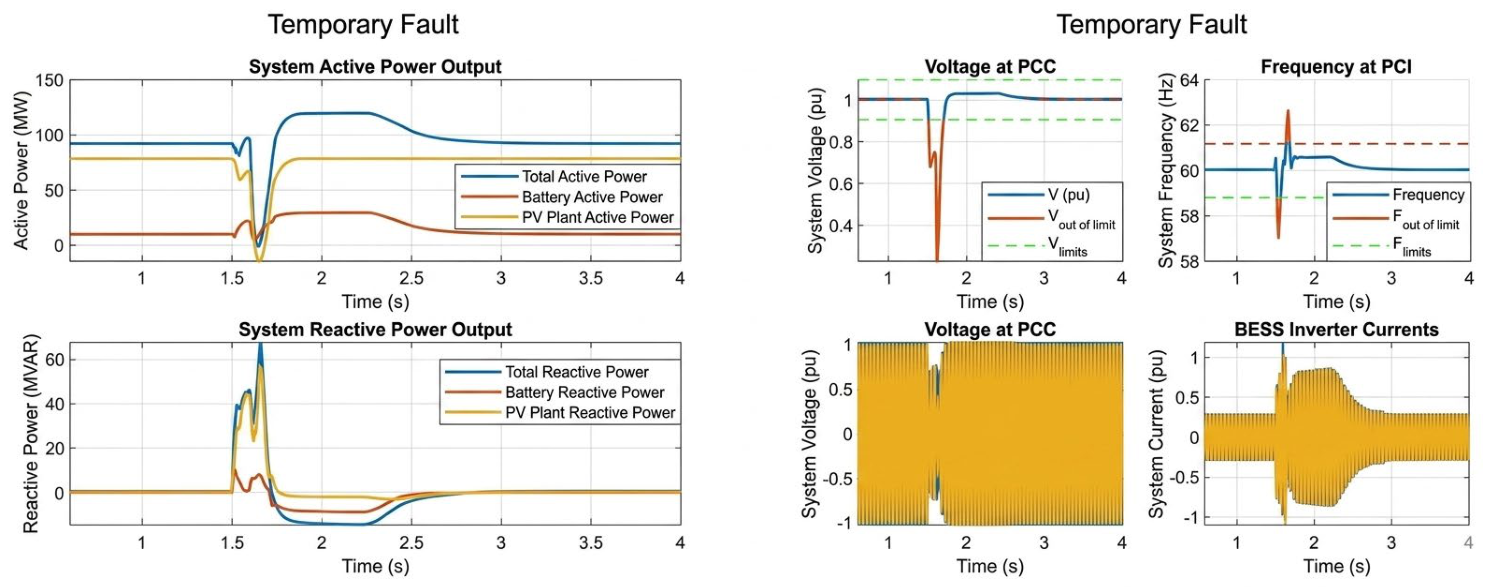
Figure 10.
System response to three-phase fault (GFL control).
3.2. Offshore Wind Farm and MT-HVDC Transmission Network
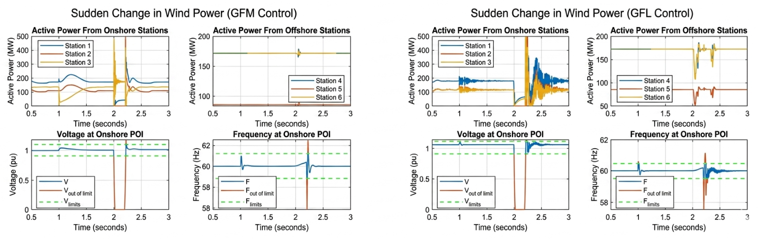
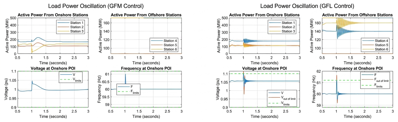
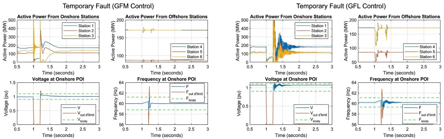
The MT-HVDC system was evaluated under disturbance conditions to compare the effectiveness of GFM and GFL control at onshore station 3. Under a sudden variation in wind power output, the GFM-controlled system displayed strong damping abilities. Onshore stations 1 to 3 experienced initial power peaks before stabilising near the 2.5-second mark. Offshore stations 4 to 6 had minimal power fluctuations, though the onshore POI at station 1 faced large voltage and frequency fluctuations momentarily before stabilising. When GFL control was used, the power curves at stations 1 to 3 were far more oscillatory and for a longer period. Stations 4 to 6 also experienced more severe power, voltage, and frequency fluctuations for a longer period than before under GFM control. Under a sustained power oscillation, stations 1 to 3 exhibited distinct rises in their power curves before quickly settling at steady state, with system voltage and frequency remaining within limits. Offshore stations 4 to 6 saw decaying oscillations in the power waveforms before returning to steady state, with voltage and frequency momentarily exceeding their limits. Although the offshore stations were mostly stable, the lingering oscillations indicated reduced system damping capability under GFL control. During the three-phase fault, GFM control ensured a relatively stable system response. Stations 1 to 3 displayed sharp power spikes before settling after the fault was cleared, though the voltage and frequency waveforms of the onshore POI expectedly exceeded their operating limits during the severe fault. The power waveforms of stations 4 to 6 remained largely stable throughout the fault. With GFL control, stations 1 to 3 again showed spikes in output power, as they did under GFM control, but now far more severe. Additionally, stations 4 to 6 displayed more severe, repeated dips in power output, suggesting a greater disturbance in the system from the fault when station 3 is operated under GFL control. The onshore POI saw voltage and frequency waveforms exceed operating limits, with sustained oscillations lasting for an extended time before steady-state operation is restored after the fault is cleared. An MT-HVDC transmission network is evaluated using GFM and GFL controllers at the onshore converter station 3, presented in Figure 11, Figure 12 and Figure 13.
- 1.
- Scenario 1–sudden variation in wind power output.
Figure 11.
System response to a change in wind power output.
- 2.
- Scenario 2–sustained power oscillation in the system
Figure 12.
System response to power oscillation.
- 3.
- Scenario 3–onshore three-phase fault
Figure 13.
System response to a three-phase fault.
4. Conclusions
This study has explored the evolving challenges of power system stability in the context of increased IBR integration and reduced synchronous generators. With limited contributions to inertia, fault current, and voltage regulation, IBRs alter the dynamic behaviour of the grid, requiring the adoption of new technologies and control strategies. However, despite the challenges involved in implementing the proposed grid-stabilising technologies into modern power systems, the findings support a clear move towards integrating GFM converters, BESSs, and VSC-HVDC transmission networks.
Author Contributions
Conceptualization by X.A. and A.A.A., methodology, X.A.; software, X.A.; validation, X.A. and A.A.A.; formal analysis, X.A.; writing—original draft preparation, X.A.; writing—review and editing, X.A. and A.A.A.; visualisation, X.A. and A.A.A.; supervision, A.A.A.; funding acquisition, A.A.A. All authors have read and agreed to the published version of the manuscript.
Funding
This research received no external funding.
Institutional Review Board Statement
Not applicable.
Informed Consent Statement
Not applicable.
Data Availability Statement
No new data were created or analyzed in this study.
Acknowledgments
The authors appreciate the Department of Electrical Power Engineering, Durban University of Technology, South Africa.
Conflicts of Interest
The authors declare no conflict of interest.
References
- Aljarrah, R.; Fawaz, B.B.; Salem, Q.; Karimi, M.; Marzooghi, H.; Azizipanah-Abarghooee, R. Issues and challenges of grid-following converters interfacing renewable energy sources in low inertia systems: A review. IEEE Access 2024, 12, 5534–5561. [Google Scholar] [CrossRef] [Scilit]
- European Network of Transmission System Operators for Electricity. HVDC Links in System Operations, ENTSOE. 2 December 2019. Available online: https://eepublicdownloads.entsoe.eu/clean-documents/SOC%20documents/20191203_HVDC%20links%20in%20system%20operations.pdf (accessed on 9 May 2025).
- Luburić, Z.; Pandžić, H.; Plavšić, T.; Teklić, L.; Valentić, V. Role of energy storage in ensuring transmission system adequacy and security. Energy 2018, 156, 229–239. [Google Scholar] [CrossRef] [Scilit]
- International Renewable Energy Agency. Renewables in 2024: 5 Key Facts Behind a Record-Breaking Year, International Renewable Energy Agency. 17 April 2025. Available online: https://www.irena.org/News/articles/2025/Apr/Renewables-in-2024-5-Key-Facts-Behind-a-Record-Breaking-Year (accessed on 9 May 2025).
- International Energy Agency. Renewables. International Energy Agency. 2024. Available online: https://www.iea.org/energy-system/renewables (accessed on 9 May 2025).
- European Commission. Renewable Energy Targets. European Commission. 2022. Available online: https://energy.ec.europa.eu/topics/renewable-energy/renewable-energy-directive-targets-and-rules/renewable-energy-targets_en (accessed on 9 May 2025).
- Environmental Protection Agency. Summary of Inflation Reduction Act Provisions Related to Renewable Energy. Environmental Protection Agency. 28 January 2025. Available online: https://www.epa.gov/green-power-markets/summary-inflation-reduction-act-provisions-related-renewable-energy#:~:text=Most%20provisions%20of%20the%20Inflation%20Reduction%20Act%20of,educational%20institutions%2C%20and%20state%2C%20local%2C%20and%20tribal%20 (accessed on 9 May 2025).
- Energyworld. Boosting Innovation: The Impact of PLI Schemes on Renewable Energy Technologies. The Economic Times. 30 January 2024. Available online: https://energy.economictimes.indiatimes.com/news/renewable/boosting-innovation-the-impact-of-pli-schemes-on-renewable-energy-technologies/107256169 (accessed on 9 January 2025).
- Saadat, H. Chapter 11-Stability. In Power System Analysis; PSA Publishing: New York, NY, USA, 2010; Volume 2, pp. 499–553. [Google Scholar]
- Wang, W.M.; Zeng, H.B.; Liang, J.M.; Xiao, S.P. Sampled-data-based load frequency control for power systems considering time delays. J. Frankl. Inst. 2025, 362, 107477. [Google Scholar] [CrossRef] [Scilit]
- Furlaneto, R.M.; Kocar, I.; Grilo-Pavani, A.; Karaagac, U.L.A.Ş.; Haddadi, A.; Farantatos, E. Short circuit network equivalents of systems with inverter-based resources. Electr. Power Syst. Res. 2021, 199, 107314. [Google Scholar] [CrossRef] [Scilit]
- Rosso, R.; Wang, X.; Liserre, M.; Lu, X.; Engelken, S. Grid-forming converters: Control approaches, grid-synchronization, and future trends—A review. IEEE Open J. Ind. Appl. 2021, 2, 93–109. [Google Scholar] [CrossRef] [Scilit]
- Stecca, M.; Elizondo, L.R.; Soeiro, T.B.; Bauer, P.; Palensky, P. A comprehensive review of the integration of battery energy storage systems into distribution networks. IEEE Open J. Ind. Electron. Soc. 2020, 1, 46–65. [Google Scholar] [CrossRef] [Scilit]
- Progressture Solar. An Overview of Battery Energy Storage Systems (BESS): How It Works, Its Benefits, and Applications, Progressture Solar. 16 December 2022. Available online: https://www.progressturesolar.com/post/an-overview-of-battery-energy-storage-systems-bess-how-it-works-its-benefits-and-applications (accessed on 16 June 2025).
- Mviri, F.S.M. Battery storage systems in electric power grid: A review. J. Phys. Conf. Ser. 2022, 2276, 012016. [Google Scholar]
- Rana, M.M.; Uddin, M.; Sarkar, M.R.; Meraj, S.T.; Shafiullah, G.M.; Muyeen, S.M.; Islam, M.A.; Jamal, T. Applications of energy storage systems in power grids with and without renewable energy integration—A comprehensive review. J. Energy Storage 2023, 68, 107811. [Google Scholar] [CrossRef] [Scilit]
- Han, M.; Gole, M.A. Chapter 1: HVDC and the needs for modeling and simulation. In Modeling and Simulation of HVDC Transmission; The Institution of Engineering and Technology: London, UK, 2020; pp. 1–25. [Google Scholar]
- IEEE 2800-2022; IEEE Standard for Interconnection and Interoperability of Inverter-Based Resources (IBRs) Interconnecting with Associated Transmission Electric Power Systems. IEEE Standards Association: Piscataway, NJ, USA, 2020. Available online: https://standards.ieee.org/ieee/2800/10453/ (accessed on 12 June 2025).
Disclaimer/Publisher’s Note: The statements, opinions and data contained in all publications are solely those of the individual author(s) and contributor(s) and not of MDPI and/or the editor(s). MDPI and/or the editor(s) disclaim responsibility for any injury to people or property resulting from any ideas, methods, instructions or products referred to in the content. |
© 2026 by the authors. Licensee MDPI, Basel, Switzerland. This article is an open access article distributed under the terms and conditions of the Creative Commons Attribution (CC BY) license.