1. Introduction
The development of the DC microgrid has increased rapidly due to renewable energy penetration and distributed storage requirement. Unlike AC systems, DC architecture eliminates synchronization complexity and reduces conversion losses. However, maintaining DC-link voltage stability is very challenging when wind generation fluctuates suddenly and loads change dynamically.
The traditional PI controller is widely used in industrial applications because it is simple and easy to implement. But the PI controller has a fixed gain structure and cannot adapt to the nonlinear behavior of the wind and battery system. When wind speed changes rapidly, PI often produces overshoot and a longer settling time.
To overcome this issue, intelligent controllers such as ANFIS are adopted. ANFIS combines neural learning capability and fuzzy inference reasoning, which allow adaptive and nonlinear mapping. This work compares PI and ANFIS in a detailed manner under two disturbance scenarios.
The contribution of this study includes:
Mathematical modeling of wind–battery DC microgrid.
Design of ANFIS controller using expert EMS data.
Quantitative comparison using RMSE, IAE and battery throughput.
The integration of hybrid renewable energy systems (HRESs) with battery energy storage in DC microgrids has been widely investigated in recent years to improve reliability, stability and optimal power sharing. Recent conference research confirms that intelligent fuzzy-based control methods provide effective dynamic regulation for renewable energy systems subjected to environmental uncertainty [
1,
2,
3]. Different control strategies, forecasting techniques and optimization algorithms have been proposed in order to handle the intermittency of wind and photovoltaic sources.
An intelligent prediction-based energy management strategy for a PV–wind–battery microgrid is discussed in [
4]. The proposed control is based on the generation of reference source currents and optimal management of power flux using artificial intelligence. A long short-term memory (LSTM) network is adopted to forecast energy production and battery state of charge. The study shows that predictive control improves supply–demand balance and ensures continuous load supply under variable weather condition. However, the complexity of the forecasting algorithm increases the computational burden.
An optimized autonomous DC microgrid integrating PV/wind/battery/diesel sources is presented in [
5], where hybrid PSO-GA combined with active disturbance rejection control (ADRC) is used. The controller regulates AC bus voltage and frequency, while an extended state observer compensates for disturbances and modeling errors. The results indicate improved power quality and stable operation, but the hybrid optimization approach requires tuning effort and increase control structure complexity.
Standalone hybrid PV–wind microgrid modeling and fuzzy-based MPPT control is explained in [
6]. The controller manages battery charging and discharging according to SOC limits (20–80%) and protects the system against overcharging and deep discharge. The fuzzy MPPT enhances power extraction from the PV system. Although effective, the system mainly focusses on rule-based SOC protection rather than adaptive energy prediction.
Hybrid PV/wind/battery/fuel cell systems with advanced energy management are analyzed in [
7]. A combined direct reactive power control and fuzzy logic algorithm is proposed for waveform improvement. The work also includes hydrogen production and hybrid battery–supercapacitor storage. The management algorithm ensures smooth power output and service continuity, but the architecture become relatively complex due to multiple storage layers.
Optimal sizing of a hybrid solar/wind/battery/biogasifier/diesel microgrid is studied in [
8] using hybrid grey wolf and cuckoo search optimization. The objective is to minimize the annual cost and levelized cost of energy (LCOE). The optimized system achieved improved economic performance compared to PSO and GA. This study highlights the importance of component sizing in energy management, even though dynamic control aspects are less emphasized.
Energy management and voltage control using ANN, PID and fuzzy controllers is investigated in [
9]. The comparison results show that intelligent controllers outperform conventional PID in voltage stability and frequency regulation. The work confirms that adaptive controllers provide better microgrid stability but does not deeply analyze battery-side power dynamics under rapid variations.
A robust sliding mode control strategy for a hybrid solar/wind/battery system is proposed in [
10]. Lyapunov stability analysis ensures asymptotic convergence and robustness against disturbances. The approach stabilizes DC-bus and load voltages under varying irradiance and wind speed. Although robustness is improved, sliding mode control may introduce a chattering effect if not properly designed.
Voltage regulation in an islanded DC microgrid using an African vulture optimization-tuned PI controller is discussed in [
11]. The cascade double-loop structure improves DC-bus stability compared with PSO-based tuning. The results show better overshoot suppression and dynamic response, but it still relies on a PI framework.
Battery energy storage sizing considering wind penetration is analyzed in [
12] using modified biogeography optimization. The study emphasizes economic operation and battery lifespan extension. It proves that optimal depth of discharge and capacity selection significantly affect microgrid performance. However, the focus remains on the planning stage rather than real-time control.
Implementation of a fuzzy PID controller with SMES support in a standalone wind/battery system is presented in [
13]. The fuzzy PID improves overshoot by around 24% compared to conventional PID. Hardware-in-the-loop validation confirms improved transient stability. The inclusion of SMES enhances transient support, though cost and system complexity increase.
Hybrid renewable system control with wind, PV and battery using multi-converter topology is detailed in [
14]. MPPT algorithms are implemented for both wind and PV, while direct power control regulates a grid-side converter. Energy management strategies are developed for different wind and load conditions. The study demonstrates the practical importance of coordinated converter control.
Power management control of an autonomous PV/wind/battery system with a hybrid MPPT approach is described in [
15]. The integration of hybrid MPPT and power flow management reduces battery stress and improves efficiency. Simulation results under different weather profiles confirm improved energy balancing capability. An ANFIS-based intelligent control strategy for small-scale wind turbines supplying a regulated 48 V DC load has been investigated for rural electrification applications [
1]. The system, modeled with real wind data and IEC turbulence conditions, demonstrates improved settling time and reduced voltage ripple compared to conventional PI control. The study confirms the technical feasibility of ANFIS for decentralized DC wind systems, while indicating the need for further economic and experimental validation.
From the previously discussed studies, it can be observed that most of the research works concentrate on optimal sizing, forecasting-based energy management and advanced intelligent control strategies for hybrid renewable microgrids. Although various controllers such as fuzzy logic, neural networks and robust control techniques have been applied to enhance stability, detailed comparative investigation between conventional PI and adaptive intelligent controllers for DC-bus voltage regulation is still limited. In many cases, voltage stability is treated as a supporting objective rather than the main focus [
16], and transient characteristics [
17] like overshoot, undershoot and settling behavior under rapid wind and load changes are not deeply analyzed. Therefore, there remains a research gap in systematically evaluating the comparative dynamic performance of ANFIS and PI control strategies for voltage regulation in wind–battery DC microgrids, which motivates the present work.
The present study extends existing work by providing a focused comparative investigation of PI and ANFIS control strategies specifically for DC-link voltage regulation in a wind–battery DC microgrid under identical disturbance conditions. Unlike previous studies that primarily address general intelligent control or hybrid energy management, this work emphasizes detailed transient performance evaluation, including overshoot, undershoot, settling time, battery power response, and voltage stabilization under wind and load disturbances. Thus, the contribution of this study lies in establishing a clearer dynamic-performance benchmark between conventional and adaptive intelligent control for small-scale wind–battery DC microgrids.
3. Control Strategy Development
The primary control objective is to maintain the DC-link voltage at the constant reference value . This is achieved by regulating the battery power command through an appropriate control strategy. Because wind power and load demand are continuously varying, the controller must react fast and also remain stable under nonlinear conditions.
3.1. PI Controller
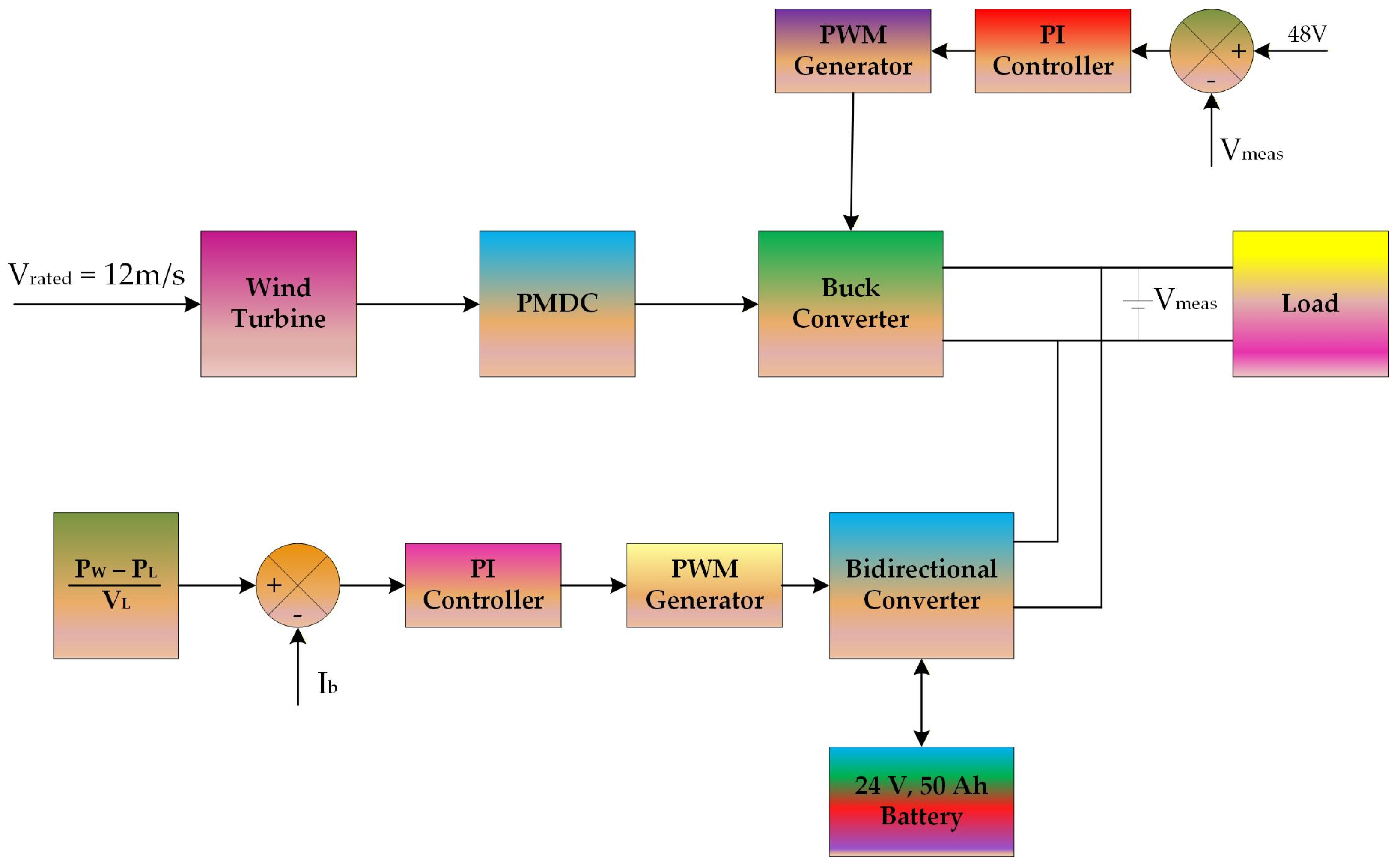
Figure 1 illustrates the block diagram of a PI-controlled wind–battery DC microgrid system designed for voltage regulation and power balance. The system consists of a wind turbine operating at a rated wind speed of 12 m/s, which drives a Permanent Magnet DC (PMDC) generator. The generated DC output is supplied to a buck converter that regulates the DC bus voltage.
The upper control loop in
Figure 1 represents the DC-link voltage regulation loop. The measured DC bus voltage (V
meas) is compared with the reference voltage of 48 V. The error signal is processed through a PI controller, and the controller output is fed to a PWM generator. The generated PWM pulses control the switching of the buck converter to maintain the DC-link voltage at the desired reference level.
The lower control loop manages battery power flow. The difference between wind power (PW) and load power (PL), divided by load voltage (VL), generates the reference battery current. This reference is compared with the measured battery current (Ib), and the error is passed through another PI controller. The corresponding PWM generator produces gating signals for the bidirectional converter connected to the 24 V, 50 Ah battery.
When wind generation exceeds load demand, the bidirectional converter operates in charging mode to store excess energy in the battery. Conversely, during wind deficit conditions, the battery discharges to support the load and maintain DC bus stability. Thus, as shown in
Figure 1, the coordinated action of voltage regulation loop and battery current control loop ensures stable operation of the wind–battery DC microgrid system.
The proportional–integral (PI) controller is selected as the baseline method for comparison. It operates by processing the instantaneous voltage error defined as:
To improve dynamic performance, a feed-forward compensation term proportional to the power mismatch is included. In addition, an anti-windup clamping mechanism (intClamp) is implemented to prevent integrator saturation during large transient conditions.
The battery power command is therefore expressed as:
where
and
represent proportional and integral gains respectively. The feed-forward term
provides partial compensation for power imbalance before significant voltage deviation occurs.
The controller gains were tuned empirically to ensure closed-loop stability across the operating range, resulting in and . Although this tuning gives an acceptable steady-state response, the linear nature of the PI controller limits its adaptability under high nonlinear wind fluctuations and sudden load steps.
3.2. ANFIS Controller
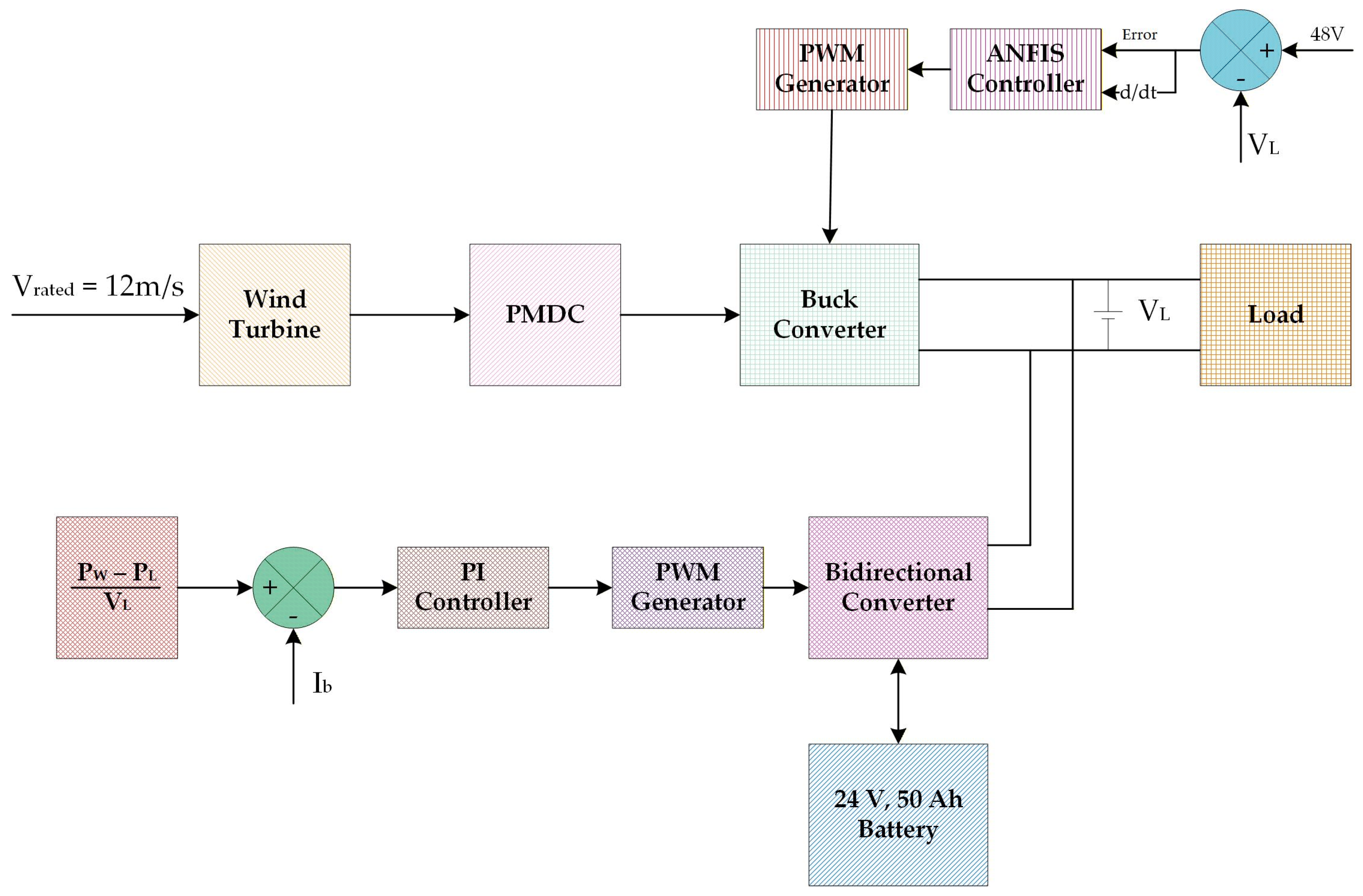
Figure 2 illustrates the block diagram of the proposed ANFIS-controlled wind–battery DC microgrid system for enhanced voltage regulation and power management. Similar to the previous configuration, the wind turbine operating at a rated wind speed of 12 m/s drives a PMDC generator. The generated DC power is supplied to a buck converter which feeds the DC bus and load.
In
Figure 2, the upper control loop is responsible for DC-link voltage regulation using an ANFIS controller instead of a conventional PI controller. The measured load voltage (V_L) is compared with the 48 V reference, and the error along with its rate of change (d/dt) are provided as inputs to the ANFIS controller. Based on the trained neuro-fuzzy inference system, an optimized control signal is generated and passed to the PWM generator. The PWM pulses regulate the switching of the buck converter to maintain the DC bus voltage at the desired reference value with an improved dynamic response.
The lower control loop manages the battery current through a bidirectional converter. The reference battery current is derived from the power balance equation . This reference is compared with the measured battery current (Ib), and the error is processed by a PI controller. The corresponding PWM generator produces gating pulses for the bidirectional converter connected to the 24 V, 50 Ah battery.
When wind power exceeds load demand, the battery operates in charging mode. During wind deficit conditions, the battery discharges to support the load and maintain voltage stability. As shown in
Figure 2, the integration of ANFIS in the voltage control loop enhances transient performance, reduces overshoot, and improves robustness compared to conventional control strategies.
The ANFIS controller is designed as a multi-input single-output (MISO) nonlinear regulator for DC-link voltage stabilization. It utilizes four input variables, namely voltage error , rate of change in DC voltage , battery state of charge (SoC), and instantaneous power mismatch . The output of the controller is commanded battery power .
The training of the ANFIS model was carried out for 40 epochs using approximately 4000 input–output data samples. These samples are generated from a predefined expert Energy Management System (EMS) nonlinear control law. The objective of using an expert dataset is to allow ANFIS to internalize stabilization behavior rather than relying only on error correction like a PI controller.
The expert control law is mathematically defined as:
where
ensures complete feed-forward compensation of power imbalance. The hyperbolic tangent (tanh) functions are used to introduce smooth saturation characteristics, preventing excessive battery power command during large transient conditions. The normalized error terms
and
represent scaled voltage error and its derivative, respectively.
The fuzzy inference system consists of 16 rules constructed using generalized bell-shaped membership functions (gbellmf). These membership functions allow smooth transition between operating regions. Because of this rule base, ANFIS is able to adapt control aggressiveness depending on SoC level. For example, when the SoC falls below 30%, the controller automatically reduces the discharge command to avoid deep cycling of the battery.
Unlike the conventional PI controller, which reacts only after voltage deviation occurs, ANFIS anticipates disturbances through input. This proactive compensation improves dynamic response and reduces DC-link voltage oscillations. The nonlinear mapping capability of ANFIS makes it more suitable for a wind–battery microgrid where system dynamics are strongly coupled and time-varying.
This study compares a conventional PI-based baseline controller with an advanced ANFIS-based adaptive controller. Owing to the nonlinear mapping capability and richer system information utilized by ANFIS, the objective is to evaluate the practical performance improvement over a conventional control benchmark rather than to compare structurally identical regulators.
5. Results and Discussion
The Results and Discussion Section presents a detailed analysis of the proposed wind–battery DC microgrid under different operating disturbances such as wind variation and load variation. In this section, the dynamic behavior of power sharing, battery power response, and DC-link voltage regulation is examined for both the conventional PI controller and the proposed ANFIS controller. The objective is to evaluate how effectively each controller maintains the power balance and voltage stability when sudden changes occur in generation or demand. The simulation waveforms are analyzed in the time domain to understand the transient overshoot, undershoot, settling time and steady state tracking performance. Through this comparative study, the robustness and adaptive capability of the ANFIS controller can be clearly observed against the fixed-gain PI strategy.
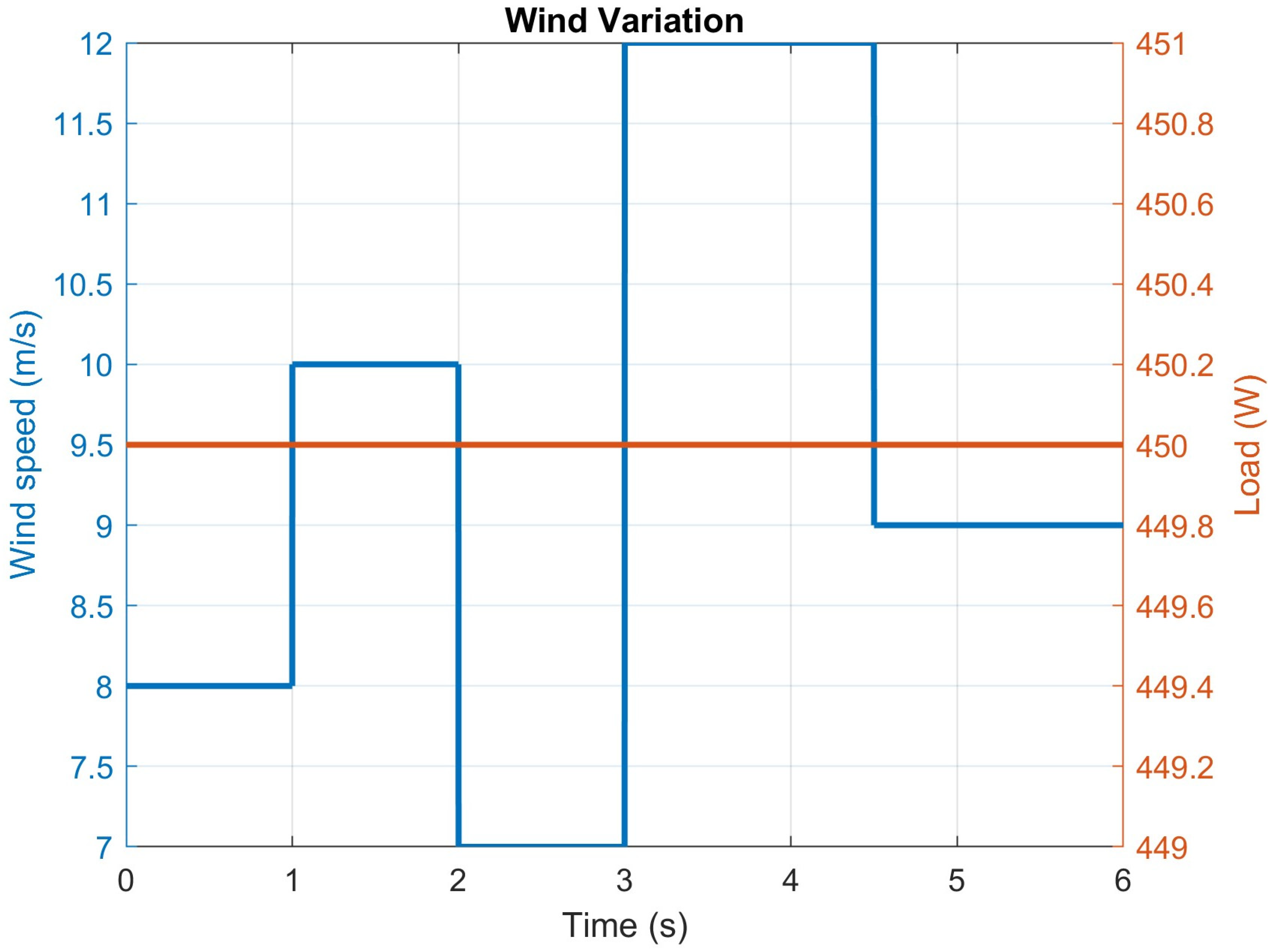
Figure 3 shows the wind speed profile and constant load condition used for testing the controller performance. The wind speed is varied stepwise from 8 m/s to 10 m/s at 1 s, then reduced to 7 m/s at 2 s, increased sharply to 12 m/s at 3 s and finally reduced to 9 m/s at 4.5 s. During this complete interval, the load is maintained as constant at 450 W. This variation creates a generation mismatch condition which is essential to evaluate the dynamic behavior of battery and DC-link control. The sudden change at 3 s represents the worst-case condition where high surplus energy is available.
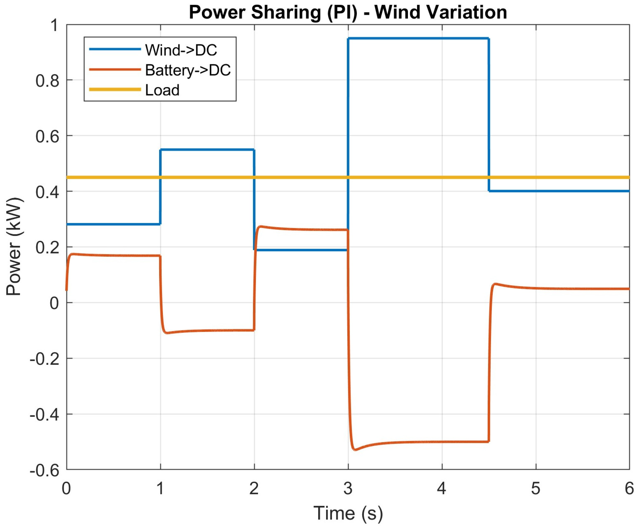
Figure 4 presents the power sharing performance using the PI controller during wind variation. It can be seen that wind power follows the wind profile and varies proportionally. When wind is low (7 m/s), the battery operates in discharge mode to support the constant load of 0.45 kW. When the wind increases to 12 m/s, the battery goes into charging mode and absorbs excess energy. However, during each transition instant, oscillatory behavior is observed in battery power. Especially at 3 s, a large negative spike (around –0.55 kW) is observed which indicates the poor damping characteristics of the PI controller.
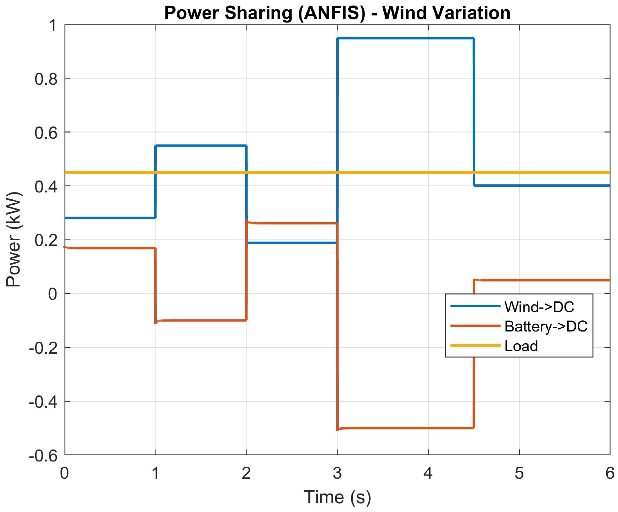
Figure 5 shows the power sharing using the ANFIS controller under the same wind profile. The wind-to-DC power closely follows the variation, and the battery compensates for the mismatch smoothly. Compared to PI, the battery power transition is smoother and settling is faster. The negative charging region at high wind is controlled without large oscillation. It shows that the ANFIS adaptive mechanism improves the stability of the power balance.
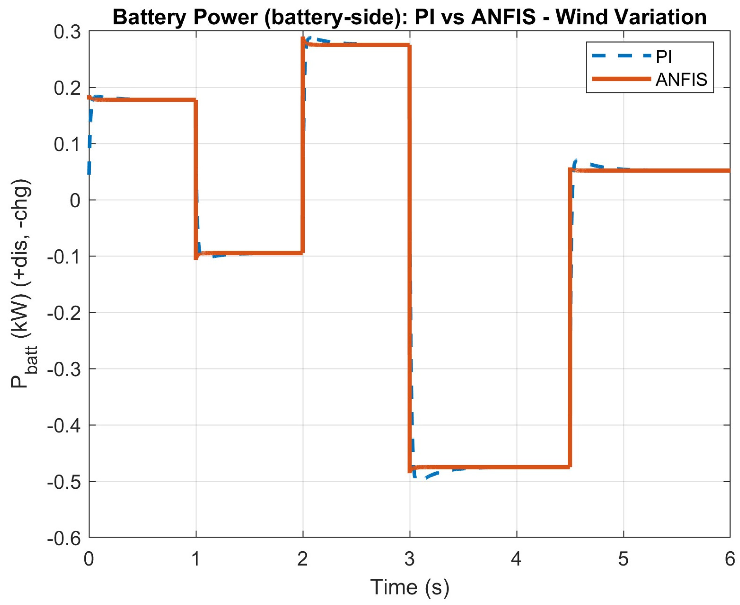
Figure 6 compares directly the battery-side power for PI and ANFIS under wind variation. The PI controller shows an overshoot and undershoots during each step change. At 3 s, the PI response drops nearly –0.5 kW before settling. In contrast, the ANFIS response is almost critically damped and the transient ripple is very small. The steady state tracking is nearly identical but the dynamic response of ANFIS is clearly better.
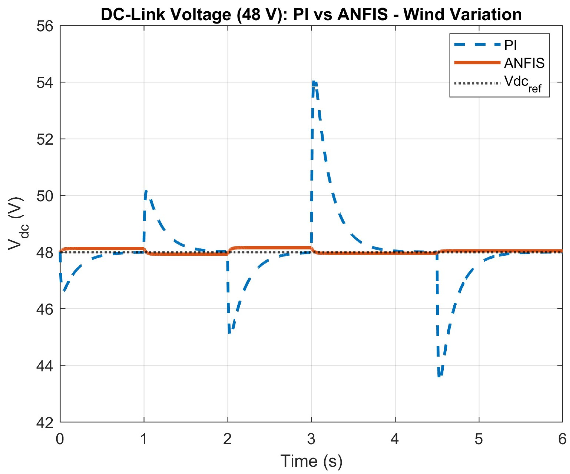
Figure 7 illustrates the DC-link voltage regulation performance. The reference voltage is fixed at 48 V. The PI controller shows a significant overshoot (around 54 V) at 3 s and undershoot (around 45 V) at 2 s and 4.5 s. These deviations can stress converter components. On the other hand, ANFIS maintains DC-link voltage very close to 48 V with negligible deviation (<0.2 V). The voltage ripple is highly suppressed. This proves that ANFIS gives superior voltage regulation under intermittent wind conditions.
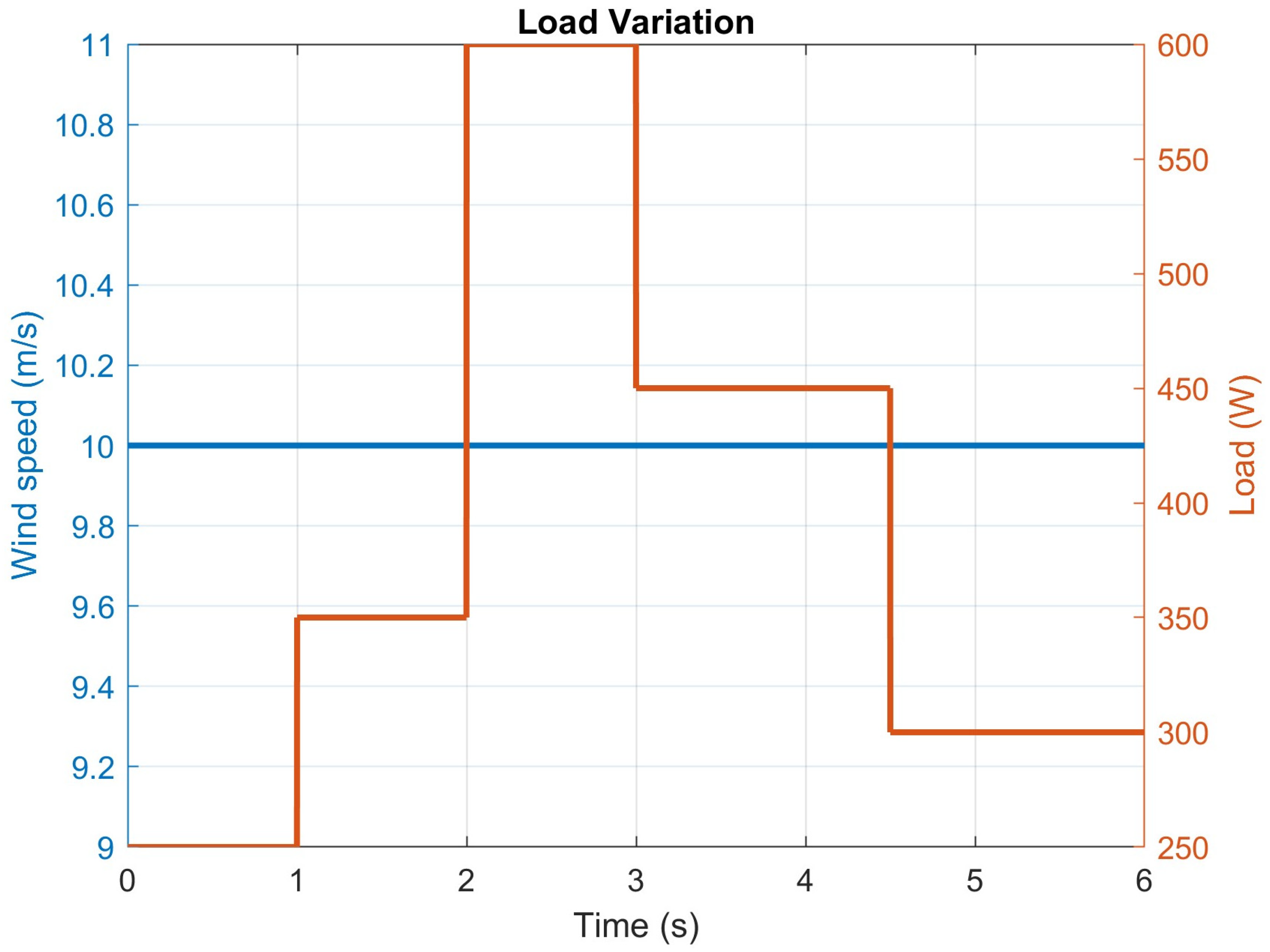
Figure 8 shows the load variation profile while wind speed is kept constant at 10 m/s. The load increases from 250 W to 350 W at 1 s, then to 600 W at 2 s, and reduces to 450 W at 3 s and finally 300 W at 4.5 s. This creates sudden demand fluctuation and tests the dynamic capability of battery control.
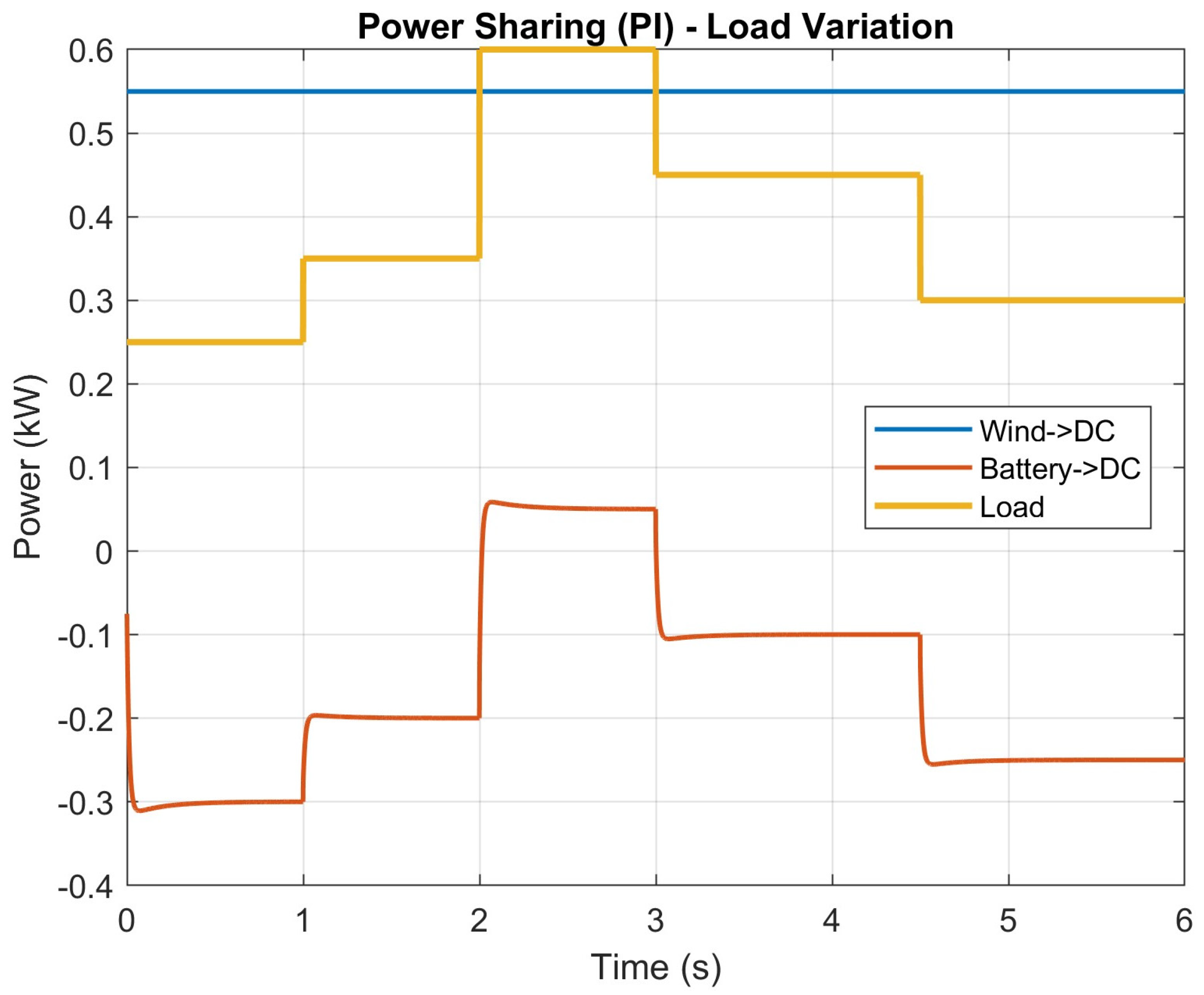
Figure 9 shows power sharing under PI control during load variation. Since wind power is constant (~0.55 kW), the battery must adjust to meet changing load demand. At 2 s when load increases to 600 W, the battery shifts from charging to discharging mode. However, transient oscillation is visible at each switching instant. The PI controller produces spike behavior before reaching steady state which indicates slower dynamic adaptation.
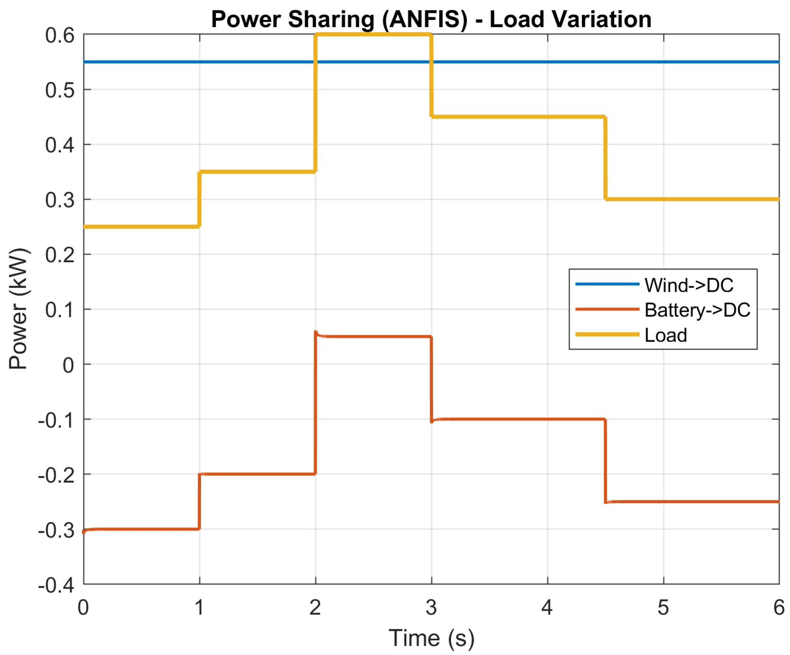
Figure 10 shows the same condition using the ANFIS controller. The battery smoothly transitions between charging and discharging without noticeable oscillation. The settling time is shorter and steady state error is minimal. The adaptive rule-based control helps to minimize dynamic stress in the battery.
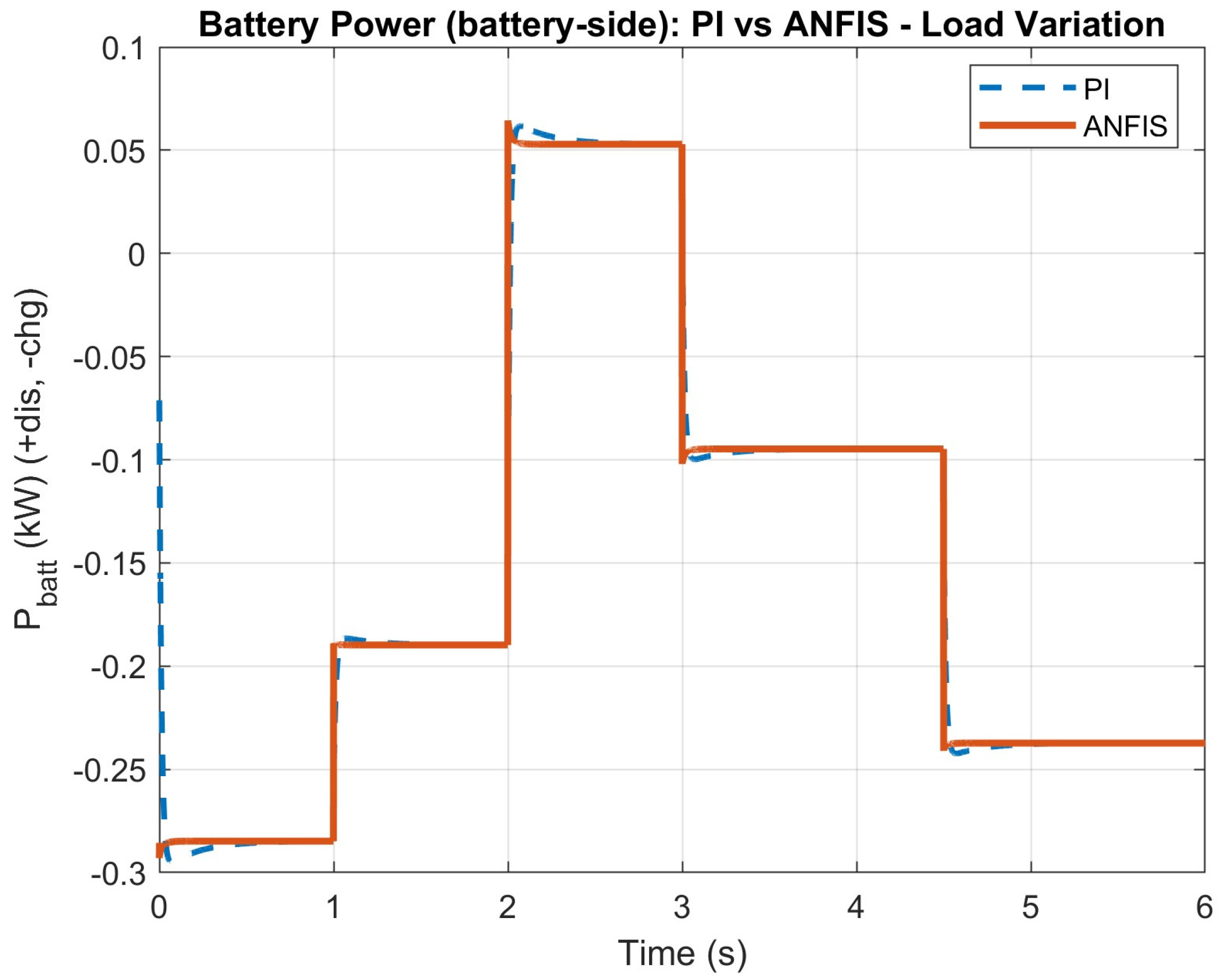
Figure 11 compares the battery power directly. The PI response shows a small oscillation and a slight overshoot at 2 s and 3 s. The ANFIS curve is smoother and follows the desired power instantly. The difference is not extremely large in steady state but the transient quality of ANFIS is clearly improved.
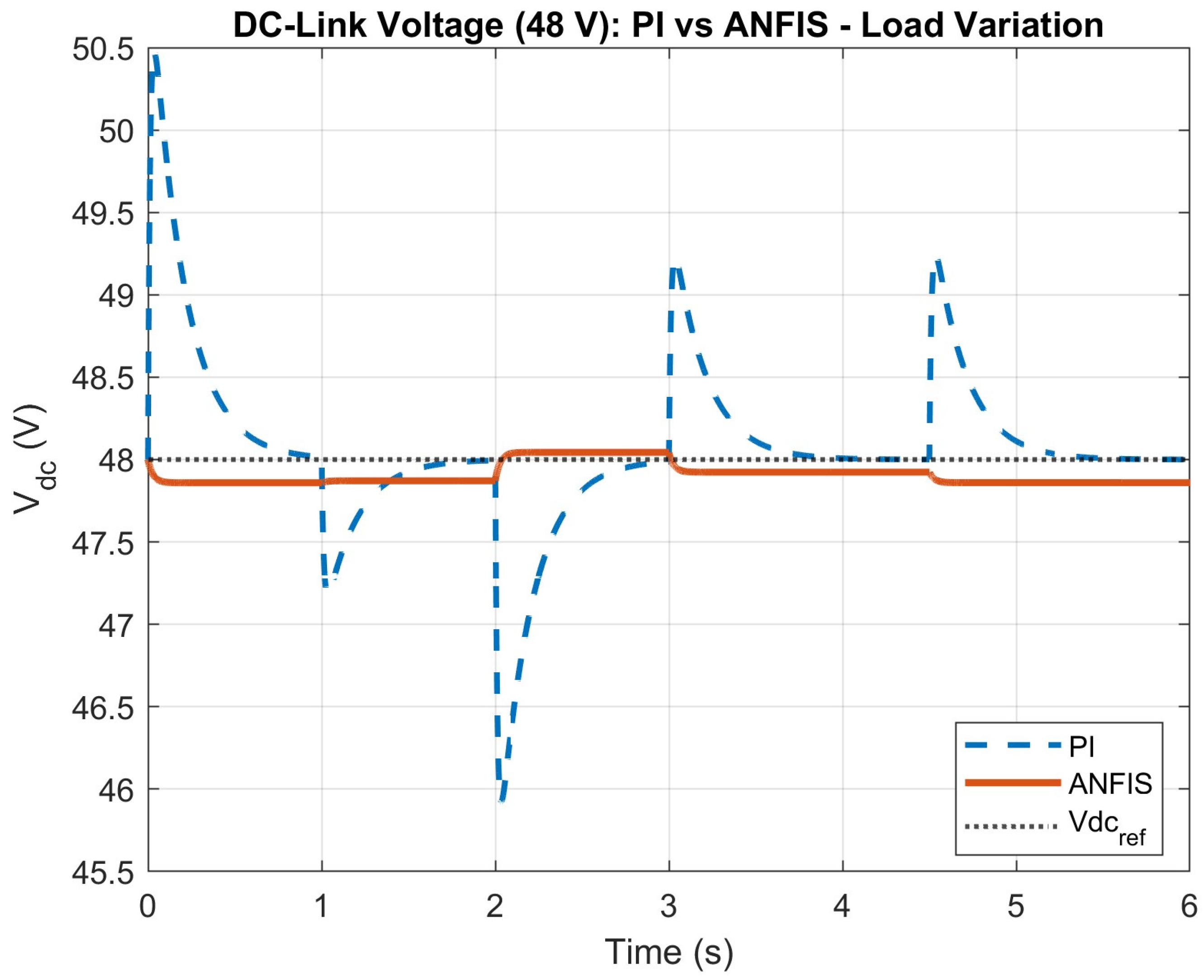
Figure 12 presents DC-link voltage performance during load changes. The PI controller shows an overshoot of up to 50.5 V and an undershoot of nearly 46 V. These fluctuations occur at every load step. In contrast, ANFIS keeps DC voltage almost constant at 48 V with a very small ripple. This indicates strong robustness against load disturbance.
The voltage tracking error is defined as the instantaneous deviation between the reference DC-link voltage and the measured DC-link voltage. Based on the simulation results, the PI controller exhibits larger transient deviation and slower recovery, whereas the ANFIS controller maintains a lower tracking error and faster settling under both wind and load disturbances. Accordingly, the reported performance improvement is based on the observed reduction in voltage deviation and enhancement in transient response quality. The comparative performance of the PI and ANFIS controllers under wind and load disturbance conditions is summarized in
Table 2.
From the above results, it can be observed that PI controller is capable of maintaining power balance but it shows large transient deviation under sudden disturbance. The overshoot and undershoot in DC-link voltage is comparatively high, especially during wind variation. This may reduce the reliability of the converter and battery system.
The ANFIS controller shows an improved damping characteristic, fast settling, and minimal ripple. The adaptive nature allows it to respond effectively to nonlinear wind energy and sudden load fluctuation. Therefore, it can be concluded that ANFIS-based energy management provides superior dynamic performance and enhanced DC-link stability compared to a conventional PI controller for a hybrid wind–battery DC microgrid system.