


Abstract
The article reviews the methods of determining the angular position of a pilot’s helmet used on board modern aircraft, and analyzes the methods of determining the angular position of an object used in aviation spatial orientation and inertial navigation systems. A functional analysis of the NSC-1 Orion helmet-mounted targeting system developed at AFIT was performed. The main part of the work consists of the development of new, original mathematical models for determining the angular position of the pilot’s helmet using quaternions, simulation studies of these models, and experimental verification of their results. The stages necessary for the development of mathematical models and their proper testing for disturbances occurring in the measurement of gravitational acceleration (sensor errors and acceleration from maneuvers) and the magnetic field (sensor errors and the influence of the aircraft’s own magnetic field) are presented.
1. Introduction
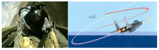
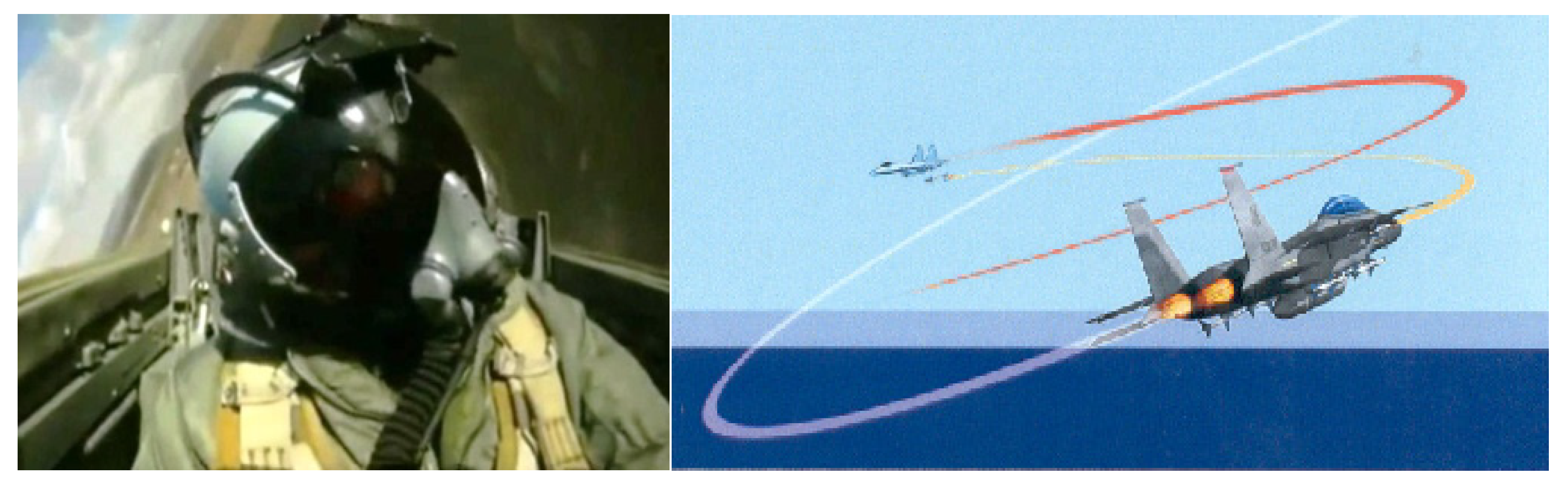
Modern aircraft with advanced digital avionics are increasingly equipped with helmet-mounted display systems and onboard weapon control systems. The use of such systems increases the situational and tactical awareness of multi-role aircraft pilots, which translates into greater combat mission effectiveness. A very important aspect of the use of helmet-mounted targeting and flight parameter display systems is the increase in flight reliability and safety. Considering the widespread use of HMDs and modern methods of determining the position of the pilot’s helmet, as well as the miniaturization of the electronic components used, the helmet-mounted system has become a very important tool supporting the pilot during air combat (Figure 1) and attacking ground targets. Modern helmet-mounted targeting systems consist of two main components: a system for displaying piloting, navigation, and targeting parameters, and a system for determining the angular position of the pilot’s helmet, designed for helmet-mounted control of onboard weapons. The main research problem in the context of helmet-mounted systems is the methods of tracking and determining the angular position of the helmet so that the displayed image precisely follows the pilot’s head movements without delay [1,2].
Figure 1.
Schematic diagram illustrating how to gain air superiority by using a modern helmet-mounted targeting system [1].
For this purpose, special positioning systems have been developed that are installed in the aircraft cockpit and on the pilot’s helmet, allowing the position of the pilot’s helmet to be determined in a coordinate system related to the aircraft. One way to reduce their inaccuracy is to use quaternions to determine the angular position of the aircraft and the pilot’s helmet. Examples of such analyses are the works, concerning the determination of the angular position of an aircraft relative to the horizontal coordinate system adopted in air navigation. This work presents an innovative, deterministic solution to Whab’s problem, which involves determining the orientation of an object in quaternion form, taking into account changes in two pairs of vectors obtained from inertial sensors.
This approach has enabled the development of new methods for determining the position of the pilot’s helmet relative to the aircraft cabin, free from ambiguities and problems with singularities that occur when using the Euler angle method [3].
2. Methods for Determining the Angular Position of a Pilot’s Helmet
An analysis of available literature and online publications [4,5,6,7,8,9,10,11,12] shows that the construction of a modern helmet-mounted targeting system is a complex issue due to its technological sophistication, requiring the use of sophisticated devices, computational methods, and data processing. One of the main research issues is the problem of achieving the required accuracy in determining the angular position of the helmet, which is necessary for helmet-mounted control of aircraft weapons.
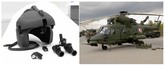
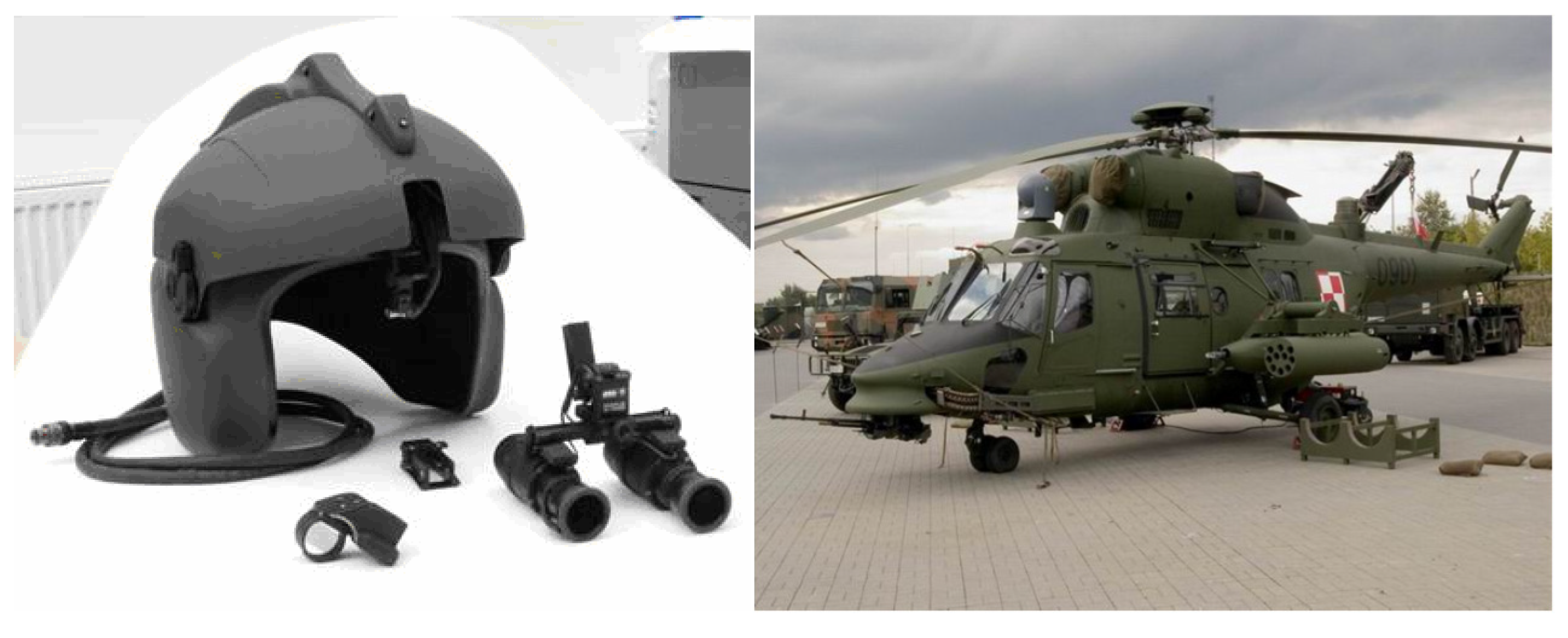
The latest targeting systems for determining the spatial position of a pilot’s helmet use optoelectronic sensors with an additional eye tracking system, as well as increasingly accurate magnetic and inertial sensors, often in a hybrid application combining different types of sensors within a single helmet-mounted system. Similar analytical work was carried out at the Air Force Institute of Technology (AFIT). As a result of this work, a technology demonstrator was developed and built, which performs the functions of an on-helmet targeting system by controlling the operation of on-board combat equipment and cooperating with the Toplite optoelectronic head, which was installed and integrated on board the W-3PL Głuszec military helicopter. It consists of the NSC-1 Orion helmet-mounted targeting system and elements of the ZSA integrated avionics system (Figure 2).
Figure 2.
View of the technology demonstrator for the helmet-mounted weapon control system of the W-3PL Głuszec helicopter with the NSC-1 Orion system [5].
The basic method implemented in the NSC-1 Orion system is the electro-optical method, based on the analysis of light spot coordinates in the image obtained from a camera mounted above the pilot’s helmet, as well as on the use of artificial neural networks. The accuracy of azimuth and elevation determination is ±2°. An alternative method, tested in laboratory conditions, is a method using quaternion calculus [5].
2.1. Quaternion Method Developed for Helmet-Mounted Cueing Systems
The effective quaternion method developed at AFIT uses a quaternion describing the angular position of the pilot’s helmet based on measured linear accelerations in the aircraft coordinate system and in the pilot’s helmet coordinate system. The task of the quaternion method is to determine, based on the measured linear accelerations of the helmet and the aircraft, the current value of the quaternion of the angular position of the pilot’s helmet relative to the aircraft cabin, and then to determine the angles of elevation and azimuth of the pilot’s helmet based on generally known mathematical relationships linking the components of the quaternion with Euler angles (pitch, roll, and yaw).
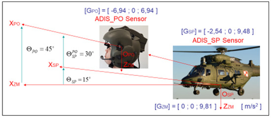
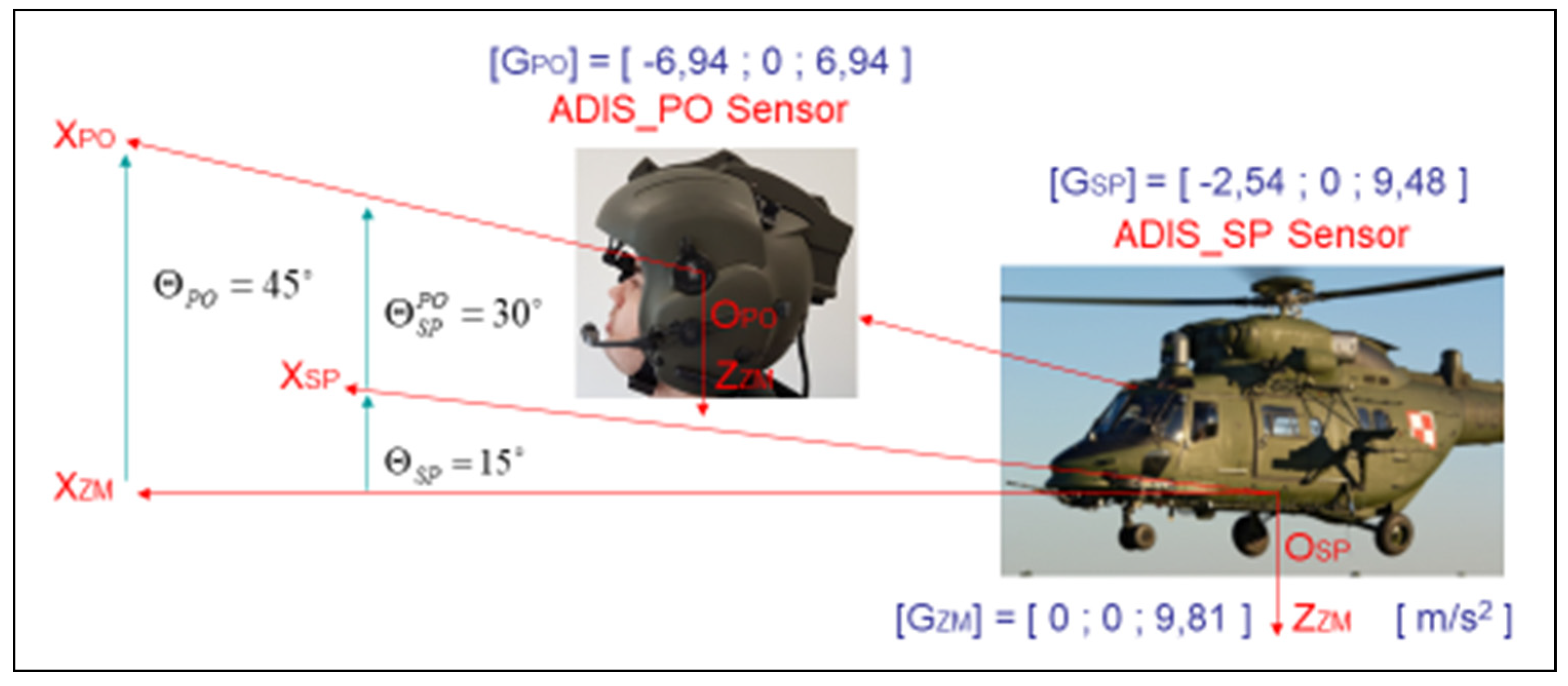
The schematic diagram for visualizing the quaternion method (Figure 3) shows the relative angular positions of the aircraft and the pilot’s helmet in only one channel–pitch. Additionally, as before, it was assumed that the aircraft rotates at an angular velocity of 15°/s, while the pilot’s helmet rotates at an angular velocity of 45°/s.
Figure 3.
Visualization of the quaternion method using linear accelerations (https://bip.itwl.pl/wp-content/uploads/2024/10/Rozprawa-doktorska-P.-Janik.pdf, accessed on 1 October 2024).
The quaternion describing the angular position of an aircraft relative to the Earth can be determined from the following relationship:
where
- —quaternion created from components of Earth’s gravitational field measured by ADIS-16405 sensor connected to aircraft deck. The ADIS16405 iSensor® product is a complete inertial system that includes a triaxal gyroscope, a triaxial accelerometer, and a triaxial magnetometer. The ADIS16405 combines the Analog Devices, Inc. (Norwood, MA, USA), proprietary iMEMS® technology with signal conditioning that optimizes dynamic performance. The factory calibration characterizes each sensor for sensitivity, bias, alignment, and linear acceleration (gyroscope bias). As a result, each sensor has its own dynamic compensation for correction formulas that provide accurate sensor measurements over a temperature range of −40 °C to +85 °C. The magnetometers employ a self correction function to provide accurate bias performance over temperature as well;
- —quaternion specifying the angular position of an aircraft relative to the Earth;
- —quaternion created from the components of Earth’s gravitational field in a navigation system.
Similarly, a quaternion describing the angular position of the pilot’s helmet relative to the Earth can be represented, which can be determined from the following relationship:
where:
- —quaternion created from components of Earth’s gravitational field measured by ADIS-16405 sensor connected to pilot’s helmet;
- —quaternion defining the angular position of the pilot’s helmet relative to the Earth;
- —a quaternion created from the components of Earth’s gravitational field in a navigation system.
After introducing the above designation, the final form was obtained:
and the relationship describing the quaternion of the pilot’s helmet position relative to the aircraft:
2.2. Modeling the Developed Method in the NSC-1 Orion Helmet-Mounted Cueing Systems
In quaternion notation, the components of Equation (4) can be represented as:
Based on the above, Equation (4) can be presented in the following form:
Equation (4) in its detailed form includes four component equations (corresponding to the number of components of the quaternion). To solve the resulting system of equations, an additional fifth equation with a constant value of “+1”, applicable to the normalized quaternion, should be used.
The system of equations thus created allows the determination of individual components of the quaternion defining the spatial orientation angles of the helmet relative to the aircraft cabin. Due to Equation (9), the system of equations has two solutions for the simple quaternion and the conjugate quaternion, which describe the same angular position.
3. Results
The mathematical dependencies of the solution to the system of Equations (5)–(8) in the general case, for any spatial position of the aircraft, take a complex form, but for special cases a simple analytical form can be obtained.
3.1. Normal Horizontal Flight (Cabin Level)
For normal horizontal flight without maneuvers, it was assumed that the onboard sensor measures only the components of the Earth’s gravitational field, while the helmet-mounted sensor measures the components of the Earth’s gravitational field depending on the angular position of the pilot’s helmet. For normal horizontal flight without maneuvers, the complex system of Equations (5)–(8) can be presented in the following form:
3.2. Inverted Horizontal Flight (Cabin on the Horizon)
For inverted horizontal flight without maneuvers, the aircraft’s pitch and yaw angles are equal to “0°”, and its roll angle is “180°”. The onboard sensor (ADIS-16405, AHRS or INS) measures only the components of the Earth’s gravitational field, while the ADIS-16405 (https://www.analog.com/media/en/technical-documentation/data-sheets/ADIS16400_16405.pdf, accessed on 13 March 2021) helmet-mounted sensor measures only the components of the Earth’s gravitational field depending on the angular position of the pilot’s helmet, but in an inverted system.
For inverted horizontal flight, the complex system of Equations (5)–(8) can be presented (after reduction in zero components) in the following form:
Using (9) as an additional relationship, analytical relationships are obtained for individual components of the quaternion of the angular position of the pilot’s helmet relative to the aircraft cabin. The above relations form the basis for modeling selected angular positions of the pilot’s helmet in inverted horizontal flight and for investigating errors in determining the angular position of the pilot’s helmet relative to the aircraft cabin.
4. Discussion
The scope of simulation tests accepted for analysis included determining the errors in determining elevation angles for the Euler angle method and the quaternion method.
It was assumed that the tests would cover the impact of errors in the ADIS-16405 sensor, installed on the pilot’s helmet during flight without maneuvers, and the impact of additional linear accelerations during flight with maneuvers.
Normal Horizontal Flight (Cabin Level) Without Maneuvers
In the first stage, tests were performed for a case where the aircraft flies in a vertical plane (simulated “free” loop–fixed cabin elevation and pilot helmet elevation).
In this case, the components of linear acceleration measured by the ADIS-16405 sensor and the AHRS onboard sensor are components of the Earth’s gravitational field.
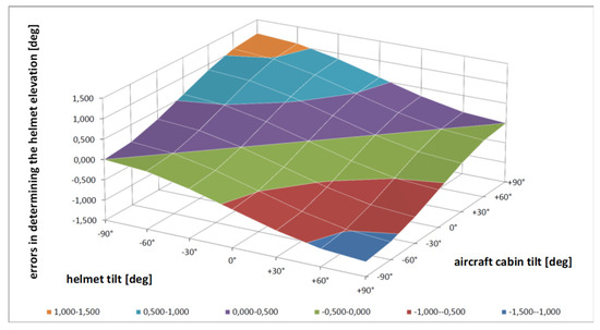
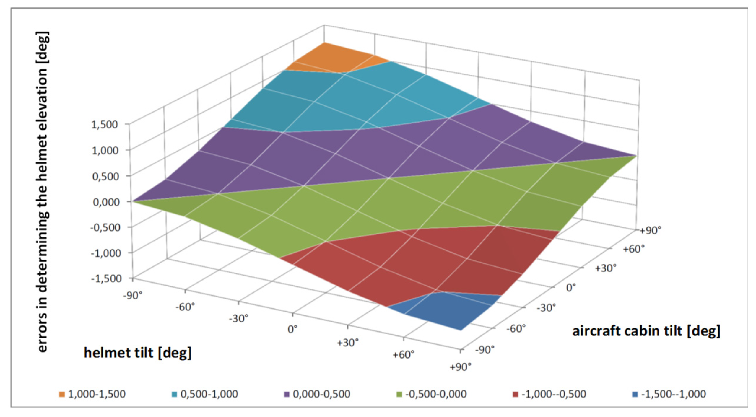
An error of “+0.1 m/s2” was assumed for the ADIS-16405 sensor for the purposes of the study. The results of determining the pilot’s helmet elevation based on linear acceleration measurements for the Euler angles method (Figure 4) showed that the error distributions are variable.
Figure 4.
The course of errors in determining the pilot’s helmet elevation depending on the aircraft’s tilt–Euler angle method–impact of ADIS sensor errors (https://bip.itwl.pl/wp-content/uploads/2024/10/Rozprawa-doktorska-P.-Janik.pdf., accessed on 1 October 2024).
Analysis of the obtained test results showed that the maximum errors in determining the pilot’s helmet elevation reach “<−1.146° ÷ +1.146°>” for the Euler angles method, depending on the aircraft pitch and the pilot’s helmet tilt.
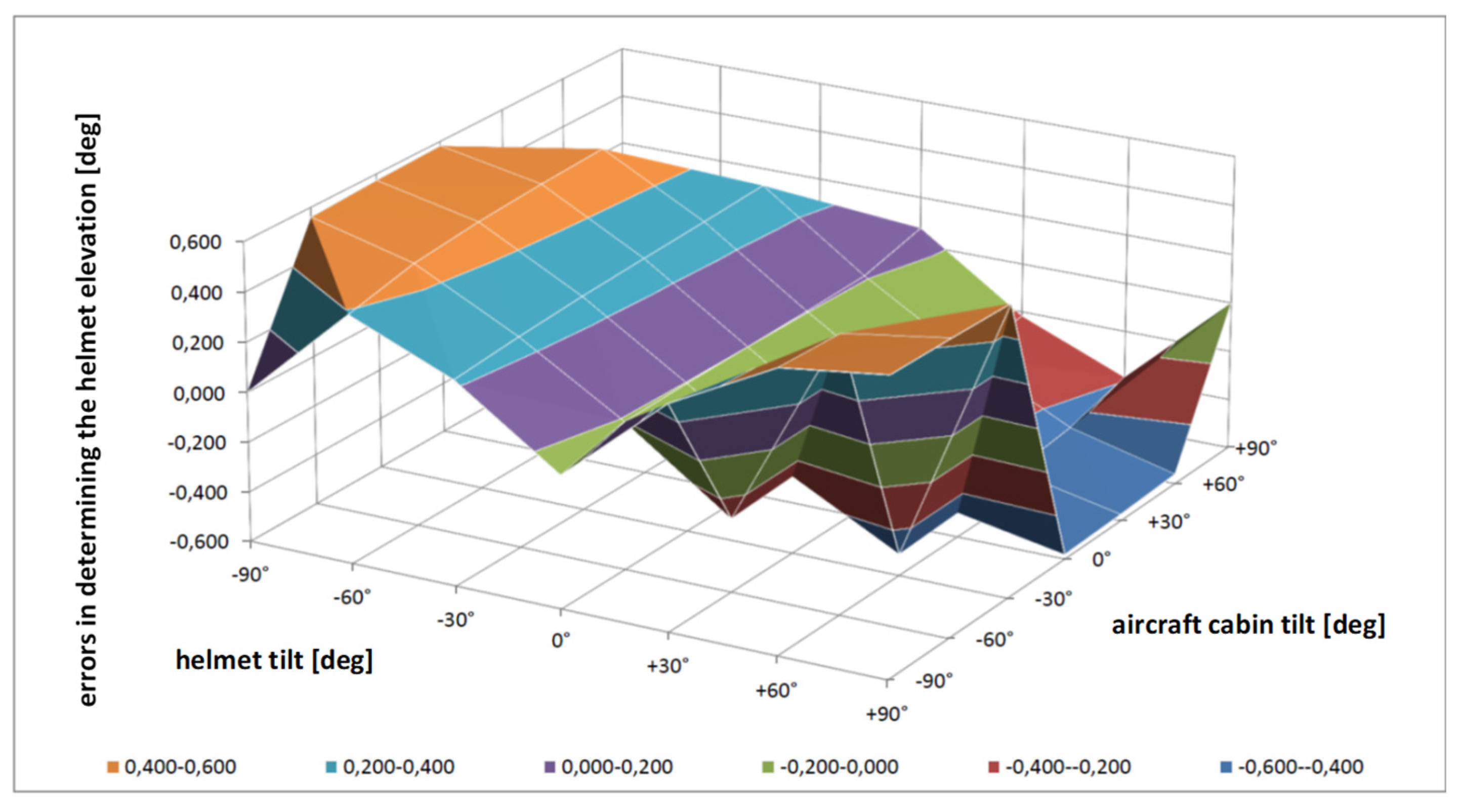
Similar to the Euler angle method, the results for determining the pilot’s helmet elevation based on linear acceleration measurements for the quaternion method (Figure 5) showed that the error distributions are variable.
Figure 5.
The course of errors in determining the pilot’s helmet elevation depending on the aircraft’s tilt–quaternion method–impact of ADIS sensor errors (https://bip.itwl.pl/wp-content/uploads/2024/10/Rozprawa-doktorska-P.-Janik.pdf., accessed on 1 October 2024).
Analysis of the obtained test results showed that the maximum errors in determining the pilot’s helmet elevation reach “<−0.582° ÷ +0.582°>” for the quaternion method, depending on the aircraft’s pitch and the pilot’s helmet tilt. It was confirmed that the quaternion method allows for obtaining errors in determining the pilot’s helmet elevation at a level slightly better than the Euler angle method.
5. Conclusions
The results of the simulation tests confirm the possibility of using quaternions to determine the angular position of a drone (as an aircraft) relative to the navigational coordinate system associated with the horizon. The drone was adapted as a pilot’s helmet and the navigation system as the horizontal position of the aircraft cabin, and then this approach was extended to cases where the aircraft is in positions other than horizontal, which occurs during maneuvers and air combat. It was demonstrated that quaternion methods can be used not only for the horizontal position of the aircraft, but also for any spatial positions of the aircraft and the pilot’s helmet. It has been confirmed that the quaternion method allows for the determination of pilot helmet elevation errors at a level incomparably better than the Euler angle method.
Author Contributions
Conceptualization, A.S. and A.P.; methodology, P.J.; software, A.S. and S.M.; validation, P.J. and A.P. All authors have read and agreed to the published version of the manuscript.
Funding
This research received no external funding.
Institutional Review Board Statement
Not applicable.
Informed Consent Statement
Informed consent was obtained from all subjects involved in the study.
Data Availability Statement
The data presented in this study are available upon request from the corresponding author.
Conflicts of Interest
The authors declare no conflicts of interest.
References
- Pazur, A.; Szelmanowski, A.; Zieja, M.; Janik, P. Estimation of the Angular Positioning Inaccuracy in Avionics Helmet-Mounted Cueing Systems with Magnetic Method. In Methods and Techniques of Signal Proceedings in Physical Measurements; Springer Nature: Cham, Switzerland, 2019; pp. 319–336. [Google Scholar]
- Michalak, S.; Szelmanowski, A.; Pazur, A.; Witoś, M.; Janik, P. Magnetic sensors overviev and their application in the helmet mounted cueing systems. In Proceedings of the 2nd IEEE Conference on Advances in Mgnetics, La Thuile, Italy, 4–7 February 2018. [Google Scholar]
- Ortyl, A.; Gosiewski, Z. The use of quaternion algebra to determine the spatial orientation of aircraft. Mechanika 1995, 45, 289–298. [Google Scholar]
- Mrkley, F.L.; Mortari, D. Quaternion Attitude Estimation Using Vector Observations. J. Astronaut. Sci. 2000, 48, 359–380. [Google Scholar] [CrossRef] [Scilit]
- Szelmanowski, A. NSC-1 Orion Helmet-Mounted Sighting System for Military Helicopters with Integrated Avionics System; Air Force Institute of Technology: Warsaw, Poland, 2013. [Google Scholar]
- Valenti, R.G.; Dryanowski, I.; Xiao, J. Keeping a Good Attitude. A Quaternion-Based Orientation Filter for IMUs and MARGs. Sensors 2015, 15, 19302–19330. [Google Scholar] [CrossRef] [Scilit] [PubMed]
- Tseng, S.; Li, W.; Sheng, C.; Hsu, J.; Chen, C. Motion and Attitude Estimation Using Intertial Measurements with Complementary Filter. In Proceedings of the 2011 8th Asian Control Conference (ASCC), Kaohsiing, Taiwan, 15–18 May 2011; pp. 863–868. [Google Scholar]
- Marins, J.L.; Yun, X.; Bachmann, E.R.; McGhee, R.B.; Zyda, M.J. An extended Kalman filter for quaternion-based orientation estimation using MARG sensors. In Proceedings of the IEEE/RSJ International Conference on Intelligent Robots and Systems, Maui, HI, USA, 29 October–3 November 2001; pp. 2003–2011. [Google Scholar]
- Sabatini, A.M. Quaternion-based extended Kalman filter for determining orientation by inertial and magnetic sensing. IEEE Trans. Biomed. Eng. 2006, 53, 1346–1356. [Google Scholar] [CrossRef] [Scilit] [PubMed]
- Grewal, S.M.; Andrews, P.A.; Bartone, G.C. Global Navigation Satellite Systems, Inertial Navigation, and Integration, 4th ed.; John Wiley & Sons: Hoboken, NJ, USA, 2020. [Google Scholar]
- Lee, H.K.; Lee, J.G.; Roh, Y.K.; Park, C.G. Modeling Quaternion Error in SDINS: Computer Frame Approach. IEEE Trans. Aerosp. Electron. Syst. 1998, 34, 289–300. [Google Scholar] [CrossRef] [Scilit]
- Narkhede, P.; Poddar, S.; Walambe, R.; Ghinea, G. Cascaded Complementary Filter Architecture for Sensor Fusion in Attitude Estimation. Sensors 2021, 21, 1937. [Google Scholar] [CrossRef] [Scilit] [PubMed]
Disclaimer/Publisher’s Note: The statements, opinions and data contained in all publications are solely those of the individual author(s) and contributor(s) and not of MDPI and/or the editor(s). MDPI and/or the editor(s) disclaim responsibility for any injury to people or property resulting from any ideas, methods, instructions or products referred to in the content. |
© 2026 by the authors. Licensee MDPI, Basel, Switzerland. This article is an open access article distributed under the terms and conditions of the Creative Commons Attribution (CC BY) license.