


Abstract
Decarbonizing air travel poses a major technological challenge, driven by the substantial power requirements of the drivetrain and the demanding weight and volume constraints of airborne systems. One promising avenue involves leveraging the high specific energy of hydrogen by designing compact, high-power fuel cell stacks to supply power for electric drivetrains. However, a key drawback of such propulsion architectures is the substantial heat generated within the fuel cells, which necessitates bulky and heavy thermal management systems to ensure safe and continuous operation. This study investigates a proposed air-based thermal management system, which operates by introducing pulsating heat pipes into the bipolar plates of a High-Temperature Polymer Electrolyte Membrane Fuel Cell (HT-PEM FC) stack. If proven to be feasible, heat pipe assisted air cooling may provide the benefit of reducing overall system complexity by decreasing the number of components in the thermal management system. To evaluate the thermal performance of the proposed system, a one-dimensional thermal model was initially developed in a previous study to describe the temperature distribution along the length of a heat pipe. Building upon this foundation, the present work extends the model by incorporating a two-dimensional Computational Fluid Dynamic (CFD) analysis to account for geometry-specific effects within the hexagonal design. Results indicate that the heat transfer from the hexagonal heat pipe geometry to the coolant air flow was marginally overestimated in previous analytical calculations. Revised heat transfer rates led to a shift in the predicted temperature distributions, resulting in the need for either increased external airflow, extended condenser sections, or reduced inlet temperatures to maintain target operating conditions. Although these adjustments may result in a slight increase in system mass and parasitic power consumption, the overall impact is limited, and the heat pipe-assisted air cooling approach remains theoretically feasible. Based on the results, design modifications are proposed and their impact on thermal performance is evaluated to address the challenges of heat rejection and temperature uniformity. A modification based on variation and optimization of PHP meander lengths was evaluated using the updated model and it significantly improved temperature homogeneity across the evaporator.
1. Introduction
As the effects of man-made climate change manifest, many governments around the world have set goals to reduce emissions as codified in the Paris agreement [1]. This shift also applies to the aviation sector, where a large variety of approaches exist to reduce the emissions of aircraft. Roadmaps outlining these research avenues along with emission reduction goals that the aviation industry has set have been published by research as well as governmental institutions [2,3,4].
One central obstacle for the integration of fuel cell stacks that arises when the power demand of the airplane increases with size and passenger capacity is the management of waste heat from the fuel cell system [5,6]. Currently, Polymer Electrolyte Membrane Fuel Cells (PEM-FCs) perform with efficiencies in a range of 40–60% [7,8], with the remainder of the potential stored energy of the fuel being transformed into heat, which needs to be rejected from the system to prevent overheating.
State-of-the-art high-power PEM-FC stacks are cooled using a liquid cooling approach, where a coolant is pumped through designated channels in the bipolar plates of the fuel cell. Liquid thermal management systems provide good thermal performance, which is mainly defined by the ability to maintain a maximum operating temperature as well as minimizing the temperature gradient across the cell to promote homogeneous cell operation. However, they also require numerous supplementary components, such as coolant pumps, feed lines, reservoirs, fans and bulky and heavy heat exchangers. All these subsystems constitute a large amount of necessary integration volume and mass and present many possible points of failure as well as requiring additional parasitic power to operate. These properties inhibit the integration into airborne systems, where weight, volume and reliability are of elevated importance [9]. Therefore, this study investigates an alternative approach to cooling fuel cells using Pulsating Heat Pipes (PHPs). The objective is to assess whether this system can effectively replace the conventional liquid cooling system, potentially reducing the overall weight and volume of the fuel cell system by altering the heat rejection process.
Central to the proposed system is the integration of a PHP with a hexagonal cross section into the bipolar plates of a HT-PEM FC stack. The hot end of the conducting system is in contact with the Membrane Electrode Assembly (MEA) of the cell, where the heat is generated and the cold side extends beyond the core stack and is positioned in an external coolant air flow. A PHP is a heat transfer device that consists of a closed-loop capillary tube partially filled with a working fluid. It leverages the two-phase thermal expansion of the enclosed working fluid and capillary forces to efficiently transport heat along its length [10,11]. This investigation builds on a previous study in which the working principle of the novel heating approach was introduced and preliminary evaluations of the thermal performance were executed [12].
A drawback identified by that study was the presence of significant temperature gradients in the cross-wise direction, which resulted from the heating of the coolant air as it passed along subsequent pipes. This presents a substantial challenge that could hinder the implementation of this coolant approach. To address this issue, Section 2 of this study will explore design strategies for mitigating these temperature gradients. Subsequently, in Section 3 the expansions to the modelling of thermal performance are outlined and the simulation is applied for selected design modifications.
2. Design Modifications
Several modifications to the original PHP-assisted air cooling configuration are introduced, aiming either to enhance the overall heat transfer from the PHP-integrated bipolar plate to the coolant airflow or to improve temperature uniformity across the cell MEA. Selected design modifications are implemented within a 1D numerical model, as presented in Section 3, and the resulting thermal performance is presented in Section 4.
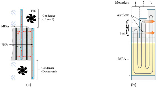
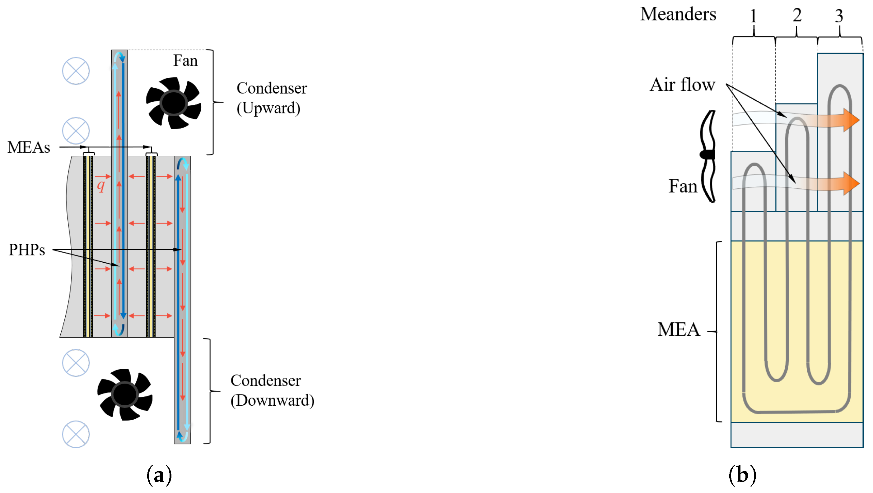
One approach is to alternate the direction in which the condenser section of the PHP extends beyond the core of the fuel cell stack, as shown in Figure 1a. In this way each MEA is cooled by two heat pipes facing in different directions with an air-based heat sink at either end. In the depicted heat sinks, the air flows parallel to the plain of the PHP. In this way the temperature distribution in the membrane would be more homogeneous compared with heat sinks located only at the upper end. In addition, this configuration also increases the spacing between each condenser section, leading to less restricted coolant air flow and more effective heat rejection, which also aids in reducing air heating and cross-wise temperature gradients. On the other hand, this configuration would in turn increase the integration volume of the fuel cell stack and additional air feed systems. And both these effects are detrimental to the integration into highly compact systems, such as those required for aircraft. In addition, numerous studies have investigated the performance of PHPs in different orientations with respect to gravity and determined a notably decreased performance when the heat sink was placed below the heat source [13,14,15].
Figure 1.
Configurations with parallel air flow: (a) with alternating condenser direction and (b) with three meanders of varying length (described by meander numeration on the right hand side).
Another approach to mitigating cross-wise temperature gradients due to air heating is the alteration of PHP-meander (U-turn) lengths across a singular PHP, as shown in Figure 1. By varying the range that each meander extends into the external air flow, the area of the condenser section, which rejects heat, is altered. If the meander is elongated, the respective section will cool down more and vice versa. By locally altering the heat rejection rate in this manner, the thermal distribution in the cross-wise direction may be adapted to benefit temperature uniformity. While heat pipes adhering to this configuration have not been implemented to the authors’ knowledge, the potential for temperature regulation is investigated via simulation in Section 3.
However, the inclusion of pulsating heat pipes will necessarily increase the integration volume of the fuel cell stack as well as the weight of the central system. The larger size and extending heat rejection surfaces of the PHP will also make the integration into a system more complicated, since the coolant air stream needs to be directly adjacent to the stack, while in a liquid-based system the heat exchanger is spacially independent from the fuel cell system, which facilitates design and assembly. Whether this increase in weight and volume can be both offset by the reduced need for auxiliary systems and efficient remains to be determined.
3. Heat Transfer Modelling
For the analysis, a single central hexagonal channel from the proposed baseline of the PHP-integrated bipolar plate is considered [16]. It is divided into an evaporator section within the fuel cell stack and a condenser section exposed to an external airflow. Periodicity in the transverse directions is assumed, meaning that heat transfer is only evaluated along the main axis of the pipe. To enable efficient calculations, several simplifications are applied.
The temperature is considered uniform across the cross section and no heat exchange is assumed between neighboring channels due to symmetry. Radiative heat losses are neglected and the pipe ends in the axial direction are treated as adiabatic. The reactant gases are assumed to be preheated to the operating temperature and heat generation is modeled as uniformly distributed across the MEA at a maximum rate of 1 W , consistent with state-of-the-art performance [17,18]. The external flow around the condenser section is considered as dry air with constant velocity and the cooling air channel is assumed sufficiently wide to ensure uniform flow. The PHP has an internal height of 2 and a wall thickness of and is modeled as a closed system with constant thermal capacity, density and equivalent thermal conductivity. Reported values for the latter vary widely in the literature, typically ranging from 600 to 10,000 W , reflecting differences in geometry, operating conditions and experimental setups [15,19,20,21].
The resulting one-dimensional thermal system is modelled using finite differences to calculate the static temperature distribution along a single hexagonal strand of the PHP. To enable rapid calculation and parameter variation, the convective heat transfer was originally determined with analytical, empirical correlations based on Gnielinski’s [22] work on prismatic shapes in cross flow. For a detailed description of the model and its computational implementation, readers are referred to [12].
However, the preexisting model provided only limited insight into the actual heat transfer for the specific shape of the proposed system. This is because, although the proposed system is similar to a hexagon, its final shape is distinct, which renders the applicability of the correlations as a good approximation rather than an accurate calculation. Additional design modifications, as described above, would further diverge from the simplified assumption of prismatic shapes and therefore make the empirical model unsuited for accurate evaluation.
As a consequence, higher fidelity heat transfer modelling employing CFD is executed for the PHP-based thermal management system. A mesh-independence study is carried out for Reynolds numbers of 100 and 28,000 and wall temperatures of 333.15 K and 473.15 K, representing both laminar and turbulent flow regimes as well as relevant thermal conditions. The results show that the generated meshes can be considered grid-independent, since all variations in the monitored quantities remain below 0.37 percent with further refinement. The numerical simulations in ANSYS Fluent 2024 R1 are performed using the coupled pressure–velocity solver, which solves the continuity equations simultaneously to improve stability and efficiency. Turbulence is modeled with the SST approach, combining the near-wall accuracy of the model with the robustness of in the free stream. Convergence is considered achieved when the residuals of the monitored quantities fall below .
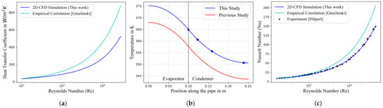
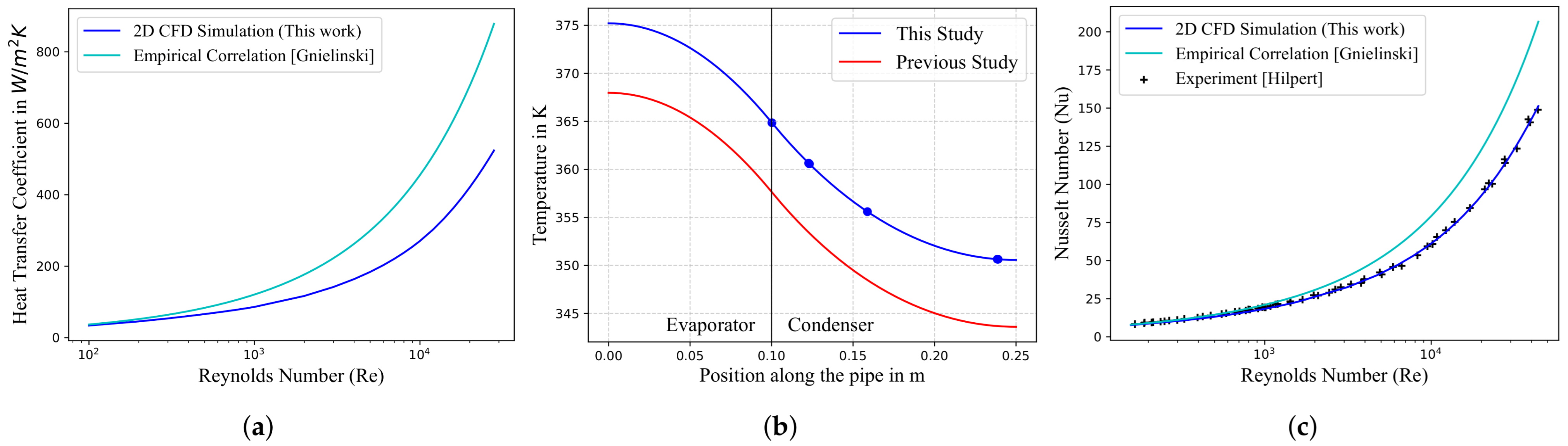
To validate the developed CFD model, a circular cross-section is investigated and the results are compared with both the empirical correlation [23] used in the one-dimensional model and the experimental data reported by Hilpert [24]. The simulations are performed at a constant wall temperature of 473.15 K and the outcomes are presented in Figure 2b. As the Gnielinski correlation defines the characteristic length as the circle diameter multiplied by , the Reynolds and Nusselt numbers from both the simulations and the experimental results are scaled accordingly to ensure consistency.
Figure 2.
(a) Comparison of heat transfer coefficient from the 2D CFD simulation of the hexagonal-like geometry with empirical correlation [23]; (b) comparison of temperature distributions along the heat pipe from the original 1D model and the updated version; (c) circular validation.
For Reynolds numbers below 1000, the three datasets show close agreement. In this regime, the Gnielinski correlation slightly overpredicts the experimental data, whereas the CFD simulations fall just below, indicating that the numerical model provides a conservative prediction in this range. However, at Reynolds numbers above 1000 the correlation deviates from the trend of the other datasets and predicts a steeper increase in Nusselt number. In contrast, the CFD simulations remain in very close agreement with Hilpert’s measurements, accurately capturing the convective behavior in this range.
Overall, the comparison shows that at high wall temperatures the CFD model reproduces the experimental behavior with high accuracy across the studied Reynolds number range. On this basis, the new method for determining the heat transfer coefficient is integrated into the existing one-dimensional model, using the results from the parametric CFD models. This improves the predictive capability of the thermal model for calculating heat distributions in PHP strands.
4. Results
After validating the CFD approach with the circular cross-section, the methodology is applied to the hexagonal-like geometry considered in the proposed thermal management concept. Since the heat transfer coefficient is the parameter that is improved, it is calculated directly within the CFD simulations. To enable a comparison with the Gnielinski correlation, the Nusselt numbers obtained from the correlation are converted into the corresponding heat transfer coefficients. The comparison is shown in Figure 2a, where the CFD simulations are carried out at a constant wall temperature of 473.15 K.
A similar overall trend to the one observed for the circular cross-section in Figure 2b is evident, but the deviation between the approaches begins at much lower Reynolds numbers. Close agreement is only found near Re = 100. With increasing Reynolds number, the results diverge progressively. The Gnielinski correlation again predicts a steeper rise than the CFD simulations. This shows that the existing one-dimensional model, which relies on the correlation, overestimates the heat transfer coefficient.
To assess the implications for the thermal performance of the system, Figure 2b shows the resulting temperature distribution along the heat pipe. The original one-dimensional model is compared with the improved version, which incorporates CFD-derived heat transfer coefficients. In the figure, markers indicate the point from which the CFD-derived values are applied. The simulations are performed with an equivalent thermal conductivity of 3300 , an airspeed of 3 and an inlet air temperature of . The results reveal that the improved model predicts higher operating temperatures, with deviations of about 7 . However, the overall temperature gradient remains unchanged.
The comparison highlights that the use of CFD-derived heat transfer coefficients improves the predictive capability of the model regarding the thermal behavior of the system. Nevertheless, the absence of experimental data for the hexagonal-like geometry limits the ability to fully validate the model, which increases the necessity of further experimental investigations to confirm and refine the presented approach.
Using the updated model to calculate temperature distributions, an investigation of the variable condenser length design modification introduced in Section 2 is carried out. The heating of the coolant air as it passes each pipe is calculated and the resulting temperature increase considered as the inlet temperature for the subsequent pipe. With uniform condenser lengths, this leads to a substantial temperature gradient in the direction of the heating air flow, as was shown in a previous study [12].
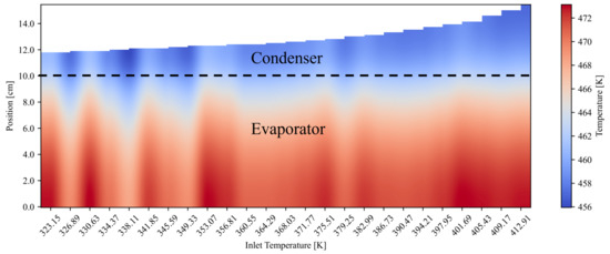
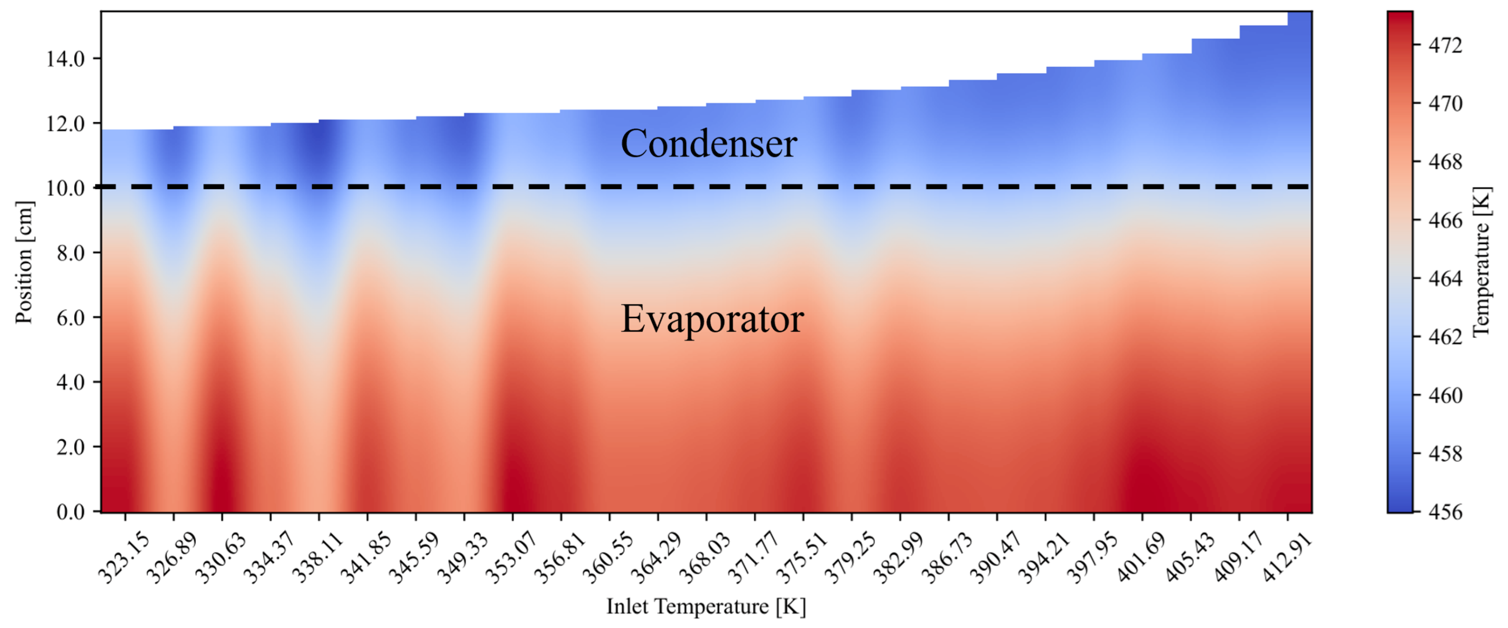
To combat this temperature variation, an optimization is executed that employs the thermal model to calculate the ideal condenser length for each pipe based on the respective air flow temperature and the maximum permissible operating threshold of . To determine the optimal condenser length, an iterative bracketing algorithm was applied. The procedure began with an initial upper and lower bound for the condenser length. For each iteration, the condenser length was set to the midpoint between the bounds, and the resulting maximum temperature was evaluated. If the temperature exceeded the specified threshold, the upper bound was reduced to the current midpoint; if the temperature remained below the threshold, the lower bound was updated accordingly. This process was repeated until the absolute difference between the predicted temperature and the threshold temperature fell below a predefined convergence criterion, while also ensuring that the resulting temperature did not exceed the allowable limit. The resulting heat map is displayed below in Figure 3. Although the peak evaporator temperature in the modified geometry is slightly higher, it is striking that the evaporator exhibits a significantly more homogeneous temperature distribution. Between the hottest and coldest point there exists a temperature drop of .
Figure 3.
Heat map of a PHP with variable optimized condenser lengths; air flow speed = 10 , equivalent thermal conductivity = 1000 , Boundary between evaporator and Condenser depicted via dashed line.
With such a comparatively uniform temperature distribution the PHP-based cooling approach could maintain a membrane at close to ideal operating conditions. Additional modifications like increasing the air channel cross section, integrating fins or increasing the equivalent conductivity may further improve the thermal performance of the proposed system. Additionally, it is noticeable that the length progression of the condenser pipes closely resembles quadratic growth.
While optimizing condenser extensions is a tremendous improvement, it is to be noted that this model does not take into account that the equivalent thermal conductivity and therefore the performance of the PHP may be impacted by the variation in the condenser lengths. Furthermore, the calculations are based on heat transfer calculations with uniform flow, which does not accurately depict the fluid behavior for multiple successive pipes and narrow channels. Future research will refine the model and enable the integration of additional design modifications.
5. Conclusions and Outlook
The feasibility of an alternative method of fuel cell cooling employing PHPs was investigated. A number of design modifications to combat large temperature gradients were introduced. Among these were varying PHP-meander lengths and bidirectional integration of the heat pipes. The modifications were explained, their potential advantages and drawbacks were discussed, and simulations were executed to evaluate their likely thermal performance. For this purpose a numerical 1D model was enhanced by replacing analytical correlations for the calculation of heat transfer coefficients by parametrized CFD analysis. The updated model was validated against experimental data from the literature for a cylindrical reference case and the results show that the previous approach slightly overestimated heat transfer rates from the pipe to the coolant air flow. The model was subsequently applied to the hexagonal geometry of the proposed PHP system, which resulted in a temperature difference of approximately 7 when compared to the empirical approach.
Finally, an optimization of the variable condenser length design modification was carried out, determining the ideal condenser length for each meander of the PHP to maintain operating temperature below for a HT-PEM fuel cell. The optimization drastically improved temperature homogeneity in the evaporator section of the PHP and therefore presents a valuable option for the integration into a fuel cell system.
For upcoming studies, a demonstration of the hexagonal PHP-cooling system will be built and its thermal performance evaluated. The heat transfer calculations put forth in this work will be validated and the model updated according to the experimental results. Additional studies are required to determine the impact of varying condenser length on the internal performance of a heat pipe and therefore evaluate whether it truly is a feasible approach to maintaining an even operating temperature across a larger area.
Author Contributions
Conceptualization, F.F., F.K. and M.K.; methodology, F.F., F.K. and S.K.; software, F.K. and F.F.; validation, F.K.; formal analysis, F.F. and F.K.; resources, S.K.; data curation, F.F. and F.K.; writing—original draft preparation, F.F. and F.K.; writing—review and editing, M.K. and S.K.; visualization, F.F., F.K. and S.K.; supervision, M.K. and S.K.; project administration, M.K. and S.K.; funding acquisition, S.K. All authors have read and agreed to the published version of the manuscript.
Funding
This research received no external funding.
Data Availability Statement
The raw data from the 1D simulations will be made available upon request. The script for the numerical and empirical simulation will also be available on request, under the condition of credit attribution.
Conflicts of Interest
The authors declare no conflicts of interest.
References
- United Nations Framework Convention on Climate Change (Ed.) The Paris Agreement; United Nations Framework Convention on Climate Change: Bonn, Germany, 2016. [Google Scholar]
- European Commission, Directorate-General for Research and Innovataion, Directorate-General for Mobility and Transport. Flightplan 2050: Europe’s Vision for Aviation; Maintaining Global Leadership and Serving Society’s Needs; Report of the High-Level Group on Aviation Research; Publications Office of the European Union: Luxembourg, 2011. [Google Scholar] [CrossRef]
- Deutsches Zentrum für Luft-und Raumfahrt. Auf dem Weg zu einer KLimaverträglichen Luftfahrt: Die Luftfahrtstrategie des DLR; Deutsches Zentrum für Luft-und Raumfahrt: Köln, Germany, 2024. [Google Scholar]
- Air Transport Action Group. Waypoint 2050: Balancing Growth in Connectivity with a Comprehensive Global Air Transport Response to the Climate Emergency. A Vision of Net-Zero Aviation by Mid-Century, 2nd ed.; Air Transport Action Group: Geneva, Switzerland, 2021. [Google Scholar]
- Kazula, S.; de Graaf, S.; Enghardt, L. Review of fuel cell technologies and evaluation of their potential and challenges for electrified propulsion systems in commercial aviation. J. Glob. Power Propuls. Soc. 2023, 7, 43–57. [Google Scholar] [CrossRef] [Scilit]
- de Graaf, S.; Bahrs, V.; Tarbah, N.; Kazula, S. H2Electra-A Platform for comparative analysis of integration concepts for hydrogen-based electric propulsion in regional aircraft. J. Phys. Conf. Ser. 2023, 2716, 012007. [Google Scholar] [CrossRef] [Scilit]
- Nomnqa, M.; Ikhu-Omoregbe, D.; Rabiu, A. Performance evaluation of a HT-PEM fuel cell micro-cogeneration system for domestic application. Energy Syst. 2019, 10, 185–210. [Google Scholar] [CrossRef] [Scilit]
- ZeroAvia. The Future of Zero-Emission Hydrogen Electric Flight. 2024. Available online: https://www.zeroavia.com/za2000/ (accessed on 22 July 2025).
- Franke, F.; Link, A.; Kazula, S. Evaluation of heat transfer technologies for high temperature polymer electrolyte membrane fuel cells as primary power source in a regional aircraft. CEAS Aeronaut. J. 2025. [Google Scholar] [CrossRef] [Scilit]
- Akachi, H. Structure of a Heat Pipe. U.S. Patent No. 4921041, 1 May 1990. [Google Scholar]
- Nikolayev, V.S. Physical principles and state-of-the-art of modeling of the pulsating heat pipe: A review. Appl. Therm. Eng. 2021, 195, 117111. [Google Scholar] [CrossRef] [Scilit]
- Franke, F.; Kober, M.; Kazula, S. Hexagonal Pulsating Heat Pipe for Fuel Cell Integration; Preliminary Design and Evaluation of Thermal Performance - Draft Version under Revision. Case Stud. Therm. Eng. 2025, 2025, 107272. [Google Scholar] [CrossRef] [Scilit]
- Abela, M.; Mameli, M.; Nikolayev, V.; Filippeschi, S. Experimental analysis and transient numerical simulation of a large diameter pulsating heat pipe in microgravity conditions. Int. J. Heat Mass Transf. 2022, 187, 122532. [Google Scholar] [CrossRef] [Scilit]
- Huang, B.; Jian, Q.; Luo, L.; Bai, X. Research on the in-plane temperature distribution in a PEMFC stack integrated with flat-plate heat pipe under different startup strategies and inclination angles. Appl. Therm. Eng. 2020, 179, 115741. [Google Scholar] [CrossRef] [Scilit]
- Ayel, V.; Slobodeniuk, M.; Bertossi, R.; Romestant, C.; Bertin, Y. Flat plate pulsating heat pipes: A review on the thermohydraulic principles, thermal performances and open issues. Appl. Therm. Eng. 2021, 197, 117200. [Google Scholar] [CrossRef] [Scilit]
- Franke, F.; Kazula, S. German Patent: Vorrichtung für eine Brennstoffzelle, Brennstoffzelle und Verfahren zur Herstellung einer Vorrichtung: Deutsches Patent-und Markenamt. Patent Nr.:DE 10 2024 211 417.
- Meng, H.; Song, J.; Guan, P.; Wang, H.; Zhao, W.; Zou, Y.; Ding, H.; Wu, X.; He, P.; Liu, F.; et al. High ion exchange capacity perfluorosulfonic acid resine proton exchange membrane for high temperature applications in polymer electrolyte fuel cells. J. Power Sources 2024, 602, 234205. [Google Scholar] [CrossRef] [Scilit]
- Ju, Q.; Chao, G.; Guo, T.; Lv, Z.; Li, R.; Geng, K.; Li, N. Effect of solvent-free membranes-forming processes on HT-PEM properties of highly soluble polybenzimidazole. J. Membr. Sci. 2024, 692, 122264. [Google Scholar] [CrossRef] [Scilit]
- Jang, D.S.; Kim, D.; Hong, S.H.; Kim, Y. Comparative thermal performance evaluation between ultrathin flat plate pulsating heat pipe and graphite sheet for mobile electronic devices at various operating conditions. Appl. Therm. Eng. 2019, 149, 1427–1434. [Google Scholar] [CrossRef] [Scilit]
- Wits, W.W.; Groeneveld, G.; van Gerner, H.J. Experimental Investigation of a Flat-Plate Closed-Loop Pulsating Heat Pipe. J. Heat Transf. 2019, 141, 091807. [Google Scholar] [CrossRef] [Scilit]
- Kearney, D.J.; Suleman, O.; Griffin, J.; Mavrakis, G. Thermal performance of a PCB embedded pulsating heat pipe for power electronics applications. Appl. Therm. Eng. 2016, 98, 798–809. [Google Scholar] [CrossRef] [Scilit]
- Stephan, P.; Kabelac, S.; Kind, M.; Mewes, D.; Schaber, K.; Wetzel, T. VDI-Wärmeatlas; Springer: Berlin/Heidelberg, Germany, 2019. [Google Scholar] [CrossRef] [Scilit]
- Gnielinski, V. Berechnung mittlerer Wärme- und Stoffübergangskoeffizienten an laminar und turbulent überströmten Einzelkörpern mit Hilfe einer einheitlichen Gleichung. Forsch. Ingenieurwesen A 1975, 41, 145–153. [Google Scholar] [CrossRef] [Scilit]
- Hilpert, R. Wärmeabgabe von geheizten Drähten und Rohren im Luftstrom. Forsch. Geb. Ingenieurwesens A 1933, 4, 215–224. [Google Scholar] [CrossRef] [Scilit]
Disclaimer/Publisher’s Note: The statements, opinions and data contained in all publications are solely those of the individual author(s) and contributor(s) and not of MDPI and/or the editor(s). MDPI and/or the editor(s) disclaim responsibility for any injury to people or property resulting from any ideas, methods, instructions or products referred to in the content. |
© 2026 by the authors. Licensee MDPI, Basel, Switzerland. This article is an open access article distributed under the terms and conditions of the Creative Commons Attribution (CC BY) license.