


Abstract
The aviation industry is under increasing pressure to enhance sustainability by improving energy efficiency and reducing climate impact. A promising approach is to reduce aerodynamic drag using laminar flow technologies, particularly Natural Laminar Flow (NLF) and Hybrid Laminar Flow Control (HLFC). Previous research has primarily focused on aerodynamic performance, often considering only one technology at a time, using simplified HLFC system design models, and targeting long-range aircraft. This study adopts a more holistic approach by conducting a conceptual design of a short-medium range (SMR) aircraft equipped with both NLF and HLFC. The technologies are applied to the wing and empennage, with detailed HLFC system modelling integrated into the conceptual design process using established methods. A failure analysis is also performed to assess the performance impact of potential malfunctions. Results indicate that combining NLF and HLFC can reduce fuel consumption by 5.9% on the design mission compared to a fully turbulent reference aircraft. Moreover, selectively applying the technologies to specific components enhances fuel savings while reducing system complexity. These findings demonstrate the potential of laminar flow technologies to improve fuel efficiency in SMR aircraft and highlight the importance of integrated aerodynamic and systems-level evaluation.
1. Introduction
The primary objective of the aviation industry today is to reduce its global climate impact. Reducing fuel consumption not only decreases operational costs, but also improves the sector’s economic sustainability and resilience by reducing its sensitivity to future increases in fuel prices. The need for greater energy efficiency highlights the potential of innovative technologies to deliver these benefits in the next generation of passenger aircraft. Two such technologies are natural laminar flow (NLF) and hybrid laminar flow control (HLFC), both of which belong to the category of laminar flow technologies.
This paper contributes to the ongoing assessment of laminar technologies by presenting a conceptual design for a short-medium range (SMR) aircraft equipped with NLF and HLFC. The sizing process accounts for the effects of both technologies. For the HLFC system, this will be achieved by employing an approach analogous to that introduced by Risse [1]. Specifically, HLFC system design and evaluation will be integrated into the preliminary aircraft sizing process using the methodology proposed by Pe et al. [2]. The aircraft will also be designed for an SMR mission with a fixed set of top-level aircraft requirements (TLARs) based on an existing aircraft that is currently operating in this market sector. The design process will leverage the advantages of NLF and HLFC by considering their combined application at aircraft and component levels. The components for which these technologies will be applied include the wing, vertical tail plane (VTP), and horizontal tail plane (HTP).
What fuel savings can be expected from the application of laminar flow technologies to a short-to-medium range aircraft with a fixed set of top-level requirements when considering a realistic laminar flow system design in the aircraft sizing process?
2. Methodology
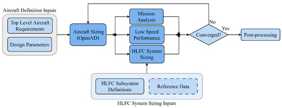
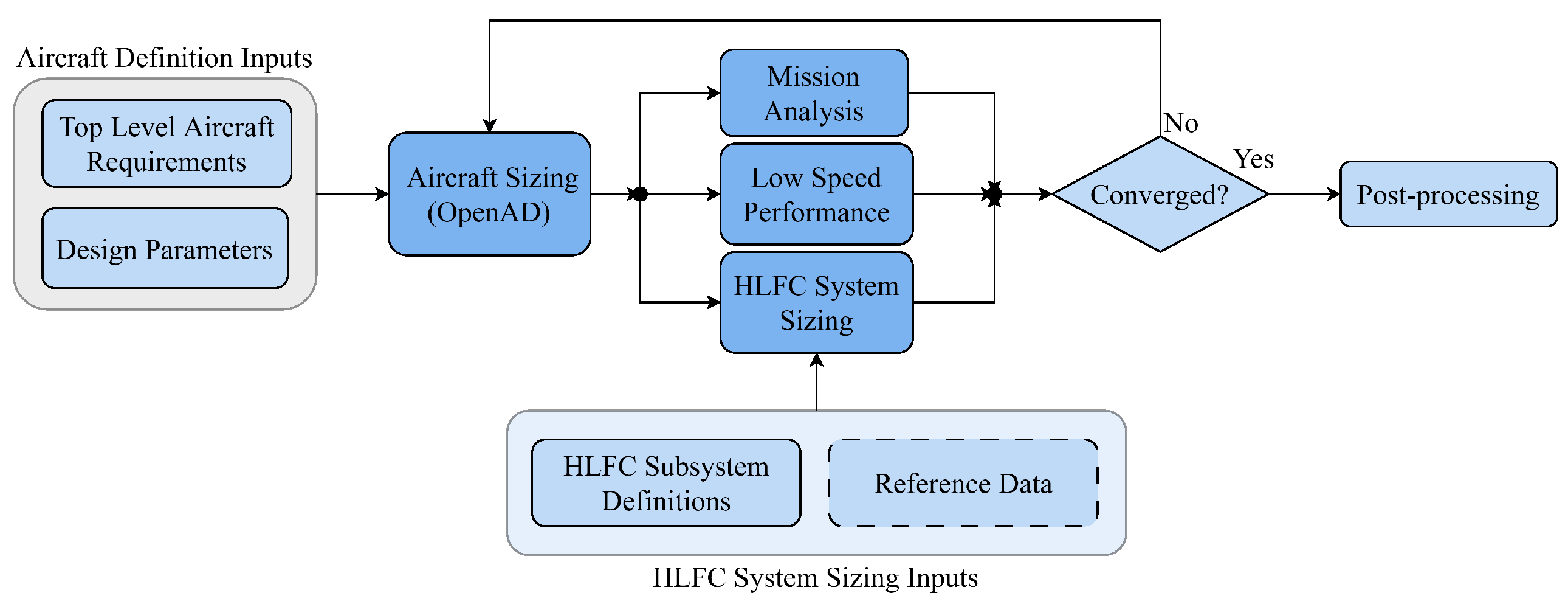
The aircraft concepts presented in this paper are developed using integrated conceptual aircraft design and analysis tools, all of which were developed in-house by the DLR [3]. A flowchart that represents the workflow utilized in this study is provided in Figure 1. This flowchart shows the main tools used and their integration into a conceptual aircraft sizing process. The subsequent chapters provide an overview of the function and general operating principle of each tool employed in the workflow.
Figure 1.
Aircraft design process for laminar tailored aircraft.
2.1. Aircraft Sizing
The central component of the workflow is the conceptual aircraft sizing tool OpenAD [3], which integrates a variety of conventional aircraft sizing methods into a robust, iterative process. This low-fidelity tool uses well-known aircraft design literature based on empirical and semi-empirical methods that have been validated for a wide range of aircraft sizes. OpenAD offers extensive capabilities for designing aircraft concepts using various configurations and layouts, as well as different types of propulsion architecture, including turboprop and turbofan engines. In the current workflow, OpenAD performs preliminary aircraft sizing and generates the resulting aircraft definition, including aerodynamic polars and engine performance data.
2.2. Aircraft Performance Analysis
Mission calculations are performed using an analytical tool that enables two-dimensional simulation and an assessment of an aircraft’s mission. The objective is to determine the fuel consumption for each flight phase, including the reserve mission. The tool also optimises fuel consumption by selecting the optimal initial cruise altitude and performing an optimal stepwise increase in cruise altitude. The main result of the tool is the estimation of fuel required for the various flight phases, as well as the values of the major flight performance parameters. A second analysis tool is used to evaluate the aircraft’s low-speed performance. It estimates parameters, including take-off and landing field lengths, under different operating conditions. One particularly important result of the tool is the balanced field length (BFL), which is used to determine the maximum thrust requirement for engine sizing.
2.3. Laminar Flow Technology Integration
In order to calculate the zero-lift drag, a component buildup method as described by Raymer [4] is used. This method involves calculating the component’s friction drag using a weighted sum of the turbulent and laminar values of the equivalent flat-plate friction coefficients. The weights correspond to the fraction of the component’s wetted area exposed to the turbulent or laminar flow, relative to its total wetted area:
Equation (1) also introduces a new parameter called nLam, defined as:
The nLam parameter expresses the extent to which laminar technologies can provide laminar flow for different configurations and flight conditions. Therefore, it is essential to obtain an accurate estimation of the nLam value for the given component and assumed transition point location in order to obtain an accurate aerodynamic polar and, consequently, an accurate estimation of the fuel saving potential.
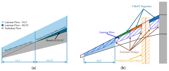
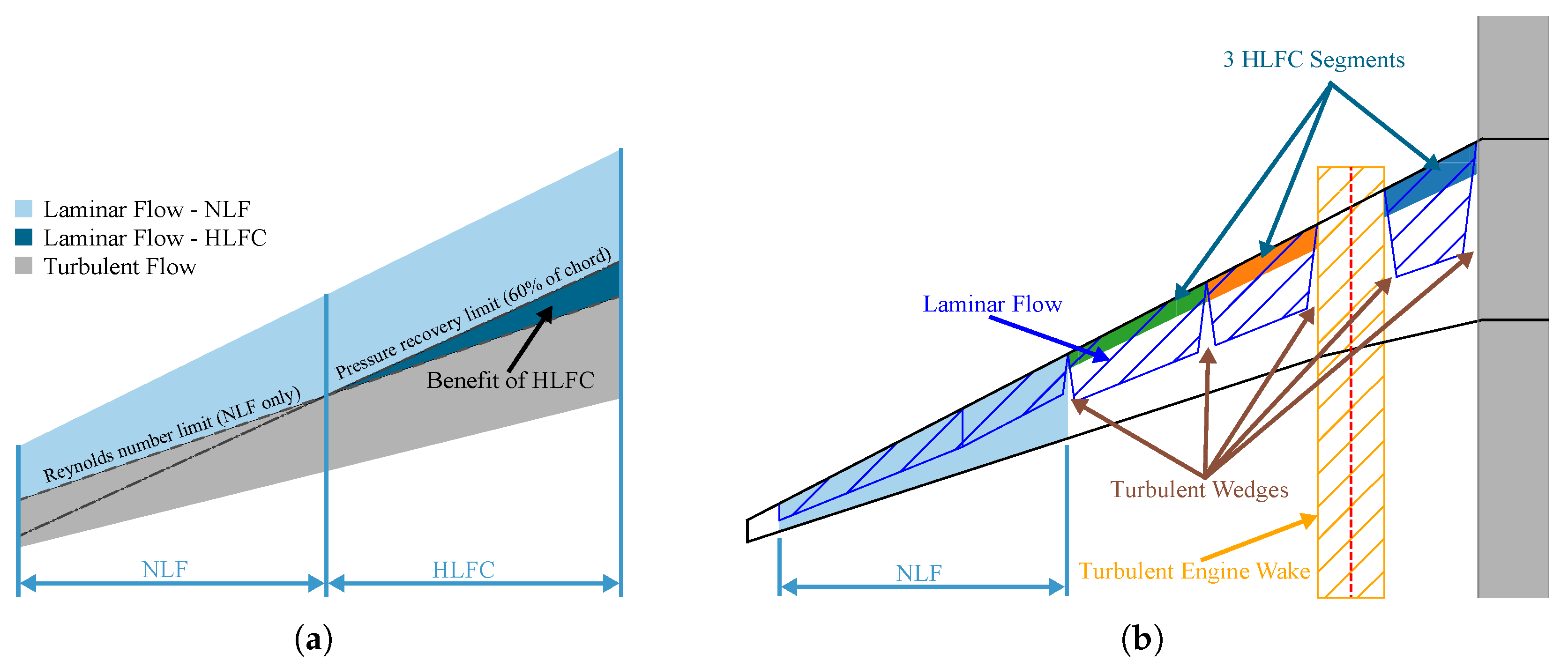
To estimate the transition location in the context of NLF, a methodology proposed by Wilson [5] is employed. This method assumes that the transition from laminar to turbulent flow at any given location is caused by one of two factors (see Figure 2a). The first potential cause is reaching the transition Reynolds number. The second factor limiting the extent of laminar flow over a given component is the location of pressure recovery. To prevent transition due to an unfavourable pressure gradient, NLF aerofoils are designed to maintain a favourable pressure gradient over most of their chord.
Figure 2.
Laminar flow integrated on the wing. (a) Transition model utilized for NLF; (b) NLF and HLFC subsystem configuration on the wing.
For components equipped with HLFC systems, it is assumed that the flow transition will be postponed until the pressure recovery location. This location is assumed to be 60% of the chord length for all components and across all flight conditions. An additional consideration for all HLFC suction segments is the presence of turbulent wedges. These are regions of turbulent flow that originate at the leading edge due to a physical gap in the spanwise edges of each suction panel. Figure 2b illustrates the integration of both NLF and HLFC on a wing with three HLFC segments, as well as the formation of turbulent wedges between the segments.
To design and analyse HLFC systems for different components, a purpose-built tool is incorporated into the workflow. This tool estimates the mass and power off-takes of an HLFC system using the methodology developed by Pe et al. [2]. In order to obtain a more precise estimation of the power off-takes, the amount of suction is interpolated from the findings of previous research [6]. Additionally, the HLFC sizing tool’s functionality has been expanded to include calculating the nLam parameter for NLF and HLFC configurations of wing and empennage, as outlined above.
It is also assumed that both the NLF and the HLFC will provide laminar flow exclusively during the cruise phase, while maintaining the default turbulent nLam values for the other phases of the mission. This conservative approach is based on the recognition that additional factors may become relevant in other mission phases, which could significantly reduce the achievable extent of laminar flow. However, an accurate assessment of these factors would require a more detailed analysis. Such effects include the deflection of high-lift devices, ice formation or early transition due to flight through clouds.
3. Reference and Baseline Aircraft
As the SMR aircraft category currently produces more than half of total CO2 emissions [7], technological advancements would significantly impact the industry’s ability to achieve its climate goals. The Airbus A321neo has been identified as a representative of this category and was redesigned based on publicly available literature [8]. The TLARs have also been extracted and can be found in Table 1. Derived from the A321neo, the research baseline with an entry into service (EIS) date of 2035, called the DLR-F25, was developed by Woehler et al. [9] and serves as the starting point for all laminar aircraft concepts. The performance of the new aircraft concepts is then evaluated in comparison with the DLR-F25. Note that the laminar aircraft concepts developed in this study are also based on the TLARs of the reference aircraft presented in Table 1 and remain fixed throughout the conceptual design process.
Table 1.
TLARs for Airbus A321neo [9].
4. Results and Discussion
To create the laminar aircraft concept, the different types of laminar flow technology are gradually introduced to the wing, HTP, and VTP, and then compared with each other. Next, a comparative analysis between the baseline aircraft and the final configuration with integrated laminar flow technologies is provided. This section concludes by conducting a failure analysis where the impact of various failure scenarios on the aircraft’s performance is assessed.
4.1. Integration of Laminar Flow Technologies on Individual Components
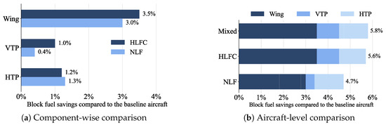
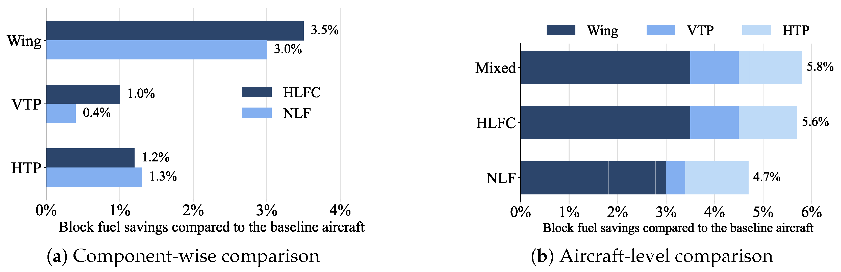
The impact of NLF and HLFC on the wing and empennage is analysed on a component level. Figure 3a indicates that both the wing and the VTP are benefiting most from HLFC compared to NLF. However, for the HTP, NLF outperforms HLFC. This results from the relatively low sweep and high aspect ratio of the HTP, which enables NLF to achieve a value of nLam close to that delivered by HLFC, without the additional penalties of system mass and power off-takes. Therefore, HLFC is utilised on the wing and the VTP, while NLF is used on the HTP and is referred to as the “mixed” configuration.
Figure 3.
Block fuel reduction potential.
Figure 3b compares the mixed configuration with the purely HLFC and NLF configurations and shows an additional block fuel saving of 0.3%. While the magnitude of the additional fuel savings is not particularly large when compared to the pure HLFC option, the mixed configuration offers the additional benefit of eliminating an entire HLFC subsystem and the associated design, production, and maintenance costs.
4.2. Combined Application of HLFC and NLF on the Wing
In the development of the laminar aircraft concept, the potential for combining HLFC and NLF technologies on the wing is being explored. Beyond a certain spanwise location, the extent of laminar flow is constrained by the pressure recovery limit at 60% of the chord. Given that the pressure recovery was assumed to occur at the same chord percentage for both NLF and HLFC, it has been concluded that beyond this spanwise location, HLFC does not offer any additional laminar benefits compared to NLF. Additional fuel savings could be achieved if this region were laminarised through NLF instead of HLFC, which would require additional system power and mass. The objective of this analysis is, therefore, to identify the optimal spanwise location where laminarisation through HLFC should end and NLF should start, and to quantify the resulting benefit in block fuel savings when compared to configurations equipped with a wing featuring only one of the technologies at a time. Furthermore, two HLFC system configurations are evaluated in this analysis, with the objective of investigating the potential for further increasing the fuel savings and reducing the complexity of the suction system.
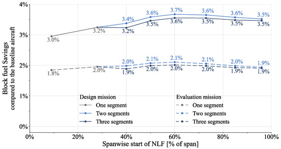
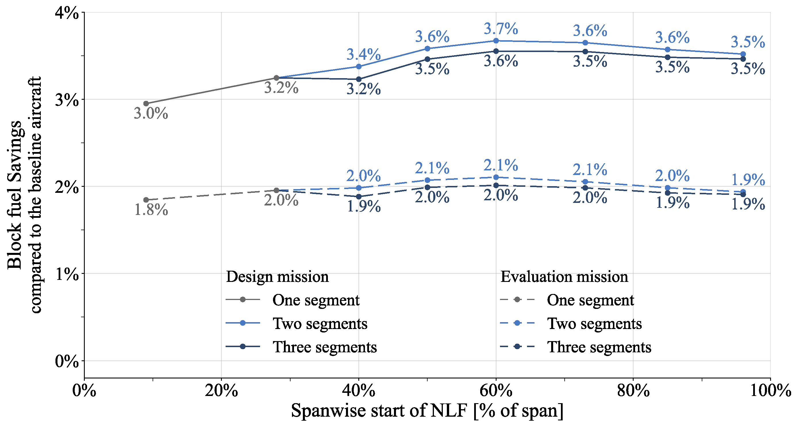
Figure 4 presents the block fuel savings obtained for different proportions of HLFC and NLF on both the design and evaluation missions. The leftmost point of each curve represents the scenario in which the wing was laminarised purely by NLF, while the point at the right end of each curve represents the pure HLFC scenario. Two sets of curves for each mission are shown, representing the two- and three-segment HLFC system configurations. A local maximum in the block fuel savings is reached when the start of NLF is placed at 60% of the span. Beyond this point, extending the HLFC segments leads to an increase in block fuel for both configurations. This indicates that when HLFC is extended beyond 60% of the span, the increase in laminarity is insufficient to justify the additional mass and power penalties. Additionally, it can be observed that the 3-segment configuration consistently demonstrates lower benefits than the 2-segment configuration. The 2-segment configuration also offers a notable reduction in the complexity of the system but with the disadvantage that a segment failure would have caused a significant loss of laminar flow.
Figure 4.
Block fuel savings obtained for different hybrid wing configurations.
4.3. Final Laminar Aircraft Concept
The final laminar aircraft concept is developed by applying the most suitable laminar-flow technologies and compared to the baseline aircraft. Specifically, NLF is applied to the HTP, HLFC to the VTP, and a combination of both technologies to the wing. The hybrid wing incorporates an HLFC system with two suction segments extending to 60% of the span, while the remaining span is laminarised using NLF. Table 2 provides a comparison of key parameters between the final laminar aircraft and the baseline aircraft, which serves as the starting point in this process. Table 2 shows that the total block fuel savings achieved are 5.9% on the design mission. These savings result from the observed 9.2% increase in lift-over-drag ratio, driven by a reduction in drag by 8.5%, due to the decrease in friction drag achieved through the application of laminar flow technologies. Furthermore, the operating empty mass increases by 0.4%, primarily due to the additional mass of the HLFC subsystems, which is also reflected in the increased systems mass. Additionally, the thrust-specific fuel consumption increases by 1.6% as a result of the additional power off-takes for the HLFC system.
Table 2.
Updated comparison of the key characteristics of the laminar aircraft concept to the DLR-F25.
4.4. Failure Analysis
Following the convergence of the final laminar aircraft design, a failure analysis is conducted to assess the impact on block fuel consumption resulting from potential component failures of the laminar-flow technologies. This analysis provides critical insight into developing mitigation strategies, fuelling policies, and evaluating economic feasibility. In this analysis, the aircraft design is considered to be fixed and is not resized.
Table 3 presents the calculated differences in block fuel for different scenarios, ranked by magnitude and expressed relative to the fully functional laminar aircraft and the turbulent baseline. For each failure scenario, the take-off fuel required to complete the full mission is calculated on the assumption that the failure would be detected before departure, allowing the fuel load to be adjusted accordingly. All scenarios were assumed to affect the entire cruise phase. As mentioned earlier, the laminar technologies (or their failure) did not affect the aircraft’s performance in the other mission segments.
Table 3.
Calculated block fuel increase for different failure scenarios.
Based on these findings, the following conclusions can be drawn:
- In the worst-case and extremely unlikely scenario of a combined failure of all HLFC systems with power off-takes still present, along with contamination of all NLF surfaces, the required block fuel would increase by 4.1% (scenario 1).
- The laminar aircraft concept outperforms the turbulent baseline aircraft in terms of block fuel required in all considered failure scenarios, except for the highly improbable operation in a fully turbulent regime (Scenarios 1 and 2).
- Turning off a failed HLFC subsystem is not critical. Even in the extremely improbable event of a failure of all HLFC subsystems, the fuel increase is reduced by only 0.3% when all compressors are turned off (Scenarios 3 and 4).
- The largest expected increase in block fuel due to the failure of a single HLFC subsystem is 1.9%, occurring in the case of the highly improbable failure of the full wing subsystem with power off-takes still present (Scenario 5).
- The maximum expected increase in block fuel resulting from the possible contamination of all NLF surfaces is 1.5% (Scenario 7).
- The most probable increase in block fuel resulting from the failure of any laminar technology on a single component is approximately 0.7% (Scenarios 8–11).
5. Conclusions
The present investigation quantified the realistic block-fuel saving potential that an SMR aircraft can obtain by integrating NLF and HLFC with an assumed EIS in 2035. Using the same set of TLARs as a turbulent baseline aircraft, the analysis revealed potential savings of 5.9% on the design mission and 3.4% on the shorter evaluation mission, demonstrating that laminar flow technologies can deliver substantial fuel-efficiency gains even for SMR platforms. By selecting the most appropriate laminar flow technology for each component, the study showed that a leaner HLFC deployment is possible, which reduces system complexity and yields a modest increase in fuel efficiency. Moreover, a synergistic pairing of NLF and HLFC on the wing produces further savings and simplifies the overall system. The failure-analysis results indicate that a partial loss of laminarity would raise block fuel by only 0.7% for the most probable scenario. The most severe failure of a single HLFC subsystem would add 1.7%, and contamination of all NLF surfaces would increase fuel consumption by 1.5%, providing a useful baseline for fuel-planning strategies.
The primary limitations stem from the lack of high-fidelity aerodynamic simulations and the reliance on HLFC data from previous studies, which prevent precise prediction of transition behaviour and the relationship between the amount of suction applied and the resulting transition location on components equipped with HLFC. Future work should also explore passive HLFC concepts that eliminate power off-take penalties, conduct detailed aerodynamic studies to validate NLF application in the wingtip region, and extend the methodology to other configurations, such as forward-swept or truss-braced wings that are especially suitable for laminar flow technologies.
Author Contributions
Conceptualization, P.M., B.M.H.J.F. and M.F.M.H.; methodology, P.M.; software, P.M.; validation, P.M.; formal analysis, P.M.; investigation, P.M.; resources, T.Z.; data curation, B.M.H.J.F.; writing—original draft preparation, P.M.; writing—review and editing, P.M., B.M.H.J.F., M.F.M.H. and T.Z.; visualization, P.M.; supervision, B.M.H.J.F., M.F.M.H. and T.Z.; project administration, B.M.H.J.F.; funding acquisition, T.Z. All authors have read and agreed to the published version of the manuscript.
Funding
This research received no external funding.
Institutional Review Board Statement
Not applicable.
Informed Consent Statement
Not applicable.
Data Availability Statement
Data are unavailable due to privacy or ethical restrictions.
Conflicts of Interest
The authors declare no conflicts of interest.
References
- Risse, K. Preliminary Overall Aircraft Design with Hybrid Laminar Flow Control. Ph.D. Thesis, Rheinisch-Westfälische Technische Hochschule Aachen, Aachen, Germany, 2016. Available online: https://publications.rwth-aachen.de/record/682719/files/682719.pdf (accessed on 5 September 2025).
- Pe, T.; Thielecke, F. Synthesis and Topology Study of HLFC System Architecturesin Preliminary Aircraft Design. In Proceedings of the 3rd CEAS Air&Space Conference, 21st AIDAA Congress, Venice, Italy, 24–28 October 2011; Available online: https://www.aidaa.it/wp-content/uploads/2021/02/CEAS-2011-Post-Conference-Proceeedings_ISBN.pdf (accessed on 17 September 2025).
- Wöhler, S.; Atanasov, G.; Silberhorn, D.; Fröhler, B.; Zill, T. Preliminary Aircraft Design within a Multidisciplinary and Multifidelity Design Environment. In Proceedings of the Aerospace Europe Conference 2020, Bordeaux, France, 25–28 February 2020; Available online: https://elib.dlr.de/185515/ (accessed on 13 April 2026).
- Raymer, D. Aircraft Design: A Conceptual Approach; American Institute of Aeronautics and Astronautics, Inc.: Reston, VA, USA, 2018. [Google Scholar] [CrossRef] [Scilit]
- Wilson, R. The Introduction of Laminar Flow to the Design and Optimisation of Transport Aircraft. Ph.D. Thesis, Cranfield University, Bedford, UK, 1997. Available online: https://dspace.lib.cranfield.ac.uk/items/981124a2-37bf-40f7-aa71-034fc1e6ca29 (accessed on 17 September 2025).
- Fröhler, B.M.H.J.; Pohya, A.A.; Häßy, J.; Kilian, T.; Bismark, A.H.; Radestock, M.; Cruz Palacios, D. Performance and economic assessment of a wing-integrated hybrid laminar flow control system. Aeronaut. J. 2025, 129, 2103–2130. [Google Scholar] [CrossRef] [Scilit]
- Graver, B.; Rutherford, D.; Zheng, S. CO2 Emissions from Commercial Aviation: 2013, 2018, and 2019. Tech. Rep., The International Council on Clean Aviation, 2020. Available online: https://theicct.org/publication/co2-emissions-from-commercial-aviation-2013-2018-and-2019/ (accessed on 17 September 2025).
- AIRBUS S.A.S. A321. Aircraft Characteristics, Airport and Maintenance Planning. Customer Services, Technical Data Support and Services, 31707 Blagnac Cedex, France, Dec 01/23. Available online: https://aircraft.airbus.com/sites/g/files/jlcbta126/files/2023-12/ac_a321_1223.pdf (accessed on 17 September 2025).
- Wöhler, S.; Häßy, J.; Kriewall, V. Establishing the DLR-F25 as a Research Baseline Aircraft for the Short-Medium Range Market in 2035. In Proceedings of the 33th Congress of the International Council of the Aeronautical Sciences, ICAS 2024, Florence, Italy, 9–13 September 2024; Available online: https://www.icas.org/icas_archive/icas2024/data/preview/icas2024_0398.htm (accessed on 17 September 2025).

Disclaimer/Publisher’s Note: The statements, opinions and data contained in all publications are solely those of the individual author(s) and contributor(s) and not of MDPI and/or the editor(s). MDPI and/or the editor(s) disclaim responsibility for any injury to people or property resulting from any ideas, methods, instructions or products referred to in the content. |
© 2026 by the authors. Licensee MDPI, Basel, Switzerland. This article is an open access article distributed under the terms and conditions of the Creative Commons Attribution (CC BY) license.