


Abstract
This study investigates the integration of hybrid-electric distributed propulsion (DEP) systems in aviation to improve environmental sustainability. It aims to develop practical and integrated aircraft solutions by addressing the architectural complexity of hybrid-electric systems through a concurrent design approach. This approach is crucial due to the strong interdependence between aircraft performance and the size of the hybridized propulsion system. The research utilizes a multi-disciplinary Design and Optimisation (MDO) framework, built around GEMSEO, to support aero-structural and system design for a hybrid-electric regional aircraft configuration. The framework combines aerodynamics, structural, and on-board system design using a multi-fidelity approach, facilitating the integration of different design disciplines. Key findings highlight the sensitivity of overall aircraft design to on-board system sizing. We conclude that a concurrent MDO design approach effectively captures the sensitivity of the design to on-board systems sizing.
1. Introduction
Propeller-driven regional aircraft are essential to ensuring that the aviation sector meets next-generation aviation demands. Advancements in design and propulsion are crucial to these configurations. Traditional aircraft use conventional energy, but achieving net-zero emissions requires innovative designs and alternative fuels like SAF and hydrogen [1]. Hybrid engines, though less efficient, can exploit multiple energy sources. Designing next-generation aircraft involves upgrading propulsion systems and using holistic methodologies to capture system interactions. The computational advancements of recent decades enable aircraft design optimisation, exploiting higher-fidelity methods that unfortunately remain too computationally demanding at the present moment for use in multi-disciplinary, tightly coupled approaches. Multi-fidelity methods and surrogate models can reduce computational costs at the expense of slightly lower accuracy. Addressing these challenges is key to developing efficient and sustainable regional aircraft.
This study applies a flexible design framework to propeller-driven regional aircraft, focusing on low-emission configurations using combustion and hybrid engines powered by SAF, electric batteries, and fuel cells. The approach integrates models from various disciplines, including aerodynamics, structures, mass estimation, and hybrid propulsion, with surrogate models that accelerate the computations for multiple design assessments. Optimisation algorithms are crucial to finding the optimal configurations. Global optimisation methods, though feasible, often use low-fidelity models, resulting in partially feasible designs. Including predictions based on high-fidelity models, even through surrogate modelling, can improve the accuracy.
In this paper, we present a comprehensive multi-disciplinary analysis focused on the Hybrid-Electric Regional Aircraft (HERA) distributed propulsion configuration, specifically Use Case ‘B’ (UCB) [2]. Our analysis leverages concurrent aero-structural and system sizing, employing models with different fidelities. This method involves using surrogate models for certain disciplines, such as aerodynamic, stability, and control models, which are evaluated using a mid-fidelity aerodynamic solver. Constraints are established based on certification requirements, and the aircraft trim is also incorporated into the process. This framework accelerates the convergence towards a feasible and optimized design space, potentially reducing the need for costly redesigns in later development stages.
2. Multi-Disciplinary Framework
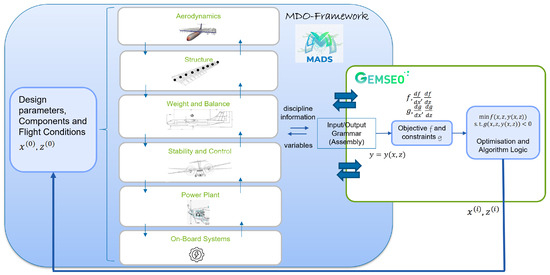
This section details the multi-disciplinary optimisation (MDO) environment developed and utilized for optimising the HERA aircraft configuration. The framework, initially developed at Airbus Defence and Space [3], integrates various disciplines to address the complex physical aspects of the aircraft flight physics. The open-source optimiser GEMSEO [4] is employed due to its capability to connect multiple disciplines efficiently. The framework consists of several modules interfacing with GEMSEO, which includes user-selected optimisation logic (see Figure 1).
Figure 1.
MDO framework and conceptual structure of the optimisation problem.
The assembly module serves as a descriptive layer, linking the flight environment with the aircraft’s physical components. It defines subsystems as objects with attributes and methods, following the CPACS [5] convention for proper handling of the ontology of the components.
The Multi-disciplinary Design Optimisation (MDO) framework integrates independent disciplines like aerodynamics, structural analysis, and flight mechanics, each exposing inputs and outputs for the optimisation process. This work specifically focuses on the aero-structural optimisation of the main wing, constrained by flying qualities [2], which is concurrently executed together with that of the on-board systems, such as batteries. The MDO approach incorporates explicit modelling of the on-board systems for a comprehensive performance-driven sizing strategy, capturing dynamic interactions between aircraft systems and overall sizing. Integrated system models include the electrical system (battery, fuel cells), Environmental Control System (ECS), and Ice Protection System (IPS). Outputs from these systems—such as power, energy consumption, and mass/volume—are used as part of the inputs, objectives, or constraints for other disciplines (like stability, control and weight). The framework enables MDO formulations like Multi-disciplinary Feasible (MDF), among others, to couple analyses and ensure design feasibility by solving the integrated system at every optimisation iteration. This comprehensive framework (see Figure 1) enables a modular and effective optimisation, addressing the complex interactions between various disciplines and ensuring the development of a feasible design solution.
3. Multi-Disciplinary Problem
3.1. Problem Formulation
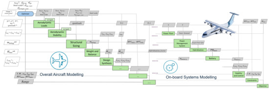
The Multi-disciplinary Design Optimisation (MDO) problem uses a multi-disciplinary Feasible Formulation (MDF), ensuring the coupled system is solved at every iteration to maintain design feasibility. A dedicated ontology links aircraft components, properties, and design variables to disciplines, enabling their instantiation into the MDO framework (see Figure 2).
Figure 2.
Simplified Extended Design Structural Matrix (XDSM) representation of the design problem.
The optimisation employs an objective function to minimize performance metrics (e.g., weight, drag). The constraints can cover limits on structural loads, stability margins, and control deflections. The framework integrates systems modelling (power supply like battery and fuel cell) alongside aero-structural and stability disciplines. This holistic approach drives flying performance and system sizing by providing mass and volume based on power demand, optimising the overall efficiency of the design.
Integrating systems modelling into the MDO framework allows the process to account for the dynamic interactions between aircraft systems (e.g., power delivery and thermal management) and overall performance, ensuring compliance with given requirements. To streamline the optimisation, several simplifications are made: the mass of the fuel cell and engines is constant, and the Environmental Control System (ECS) and Ice Protection System (IPS) are pre-sized. The wing is treated as rigid for structural optimisation, and the analysis is performed at a single flight point considering maximum gravitational loads ( and ). In the first instance, we neglect dynamic loads, excluding gust and continuous turbulence-based loads. For energy considerations, the battery and fuel cell are assumed to operate at nominal conditions. Furthermore, a fixed of the total energy consumption is added to account for the energy used during the climb and descent phases, simplifying the real-world energy usage complexity [6].
3.2. Optimisation Scenario
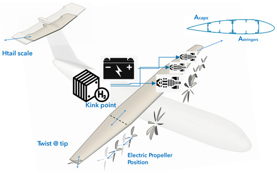
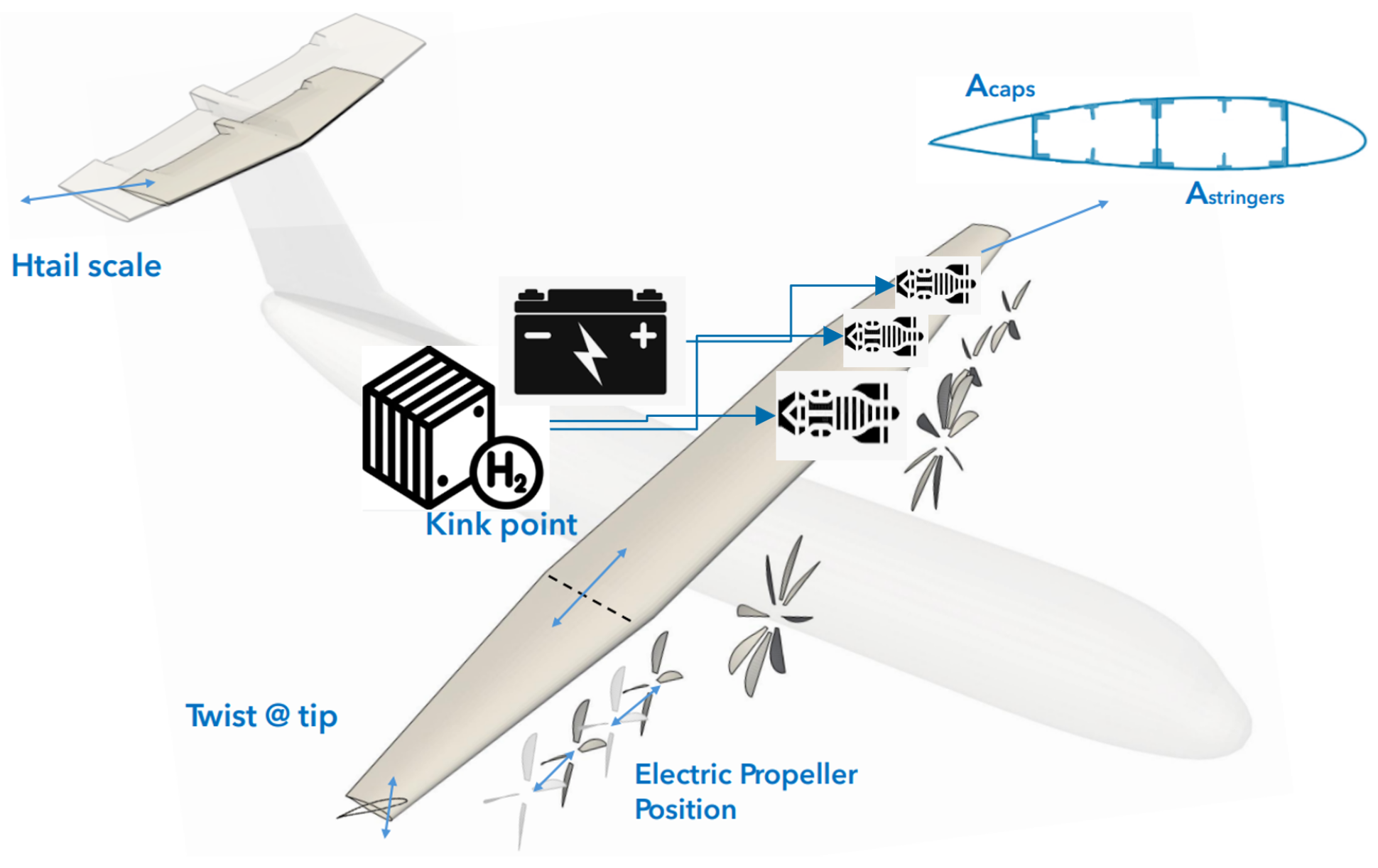
In this MDO problem, we consider the following design variables (see Figure 3):
Figure 3.
Representation of the design variables.
- the kink position of the wing;
- the twist of the tip section of the wing;
- the area of the stringer and roots caps;
- the scale of the tail plane;
- the position of the propellers driven by the electric engine;
- the hybridisation factor between thermal and electric engines (power split);
- the hybridisation factor between the battery and the fuel cell (electric power hybridisation).
For the battery, we need also to prescribe the voltage and the capacity to have it uniquely defined.
With the chosen design variables, we trigger trade-offs between performance and structure [3,6,7]. The kink position of the wing affects aerodynamics (lift and drag) and structural loads (bending, shear) as well as weight distribution. The wing tip twist affects the induced drag and impacts torsional loads.
On the structural side, the area of the stringer and that of the root cap dictate primary structural integrity and weight; increasing their size boosts stiffness but adds mass. The horizontal tail plane scale is critical for stability and control, but larger tails increase drag and weight. Finally, the position of the electric propellers along the wing impacts both the lift-to-drag ratio and the structural bending moments from the engine weight, affecting local flow and propeller–wing interaction. A holistic, integrated approach across all disciplines—flight control, aerodynamics, propulsion, and structure—is essential to meet the stability, frequency, and damping constraints associated with the flight mechanical behaviour of the aircraft. In this study, constraints are mainly associated with the handling qualities of the aircraft and are defined as follows:
- static stability margins between 5% and 35%;
- frequency of the short period between 2.3 rad/s and 3.5 rad/s;
- damping of the short period mode between 0.2 and 1.4;
- damping of the phugoid mode > 0.04.
Note that only inequality constraints are defined. The flight control system is crucial for maintaining stability margins and influencing the frequency and damping characteristics of short-period and phugoid modes. However, control laws, including gain scheduling and feedback mechanisms, can significantly impact these parameters. Stability augmentation and fly-by-wire systems can also enhance damping and adjust frequency characteristics to meet desired constraints, ensuring aircraft stability and responsiveness under various conditions.
The primary objective is to optimize the aircraft’s range. The range equation for a hybrid-electric distributed propulsion regional aircraft must account for unique aspects such as energy management, distributed propulsion, electric motor efficiency, battery characteristics, thermal management, and weight. By addressing these factors, range equations that capture the complexities of hybrid-electric systems and optimize aircraft performance can be formulated [8,9]:
We simplify this equation, recurring to an implicit formulation and reducing it to a more conventional Breguet-like formula:
This is obtained assuming that the payload is fixed. The efficiencies of the different on-board systems are used to further determine the propulsive and nonpropulsive efficiency. In addition, the battery is sized to be fully used during the reference mission, being the maximum take-off weight fixed by the requirements. For simplicity, we assume that the empty weight fraction is equal to 1. Therefore, the zero-fuel weight is the reference empty weight, and it is affected by the different sizes of the battery, as well as its weight, which is part of the design optimisation loop. We disregard the sensitivities of the weight changes to the nominal power demand of the fuel cells. Optimisation is performed at a single point corresponding to the cruise condition, and viscous drag is considered constant.
4. Analysis and Optimisation
In this section, we present the results of the MDO loop. The results shown are non-dimensional with respect to the nominal baseline values. The optimisation process is performed in two distinct steps to ensure a comprehensive and efficient design exploration: (i) initial trimming of the configuration: the configuration is trimmed based on a nominal pre-sized configuration; (ii) MDO Scenario Execution: this step focuses on optimising the design variables that influence the aircraft’s performance. The exclusion of trim variables ensures that the optimisation process is simplified in that at every optimised feasible point, the configuration is not trimmed again. The trimming is performed at the end of the optimisation loop. The trim variables used are the angle of attack, the propeller pitch and the elevator angle. For the optimisation, we use a gradient-free approach based on the Constrained Optimisation BY Linear Approximation (COBYLA) algorithm.
4.1. Convergence and Feasibility
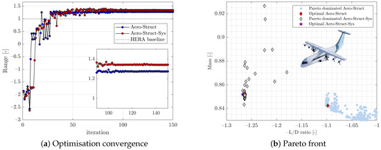
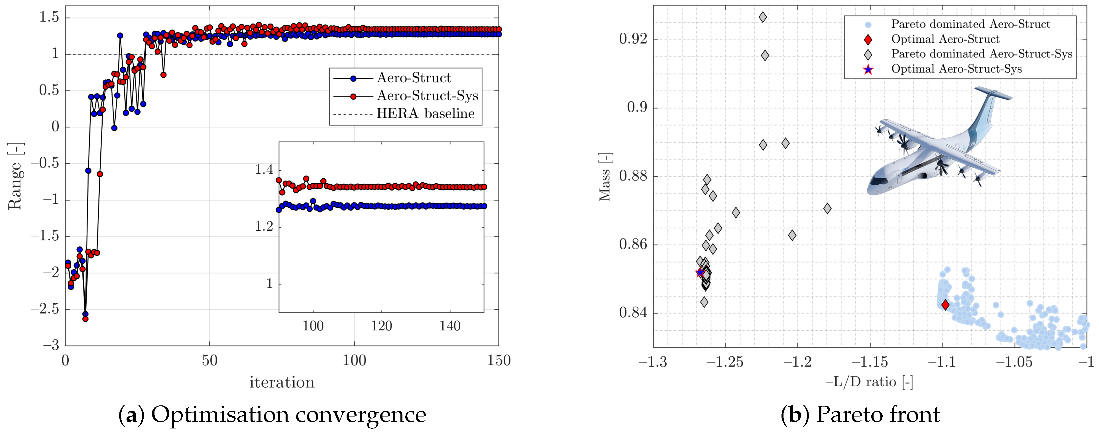
The definition of the surrogate and the approach used for the trimming, as well as the corresponding results, have been determined using the same approach indicated by Granata et al. [2]. The objective function, i.e., the range, converges in approximately 100 iterations (see Figure 4). The final value of the objective function is about 25% higher than the baseline design, indicating a significant improvement in performance compared to the baseline. By explicitly modelling the aircraft’s systems and integrating them into the MDO loop, an additional 7% improvement is achieved. This highlights the importance of considering systems performance in the optimisation process.
Figure 4.
Convergence of the optimisation and pareto front of mass and aerodynamic efficiency.
The pareto front, as shown in (see Figure 4), provides a visual comparison of the solutions obtained by optimising the aircraft with and without the inclusion of systems in the MDO loop. The introduction of systems modelling shifts the area where local minima are found, primarily due to the increased complexity of the design space. This shift underscores the impact of systems performance on the overall optimisation process and the importance of considering these factors in the design process from the early stages.
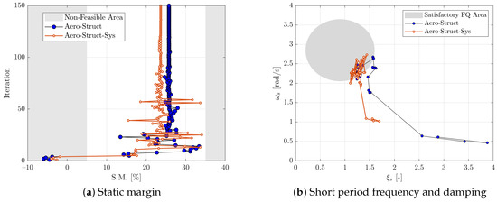
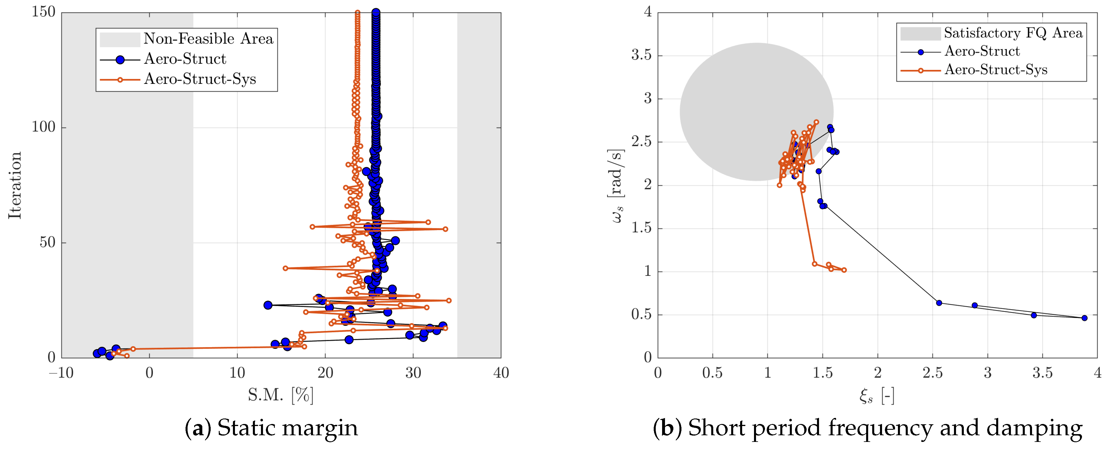
The optimisation process includes constraints to maintain aircraft handling qualities and stability margin. Handling qualities are the characteristics determining the effective aircraft dynamic behaviour, relying on stability, maneuverability, and responsiveness, and influenced by aerodynamics, control surfaces, and mass distribution. The scale of the tail plane is a critical driver for these constraints, as it ensures longitudinal stability by counteracting pitching moments. The stability margin, measured by the static tendency to return to attitude, is also constrained. Both the handling quality and stability margin constraints are fulfilled rapidly—within a few iterations—due to the direct relationship between the tail plane’s scale and the aircraft’s stability and control characteristics (see Figure 5). Adjusting the tailplane allows the optimisation to quickly achieve the desired levels of responsiveness. As expected, the stability margin of an aircraft is influenced by several factors, including its aerodynamic characteristics, centre of gravity (CG) location, and control surface effectiveness.
Figure 5.
Constraints on stability margin and handling qualities.
4.2. Sensitivity Analysis and Optimised Configuration
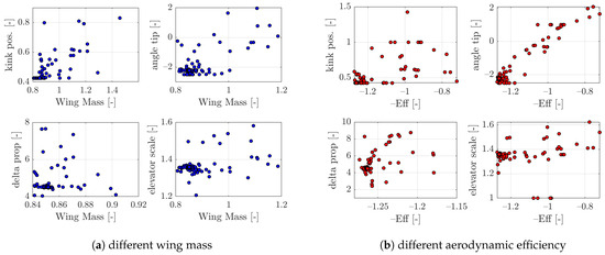
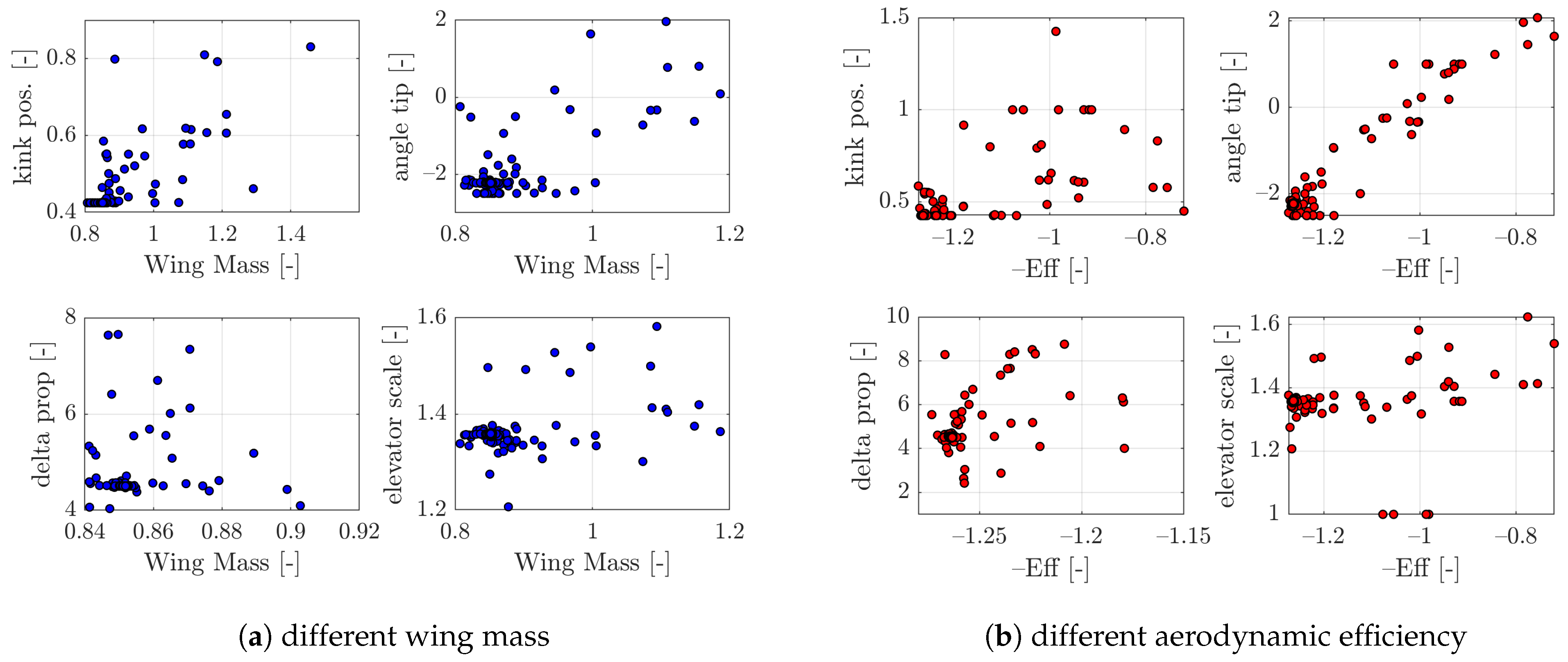
Figure 6 shows the sensitivities of the mass and the aerodynamic efficiency to some geometrical design parameters. For these sensitivities, the covariance coefficient R is always below 0.8, except for the case of the correlation of the wing mass to the king position, where it is equal to 0.93. Similarly, in the case of the aerodynamics efficiency, R is equal to 0.97 and 0.92 respectively for the tip angle and the delta position between the propellers. The use of sensitivity analysis and visual graphics provides valuable insights into the relationships between design variables and performance metrics. We show that the driving factor for mass variations in the aircraft design is the kink position.
Figure 6.
Sensitivity of mass and aerodynamic efficiency to geometrical design variables.
The kink position refers to the location along the wing span where the local sweep angle of the wing changes. This position has a significant effect on the loads distribution and the size of the primary inner structure, which carries most of the loads. The kink position influences the distribution of aerodynamic loads along the wing span. By optimising the kink position, the design can reduce peak loads and distribute them more evenly, leading to a more efficient structural design. This, in turn, reduces the mass of the primary inner structure.
On the other end, the angle of the tip section of the wing directly affects the spanwise lift distribution. This quantity is a critical factor in determining the wing’s overall aerodynamic performance. In fact, the tip angle influences the intensity of the wingtip vortices, which are responsible for the induced drag. By optimizing the tip angle, the design can reduce the strength of these vortices, leading to a reduction in induced drag and an improvement in aerodynamic efficiency.
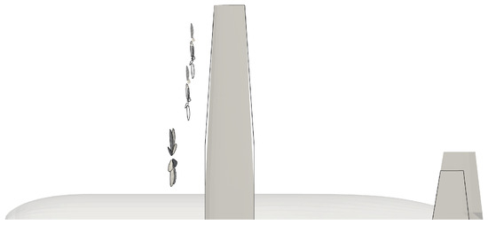
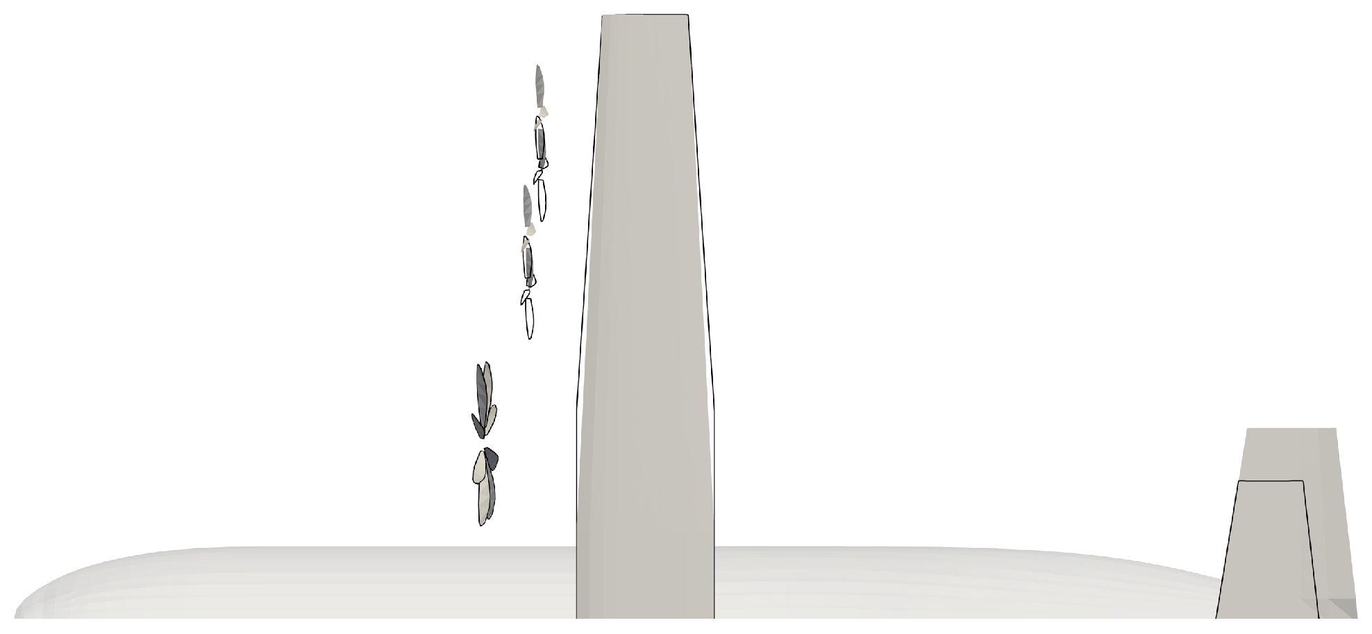
The optimized aircraft configuration (see Figure 7) resulting from a comprehensive multi-disciplinary design and optimisation (MDO) process features several key adjustments that collectively boost performance and efficiency. The angle of the wing tip section position was increased by 5 deg, enhancing the lift-to-drag ratio and reducing induced drag by mitigating wingtip vortices. Concurrently, the propellers were shifted outward by along the span. This placement optimizes propeller–wing interaction. Structurally, the kink position along the wing span was reduced by . This significant change optimizes load distribution and allows for a smaller, lighter inner structure, addressing a critical finding from the sensitivity analysis on mass variation. To improve handling qualities, the elevator size was nearly doubled, significantly enhancing longitudinal stability, which is essential for meeting specified stability margin constraints. This highlights the substantial value of a holistic approach, where complex interactions between systems, aerodynamics, and structure are explicitly modeled and optimized together, resulting in a more efficient and comprehensive final design (see Figure 7).
Figure 7.
Optimised configuration: (shaded) optimised; (black line) baseline.
5. Conclusions
In this study, we conducted a comprehensive Multi-disciplinary Design Optimisation (MDO) process for the HERA UCB distributed propulsion configuration, focusing on improving performance, efficiency, and handling qualities. The key findings are as follows: the kink position was identified as the driving factor for mass variations, influencing loads distribution and the size of the primary inner structure. The tip section angle of the wing was found to be the critical variable for aerodynamic efficiency, affecting lift and drag characteristics and wingtip vortices. The tip section was increased by 5 degrees compared to the baseline, enhancing aerodynamic efficiency. The electric propellers were shifted outward by 5% along the wing span, improving thrust distribution and propeller efficiency. The kink position was reduced by 50% compared to the baseline, optimising loads distribution and structural efficiency, while the elevator size was almost doubled, enhancing longitudinal stability and control authority.
The Constraints on handling qualities and the stability margin were fulfilled within 100 iterations, with handling qualities constraints converging within a few iterations due to the direct relationship with the tailplane scale. The inclusion of systems modelling in the design optimisation process resulted in an additional 7% increase in range, highlighting the importance of a holistic approach to aircraft design, including concurrent sizing of the on-board systems.
Author Contributions
Conceptualization, S.M.; methodology, S.M.; software, S.M.; validation, J.-C.G. and T.K.; formal analysis, S.M.; investigation, S.M.; resources, S.M., T.K., S.B. and J.-C.G.; data curation, S.M. and T.K.; writing—original draft preparation, S.M.; writing—review and editing, S.M. and R.M.; visualization, S.M.; supervision, J.-C.G.; project administration, T.K. and Ö.P. All authors have read and agreed to the published version of the manuscript.
Funding
This research was co-funded by the European Union under GA no. 101140510. Views and opinions expressed are however those of the authors only and do not necessarily reflect those of the European Union or Clean Aviation Joint Undertaking. Neither the European Union nor the granting authority can be held responsible for them.
Institutional Review Board Statement
Not applicable.
Informed Consent Statement
Not applicable.
Data Availability Statement
The raw data supporting the conclusions of this article will be made available by the authors on request.
Acknowledgments
The authors thank Sven Lanzan Ferran from Airbus Defence and Space for the feedback and the constructive inputs to the discussions around the multidisciplinary design framework.
Conflicts of Interest
Authors Simone Mancini, Tim Klaproth, Reinhold Maierl, and Ögmundur Petersson were employed by the company Airbus Defence and Space GmbH. The remaining authors declare that the research was conducted in the absence of any commercial or financial relationships that could be construed as a potential conflict of interest.
Abbreviations
The following abbreviations are used in this manuscript:
| Gas turbine (thermal engine) efficiency | |
| Electrical bus/system efficiency | |
| Propulsive efficiency | |
| Lift-to-drag ratio | |
| Degree of hybridisation (power split ratio) | |
| Specific energy of the fuel (J/kg) | |
| g | Gravitational acceleration () |
| Range of the parallel hybrid aircraft (m) | |
| Range (m) | |
| R | Covariance coefficient |
| Operating empty weight (N) | |
| Payload weight (N) | |
| Total initial energy available (J) | |
| Specific energy of the battery (J/kg) | |
| Electric motor efficiency |
References
- Clean Aviation Joint Undertaking. Hybrid-Electric Regional Architecture (HERA). CORDIS—EU Research Results. Grant Agreement No. 101102007. 2022, Start Date: 1 January 2023. Available online: https://cordis.europa.eu/project/id/101102007 (accessed on 5 February 2025).
- Granata, D.; Mancini, S.; Mateo-Gabin, A.; Zanotti, A. Enhancing a Distributed Electric Propulsion Configuration Aircraft Design with a Multidisciplinary Analysis and Optimization Approach. In Proceedings of the 51st European Rotorcraft Forum (ERF 2025), Venice, Italy, 9–12 September 2025. [Google Scholar]
- Mateo-Gabín, A.; Mancini, S.; Martín, M.A.; Fernández Montes, J.; Lanzan Ferran, S.A.; Klaproth, T. An AI-enhanced multidisciplinary optimization framework for net-zero transport aircraft. In Proceedings of the AIAA Aviation Forum and ASCEND 2025, Las Vegas, NE, USA, 21–25 July 2025; pp. 1–18. [Google Scholar]
- GEMSEO Documentation. GEMSEO: Generic Engine for Multi-Disciplinary Scenarios, Exploration, and Optimization. Available online: https://gemseo.readthedocs.io/en/stable/index.html# (accessed on 10 March 2024).
- DLR. CPACS. Available online: https://dlr-sl.github.io/cpacs-website (accessed on 20 July 2024).
- Adler, E.; Martins, J. Aerostructural wing design optimization considering full mission analysis. In Proceedings of the AIAA Aviation Forum and ASCEND 2022, San Diego, CA, USA, 3–7 January 2022. [Google Scholar] [CrossRef] [Scilit]
- Fang, J.; Sun, G.; Qiu, N.; Kim, N.H.; Li, Q. On design optimization for structural crashworthiness and its state of the art. Struct. Multidiscip. Optim. 2017, 55, 1091–1119. [Google Scholar] [CrossRef] [Scilit]
- Batra, A.; Raute, R.; Camilleri, R. On the Range Equation for Hybrid-Electric Aircraft. Aerospace 2023, 10, 687. [Google Scholar] [CrossRef] [Scilit]
- Palaia, G.; Abu Salem, K. Mission Performance Analysis of Hybrid-Electric Regional Aircraft. Aerospace 2023, 10, 246. [Google Scholar] [CrossRef] [Scilit]
Disclaimer/Publisher’s Note: The statements, opinions and data contained in all publications are solely those of the individual author(s) and contributor(s) and not of MDPI and/or the editor(s). MDPI and/or the editor(s) disclaim responsibility for any injury to people or property resulting from any ideas, methods, instructions or products referred to in the content. |
© 2026 by the authors. Licensee MDPI, Basel, Switzerland. This article is an open access article distributed under the terms and conditions of the Creative Commons Attribution (CC BY) license.