Skip to Content
  • Proceeding Paper
  • Open Access

26 May 2026

Proof of Concept of Radars for UAM/IAM Applications †
,
and
ITACA Research Institute, Universitat Politècnica de València, 46022 Valencia, Spain
*
Author to whom correspondence should be addressed.
Presented at the 15th EASN International Conference, Madrid, Spain, 14–17 October 2025.

Abstract

The increasing use of Unmanned Aerial Systems (UAS) in civil applications has accelerated the development of new Air Traffic Management (ATM) frameworks to ensure the safe and efficient operation. Onboard technology, such as Detect and Avoid (DAA) systems, have been proposed as an alternative to reduce operational risk to acceptable levels. However, these technologies require preliminary validation to meet current regulatory standards, which define the Minimum Operational Performance (MOP). In this work, we propose the architecture of two DAA systems based on frequency-modulated continuous-wave (FMCW) radars operating in the radiolocalization bands at 9.5 GHz and 24 GHz. The performance of both onboard systems was validated through the probability of detection P d for different intruder categories, meeting the MOP in accordance with the RTCA DO-366A, DO-396, and ASTM F3442 standards.

1. Introduction

Unmanned Aircraft Systems (UAS) have emerged as key enablers of modern Innovative Aerial Mobility (IAM) and Urban Air Mobility (UAM), offering new capabilities for transportation, last-mile delivery, surveillance, and infrastructure inspection services within populated environments. In this context, the global UAS market was valued at approximately USD 530.2 million in 2022 and is projected to expand at a compound annual growth rate of 42.6% between 2023 and 2030 [1]. The increasing adoption of UAS technology has driven the development of new airspace regulations, particularly for very low-level (VLL) operations below 400 ft, as traditional civil Air Traffic Management (ATM) systems are not capable of supporting scalable UAS operations. Therefore, this limitation has driven academic and industrial initiatives to integrate these services into civil airspace. U-space is the European program to manage UAS traffic under a set of specific services and procedures designed to ensure safe and efficient operations [2]. Several services, such as digital registration, flight authorization, traffic information and network identification have been developed in the early stages of U-space. However, emergency management and conflict resolution between aircraft are still considered critical challenges to address. Depending on the type of operation, UAS operators must integrate specific mitigation strategies to reduce air and ground risk to acceptable levels, such as the incorporation of onboard mitigation subsystems to ensure safety.
Detect and Avoid (DAA) systems are solutions for tactical conflict resolution by current regulatory frameworks within a U-space context. On one hand, the Radio Technical Commission for Aeronautics (RTCA) has published the DO-396 standard, which defines the Minimum Operational Performance Standard (MOPS) for the Airborne Collision Avoidance System for Small Unmanned Aircraft (ACAS sXu) with a wingspan shorter than 25 ft [3]. In addition, DO-396A recognizes Air-to-Air Radar (ATAR) as a key enabling technology for DAA systems. For this reason, the DO-366A establishes the MOP of ATAR for Traffic Surveillance, defining intruder categories based on the Radar Cross Section (RCS) of UAVs [4]. On the other hand, the American Society for Testing and Materials (ASTM) proposes the F3442/F3442M-23 standard for DAA systems performance requirements [5], as well as the operational boundary volumes (Well Clear Boundary, or WCB) based on a risk index. This volume must be monitored by the onboard DAA systems to ensure safe operations.
In this context, DAA systems must deal with both cooperative and non-cooperative intruders. Radar systems, LiDAR, and infrared cameras stand out as strong candidates for detecting non-cooperative UAS due to their level of technological maturity. Recent studies have proposed architectures, algorithms, and components aimed at the development of onboard radars [6,7,8]. However, within a U-space context, DAA systems must ensure both feasibility and reliable operation, considering the minimum operational performance. This work presents two proof-of-concept FMCW radar-based DAA systems in the X and K bands, developed in accordance with DO-396, DO-366, and F3442 standards. The architectures combine commercial components with tailored monopulse antennas for a compact and integrable solution.

2. Materials and Methods

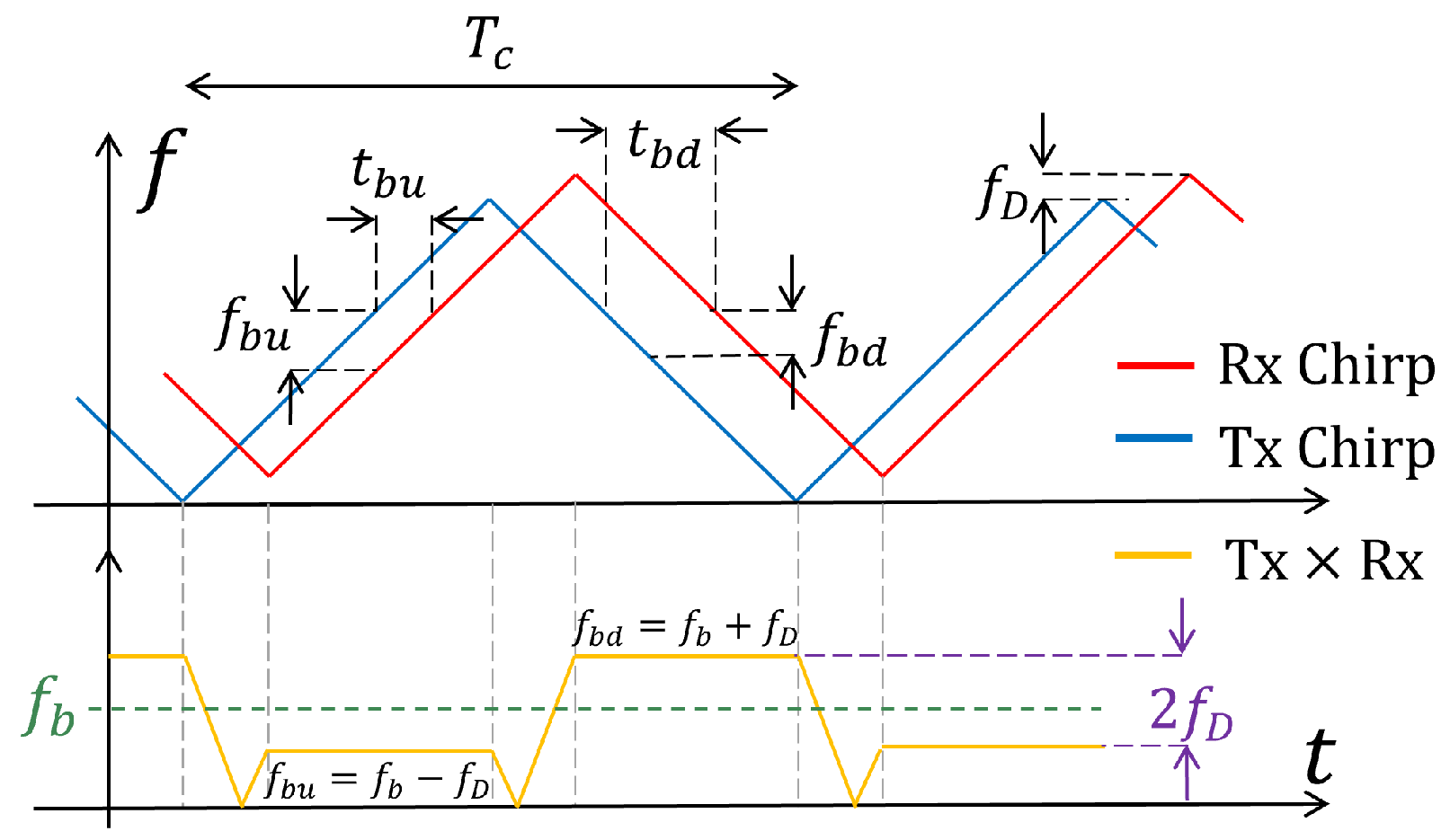
Continuous-wave (CW) radar transmits signals with linear frequency modulation (LFM or chirp) to estimate both range and radial speed of targets. Particularly for FMCW radars, the instantaneous frequency changes periodically with triangular, sawtooth, and sinusoidal waveform shapes [9]. Autonomous navigation systems commonly transmit sawtooth and triangular modulations [10], which allow the simultaneous estimation of both distance and velocity within a single observation. A triangular LFM signal changes its frequency f T ( t ) linearly over time within a fixed bandwidth BW, switching from a positive slope during the first half of T c to a negative slope during the second half. Figure 1 illustrates the time and frequency-domain response of a transmitted chirp, as well as the received signal caused by a moving target.
Figure 1. Triangular LFM signal and received time and frequency-shifted replica caused by a moving target.
This echo represents a copy with a time and frequency shift related to the target’s characteristics. The product of the transmitted and received signals (yellow line in Figure 1) contains a primary frequency component f b , with periodic variations ±   f D , corresponding to the target’s distance R and radial velocity v r , respectively. Chirp parameters are selected to satisfy the radar performance requirements, including the maximum unambiguous range and velocity, as well as the desired range and velocity resolutions. The synthesis equations of these parameters are well-known expressions in the literature [10,11]. In particular, for a FMCW system with a triangular LFM signal, the expressions are summarized as follows:
R max = c T c 2 , Δ R = c 4 BW ,
v r max = λ 4 T c , Δ v r = λ 2 T c n P ,
where λ is the wavelength, c the speed of light, and n P the number of chirps transmitted during the acquisition time. Target parameters are obtained by multiplying the n P sampled transmitted and received chirps, producing a ( n P × n s ) matrix, where n s is the number of samples per chirp. Fast Fourier Transform (FFT), applied along the rows, yields the range spectrum by extracting the delays introduced by the targets. The phase variation between consecutive chirps exhibits a periodic pattern associated with the Doppler shift. Therefore, a second FFT is applied across the columns to estimate f D [10,11]. This two-dimensional processing produces the range–Doppler map, where each cell corresponds to the reflected power from a target at range R and radial velocity v r .
The detection probability P d is a key radar performance parameter, representing the probability of detecting a target when it is present, while the probability of false alarm P f a is the probability of declaring a target when it is not present. At the system level, the capabilities of radar systems are defined in terms of P d for a particular signal-to-noise ratio (SNR) and an acceptable P f a . The definition of the detection probability P d depends strongly on the type of radar. In particular, for FMCW radars using FFT processing, P d is expressed as [12]:
P d = exp log ( P f a ) 1 + n s SNR .
As shown, this expression is independent of the noise power and is a function of the SNR, the size of the FFT per chirp n s , and the false alarm probability of the detector.

2.1. X-Band Radar Architecture

The first proposed architecture operates within the X-band with a center frequency of 9.5 GHz, within the designated band for airborne radiolocation systems according to the ITU [13]. Regarding the radiating element, this system integrates a rescaled version of the monopulse antenna proposed in [7] to operate within the X-band. The element consists of an array of sixteen horn antennas, four of which are used as a preliminary validation stage of the system. We propose a superheterodyne architecture with two transmitters and receivers connected to a software-defined radio (SDR) platform.
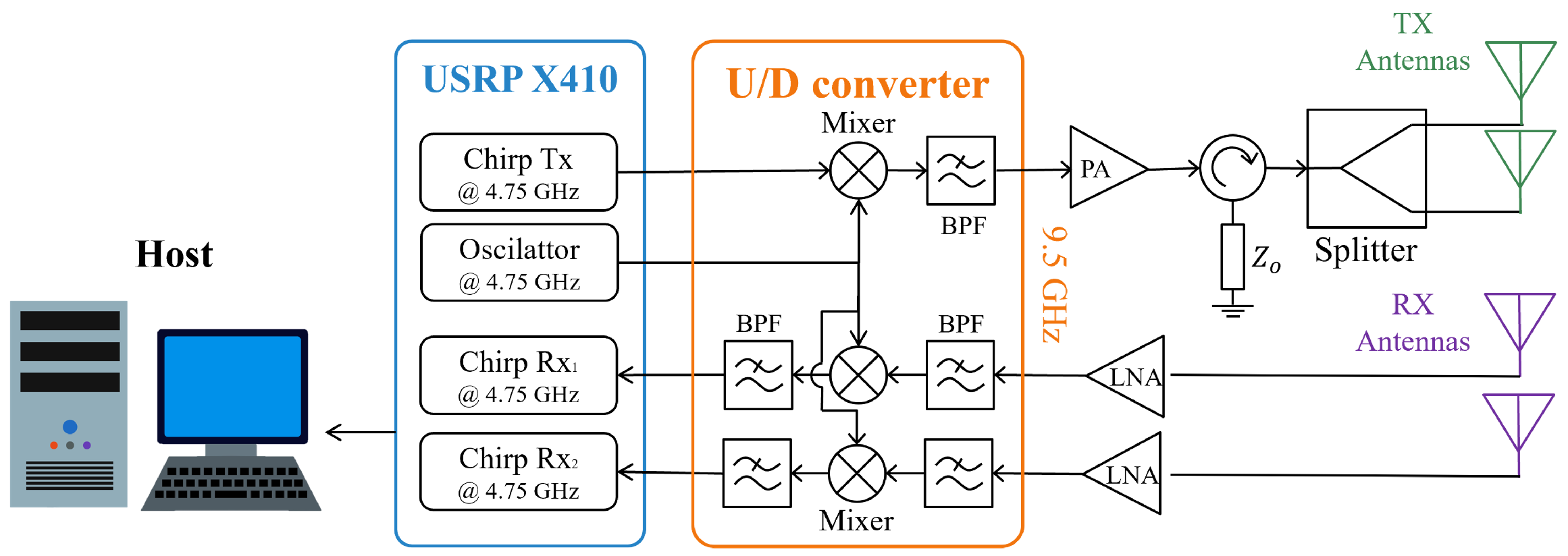
Figure 2 shows the system architecture. The Up/Down Converter is tailored for X-band operation to overcome the USRP X410 frequency limitations. Two transmitter channels are used: one generates the frequency-modulated pulse train, while the other provides the local oscillator (LO). Both in-phase 4.75 GHz signals are mixed, producing sum and difference spectral components. A band-pass filter then isolates the 2 f L O component for transmission. In this design, three MT3H-0113LSM triple-balanced passive diode mixers from Marki Microwave® (Morgan Hill, CA, USA) are integrated. The up-converted signal propagates through a 7 W PE15A5044 power amplifier (PA) followed by a single-junction PE8403 circulator, both fabricated by Pasternack® (Irvine, CA, USA). The resulting output is subsequently split by a ZN2PD-02183+ divider to feed the two transmitter cavities of the antenna.
Figure 2. X-band radar system architecture.
Both receivers use a low-noise amplifier (LNA) followed by a band-pass filter to suppress adjacent-channel interference. The signal is amplified by 20 dB using theMini-Circuits ZX60-06183 LNA, (Brooklyn, NY, USA) filtered, and mixed with the f L O carrier. After filtering, the 4.75 GHz intermediate frequency, the signal is connected to the USRP receiver channels for sampling and processing.

2.2. K-Band Radar

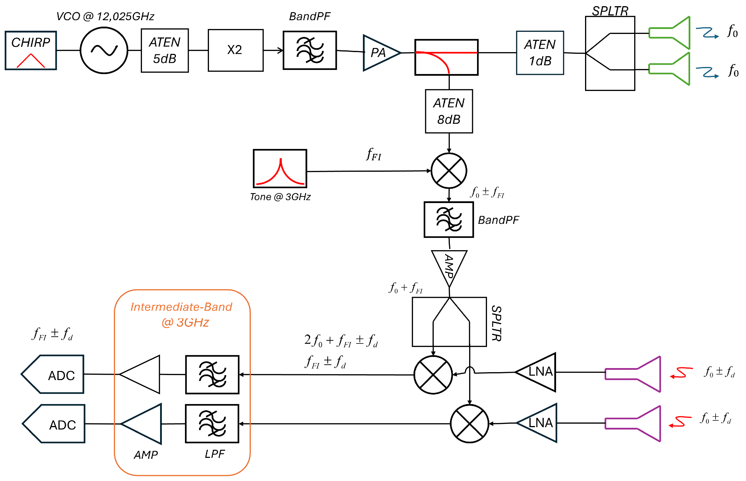
The second architecture proposed is a K-band radar operating at the 24.05–24.25 GHz band recommended for radiolocation systems according to the ITU [14]. Figure 3 details the superheterodyne architecture with two transmitters and two receivers connected to four cavities of the monopulse sectorial antenna proposed in [7]. The transmit signal is generated using a local oscillator (LO) and a frequency doubler, followed by an Analog Devices ADPA7007CHIP PA (Wilmington, MA, USA) and a splitter to feed the two antenna cavities.
Figure 3. K-band radar system architecture.
On the receiver side, we used the GNA-700F LNA and a conventional superheterodyne topology that down-converts the received signal to a 3 GHz intermediate frequency (IF) by mixing it with a shifted sample of the transmitted signal. The mixing stage was implemented using the HMC292ALC3B mixer from Analog Devices. The sampling frequency is fixed at 60 MHz to improve detection capabilities and resolution.

2.3. Minimum Operational Performance for DAA Systems

Table 1 summarizes the minimum operational requirements for DAA systems, defined according to the RTCA DO-366A, DO-396, and ASTM F3442/F3442M standards. The RTCA establishes three groups of intruders: small, medium, and large, based on their RCS and maximum velocity. Although DAA systems commonly assume a human as the minimum detectable object, the growing use of sUAV has increased the need to characterize their RCS. Reported measurements indicate that small drones generally exhibit RCS values in the range of 20 to 9 dBsm in both the X and K bands. Refs. [15,16,17], motivating the adjustment of minimum-detectable target requirements.
Table 1. Minimum operational capabilities for DAA systems based on the RCS of multiple intruders, the definition of their WCB and maximum speed.
Both proposed systems must unambiguously detect targets positioned at the limits of the WCB, defined as cylindrical safety volumes surrounding the UAV that must be free of intruders [3,5]. In this context, the system must detect a large UAV with a RCS greater than 10 dBsm at 1524 m, as well as a commercial drone at 60.96 m. Regarding maximum detectable velocity, the DO-366A standard states that the velocity of large targets must not exceed 314.84 km/h. Under these conditions, the chirp parameters, radar performance, and acquisition parameters proposed to meet these requirements are summarized in Table 2, Table 3, and Table 4, respectively.
Table 2. Chirp parameters.
Table 3. Radar performance.
Table 4. Acquisition parameters.

3. Results

Numerical Validation of the Minimum Operational Performance Standards

System simulations are carried out in AWR Cadence, where the frequency response of commercial components is included along with propagation losses, delay, and the Doppler effect experienced by the transmitted chirp. The simulator also enables modeling of intruders through their RCS, Swerling fluctuation models, distance, and speed, as well as clutter and jamming interference. In this context, we evaluate the detection probability to determine the system’s range and verification of the required maximum range for each category. The RF budget analysis of AWR evaluates the variation of the SNR given an intruder with a fixed radial velocity v r at a distance R relative to the radar.
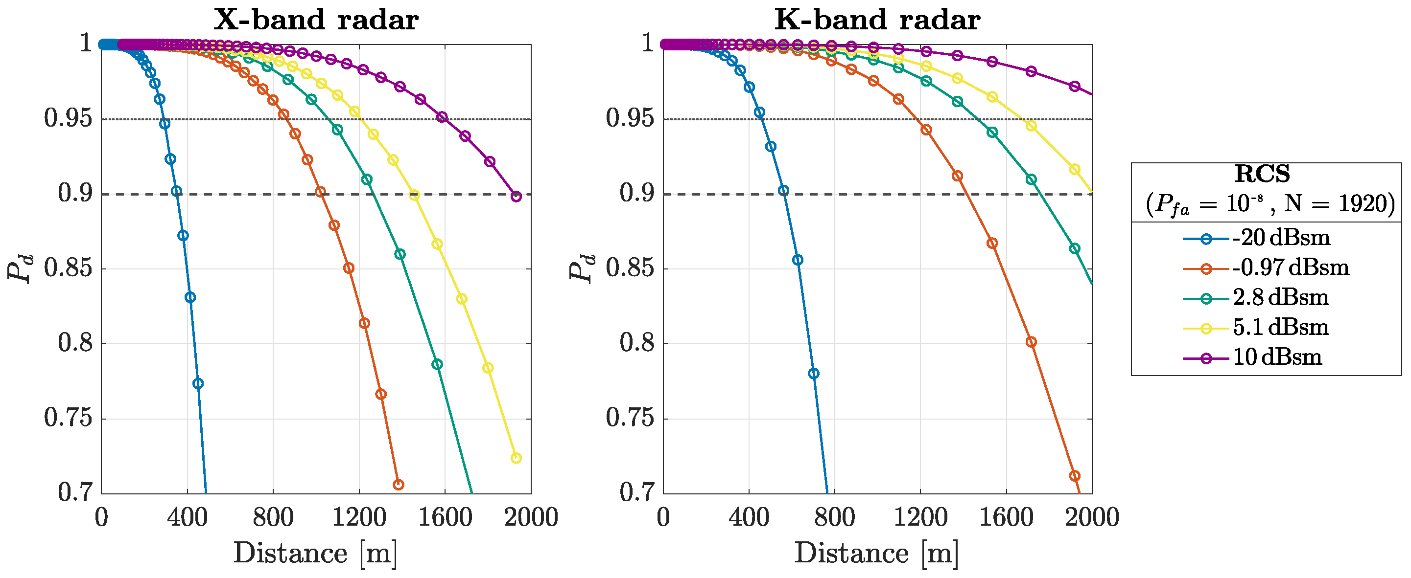
The relationship between the target-to-radar distance and the detection probability (3) is shown in Figure 4. We consider a fixed P f a = 10 8 of a Constant False Alarm Rate (CFAR) detector. As shown, both systems ensure an adequate P d given a low SNR, since the number of samples per chirp n s is 1920. We define the maximum detectable range of the system as the distance for which P d exceeds 95 % .
Figure 4. Probability of detection as function of distance to the target, considering a Swerling I model of RCS for each category.
Table 5 summarizes the capabilities of the proposed DAA system for each target category established by the RTCA DO-366A standard. According to the results, the system meets the minimum operational performance requirements and is therefore considered a viable prototype.
Table 5. Proposed radar performance based on probability of detection.
The range-Doppler matrix is computed from the samples generated in simulation, considering two intruders defined by the Swerling I model RCS. The magnitude of the resulting spectrum passes through a CFAR detector with a false alarm probability of 10 8 , determining the estimated position and velocity of the targets. Considering the X-band acquisition parameters, the average Python 2026 processing time is 690 ms on an Intel® Core i5-14400F with 32 GB RAM. Applying the same procedure to the K-band system yields an average processing time of 1.34 s.
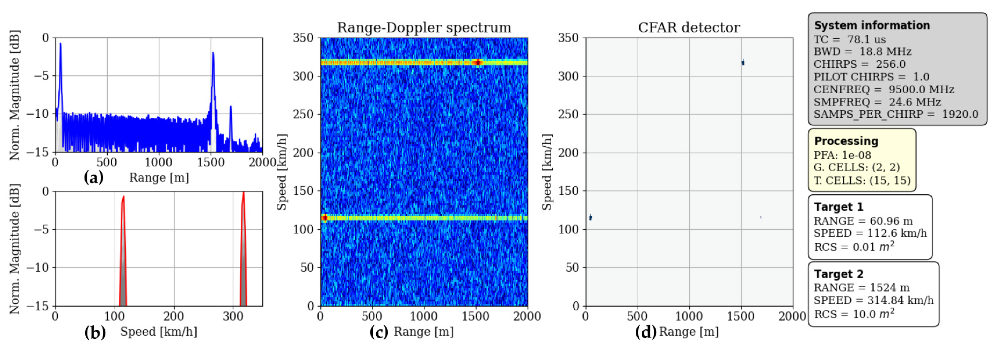
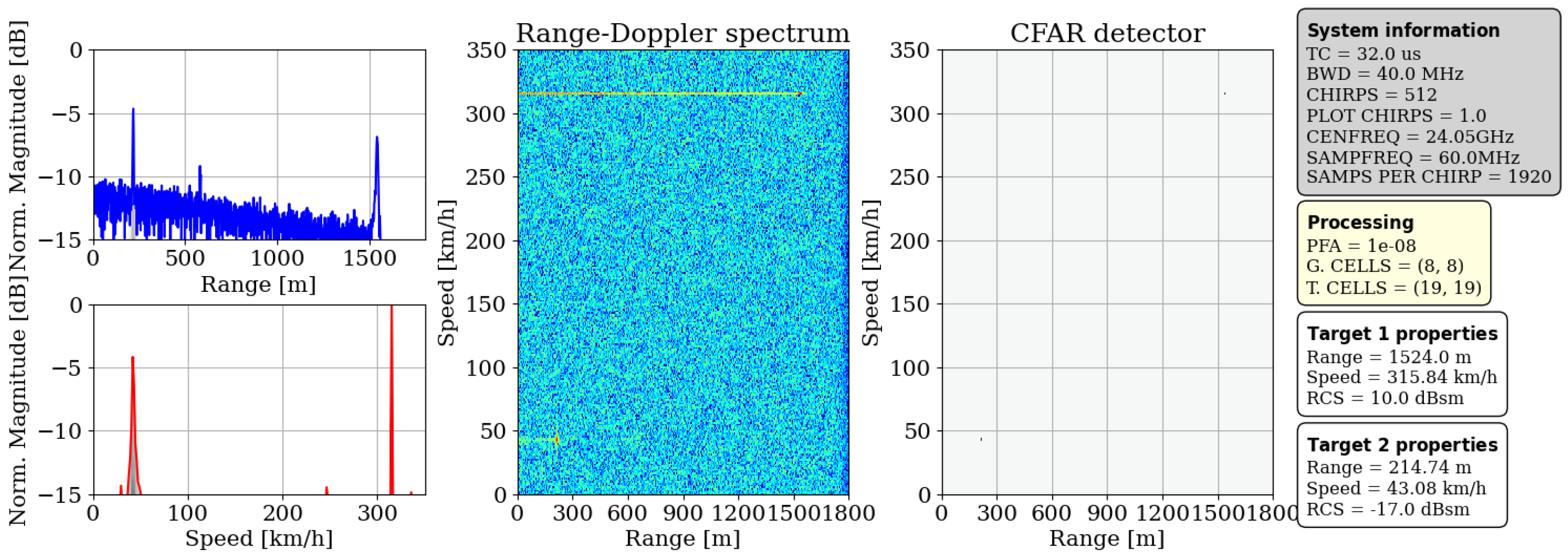
A two-target scenario was simulated with both objects located at the WCB boundaries, while one target exceeded the 314.84 km/h velocity limit to assess performance under critical conditions. Figure 5 and Figure 6 illustrate the results of the normalized magnitude of the Range–Doppler matrix, and the maximum along each axis is computed for both X-band and K-band radars, respectively. The output of the CFAR detector is presented on the right side of the figures.
Figure 5. X-band range and velocity estimation for two targets: maximum along (a) range axis and (b) speed axis, (c) range–Doppler map (considering Hamming window. Red means higher intensity than blue), and (d) CFAR output.
Figure 6. K-band range and velocity estimation for two targets. (Red means higher intensity than blue).
From the results, it can be observed that both intruders are distinguished, exhibiting a peak-to-noise floor ratio of approximately 10 dB for the X-band and 5 dB for the K-band radar. However, side-lobes can be seen along the range axis (an intrinsic characteristic of Range–Doppler processing), which depends on the window function used [10,11] and is significantly reduced by the CFAR detector. It is important to note that the number of guards and training cells was determined through iterative testing of the algorithm.

4. Discussion

Compared with the K-band implementation, the X-band radar exhibits several practical advantages that enhance its suitability for real-time DAA operation. Its shorter processing time enables faster update rates, which is crucial for the detection of nearby intruders. Furthermore, the use of a software-defined radio (SDR) front end provides flexibility, allowing the modification of RF parameters. The required sampling frequency and bandwidth can also be supported by less complex and more affordable equipment, reducing system costs. However, the increased weight and larger overall system size are unsuitable for platforms with strict payload limitations. In contrast, while the K-band system achieves higher range resolution and reduced antenna dimensions, it suffers from longer processing times and higher component costs. Overall, both systems meet the MOPS, but the X-band radar offers superior real-time performance and flexibility, whereas the K-band system provides enhanced resolution in a more compact but costlier configuration.

Author Contributions

Conceptualization, J.V.B.; methodology, J.F.G.-P. and P.C.-E.; software, J.F.G.-P.; validation, J.F.G.-P. and P.C.-E.; formal analysis, J.F.G.-P. and P.C.-E.; investigation, J.F.G.-P. and P.C.-E.; resources, J.V.B.; writing—review and editing, J.F.G.-P., P.C.-E. and J.V.B.; supervision, J.V.B.; funding acquisition, J.V.B. All authors have read and agreed to the published version of the manuscript.

Funding

This research was conducted within the framework of the CREATE U-space project. The CREATE U-space project (CIAICO/2022/044) received funding from the Conselleria de Innovación, Universidades, Ciencia y Sociedad Digital of the Generalitat Valenciana.

Institutional Review Board Statement

Not applicable.

Data Availability Statement

Github repository of the project here: https://github.com/jfgonzalezpar/DAA-FMCW-Radar (accessed on 5 May 2026).

Conflicts of Interest

The authors declare no conflicts of interest.

Abbreviations

The following abbreviations are used in this manuscript:
ASTMAdvancing Standards Transforming Markets
CFARConstant False Alarm Rate
DAADetect and Avoid
FMCWFrequency-Modulated Continuous Wave
IAMInnovative Air Movility
ITUInternational Telecommunication Union
LFMLinear Frequency Modulated
MOPSMinimum Operational Performance Standard
RCSRadar Cross Section
RTCARadio Technical Commission for Aeronautics
sUAVSmall Unmanned Aircraft Vehicle
UAMUrban Air Mobility
UAVUnmanned Aerial Vehicle
WCBWell Clear Boundary

References

  1. Grand View Research. Delivery Drones Market Size, Share & Trends Analysis Report, 2023–2030; Technical Report; Grand View Research: San Francisco, CA, USA, 2022. [Google Scholar]
  2. Undertaking, S.J. CORUS: Concept of Operations for European U-space Services U-space Concept of Operations, 4th ed.; Technical Report; SESAR Joint Undertaking: Brussels, Belgium, 2023. [Google Scholar]
  3. Estándar DO-396; Minimum Operational Performance Standards for Airborne Collision Avoidance System sXu (ACAS sXu). Radio Technical Commission for Aeronautics (RTCA): Washington, DC, USA, 2022.
  4. Estándar DO-366A; Minimum Operational Performance Standards (MOPS) for Air-to-Air Radar for Traffic Surveillance. Radio Technical Commission for Aeronautics (RTCA): Washington, DC, USA, 2020.
  5. Estándar F3442/F3442M-23; Standard Specification for Detect and Avoid System Performance Requirements. ASTM International: West Conshohocken, PA, USA, 2025.
  6. Saponara, S.; Lischi, S.; Massini, R.; Musetti, L.; Staglianò, D.; Berizzi, F.; Neri, B. Low Cost FMCW Radar Design and Implementation for Harbour Surveillance Applications. In Applications in Electronics Pervading Industry, Environment and Society: APPLEPIES 2014; Springer International Publishing: Cham, Switzerland, 2016; pp. 139–144. [Google Scholar] [CrossRef]
  7. Ruiz Alapont, J.; Ferrando-Bataller, M.; Balbastre, J.V. Proof-of-Concept of a Monopulse Antenna Architecture Enabling Radar Sensors in Unmanned Aircraft Collision Avoidance Systems for UAS in U-Space Airspaces. Appl. Sci. 2025, 15, 5618. [Google Scholar] [CrossRef]
  8. Quevedo, A.D.; Urzaiz, F.I.; Menoyo, J.G.; López, A.A. Drone Detection and RCS Measurements with Ubiquitous Radar. In Proceedings of the 2018 International Conference on Radar (RADAR), Brisbane, Australia, 27–31 August 2018; pp. 1–6. [Google Scholar] [CrossRef]
  9. Mahafza, B.R. Radar Systems Analysis and Design Using MATLAB; Taylor & Francis Group, LLC: Boca Raton, FL, USA, 2005. [Google Scholar]
  10. Richards, M.A. Fundamentals of Radar Signal Processing; Mcgraw-Hill: New York, NY, USA, 2005; Volume 1. [Google Scholar]
  11. Levanon, N.; Mozeson, E. Radar Signals, 1st ed.; John Wiley & Sons: Hoboken, NJ, USA, 2004. [Google Scholar] [CrossRef]
  12. Wu, Y.; Linnartz, J. Detection performance improvement of fmcw radar using frequency shift. In Proceedings of the 32nd WIC Symposium on Information Theory in the Benelux, Brussels, Belgium, 10–11 May 2011; pp. 1–8. [Google Scholar]
  13. ITU. Characteristics and Spectrum Considerations for Sense and Avoid Systems use on Unmanned Aircraft Systems; Reporte M.2204; International Communication Union: Geneva, Switzerland, 2011. [Google Scholar]
  14. International Telecommunication Union. Radio Regulations, Edition of 2020: Volume 1, Articles; ITU: Geneva, Switzerland, 2020; pp. 66–178. [Google Scholar]
  15. Sedivy, P.; Nemec, O. Drone RCS Statistical Behaviour; Technical Report STO-MP-MSG-SET-183; Retia, a.s: Pardubice, Czech Republic, 2016. [Google Scholar]
  16. Li, C.J.; Ling, H. An Investigation on the Radar Signatures of Small Consumer Drones. IEEE Antennas Wirel. Propag. Lett. 2017, 16, 649–652. [Google Scholar] [CrossRef]
  17. Semkin, V.; Haarla, J.; Pairon, T.; Slezak, C.; Rangan, S.; Viikari, V.; Oestges, C. Analyzing Radar Cross Section Signatures of Diverse Drone Models at mmWave Frequencies. IEEE Access 2020, 8, 48958–48969. [Google Scholar] [CrossRef]
Disclaimer/Publisher’s Note: The statements, opinions and data contained in all publications are solely those of the individual author(s) and contributor(s) and not of MDPI and/or the editor(s). MDPI and/or the editor(s) disclaim responsibility for any injury to people or property resulting from any ideas, methods, instructions or products referred to in the content.

Article Metrics

Citations

Article Access Statistics

Multiple requests from the same IP address are counted as one view.