Proceeding Paper

Techno-Economic Assessment of Hybrid Renewable Energy Systems for Electric Vehicle Smart Charging (EVSC) in BRT Infrastructure †
by
Ayodeji Akinsoji Okubanjo
1,*,
Ignatius Kema Okakwu
1,
Adekunle Olorunlowo David
2,*,
Julius Musyoka Ndambuki
2,
Jacques Snyman
2,
Williams Kehinde Kupolati
2 and
Mpho Muloiwa
2
1
Department of Electrical and Electronics Engineering, College of Engineering and Environmental Studies, Olabisi Onabanjo University, Ibogun Campus, Ifo 120107, Ogun State, Nigeria
2
Department of Civil Engineering, Tshwane University of Technology, Private Bag X680, Pretoria 0001, South Africa
*
Authors to whom correspondence should be addressed.
Presented at the 34th Southern African Universities Power Engineering Conference (SAUPEC 2026), Durban, South Africa, 30 June–1 July 2026.
Eng. Proc. 2026, 140(1), 32; https://doi.org/10.3390/engproc2026140032
Published: 26 May 2026

Abstract

The electrification of public transport, particularly Bus Rapid Transits (BRT), is a significant step toward achieving sustainable urban mobility and reducing dependency on fossil fuels. However, rapid adoption of Electric Vehicles Smart Charging (EVSC) infrastructure presents grid stability, economic and environmental concerns. The rising demand for electric cars, particularly in developing nations such as Nigeria, highlights the urgent need for a sustainable hybrid renewable energy charging infrastructure for BRT systems. This study presents a techno-economic assessment of an off-grid hybrid systems that use photovoltaic (PV), wind turbines (WTs), hydrogen (H2), fuel cell (FC) and battery technologies to power Electric Vehicles Smart Charging within Bus Rapid Transits networks. The Lagos BRT charging system at City Mall Station (CMS) serves as a case study, with hourly renewable resources obtained from National Aeronautics and Space Administration database (NASA). Using the HOMER pro-optimization tool, a multi-criteria analysis is performed to evaluate system viability, with special focus on key metrics such as levelized cost of energy (LCOE), net present cost (NPC), renewable energy fraction (REF), and greenhouse gas (GHG) emissions. The simulation results demonstrate that the hybrid PV/wind/FC/battery configuration is exceptionally economical, with an LCOE as low as $0.222/kWh, $2.03M NPC, 51.3% REF, and 159,209 kg of carbon dioxide emissions per year compared to grid-dependent charging. The study shows that integrated renewable-hydrogen systems are not only financially feasible, but also provide significant insights for policymakers, transportation authorities, and energy planners seeking to accelerate the transition to green public transportation infrastructure through innovative hybrid energy schemes.

1. Introduction

The rapid urbanization and increasing demand for sustainable mobility have heightened the need to decarbonize public transportation systems. Bus Rapid Transit (BRT) networks, which are popular in urban areas due to their efficiency and scalability, are rapidly adopting electric vehicles (EVs) to minimize carbon footprints and reliance on fossil fuels [1,2]. However, growing EV adoption raises energy and infrastructure issues, notably in meeting high charging demands without overloading the grid. As a result, hybrid renewable energy systems (HREs) comprising solar PV, wind, fuel cells, batteries, and hydrogen storage provide a long-term solution for promoting EVCS infrastructure.
Recent studies [3,4,5,6,7,8] investigated a variety of HREs for EV charging applications, focusing on their ability to minimize operational costs and carbon emissions. For example, a hybrid PV-WT-BAT system was investigated for an off-grid linked EV charging station [9], resulting in increased reliability and lower levelized cost of energy (LCOE). Roslan et al. [10] investigated the techno-economic feasibility of EVCS, which included PV-WT-BAT- and H2 storage at three different Malaysia sites. The findings indicate substantial cost reductions and grid stability. Ref. [11] presented an optimal model of PV-WT-BAT- and H2 storage system for meeting residential electrical demand and powering hydrogen-based vehicles.
Similarly, Ayodele et al. [12] studied the viability of using a PV-H2 hybrid system to power hydrogen vehicles at the Vredendal hydrogen fueling station in South Africa. The model’s results indicate that the three vehicles with different hydrogen capacity had the lowest levelized PV costs. Alhayali et al. [5] presented an off-grid hybrid system for powering EV batteries at three major sites in Iraq. The hybrid system with PV-DG-BAT is the most cost-effective and reliable solution for meeting EV load needs. Mousa et al. [13] proposed an energy management approach for EVCS that uses tech-economic parameters such as COE and NPC to identify the most reliable and financially viable configuration. The optimal system has a COE of $0.0040 per kWh.
Recently, ref. [8,14,15,16,17,18] found that the optimal size of hybrid systems using various optimization algorithms such as GA, PSO, GWO, ABS, MDG, and PSO-GAPSO significantly improves techno-economic performance. Furthermore, ref. [19,20,21] investigated how an EV charging infrastructure, together with smart energy management strategies, could reduce grid stress during peak demand periods. Despite significant progress in the design of renewable-powered EV charging stations, little research has been conducted on how to integrate HRES and EVCS into BRT infrastructure.
Furthermore, previous studies rarely focused on public transport infrastructure, such as the BRT system, which has specific energy consumption patterns and operating constraints. As a result, this study proposes a thorough techno-economic analysis of BRT infrastructure, which incorporates hybrid renewable generation, energy storage, hydrogen storage, and smart charging management. Unlike prior EV charging studies, the proposed model addresses the operating characteristics of a high-volume public transportation fleet. It includes optimization methodologies for evaluating multi-objective performance while taking into consideration cost, reliability, and environmental effects.

2. Materials and Methods

The proposed technique assesses the performance of HRES for EVCS within BRT infrastructure using system modeling, optimization criteria, and techno-economic evaluation.

2.1. Study Area

The study location is City Mall Station (CMS) in central Lagos, Nigeria (06°30′33.14″ N, 03°35′54.49″ E), an important mainland-island transit hub with dense urban, commercial, and residential activity.

2.2. Renewable Energy Resource Potential

The study area is located in a typical coastal area, therefore it has a high solar potential but a low wind capacity. Figure 1 shows an average wind speed of 4.46 m/s and solar irradiation of 4.74 kWh/m2/day using NASA HOMER Pro data.

2.3. EV Load Charging Assessment

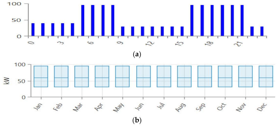
Using BRT station data, HOMER Pro estimates an average daily energy demand of 2130 kWh, a peak load of 142.5 kW, and a load factor of 62%. Figure 2 depicts the daily and seasonal load changes.

2.4. HRES Modeling

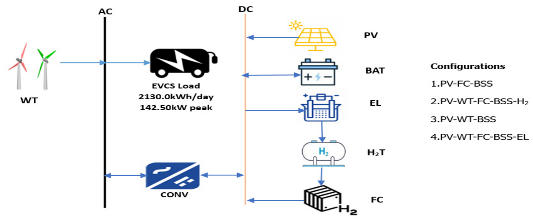
The hybrid energy system consists of solar photovoltaic (PV), wind turbines (WT), battery energy storage systems (BESS), and fuel cell (FC) units. It also has a hydrogen storage tank (H2T) for hydrogen production. BRT terminals serve as load centers, with total energy demand matching the scheduled charging needs of electric buses. Figure 3 shows the proposed HRES-powered electric vehicle charging system (EVCS).

2.4.1. Solar PV Model

The PV output power is computed using the module efficiency, total panel area, solar irradiance, and derating factor, as expressed in [22].
P P V ( t ) = η P V A P V G P V σ P V
where P P V ( t ) denotes PV power output at hour t (kW), η P V represents module efficiency (%), A P V is the total effective area of the PV modules (m2), G P V corresponds to the solar irradiance at hour t (kW/m2), while σ P V is the derating factor for system losses.

2.4.2. WT Model

The wind turbine (WT) power output is determined by the wind speed and the turbine’s power curve, as expressed in [23].
P W T ( t ) = 0   V t < V c i n P r α V t 3 β   V c i n V t P r   V r V t V c o V c o  
where coefficients α and β are determined as:
α = 1 V r 3     V c i n 3 ,   β = V c i n 3 V r 3     V c i n 3

2.4.3. FC Model

The electrical output of the fuel cell (FC) is determined by the hydrogen input and system efficiency, as described in [24].
P f c = η f c m f c ˙ L H V H 2
where m f c signifies hydrogen mass flow rate (kg/h), η f c denotes fuel efficiency and L H V H 2 represents the lower heating value of hydrogen (kWh/kg).

2.4.4. Electrolyzer Model

The amount of hydrogen produced from excess electrical energy is determined by the electrolyzer’s efficiency and hydrogen’s energy content [24]:
m H 2 ˙ =   η e l P e l L H V H 2
where η e l is the electrolyzer efficiency, P e l is the input electrical power (kW), and L H V H 2 denotes the lower heating value of hydrogen (kWh/kg).

2.4.5. H2T Storage Model

The hydrogen mass in storage is tracked over time and modeled as described in [10].
S H 2 ( t ) = S H 2 ( t 1 ) + P H 2   ( t ) C H 2 ( t )
where S H 2 ( t ) represents the hydrogen stored at time t (kg), P H 2 t   is the hydrogen produced by the electrolyzer at time t (kg), and C H 2 t   denotes the hydrogen consumed by the fuel cell at time t (kg).

2.4.6. BESS Model

The battery energy storage dynamics are dependent on the charging and discharging power and their corresponding efficiency [22].
S B E S S ( t ) = S B E S S ( t 1 ) + η c h P i n ( t ) · t P o u t ( t ) · t η d i s
The total charging and discharging powers are expressed as:
P i n t = P P V t + P W T t + P f c t   + P B E S S , d i s ( t ) P e l   P B E S S . c h ( t )
P o u t ( t ) = P E V C S
where S B E S S t   is the state of charge of the battery at time t (kWh), η c h and η d i s are the charging and discharging efficiencies, P i n ( t ) and P o u t ( t ) are the charging and discharging powers (kW), and Δ t is the time step (h).

2.4.7. Power Converter Model

The power output of a DC/AC or AC/DC converter depends on the input power and the conversion efficiency, η c o n v , which accounts for losses throughout the conversion process. The model can be represented as follows:
P c o n v ( t ) = η c o n v     P i n ( t )
where P c o n v ( t ) denotes converter output power at time t   (kW), while η c o n v   represents converter efficiency.

2.5. Objective Function

The objective function seeks to minimize the hybrid system’s total life cycle cost, which includes capital, replacement, fuel, operation and maintenance (O&M), and salvage costs. The formula for a 24 h horizon is given as:
m i n   J = i = 1 n C a p + C r e p + C f u e l + C O M C s v
where J denotes the system’s total life-cycle cost, expressed as the net present cost (NPC), i represents each component of the hybrid system, and each cost term corresponds to the respective system element.

2.5.1. Capital Cost (CAPEX)

Each component’s capital cost (CAPEX) is expressed as follows [22]:
C a p = U P V E P v β P V + U W T E W T β W T   + U f c E f c β f c + U e l E e l β e l   +   U B E B β B   +   U H 2 E H 2 β H 2
where U i represents number of units of component i, E i the rated power or energy of component i, and β i the cost per unit of the component.

2.5.2. Operating and Maintenance Cost

The operation and maintenance cost ( C O M ) of the HRES components is expressed as in [25].
C O M = i = 1 N θ i U i 1 + γ T p
where θ i denotes annual O&M cost per unit of component i ($/unit-year), U i is the no. of unit of component, γ represents annual discount, while T p is the project year (year).

2.5.3. Fuel Cost (Hydrogen/Fuel Cell)

The fuel cost of the hydrogen and fuel cell subsystems is expressed according the formulation [26].
C f u e l = u = 1 U f C H 2 P f c 1 + γ T P
Here C f u e l denotes the total fuel cost ($), while C H 2 is the fuel price per unit energy (USD/kWh) for hydrogen or fuel cell subsystems.

2.5.4. Replacement Cost

The replacement cost ( C r e p ) of the hybrid system components is determined using the approach provided in [27].
C r e p = i = 1 N r e p U i E i β 1 N r e p , i   1 + γ t r e p
where C r e p   denotes the total discounted replacement cost, N r e p , i represents replacement cost per unit, and t r e p is the year of the r -th replacement.

2.5.5. Salvage Cost

The cumulative salvage value (CSV) of the hybrid system components is determined as a percentage of the initial investment, which is set at 20%.
C S V = 0.2 C a p
where C s v   denotes the total salvage value and C a p is the initial capital cost of the system components.

2.6. Model Constraints

The proposed optimization methodology is based on system constraints to ensure operational feasibility and reliability.
P P V ( t ) + P W T ( t ) + P f c ( t ) + P B E S S , d i s ( t ) = P E V C S ( t ) + P e l   ( t ) + P B E S S , c h ( t )  
0 P P V ( t ) η P V A P V G P V ( t )
0 P f c ( t )     P f c m a x
S B E S S m i n     S B E S S ( t )     S B E E S S m a x
S H 2 m i n     S H 2 ( t )     S H 2 m a x
0   P c o n v ( t )     P c o n v m a x

2.7. Optimization Algorithm

The HRES-based EVCS for BRT infrastructure is optimized using HOMER Pro, considering system constraints like EV load demand, PV and WT generation profiles, battery and hydrogen storage capacity, fuel cell operation, and converter efficiency. The rated capacities of all components are employed as decision variables, and 24 h operational scenarios are investigated to provide a comprehensive techno-economic assessment of cost, dependability, and environmental impact. Four different hybrid energy configurations were studied for the case study using HOMER Pro’s hourly simulation data.
(1)
Config 1 (C1): PV + FC + BESS,
(2)
Config 2 (C2): PV + WT + FC + BESS + H2,
(3)
Config 3 (C3): PV + WT + BESS,
(4)
Config 4 (C4): PV + WT + FC + EL + BESS
The techno-economic specifications of all components are presented in Table 1, while the cost assumptions are given as follows:
Capital expenditure (CAPEX) consists of investment costs of all key components and is sought from related studies to provide a credible basis for cost estimation: PV [28], WT [29], EL [30], H2T [30], BESS-50% [31], FC [30], and CONV [32].
Operating and maintenance ( C O M ) costs are based on fixed percentages of each component’s CAPEX: PV-1% [28], WT-7% [29], EL-1% [30], H2T-1% [30], BESS-2% [31], FC-0.150$/h [30], CONV-1% [32]. Replacement costs ( C r e p _) are taken as fractions of CAPEX, aligned with component life cycle and manufacturer data: PV-70% [28], WT-85% [29], EL-75% [30], H2T 100% [30], BESS 50% [31], FC 89% [30], CONV 100% [32], and a discount rate (i) of 5.4% [22] for future financial value depreciation, while an inflation rate (r) of 2.5% [32] allows for future cost increases.

3. Results and Discussion

This section assesses the performance of the optimal hybrid renewable energy system (HRES) design for the BRT electric vehicle charging system (EVCS). The results encompass energy generation and storage characteristics, sensitivity analysis, cost assessment, and ecological impact. The optimal design is then compared to existing literature to emphasize its technological advantages and operational feasibility.

3.1. Optimal Hybrid System

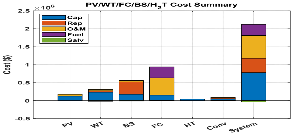
The PV-WT-FC-BESS-H2 hybrid system was the most efficient design, generating 1.88 GWh per year with a levelized cost of energy (COE) of $0.202/kWh and a net present cost (NPC) of $2.08 million. The system has 629 kW PV, 250 kW WT, 250 kW FC, 100 kg H2 storage, 318 kWh battery, and a 157 kW converter. Figure 4 depicts the cost breakdown, with capital and O&M costs accounting for the most significant portion, followed by fuel use, battery replacement, and the PV, WT, and hydrogen subsystems.

3.2. Optimal System Energy Dispatch

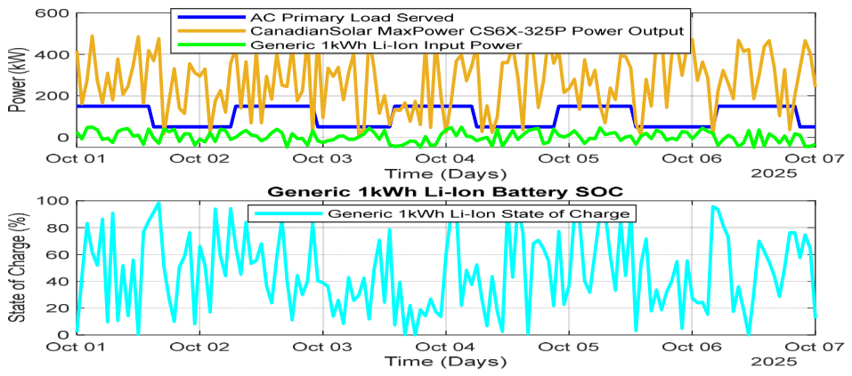
Figure 5 shows the weekly energy dispatch of the PV-WT-FC-BESS-H2 hybrid system during a 168 h period. Solar PV accounts for the majority of generating during the day, while battery and hydrogen storage systems provide energy during low sun and wind periods. The coordinated operation of these components results in a consistent and balanced energy flow that meets the EV charging demand successfully. To provide a consistent load supply, the Li-ion battery charges and discharges alternately. The state-of-charge (SOC) profile shows dynamic utilization, which results in excellent energy management and system dependability throughout the simulation period.

3.3. Optimal Hybrid System Emission Impact Asssessment

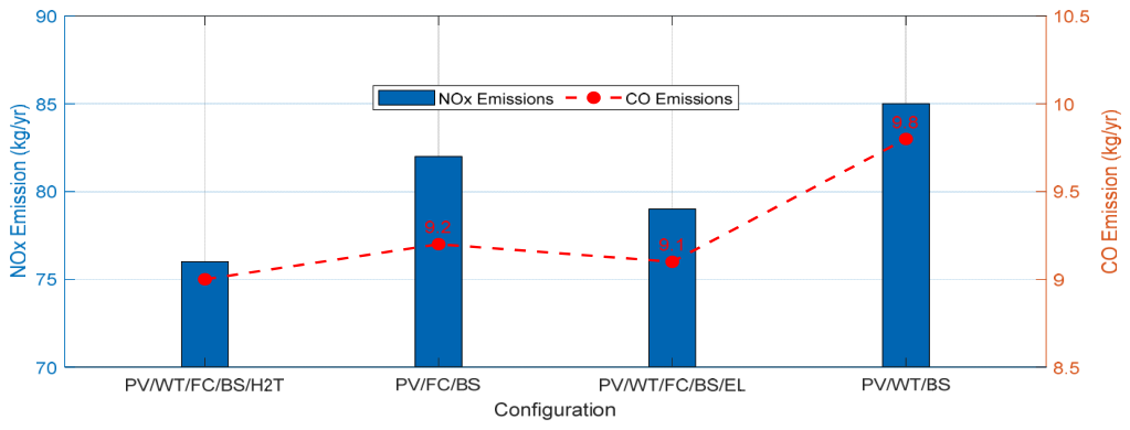
Emission and renewable energy fractions serve as crucial indicators of environmental performance in HRES assessments. Figure 6 shows that the hybrid PV-WT-FC-BESS-H2 system has moderate emissions due to the fuel cell’s reliance on stored hydrogen, yet renewable sources contribute approximately 78.0% of total energy supply. Figure 6 illustrates a comparison of emissions across all system configurations.

3.4. Sensitivity Analysis on Component Cost of Optimal System

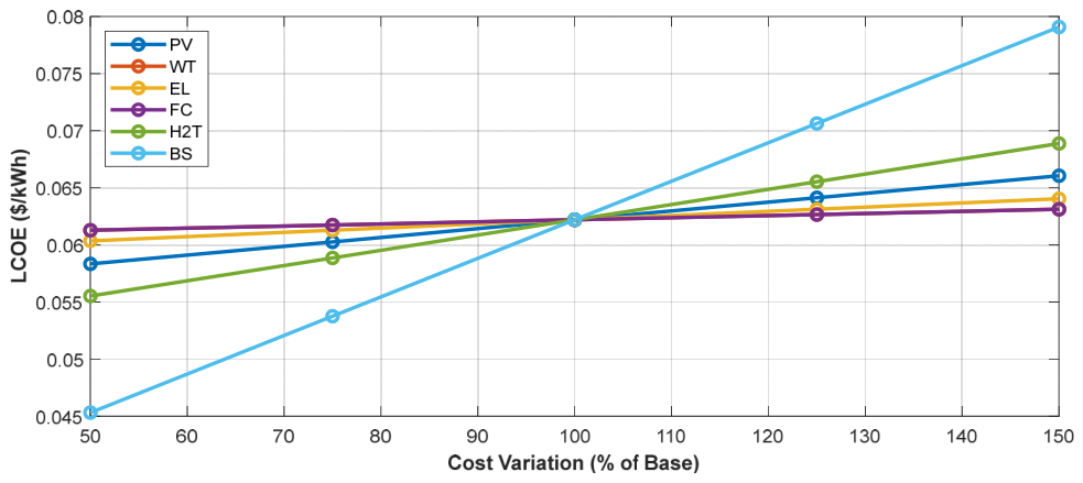
The sensitivity analysis in Figure 7 shows that battery storage and PV pricing are the system’s key economic drivers, having a significant impact on the LCOE. Hydrogen and fuel costs are moderately sensitive, whereas wind and electrolyzer costs have minor impact, indicating a lower economic significance.

3.5. Comparative Analysis of the Proposed Model with Recent Studies

Table 2 compares the proposed PV-WT-FC-BESS-H2 system with prior study results. The system’s LCOE of $0.202/kWh is consistent with the reported values. The slight price rise is primarily due to the addition of hydrogen storage and fuel cell units, demonstrating how increased system complexity can raise total costs.

4. Conclusions

The present study develops a PV-WT-FC-BESS-H2 hybrid system as a clean energy solution for the electrification of Lagos’s BRT network in Nigeria. The system generates 1.66 GWh of power per year with an LCOE of $0.202/kWh and an NPC of $2.08 million, demonstrating both technological viability and economic competitiveness. The use of hydrogen and battery storage improves reliability and ensures continuous power supply during low-renewable periods. Furthermore, the hybrid system significantly reduces carbon emissions when compared to grid-only charging alternatives, contributing to Nigeria’s transition to sustainable urban mobility. Consequently, the findings show the system’s potential as a scalable model for low-carbon transit in other developing cities.

Author Contributions

Conceptualization, A.A.O. and I.K.O.; methodology, A.A.O.; software, A.O.D.; validation, A.A.O., J.M.N. and W.K.K.; formal analysis, A.A.O.; investigation, A.O.D.; resources, I.K.O.; data curation, J.S. and A.A.O.; writing—original draft preparation, A.O.D.; writing—review and editing, A.A.O.; visualization, A.A.O.; supervision, M.M.; project administration, A.O.D.; funding acquisition, W.K.K. All authors have read and agreed to the published version of the manuscript.

Funding

This research received no external funding.

Institutional Review Board Statement

Not applicable.

Informed Consent Statement

Not applicable.

Data Availability Statement

Data is available on request.

Conflicts of Interest

The authors affirm that there is no conflict of interest regarding this work.

References

  1. Malik, M.A.I.; Kalam, A.; Ikram, A.; Zeeshan, S.; Zahidi, S.Q.R. Energy transition towards electric vehicle technology: Recent advancements. Energy Rep. 2025, 13, 2958–2996. [Google Scholar] [CrossRef] [Scilit]
  2. Ramkumar, G.; Kannan, S.; Mohanavel, V.; Karthikeyan, S.; Titus, A. The future of green mobility: A review exploring renewable energy systems integration in electric vehicles. Results Eng. 2025, 27, 105647. [Google Scholar] [CrossRef] [Scilit]
  3. Morales, R.R.; Manalastas, A.S. Exploring Instructional Leadership of School-Based Management Level III Schools. Int. J. Res. Publ. Rev. 2023, 4, 2798–2814. [Google Scholar] [CrossRef] [Scilit]
  4. Rahman, H.; Afsana, A.; Mim, U.A.; Jahan, E. Hybrid Energy-Based Battery Storage Swapping Station for Electrical Vehicles and Net Metering. In 2025 4th International Conference on Robotics, Electrical and Signal Processing Techniques (ICREST); IEEE: Piscataway, NJ, USA, 2025; pp. 317–321. [Google Scholar] [CrossRef] [Scilit]
  5. Alhayali, O.J.; Ataalla, A.F.; Alsultan, Q.H.; Shafeeq, A.F.; Aljanabi, S.; Jalil, M.A. Optimizing Hybrid Renewable Energy Systems for Electric Vehicle Charging Stations: A Feasibility Study in Iraqi Cities. J. Intell. Syst. Internet Things 2025, 17, 291–303. [Google Scholar] [CrossRef] [Scilit]
  6. Rehman, A.U.; Khalid, H.M.; Muyeen, S.M. Grid-integrated solutions for sustainable EV charging: A comparative study of renewable energy and battery storage systems. Front. Energy Res. 2024, 12, 1403883. [Google Scholar] [CrossRef] [Scilit]
  7. Ahmed, K.; Sakravdia, D.; Sharma, C. A Novel Integration Approach for Photovoltaic/Wind/Fuel Cell—Based Hybrid Renewable Energy Systems With Reliability Indices for Sustainable Electric Vehicle Charging. Fuel Cells 2025, 25, e70012. [Google Scholar] [CrossRef] [Scilit]
  8. Almutairi, A.; Albagami, N.; Almesned, S.; Alrumayh, O.; Malik, H. Optimal management of electric vehicle charging loads for enhanced sustainability in shared residential buildings. Front. Energy Res. 2024, 12, 1396899. [Google Scholar] [CrossRef] [Scilit]
  9. Dhawale, P.G.; Kamboj, V.K.; Bath, S.; Raboaca, M.S.; Filote, C. Integrating renewable energy and plug-in electric vehicles into security constrained unit commitment for hybrid power systems. Energy Rep. 2024, 11, 2035–2048. [Google Scholar] [CrossRef] [Scilit]
  10. Roslan, M.; Ramachandaramurthy, V.K.; Mansor, M.; Mokhzani, A.; Jern, K.P.; Begum, R.; Hannan, M. Techno-economic impact analysis for renewable energy-based hydrogen storage integrated grid electric vehicle charging stations in different potential locations of Malaysia. Energy Strat. Rev. 2024, 54, 101478. [Google Scholar] [CrossRef] [Scilit]
  11. Turkdogan, S. Design and optimization of a solely renewable based hybrid energy system for residential electrical load and fuel cell electric vehicle. Eng. Sci. Technol. Int. J. 2021, 24, 397–404. [Google Scholar] [CrossRef] [Scilit]
  12. Ayodele, T.; Yusuff, A.; Mosetlhe, T.; Ntombela, M. Hydrogen production using solar energy resources for the South African transport sector. Int. J. Sustain. Eng. 2021, 14, 1843–1857. [Google Scholar] [CrossRef] [Scilit]
  13. Mousa, M.M.; Saleh, S.M.; Samy, M.M.; Barakat, S. Optimizing grid-tied hybrid renewable systems for EV charging in Egypt: A techno-economic analysis. Results Eng. 2025, 27, 106103. [Google Scholar] [CrossRef] [Scilit]
  14. Mohammed, B.; Amine, E.F.; Nabil, E.A. Investigation of technoeconomic optimization for sizing renewable energy systems using metaheuristic and hybrid algorithms. Sci. Afr. 2025, 28, e02712. [Google Scholar] [CrossRef] [Scilit]
  15. Mohammed, A.; Saif, O.; Abo-Adma, M.A.; Elazab, R. Multiobjective optimization for sizing and placing electric vehicle charging stations considering comprehensive uncertainties. Energy Inform. 2024, 7, 131. [Google Scholar] [CrossRef] [Scilit]
  16. Güven; Fatih, A.; Yörükeren, N. A comparative study on hybrid GA-PSO performance for stand-alone hybrid energy systems optimization. Sigma J. Eng. Nat. Sci. 2024, 42, 1410–1438. [Google Scholar] [CrossRef] [Scilit]
  17. Bade, S.O.; Tomomewo, O.S.; Meenakshisundaram, A.; Dey, M.; Alamooti, M.; Halwany, N. Multi-Criteria Optimization of a Hybrid Renewable Energy System Using Particle Swarm Optimization for Optimal Sizing and Performance Evaluation. Clean Technol. 2025, 7, 23. [Google Scholar] [CrossRef] [Scilit]
  18. Al-Shammari, Z.W.J.; Azizan, M.M.; Rahman, A.S.F.; Hasikin, K. Optimal sizing of standalone for hybrid renewable energy system by using PSO optimization technique. Int. J. Power Electron. Drive Syst. (IJPEDS) 2023, 14, 426–432. [Google Scholar] [CrossRef] [Scilit]
  19. Jaman, S.; Verbrugge, B.; Zhaksylyk, A.; Geury, T.; El Baghdadi, M.; Hegazy, O. Development of Smart Charging Scheduling and Power Management Strategy of a PV-ESS based Scalable EV Charging Station. Transp. Res. Procedia 2023, 72, 1240–1247. [Google Scholar] [CrossRef] [Scilit]
  20. El-Fedany, I.; Kiouach, D.; Alaoui, R. A smart management system of electric vehicles charging plans on the highway charging stations. Indones. J. Electr. Eng. Comput. Sci. 2021, 23, 752–759. [Google Scholar] [CrossRef] [Scilit]
  21. Franco, F.L.; Mandrioli, R.; Ricco, M.; Monteiro, V.; Monteiro, L.F.C.; Afonso, J.L.; Grandi, G. Electric Vehicles Charging Management System for Optimal Exploitation of Photovoltaic Energy Sources Considering Vehicle-to-Vehicle Mode. Front. Energy Res. 2021, 9, 716389. [Google Scholar] [CrossRef] [Scilit]
  22. Okubanjo, A.A.; Okandeji, A.; Okakwu, I.K.; Akinloye, B.; Olayiwola, A. Optimal Design of an Off-grid Hybrid Renewable Systems with Battery Storage for Rural Electrification of Academic Community in Ibogun Campus, Nigeria. MEJ Mansoura Eng. J. 2025, 50, 4. [Google Scholar] [CrossRef] [Scilit]
  23. Suresh, V.; Muralidhar, M.; Kiranmayi, R. Modelling and optimization of an off-grid hybrid renewable energy system for electrification in a rural areas. Energy Rep. 2020, 6, 594–604. [Google Scholar] [CrossRef] [Scilit]
  24. Ahmed, M.M.; Das, B.K.; Das, P.; Hossain, S.; Kibria, G. Energy management and sizing of a stand-alone hybrid renewable energy system for community electricity, fresh water, and cooking gas demands of a remote island. Energy Convers. Manag. 2024, 299, 117865. [Google Scholar] [CrossRef] [Scilit]
  25. Cardenas, G.A.R.; Khezri, R.; Mahmoudi, A.; Kahourzadeh, S. Optimal Planning of Remote Microgrids with Multi-Size Split-Diesel Generators. Sustainability 2022, 14, 2892. [Google Scholar] [CrossRef] [Scilit]
  26. Fontalvo, V.M.; Nelson, G.J.; Pupo-Roncallo, O.; Sanjuan, M.E.; Gómez, H.A. A techno-economic assessment for fuel cells hybrid systems in stationary applications. Int. J. Sustain. Energy 2023, 42, 889–912. [Google Scholar] [CrossRef] [Scilit]
  27. Wali, S.; Hannan, M.; Ker, P.J.; Rahman, M.A.; Tiong, S.; Begum, R.; Mahlia, T.I. Techno-economic assessment of a hybrid renewable energy storage system for rural community towards achieving sustainable development goals. Energy Strat. Rev. 2023, 50, 101217. [Google Scholar] [CrossRef] [Scilit]
  28. Farhadi, A.; Iqbal, M.T. Optimal Sizing and Techno-Economic Analysis of a Hybrid Power System for Postville. Eur. J. Eng. Technol. Res. 2024, 9, 5–12. [Google Scholar] [CrossRef] [Scilit]
  29. Ali, M.B.; Altamimi, A.; Kazmi, S.A.A.; Khan, Z.A.; Alyami, S. Techno-economic-environmental optimization of on-grid hybrid renewable energy-electric vehicle charging stations in BTS infrastructure. Energy Convers. Manag. X 2024, 23, 100644. [Google Scholar] [CrossRef] [Scilit]
  30. Soomro, A.M.; Rathi, M.K.; Shaikh, A.; Kumar, L.; Assad, M.E.H.; Ehyaei, M. Techno-economic analysis of stand-alone hybrid PV-hydrogen-based plug-in electric vehicle charging station. Energy Rep. 2024, 12, 3279–3290. [Google Scholar] [CrossRef] [Scilit]
  31. Mayyas, A.; Chadly, A.; Amer, S.T.; Azar, E. Economics of the Li-ion batteries and reversible fuel cells as energy storage systems when coupled with dynamic electricity pricing schemes. Energy 2022, 239, 121941. [Google Scholar] [CrossRef] [Scilit]
  32. Ennemiri, N.; Berrada, A.; Emrani, A.; Abdelmajid, J.; El Mrabet, R. Optimization of an off-grid PV/biogas/battery hybrid energy system for electrification: A case study in a commercial platform in Morocco. Energy Convers. Manag. X 2023, 21, 100508. [Google Scholar] [CrossRef] [Scilit]
  33. Mohamud, F.A.; Çetinbaş, I.; Demirtaş, M.; Erkaya, H.H. Designing and optimizing a hybrid microgrid supplying various electric vehicle charging modes. Pamukkale Univ. J. Eng. Sci. 2023, 29, 701–710. [Google Scholar] [CrossRef] [Scilit]
  34. Jailani, N.L.M.; Chen, C.P.; Tan, C.H.; Milano, J.; Alkawsi, G.; Lim, C.W.; Tiong, S.K. Sustainable integration of wind and grid resources for electric vehicles charging in low wind speed region: A techno-economic assessment. Energy Convers. Manag. X 2025, 27, 101118. [Google Scholar] [CrossRef] [Scilit]
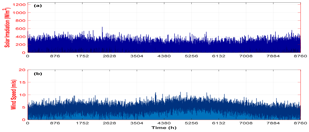
Figure 1. Hourly (a) solar irradiation and (b) wind speed.
Engproc 140 00032 g001
Figure 2. (a) Daily EVCS demand profile at CMS, (b) seasonal EV load profile.
Engproc 140 00032 g002
Figure 3. Proposed hybrid renewable energy-driven EV charging system for BRT networks.
Engproc 140 00032 g003
Figure 4. Cost distribution in optimal HRES.
Engproc 140 00032 g004
Figure 5. Energy dispatch and SOC of the optimal hybrid system.
Engproc 140 00032 g005
Figure 6. Emissions comparisons of all system configuration.
Engproc 140 00032 g006
Figure 7. Impact of component cost variations on system LCOE.
Engproc 140 00032 g007
Table 1. Technical specifications of HRES components for BRT EVCS.
SubsystemModelKey ParametersValuesUnits
Solar PVCS6X325PPmax, Imp, Vmp, VOC, ISC, ηPV, Gref, τPV, γ, Tref, TNOCT0.325, 8.78, 37.0, 45.5, 9.34, 16.94, 1000, 88, −0.41, 25, 45 ± 2kW, A, V, V, A, %, W/m2, %, %/°C, °C, °C
Wind TurbineEnneraSPr, Vci, Vco, Vr, Hhub, A, Cp, ρr, RD, Nmax, Tts, NB3.2,3.0, 25.0, 11.0, 12.0, 14.9, 42, 1.08, 16.94, 1000, 88, 3kW, m/s, m/s, m/s, m, m2, %, kg/m3, —, rev/m, m/s, —
Fuel Cell/Electrolyzer/H2 TankGenericPel, Vcells, ηel, ṅH2, ηfc, HHV H250, 0.75, 85, 3.0, 75, 14.9kW, V, %, kg/h, %, kWh/
Battery Storage (BESS)GenericCah, Vb, Idis, max, Ich, max, ηconv, ηch, ηdis, ηPV, DOD, Enom, ηrt, SOCmax, SOCmin167, 6, 500, 167, 95, 90, 80, 16.94, 90, 1, 95, 100, 20Ah, V, A, A, %, %, %, %, %, kWh, %, %, %
Table 2. Comparison of HRES for EV and hydrogen applications.
ConfigurationRegionLCOE ($/kWh)ApplicationRef
PV-WT-BS-DGTurkey0.075Campus EVCS[33]
PV-WT-GRMalaysia0.026Airport EVCS[34]
PV-H2South Africa0.245Hydrogen fueling[12]
PV-WT-FC-BESS-H2Nigeria0.202BRT EVCSNovel study
DG-Diesel Generator, GR-Grid Network.
Disclaimer/Publisher’s Note: The statements, opinions and data contained in all publications are solely those of the individual author(s) and contributor(s) and not of MDPI and/or the editor(s). MDPI and/or the editor(s) disclaim responsibility for any injury to people or property resulting from any ideas, methods, instructions or products referred to in the content.