Proceeding Paper

Experimental Comparison of PI and PID for Field Excitation in a Synchronous Condenser †
Department of Electrical Engineering, Nelson Mandela University, Gqeberha 6031, South Africa
*
Author to whom correspondence should be addressed.
Presented at the 34th Southern African Universities Power Engineering Conference (SAUPEC 2026), Durban, South Africa, 30 June–1 July 2026.
Eng. Proc. 2026, 140(1), 35; https://doi.org/10.3390/engproc2026140035
Published: 27 May 2026

Abstract

This paper presents an experimental comparison of proportional–integral (PI) and proportional–integral–derivative (PID) controllers for excitation regulation in a 1.5 kW synchronous condenser. The excitation current was controlled using a PWM-based converter driven by an ESP32 microcontroller, with reactive power feedback. Both controllers were tested across multiple reactive power setpoints to evaluate settling time and steady-state accuracy performance. The results show that both achieved steady-state errors within ±5% of the reference. The PI controller provided faster settling, while the PID controller offered smoother but slower responses due to feedback bandwidth limitations. The findings confirm that PI control is an effective and low-computational-cost solution for embedded excitation systems.

1. Introduction

Maintaining voltage stability and reactive power balance remains a key challenge in modern renewable-based power systems. The increasing penetration of inverter-fed sources has displaced traditional synchronous machines that once formed the backbone of system stability, resulting in reduced inertia, lower fault levels, and weakened voltage regulation capability [1,2].
To mitigate these effects, synchronous condensers (SCs) have re-emerged as effective dynamic compensators, capable of providing both reactive power and rotational inertia to the grid [3,4]. Their ability to absorb or supply reactive power by varying the excitation current enables dynamic voltage support without mechanical coupling [1]. The relationship between field current and reactive power is well established through the classical V-curve, which forms the foundation for excitation control [1,5].
Classical excitation regulation of synchronous machines has traditionally relied on proportional–integral (PI) and proportional–integral–derivative (PID) control due to their simplicity and robustness. Reference [2] implemented a PI controller to enhance the power factor of a synchronous motor, achieving improved steady-state performance under fixed-speed operation. Similarly, ref. [6] explored a PSO-based PID approach, demonstrating faster settling with reduced overshoot compared to conventional tuning.
To overcome the limitations of conventional PI/PID control, advanced excitation strategies including PIDA, and robust H-infinity-based schemes have been introduced in the recent literature. Reference [4] introduced a PIDA excitation controller that improved voltage stability and transient damping, while recent works have extended this approach through optimization and adaptive mechanisms.
At the power-system scale, ref. [7] demonstrated that a synchronous condenser equipped with fast excitation control can significantly improve transient and dynamic stability in long-distance transmission systems by enhancing damping and synchronizing torque. Their application of an H−∞ controller further emphasized the potential of excitation control as an effective stabilizing mechanism.
Despite the extensive literature on simulated and dynamic studies, few studies experimentally compare these controllers in an unloaded synchronous condenser where electrical dynamics dominate, and derivative action contributes little improvement under low-bandwidth feedback [4,6]. This study addresses that gap by experimentally comparing PI and PID controllers implemented on an ESP32-based hardware platform for regulating the excitation current of a 1.5 kW synchronous condenser. The focus is on evaluating steady-state accuracy, settling time, and response smoothness across multiple excitation levels.

2. Theory of Operation

A synchronous condenser is fundamentally a synchronous motor operating without a mechanical load and with adjustable DC excitation applied to its field winding. When connected to an AC network, the condenser can either absorb or supply reactive power depending on the level of excitation. This property allows it to regulate the system voltage and improve power factor stability in renewable-heavy grids [1,3].
Under normal operation, the internal generated emf E f in the machine is directly proportional to the field current I f and the number of turns on the rotor winding, as described by [1,5], and expressed as:
E f = k   · N f · I f
where k is a proportionality constant determined by the machine’s design.
The reactive power Q , derived from classical power–angle relationships in [1,5], is given as:
Q   =   3   V t X s   V t   E f cos δ
where V t is the terminal voltage, X s is the synchronous reactance, and δ is the torque angle. For an unloaded condenser, δ is small, and variations in I f cause Q to shift from lagging to leading regions. This relationship forms the basis of the V–curve, where the stator current I s varies nonlinearly with I f .
For voltage control, the excitation voltage V f applied to the rotor winding determines I f according to the DC excitation circuit model described in [8,9]:
I f   =   V f R f
where R f is the rotor field resistance. Thus, by modulating V f via PWM, the system indirectly controls the reactive power flow.
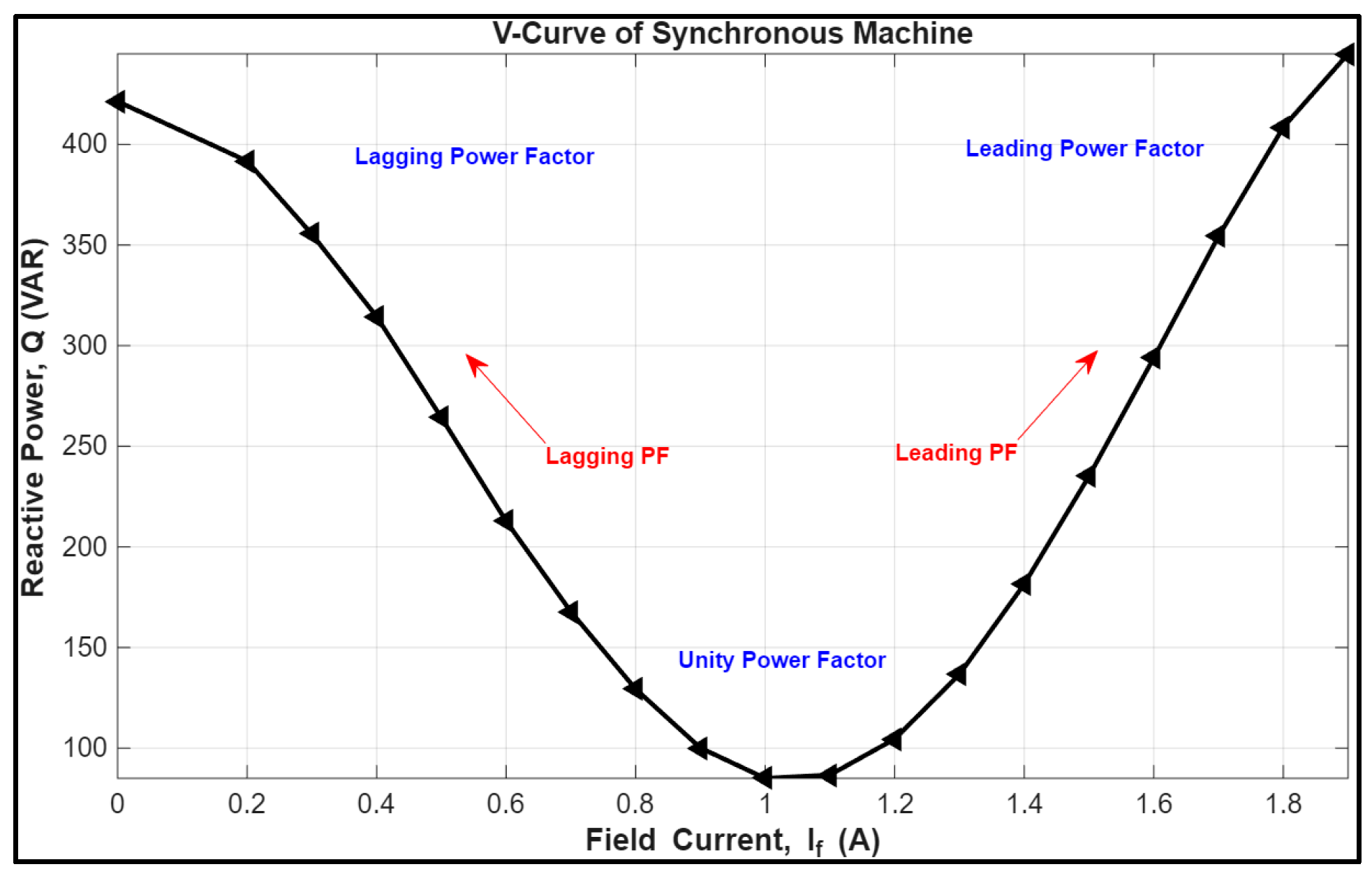
These relationships form the basis for feedback-based PI and PID excitation control. The controller compares the measured reactive power Q m with the desired setpoint Q r e f and adjusts V f accordingly, allowing the synchronous condenser to maintain voltage support dynamically without external mechanical input [2,10]. The experimentally obtained V-curve in Figure 1 confirms the expected relationship between field current and reactive power, demonstrating the transition from lagging to leading operation as excitation increases.

3. System Overview

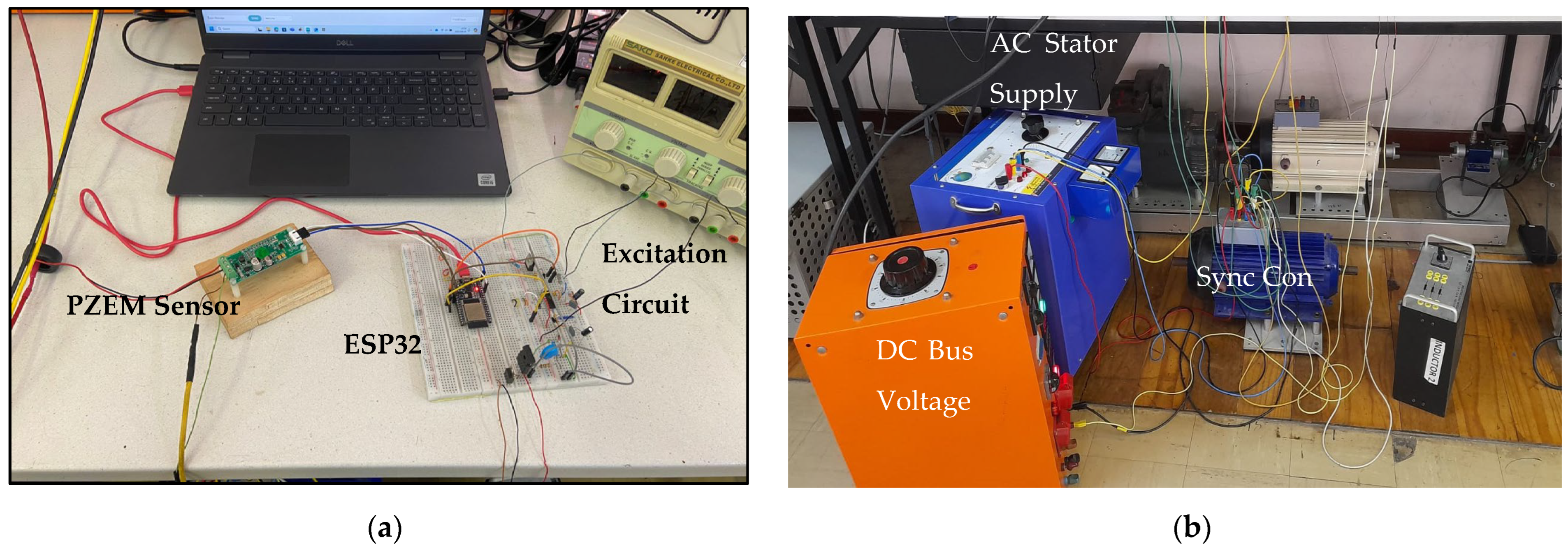
The experimental setup consisted of a laboratory-scale 1.5 kW, 380 V, 1500 rpm salient-pole synchronous motor configured as a condenser and supplied from a 380 V, 50 Hz three-phase source. The excitation current was regulated through a controllable DC circuit driven by a half-bridge converter, as shown schematically in Figure 2a. Figure 2b presents the corresponding power-stage layout, indicating the main supply connections and DC bus interface.

3.1. Power and Machine Subsystem

Operating the synchronous motor without mechanical load eliminated torque-related dynamics, allowing the investigation to focus purely on electrical excitation behaviour. The relationship between excitation voltage and reactive power followed the theoretical V-curve characteristic described by [1,5], where increases in field current raise the internal generated emf, shifting the power factor from lagging to leading.

3.2. Excitation Circuit and Driver Stage

The excitation driver employed a half-bridge configuration built around the IR2110 gate driver, a high-side IGBT (IKW15N120CS7), and a low-side MOSFET (IRF540). This configuration enabled bidirectional current modulation with galvanic isolation and sufficient voltage headroom. The IR2110 was chosen for its compatibility with 3.3 V logic and ±18 V gate-drive capability. Key passive components such as bootstrap capacitors, flyback diodes, and gate resistors were selected to minimize switching transients and maintain device safety.

3.3. Sensing and Measurement

System variables, including RMS voltage, RMS current, power factor, and active power, were monitored using a PZEM-004T sensor module [11].
According to the manufacturer, the module provides ±0.5% accuracy for voltage, current, and power measurements (±1% for power factor), with resolutions of 0.1 V, 0.001 A, and 0.1 W. Communication with the ESP32 was performed via Modbus RTU, yielding an effective measurement update rate of approximately 10 Hz.
The control loop is executed at a fixed interval of 20   m s (50 Hz). A moving average filter with a five-sample window was applied to the reactive power signal prior to control action, corresponding to a 100   m s smoothing window.
Due to the sensor internally computing active power and power factor, this enabled the estimation of reactive power as presented by [2]:
Q = sin ( p f ) S 2 P 2
This approach simplified implementation by avoiding the need for zero-crossing detection or explicit phase-angle computation, which are common in conventional laboratory setups.

3.4. Control Platform and Interface

Control was implemented on an ESP32 microcontroller using PWM generation at 1–2 kHz with embedded dead-time management. The ESP32 interfaced with a Node-RED dashboard to log and visualize system behaviour in real time. Sampling and update rates were adjusted to balance speed and stability of the measured quantities.

3.5. Safety Considerations

Electrical isolation between the logic and power domains was maintained using optocouplers and galvanic isolation stages. Standard laboratory safety measures were followed, including fuses and PPE, while the condenser’s unloaded configuration minimized mechanical risk.

4. Controller Design and Implementation

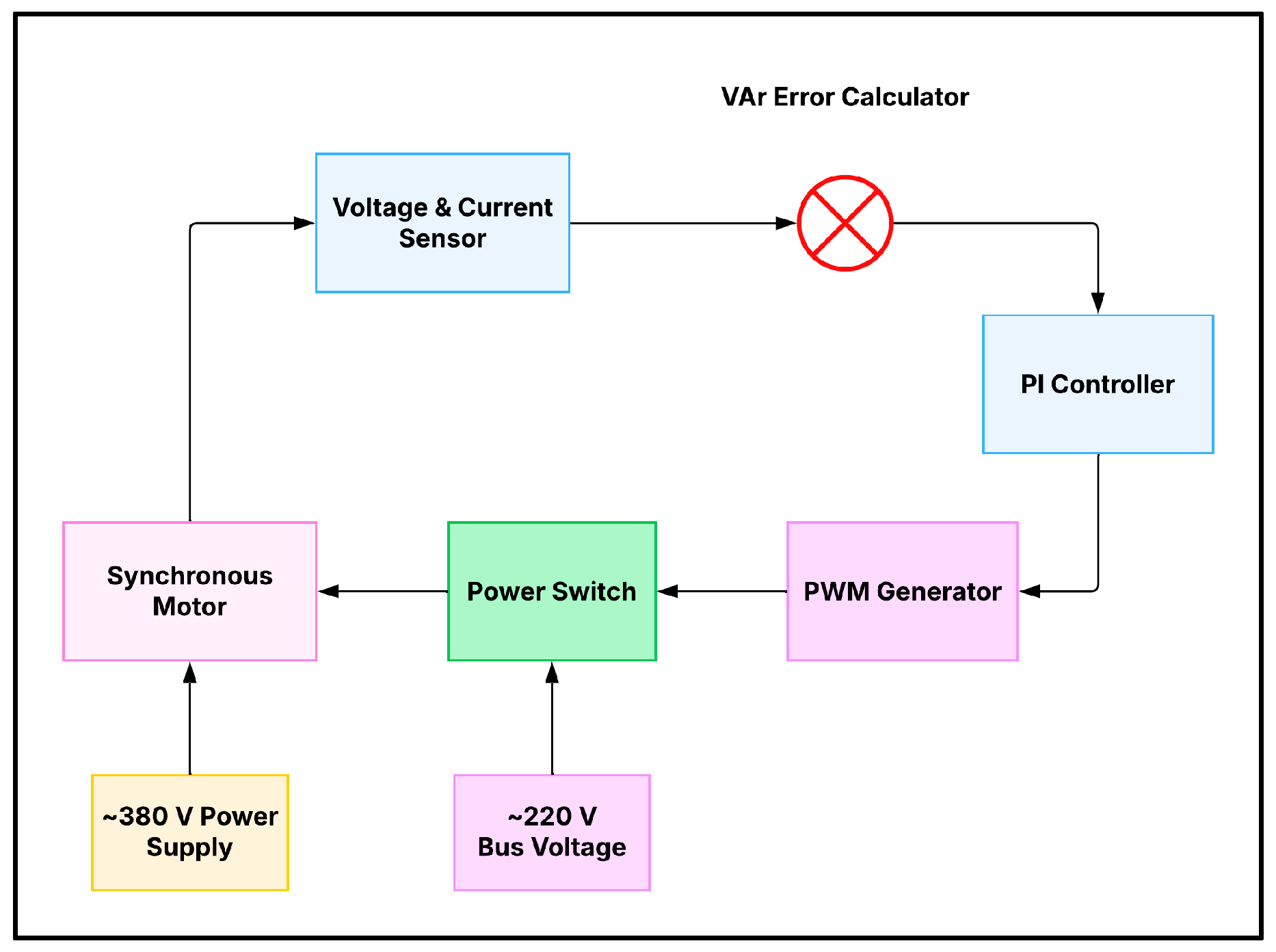
The control goal was to regulate the measured reactive power Q m to follow a predefined reference Q r e f by dynamically adjusting the excitation voltage applied to the rotor field circuit. Figure 3 illustrates the control topology.

4.1. Control Equations

The general PI control law, as defined by [12] is expressed as:
u t = K p e t + K i e t d t
and the PID law, also introduced by [12], is given by:
u t = K p e t + K i e t d t +   K d d e ( t ) d t
where e t = Q r e f Q m is the control error, and u t represents the PWM duty-cycle command that modulates the excitation current.
In a steady state, the integral term eliminates any residual error, while the proportional term ensures immediate correction. The derivative component provides predictive damping during transitions, although its benefit is reduced under noise-limited or slowly varying electrical systems [6].

4.2. Gain Tuning Strategy

Initial gain values were conceptually guided by Ziegler–Nichols rules, but final tuning was performed empirically on the hardware under real-time observation of overshoot, oscillation, and settling time. This approach ensured stable behaviour under sensor noise and converter nonlinearities. Gains were incrementally refined across multiple excitation levels until the desired steady-state accuracy was achieved.
At higher excitation voltages, proportional gains were slightly reduced to improve damping in the mid-range setpoints and to minimize steady-state bias. The final controller gain parameters used for all subsequent performance tests are listed in Table 1.
Controller gains were obtained iteratively. For the PID controller, while the PI variant omitted K d . Gains were reduced empirically at higher excitation levels to improve damping and minimize steady-state bias.

4.3. PWM–Excitation Mapping

The relationship between the PWM duty cycle D and the resulting excitation voltage V f follows the proportional mapping established experimentally in the present work:
V f = D · V b u s
Calibration revealed that the effective duty ratio decreased at low switching levels due to bootstrap capacitor charging and gate propagation delays. Empirical correction factors were implemented in the control firmware to linearize the response.

4.4. Implementation Architecture

Both controllers were executed on the ESP32 using the Arduino framework. The measured values of V , I , P and Q were filtered using a moving average routine before entering the control algorithm. The PWM outputs were synchronized to avoid overlap in complementary switching. All data were streamed to the Node-RED dashboard for monitoring and post-processing. This configuration allowed stable closed-loop control and real-time visualization of system response.

4.5. Performance Evaluation Criteria

Settling time was defined as the earliest time at which the reactive power response entered and subsequently remained within a ±5% tolerance band around the final setpoint value. For all reported cases, the response remained within this band for the remainder of the 60 s observation window, confirming steady-state convergence.
Steady-state ripple was quantified as the peak-to-peak variation across the final ten consecutive measurements recorded during the steady-state portion of the 60 s interval. This method isolates steady-state fluctuations from transient behaviour and ensures consistent comparison across all setpoints.
The steady-state value used for error computation was obtained as the arithmetic mean of these final ten readings.

5. Results and Discussion

Both PI and PID controllers were tested under identical laboratory conditions to regulate reactive power at six setpoints: 90, 120, 150, 180, 200, and 250 VAR, respectively. The primary evaluation metrics were steady-state error and settling time, evaluated according to the criteria in Section 4.5.

5.1. Quantitative Comparison

Table 2 summarizes the performance metrics for each controller across all excitation setpoints. The PI controller consistently achieved faster settling times, at lower ripple values, while the PID controller provided smoother responses with slightly slower dynamics.
During initial testing, a PI controller tuned using simulation-based gains produced oscillatory “on–off” behaviour in hardware. The issue was first suspected to arise from the controller structure, leading to the inclusion of a derivative term. Subsequent experiments demonstrated that the instability was primarily gain-related: after retuning, the PI controller achieved faster convergence and stable operation. This finding shows that proportional–integral control is adequate for the system and that derivative action was not strictly necessary under the hardware’s sensing constraints.

5.2. Performance Trends

The PID controller, by contrast, provided smoother damping but required more time to settle. Both controllers maintained acceptable steady accuracy. Steady-state ripple analysis further showed that the PI controller achieved consistently low variation, while the PID controller displayed slightly higher fluctuations at higher excitation levels, possibly due to its sensitivity to small measurement changes.
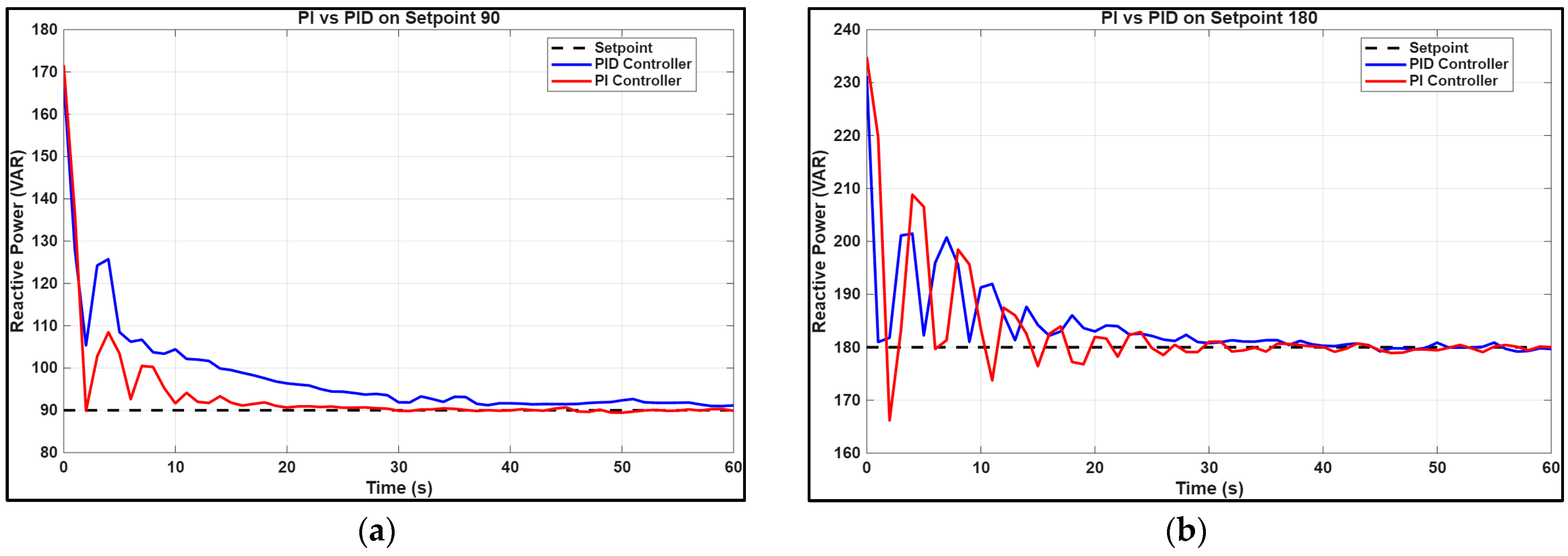
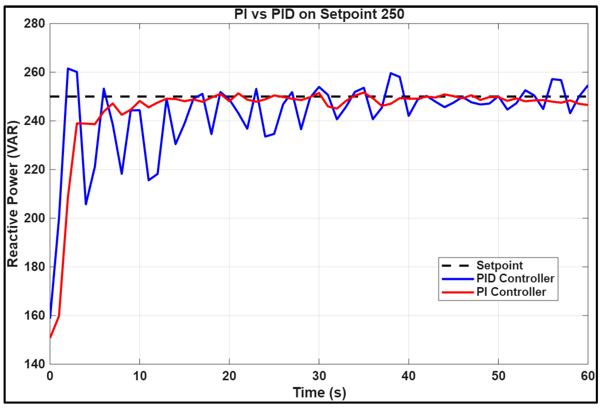
Representative time-domain responses are illustrated in Figure 4a,b and Figure 5 for low (90 VAR), medium (180 VAR), and high (250 VAR) excitation levels. The PI controller shows sharp convergence with minor oscillation, whereas the PID controller exhibits slower but more stable transitions.
To summarize overall controller performance, steady-state error and settling-time values were extracted from the final portions of each response after the system had reached steady state. The mean of the last ten recorded readings was used to represent the steady-state value for each case, from which the average performance metrics were computed. The resulting comparison between the PI and PID controllers is presented in Table 3.

5.3. Interpretation of Results

The experimental results confirm the expected trade-off between response speed and damping. PI control achieved faster regulation, while PID control provided smoother transitions at the expense of speed. The limited measurement bandwidth imposed by the PZEM-004T sensor limited the derivative term’s effectiveness, resulting in minimal performance improvement over PI control. These results align with prior studies that reported limited benefit of derivative action in low-bandwidth feedback conditions [2,6].

5.4. Practical Implications

For low-cost embedded excitation systems, such as those implemented on ESP32 platforms, the PI controller offers an optimal balance between simplicity, computational efficiency, and response speed. PID control may become advantageous only when higher-resolution sensors or faster data acquisition hardware are available.

6. Conclusions

This paper presented an experimental comparison of PI and PID control strategies for regulating the excitation current of a 1.5 kW synchronous condenser. Both controllers achieved satisfactory steady-state tracking performance. The PI controller demonstrated faster settling and satisfactory accuracy, while the PID controller produced smoother but slower transitions due to feedback bandwidth limits from the PZEM-004T sensor. Overall, the results confirm that PI control provides a practical and low-computational-cost solution for embedded excitation systems, offering effective performance without additional tuning complexity. PID control may become advantageous only when higher-bandwidth sensors or faster data-acquisition platforms are available. Future work will focus on improving measurement resolution and adaptive gain tuning to enhance controller scalability for grid-interactive applications.

Author Contributions

Conceptualization, K.R. and L.M.; methodology, K.R. and L.M.; software, L.M.; validation, L.M., K.R. and E.C.; formal analysis, L.M., K.R. and E.C.; investigation, L.M. and K.R.; resources, K.R.; data curation, L.M. and K.R.; writing—original draft preparation, L.M.; writing—review and editing, K.R. and E.C.; visualization, L.M.; supervision, K.R.; All authors have read and agreed to the published version of the manuscript.

Funding

This research received no external funding.

Institutional Review Board Statement

Not applicable.

Informed Consent Statement

Not applicable.

Data Availability Statement

The raw data supporting the conclusions of this article will be made available. Available from the authors on request.

Conflicts of Interest

The authors declare no conflict of interest.

References

  1. Kundur, P. Power System Stability and Control; McGraw-Hill: New York, NY, USA, 1994. [Google Scholar]
  2. Pengpraderm, S.; Atchariyawut, K.; Srisakulchai, A. Automatic control of synchronous motor using PI controller for improving power factor. J. Thai Interdiscip. Res. 2017, 12, 35–41. [Google Scholar]
  3. Tao, Z.; Wang, T.; Cai, D.; Chen, R. Reactive power optimization of synchronous condensers in HVDC transmission systems. Energies 2024, 17, 4294. [Google Scholar] [CrossRef]
  4. Yuan, X.; Ma, H.; Cui, C.; Liu, M.; Gao, Z. Research on impact of synchronous condenser excitation strategy based on PIDA controller and feedforward voltage control on transient voltage of grid. Int. J. Electr. Power Energy Syst. 2024, 162, 110262. [Google Scholar] [CrossRef]
  5. Chapman, S.J. Electric Machinery Fundamentals, 4th ed.; McGraw-Hill: New York, NY, USA, 2005. [Google Scholar]
  6. Gani, A.; Hasan, M.Y.; Rahman, M.A.R. A simulation study on controlling excitation current of synchronous motor and reactive power compensation via PSO-based PID and PID controllers. J. Intell. Syst. Appl. 2018, 1, 103–110. [Google Scholar] [CrossRef]
  7. Katsuya, Y.; Mitani, Y.; Tsuji, K. Power system stabilization by synchronous condenser with fast excitation control. In Proceedings of the PowerCon 2000—International Conference on Power System Technology, Perth, WA, Australia, 4–7 December 2000. [Google Scholar] [CrossRef]
  8. Sen, P.C. Principles of Electric Machines and Power Electronics, 3rd ed.; Wiley: Hoboken, NJ, USA, 2013. [Google Scholar]
  9. El-Hawary, M.E. Principles of Electric Machines with Power Electronic Applications; Prentice-Hall: Englewood Cliffs, NJ, USA, 1986. [Google Scholar]
  10. Bao, L.; Fan, L.; Miao, Z. Comparison of synchronous condenser and STATCOM for wind farms in weak grids. In Proceedings of the 52nd North American Power Symposium (NAPS), Tempe, AZ, USA, 11–13 April 2021. [Google Scholar] [CrossRef]
  11. Peacefair. PZEM-004T V3.0 AC Communication Module Datasheet. Available online: https://www.mantech.co.za/datasheets/products/pzem-004t-250109a.pdf (accessed on 12 September 2025).
  12. Ogata, K. Modern Control Engineering, 5th ed.; Prentice Hall: Upper Saddle River, NJ, USA, 2010. [Google Scholar]
Figure 1. Experimental V-curve showing variation in reactive power vs. field current.
Engproc 140 00035 g001
Figure 2. (a) Control and measurement setup (ESP32, PZEM-004T, and power switch). (b) Power stage setup (synchronous motor and supply units).
Engproc 140 00035 g002
Figure 3. Closed loop diagram.
Engproc 140 00035 g003
Figure 4. (a) Step Response at 90 VAR. (b) Step Response at 180 VAR.
Engproc 140 00035 g004
Figure 5. Step Response at 250 VAR.
Engproc 140 00035 g005
Table 1. Final Controller Gains.
Controller K p K i K d
PI0.90.22-
PID0.90.10 0.02
Table 2. Results Across Setpoints.
ControllerSetpointSteady State Error (%)Settling Time (s)Steady State Ripple (VAR)
PI900.018190.78
1200.12572.47
1500.142203.1
1800.022232.19
2000.166191.29
2500.83123.64
PID901.823372.05
1200.136291.59
1500.473285.92
1800.102232.37
2000.627333.19
2500.8684519.76
Table 3. Average Performance.
ControllerSteady State Error (%)Settling Time (s)
PI0.21716.667
PID0.52932.5
Aggregate metrics of controllers.
Disclaimer/Publisher’s Note: The statements, opinions and data contained in all publications are solely those of the individual author(s) and contributor(s) and not of MDPI and/or the editor(s). MDPI and/or the editor(s) disclaim responsibility for any injury to people or property resulting from any ideas, methods, instructions or products referred to in the content.