


Abstract
The automotive sector is a major contributor to CO2 emissions, and hydrogen-fueled internal combustion engines offer a promising zero-carbon alternative. However, lean hydrogen combustion requires high air throughput and presents unique engineering challenges. This study investigated the dynamic balancing of a six-cylinder opposed-piston two-stroke hydrogen engine, analyzing different crankshaft configurations (60° and 120° crank throws), rotation directions (co-rotating versus counter-rotating), and phase angles. Results showed trade-offs between natural balancing, torque regularity, and gas scavenging efficiency. The optimal configuration depends on offset presence and crank phasing angle. The study provides a methodology and design guidelines for hydrogen and other alternative-fueled engines.
1. Introduction
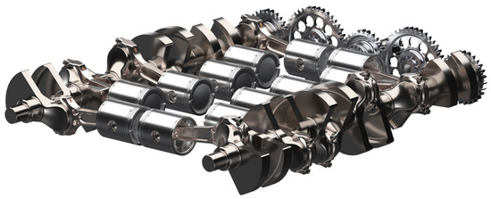
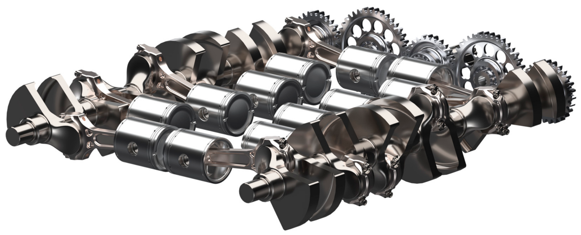
Reducing carbon emissions is a critical priority in the fight against climate change [1]. While electric vehicles represent a promising solution, their widespread adoption faces major limitations, including infrastructure demands and reliance on critical raw materials like lithium and cobalt, concentrated in a few countries [2]. In this context, internal combustion engines powered by carbon-neutral fuels, especially hydrogen, might play a vital transitional role. Hydrogen might offer clean combustion thanks to its carbon-free nature, but it presents non-trivial challenges [3]. Its low density reduces volumetric efficiency, especially with port injection, making direct injection necessary to maintain performance. However, direct injection brings risks such as backfire due to the wide flammability range of hydrogen [4,5,6]. Moreover, even though hydrogen contains no carbon, it can still produce NOx emissions because these depend on combustion temperature and oxidizer, not fuel type. Controlling combustion temperature is thus crucial [7,8]. The wide flammability range of hydrogen allows the use of ultra-lean mixtures (stoichiometric ratio greater than 2.5), which significantly reduce NOx emissions [9]. However, this leads to reduced engine performance. To address this trade-off, engine configurations that allow high air throughput and improved thermal management become attractive. One promising solution is the two-stroke opposed-piston (OP) engine, historically used in aviation and marine applications for its high power-to-weight ratio and mechanical simplicity [10]. In this design, two pistons share the same cylinder and move in opposite directions, allowing for large displacement and high airflow, ideal for lean hydrogen combustion. Additionally, the OP architecture offers a more planar layout compared to conventional four-stroke engines, making it particularly suitable for applications where space optimization is critical, such as the installation of bulky hydrogen tanks. Figure 1 shows a generic three-cylinder OP crank mechanism. In this study, the focus is on the dual-crankshaft configuration, where each piston is driven by its own crankshaft, an architecture that offers additional flexibility in tuning balance and dynamics. While OP engines were largely set aside due to emissions and cost concerns [11], the shift to hydrogen reignites interest in their unique advantages.
Figure 1.
3D model of a first proposal of a six-cylinder OP crank mechanism.
This paper investigates the impact of key design parameters, namely, crank throw angle, crankshaft offset, and the direction of rotation, on the balancing of OP engines for supercar applications. While most existing studies focus on four-stroke configurations [12,13] or OP engines with a single crankshaft [14], this work presents a generalized analytical framework for assessing crankshaft balance in dual-shaft OP architectures, offering valuable insights during the preliminary stages of engine design. In particular, this study builds upon the methodology proposed in [15], where three- and four-cylinder configurations were analyzed. Here, the focus is extended to a six-cylinder configuration, allowing for a broader understanding of balancing behavior in more complex OP layouts.
The manuscript is structured as follows. Section 2, titled “Problem Description,” defines the evaluation criteria for crankshaft balancing and introduces the four main parameters analyzed in this work. Section 3, “Model Description,” details the analytical approach developed for the investigation. Section 4, “Results,” explores the influence of each parameter on the dynamic balance and torque output profile of the engine. The paper concludes with a discussion of the most relevant findings and some final considerations.
2. Problem Description
This section defines the evaluation criteria and key parameters considered in the analysis, highlighting the reasoning behind their selection and their impact on the overall system balancing. For a comprehensive and in-depth discussion on this topic, the reader is referred to [15].
2.1. Engine Balancing Criteria
The dynamic balance of an internal combustion engine is strongly influenced by the kinematics of its crank mechanism [16]. As the components move, they generate forces that are transmitted through the main bearings to the engine mounts. Poor balancing can result in excessive wear, mechanical failures, vibrations, and noise. Additionally, dynamic effects caused by imbalance might jeopardize the structural integrity of engine components, particularly the pistons and the cylinder liners [17,18,19]. Although engine vibrations can also stem from factors like component wear or assembly clearances, this study focuses specifically on minimizing crankshaft imbalance, which represents the primary source and the starting point for vibration reduction. The inertial forces generated by the crank mechanism can be categorized into two types: centrifugal forces, caused by rotating masses (such as crank webs, crankpin, and the big end of the connecting rod), and reciprocating forces, related to the linear motion of pistons and the small end of the connecting rod. In a multi-cylinder engine, the balancing is achieved when the sum of all centrifugal forces, Frot, and their moments, Mrot, is zero. Reciprocating forces, , are due to the linear motion of parts like pistons and the small end of the connecting rod:
where is the sum of the reciprocating masses, is the angular velocity of the engine, is the crank radius, is the crank angle, and is the connecting rod ratio defined as where is the connecting rod length. These reciprocating forces can be decomposed into first- and second-order components, which vary harmonically with the crank angle. By representing them as pairs of rotating and counter-rotating vectors, the analysis becomes more manageable and similar to the treatment of centrifugal forces. The first-order reciprocating forces are:
while the second-order reciprocating forces are:
For complete balancing, both the total forces and the resulting moments, grouped by order and direction, must be evaluated across all cylinders. In particular, for multi-cylinder architectures the four total forces , , , and and the four total moments , , , and must be evaluated [20,21].
2.2. Design Parameters
Three key design variables have been analyzed. The first pertains to general reciprocating engine configurations and is directly linked to the geometry of each individual crankshaft within the system. The other two, however, are unique to the opposed-piston architecture, as they govern the relationship between the two crankshafts.
2.2.1. Angle Between Crank Throws
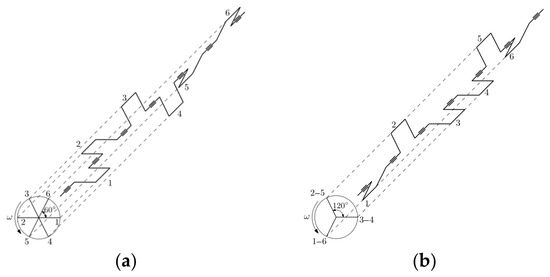
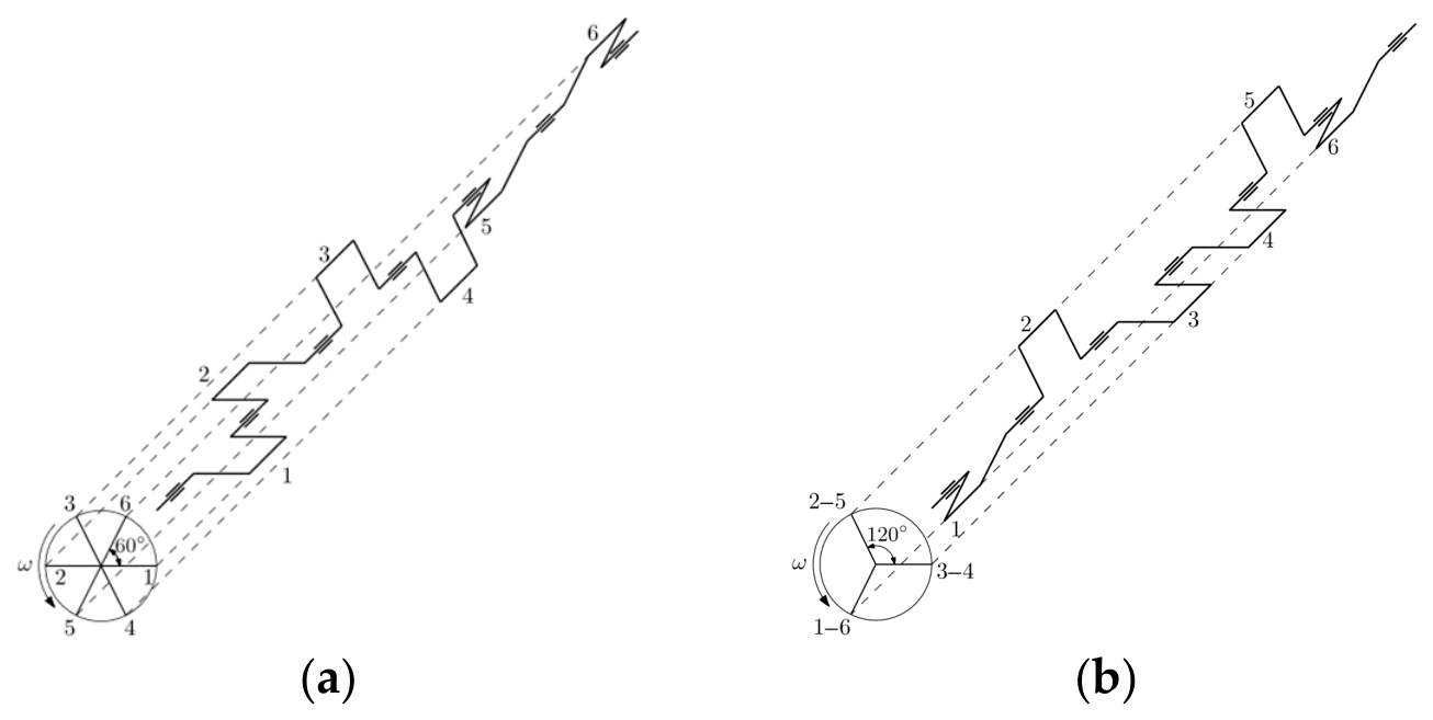
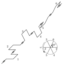
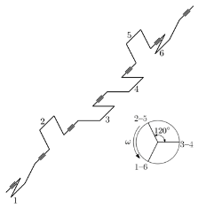
This study has focused exclusively on six-cylinder engine configurations, for which two different crankshaft geometries have been analyzed, defined by the angle between crank throws, see Figure 2. The conventional layout uses a 60° angle, which ensures a regular firing sequence and smooth torque delivery. In contrast, a configuration with a 120° angle offers natural balance but results in simultaneous combustion events, leading to a less uniform torque output.
Figure 2.
Configurations considered in the analysis. (a) six-cylinder crankshaft with a crank throw angle of 60°; (b) six-cylinder crankshaft with a crank throw angle of 120°.
Table 1 reports the imbalance values for the two configurations examined, based on the total moments and forces associated with the four components of the reciprocating forces. Since the resulting force is zero in every case, the analysis will concentrate solely on the imbalance of moments, which provides more relevant insight. Centrifugal forces are not considered here, as they can be effectively neutralized by counterweights, independently of the cylinder count of the engine or crank throw phasing.
Table 1.
Resultant forces and moments for the 6-cylinder crankshafts.
2.2.2. Direction of Rotation of the Crankshafts
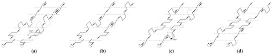
The interaction between the two crankshafts introduces a further design variable: the possibility for the imbalance of one shaft to counteract that of the other, depending on their rotational direction. One direction of the crankshaft can be fixed, while the other may rotate either in the same direction, referred to as co-rotating, or in the opposite direction, known as counter-rotating. From a fluid dynamics standpoint within the cylinders, there is no inherent limitation on the choice of rotation direction. Both configurations can be implemented by appropriately linking the crankshafts using gears, belts, or chain drives. However, the direction of rotation plays a significant role in the structural behavior and NVH (noise, vibration, and harshness) characteristics of the system. The main distinction between the two setups lies in their geometry: in co-rotating configurations, the crankshafts are identical and offset by 180° in phase, whereas in counter-rotating configurations, the crankshafts are symmetric relative to the plane perpendicular to the cylinder axes, see Figure 3. Using identical crankshafts in the co-rotating arrangement also offers practical advantages, such as lower manufacturing costs, simplified logistics, and a reduced likelihood of assembly errors during engine construction.
Figure 3.
Crankshafts layouts of all configurations. (a) six-cylinder co-rotating crankshafts with a crank throw angle of 60°; (b) six-cylinder counter-rotating crankshafts with a crank throw angle of 60°; (c) six-cylinder co-rotating crankshafts with a crank throw angle of 120°; (d) six-cylinder counter-rotating crankshafts with a crank throw angle of 120°.
2.2.3. Offset Angle Between the Two Crankshafts
The opposed-piston engine leverages piston-controlled ports and a unidirectional scavenging process, which contribute significantly to its performance advantages. The efficiency of scavenging is determined by both the shape of the ports and the phase angle between the intake and exhaust crankshafts, denoted by the symbol α (refer to Figure 4). This angle represents the phase lead of the exhaust crankshaft relative to the intake. When α is positive, the exhaust piston reaches both top and bottom dead centers before the intake piston. Since the port timing is mechanically driven by piston motion, the opening and closing of the ports are symmetric around each dead center. To initiate exhaust flow earlier in the cycle, the exhaust ports are designed to be taller than those on the intake side. If no offset is present, both sets of ports achieve full opening when the pistons reach bottom dead center, resulting in premature intake port activation and extended overlap with the exhaust ports. This overlap can cause some of the incoming charge to escape, reducing engine efficiency. By introducing a positive offset angle, the intake port timing is delayed relative to the exhaust, which helps minimize fresh charge loss and enhances trapping efficiency. However, while this improves scavenging behavior, it introduces dynamic asymmetries in the engine. The offset disrupts the alignment of inertial forces and moments between the two crankshafts, leading to imbalances in the reciprocating mass system. This phenomenon is not limited to a specific configuration but is a general consequence of phase offset in multi-crankshaft reciprocating systems. To assess the extent of this trade-off, four offset values were examined in the study: 0°, 5°, 10°, and 15°. These values were chosen based on previous research indicating that scavenging performance improves with increasing offset, reaching optimal values around 10° to 15°, beyond which the benefits plateau. In order to maintain the original combustion chamber volume while introducing an offset, the distance between the crankshafts was slightly reduced. This design adaptation allows the pistons to operate with increased proximity without risk of collision, thanks to the specific kinematics of their opposing motion.
Figure 4.
Offset angle, α, between intake (left) and exhaust (right) crankshafts; (a) co-rotating crankshafts; (b) counter-rotating crankshafts.
3. Model Description
The balancing analysis of the OP engine has been carried out using an analytical model based on the slider-crank mechanism. This model focuses on the forces generated by individual slider-crank assemblies, independent of engine architecture or cylinder count. It computes, for each crank angle, the contributions of inertial and gas forces to the crank support loads and output torque. Inertial forces have been derived analytically from crankshaft kinematics, while gas forces have been calculated using pressure profiles obtained from preliminary thermo-fluid-dynamic simulations [22]. The engine cycle has been divided into intake/exhaust, compression, combustion, and expansion phases. Polytropic relationships have been used to model compression and expansion, while combustion has been described using the Wiebe function within the first law of thermodynamics framework. To extend the model to the full engine configuration, parameters such as crankshaft offset, cylinder count, and firing order have been incorporated. Special attention has been devoted to the distinct volumetric behavior of OP engines, where two pistons move in opposite directions and can have different speeds while sharing a common combustion chamber. Unlike in conventional single-piston engines, where volume variation can be directly calculated as the product of piston stroke and bore, this configuration results in a more complex volume evolution that depends on the relative motion of both pistons. As a consequence, the in-cylinder pressure can no longer be directly mapped to the crank angle, especially when a crankshaft offset is introduced. While some prior studies (e.g., Morton [23]) assumed a fixed pressure profile referenced to one crankshaft, the present work has adopted a more rigorous approach: pressure has been expressed as a function of the instantaneous volume within the cylinder, which varies dynamically due to the offset. Fluid dynamic benefits of the offset, such as improved scavenging efficiency, have been deliberately excluded to isolate the structural impact of the offset on engine dynamics.
Engine Parameters
Table 2 summarizes the main engine parameters adopted in the model, including geometric dimensions, masses, and operating conditions. These values do not correspond to a specific engine but have been selected to represent a broad spectrum of configurations, ranging from standard passenger vehicles to high-performance designs.
Table 2.
Engine parameters.
4. Results
This section outlines the outcomes of the study. First, an investigation of engine balancing for the two configurations introduced in Section 2 is presented. For each setup, the effects of crankshaft rotation direction, co-rotating versus counter-rotating, have been explored emphasizing how crankshaft geometry influences the resulting moments and dynamic equilibrium of the engine. The role of crankshaft offset is then analyzed in both rotational scenarios, assessing its impact on system dynamics. Lastly, the effect of varying the offset angle on torque distribution is briefly addressed to assess how this parameter alters not only balance but also the partitioning of total torque between the two crankshafts.
4.1. Engine Balancing
It is straightforward to demonstrate that the crankshaft is force-balanced; therefore, this step is omitted for the sake of brevity. In contrast, the analysis of the moments acting on the two shafts is less trivial and requires closer examination.
4.1.1. Six-Cylinder with a Crank Throw Angle of 60°, Co-Rotating Layout
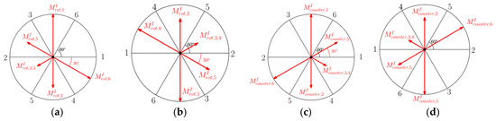
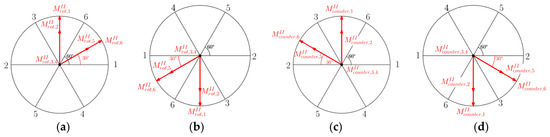
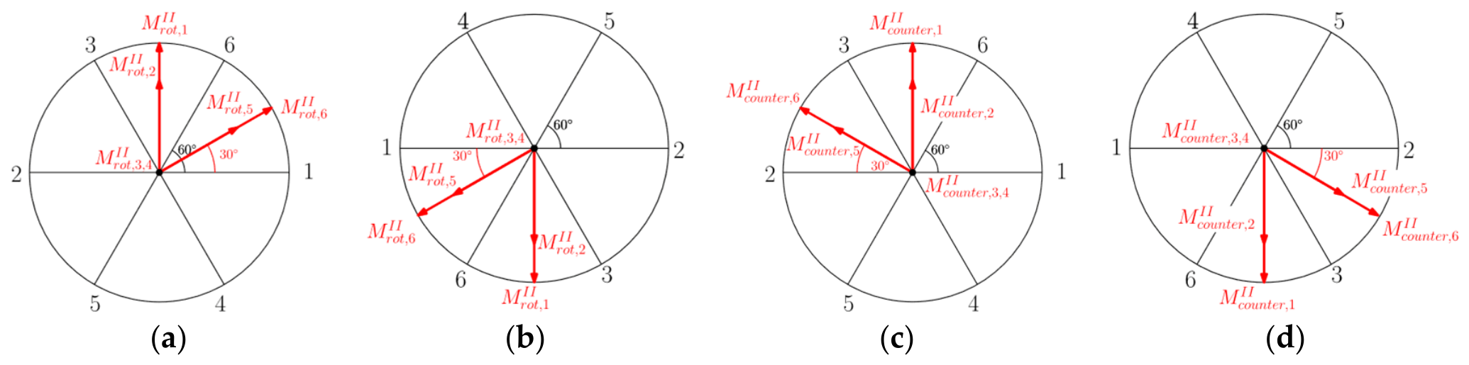
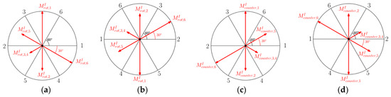
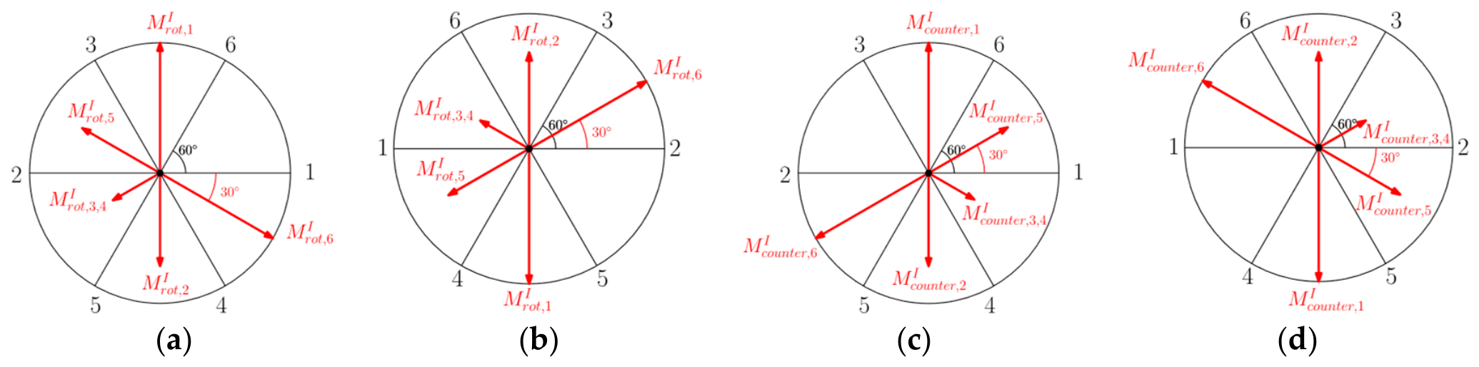
The analysis first considers the case of co-rotating crankshafts. Figure 5a–d display the moment vectors generated by first-order inertial forces from each connecting rod assembly, relative to a reference point conventionally located at the center of each shaft. Both the rotating and counter-rotating first-order moment components have a zero resultant within each individual shaft, meaning that they are fully self-balanced independently. Therefore, no further analysis is required for this order of forces. Figure 6a–d, on the other hand, illustrate the moments induced by second-order rotating and counter-rotating inertial forces. These are not balanced within each individual shaft, but they do cancel out in pairs when both shafts are considered together, specifically, Figure 6a with Figure 6b, and Figure 6c with Figure 6d. However, this cancelation is a special case that only occurs under perfect synchronization of the two crankshafts. When a phase offset is introduced between the shafts, this balance is disrupted: the offset causes the moment vectors of one shaft to rotate relative to the other, resulting in a net imbalance. This phenomenon warrants further investigation.
Figure 5.
Co-rotating shafts, crank throw angle of 60°, first-order moments. Rotating moments: (a) intake side, (b) exhaust side. Counter-rotating moments: (c) intake side, (d) exhaust side.
Figure 6.
Co-rotating shafts, crank throw angle of 60°, second-order moments. Rotating moments: (a) intake side, (b) exhaust side. Counter-rotating moments: (c) intake side, (d) exhaust side.
4.1.2. Six-Cylinder with a Crank Throw Angle of 60°, Counter-Rotating Layout
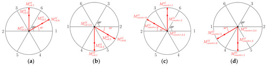
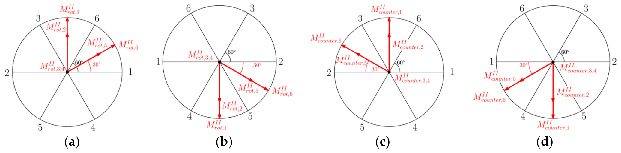
However, the behavior of the second-order components is more nuanced in the counter-rotating configuration, as shown in Figure 7a–d and Figure 8a–d. In this case, an unusual form of balance occurs: the rotating moments generated by one shaft are counteracted by the counter-rotating moments of the other. Specifically for the first-order moments, Figure 7a balances Figure 7d, and Figure 7b with Figure 7c. In addition for the second-order moments, Figure 8a balances Figure 8d, and Figure 8b balances Figure 8c. This phenomenon may appear counterintuitive at first, as the moments on the two shafts rotate in opposite directions. However, since the shafts themselves also rotate in opposite directions, the relative rotation of the second-order moments becomes aligned in space, enabling this cross-shaft cancelation. Again, it is important to note that this delicate balance only holds when there is zero phase offset between the two shafts. Once an offset is introduced, the temporal alignment of these opposing moment vectors is disrupted. As a result, the rotating and counter-rotating components no longer cancel out in time and space, leading to a net imbalance in the system. This underlines the importance of carefully analyzing the dynamic behavior of counter-rotating configurations when a crankshaft phase offset is present.
Figure 7.
Counter-rotating shafts, crank throw angle of 60°, first-order moments. Rotating moments: (a) intake side, (b) exhaust side. Counter-rotating moments: (c) intake side, (d) exhaust side.
Figure 8.
Counter-rotating shafts, crank throw angle of 60°, second-order moments. Rotating moments: (a) intake side, (b) exhaust side. Counter-rotating moments: (c) intake side, (d) exhaust side.
4.1.3. Six-Cylinder with an Angle of 120°, Co-Rotating and Counter-Rotating Layout
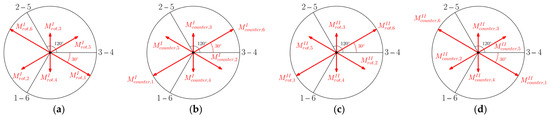
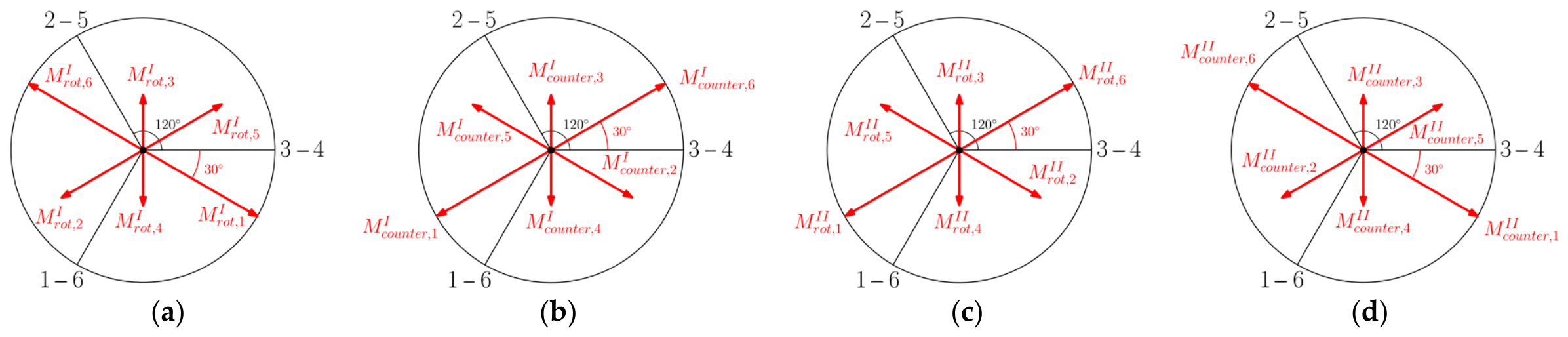
This configuration represents a simpler case compared to the previously analyzed layouts. As shown in Figure 9a–d, each individual crankshaft is inherently balanced at both first and second order. As a result, the introduction of a crankshaft phase offset does not generate any imbalance in the system. The dynamic behavior remains unaffected regardless of whether the shafts are configured in a co-rotating or counter-rotating arrangement, making this setup structurally robust and less sensitive to synchronization variations.
Figure 9.
Co-rotating and counter-rotating shafts, crank throw angle of 120°, inertial force-induced moments. Rotating moments: (a) first order rotating, (b) first order counter-rotating, (c) second order rotating, (d) second order counter-rotating.
4.2. Influence of the Offset Angle Between the Two Crankshafts
The crankshaft offset is typically introduced to enhance fluid-dynamic performance of the engine. However, this aspect is beyond the scope of the present study. Instead, the focus here is on evaluating the moment imbalance resulting from such an offset. The analysis investigates how the imbalance varies with different offset values, specifically 5°, 10°, and 15°. Only the 60° crankshaft configuration is considered, since, as shown in the previous section, the 120° layout is inherently and consistently balanced regardless of the offset.
Six-Cylinder with a Crank Throw Angle of 60°, Co-Rotating Layout and Counter-Rotating Layout
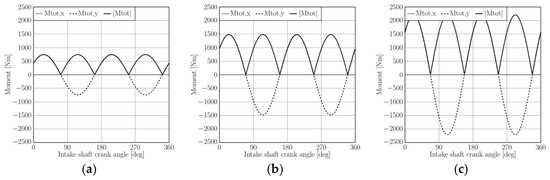
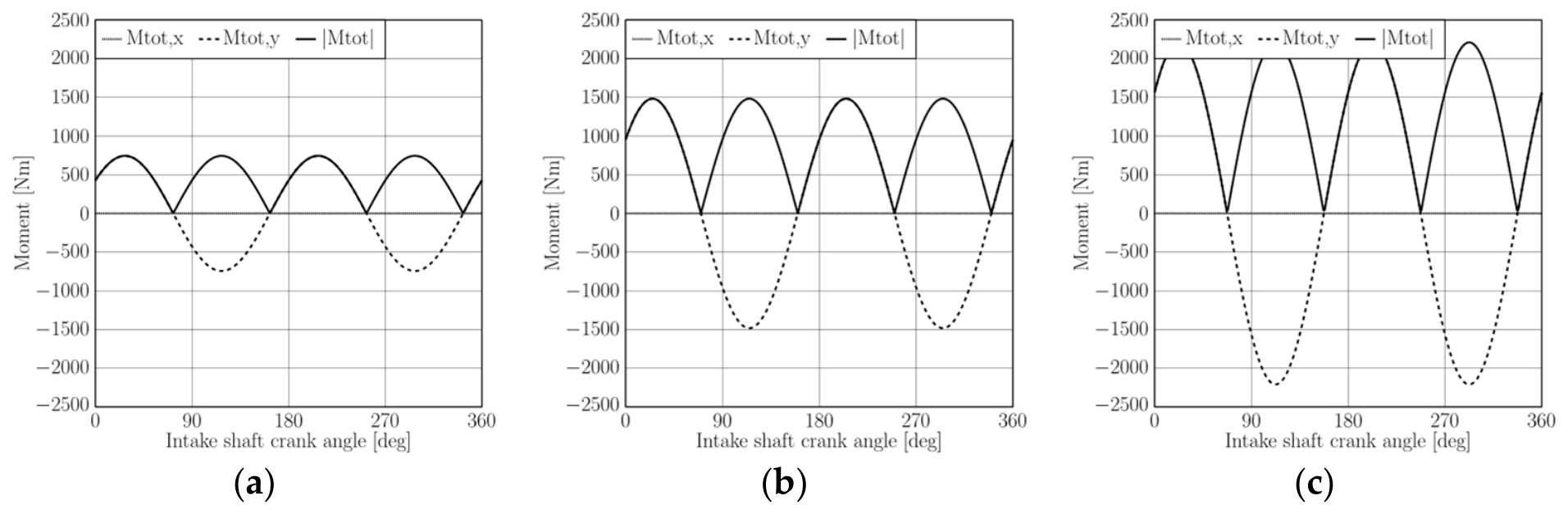
Figure 10a–c illustrate the magnitude of the imbalance across the considered offset range as a function of the crank angle of the shaft on the intake side. It can be observed that the imbalance increases with the offset angle. Notably, the resulting unbalanced moment is consistently oriented along the y-axis, which is perpendicular to the plane containing the two crankshaft axes. This observation has significant practical implications, as it can guide designers in developing appropriate frame mountings or support structures to mitigate or counteract vehicle vibration.
Figure 10.
Moment imbalanced as a function of the crank angle of the shaft on the intake side: (a) offset 5°, (b) offset 10°, (c) offset 15°.
The imbalance observed in the counter-rotating configuration is identical in both magnitude and direction to that of the co-rotating case and is therefore omitted here for the sake of brevity.
4.3. Output Torque
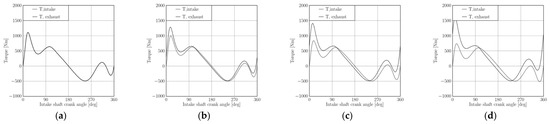
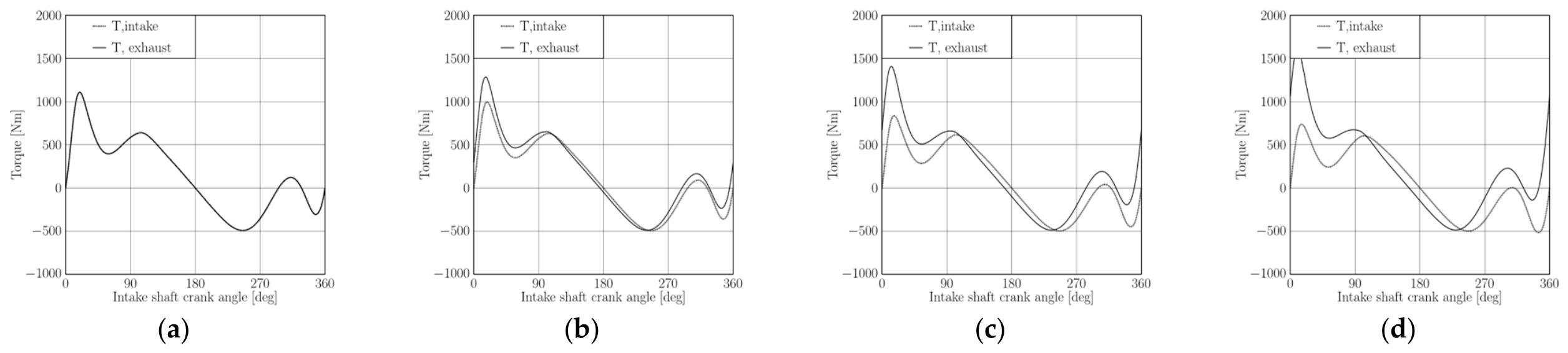
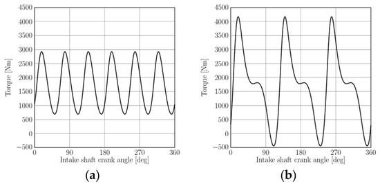
The final aspect examined in this study is the output torque delivered by the engine crankshafts. While the mean output torque remains the same across all configurations in the case of zero offset, it is crucial to analyze the instantaneous torque and its time evolution, first for a single crank mechanism, and then for the complete engine configurations previously discussed. Figure 11a–d display the instantaneous torque produced by a single crank mechanism on both the intake-side and exhaust-side shafts, evaluated across different offset angles.
Figure 11.
Instantaneous torque produced by a single crank mechanism on both the in-take-side and exhaust-side shafts: (a) offset 0°, (b) offset 5°, (c) offset 10°, (d) offset 15°.
Torque Profile of Six-Cylinder Configurations, Crank Throw Angle of 60° and 120°
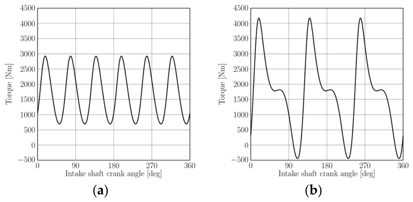
Figure 12a,b illustrate the output torque for the two crankshaft configurations with zero offset angle. A comparison of these plots clearly highlights the differences in the distribution and intensity of peaks and troughs in the instantaneous output torque.
Figure 12.
Instantaneous total torque, 0° offset: (a) six-cylinder 60° layout, (b) six-cylinder 120° layout.
5. Discussion
The results presented in the previous section can now be synthesized to provide practical guidance for engineers selecting an appropriate engine layout. In terms of crankshaft balancing, the crank throw angle of 120° configuration clearly emerges as the most favorable option, as its shafts remain perfectly balanced under all conditions, including when a phase offset is introduced. However, if it is certain that no offset will ever be applied between the two crankshafts, the 60° layout becomes equally viable, offering comparable dynamic balance. Another key factor to consider is torque smoothness. The crank throw angle of 60° configuration provides a more uniform torque delivery throughout the engine cycle, resulting in less pronounced peaks and valleys in the instantaneous output torque compared to the crank throw angle of 120° layout. Therefore, if no offset between the shafts is expected, the crank throw angle of 60° configuration is generally more suitable. On the other hand, if an offset is to be introduced, the choice becomes less straightforward, as both layouts present advantages and drawbacks that must be carefully weighed. Finally, it is important to address the relative rotation of the crankshafts. The results showed no significant differences in terms of balance or output torque between co-rotating and counter-rotating configurations. However, co-rotating layouts benefit from using two identical crankshafts, which can reduce manufacturing costs, simplify spare parts management, and minimize assembly errors. Consequently, the final choice should be guided by broader design considerations, including these practical advantages as well as the arrangement of the output shaft and power transmission system. Depending on the relative rotation of the shafts, different gear configurations or auxiliary mechanisms may still be required to match the desired direction of output rotation.
6. Conclusions
Opposed-piston engines offer a wide range of design variations and architectural choices. This study has focused on the six-cylinder configuration, which involves two crankshafts and introduces unique challenges in terms of dynamic balancing and torque distribution. Through a detailed analytical approach, the effects of crank phasing, rotation direction, and crankshaft offset were investigated. The findings highlight how specific design parameters, such as a 60° or 120° crank throw angle layout, the presence of offset, and the choice between co-rotating and counter-rotating shafts, can significantly affect the structural balance and torque regularity of the engine. These insights provide useful guidance for engineers in the early design phase, where layout decisions can have far-reaching implications on performance, vibration, and mechanical complexity. Looking ahead, a crucial next step is to analyze the mechanical system responsible for merging the torque produced by the two crankshafts and transmitting it to the gearbox. The design of the geartrain might play a key role in ensuring overall efficiency, minimizing vibration, and maintaining mechanical reliability. A deeper investigation into this subsystem is essential to complete the dynamic and structural assessment of opposed-piston engine architectures.
Author Contributions
S.G.B., A.P. and M.G. contributed equally to this work. All authors have read and agreed to the published version of the manuscript.
Funding
This research was financed by European Union-Next generation EU trough the “Piano Nazionale Di Ripresa E Resilienza (Pnrr)–Missione 4 Componente 2, “Dalla Ricerca All’impresa” Investimento 1.4, (CN00000023). In the context of the “Sustainable Mobility Center (Centro Nazionale per la Mobilità Sostenibile—CNMS)”—Spoke 12—Avviso MUR 3138/2021 modificato con DD 3175/2021.
Institutional Review Board Statement
Not applicable.
Informed Consent Statement
Not applicable.
Data Availability Statement
Data are unavailable due to confidentiality reasons.
Conflicts of Interest
The authors declare no conflicts of interest.
References
- Estevez, R.; Aguado-Deblas, L.; López-Tenllado, F.; Bautista, F.; Romero, A.; Luna, D. Internal Combustion Engines and Carbon-Neutral Fuels: A Perspective on Emission Neutrality in the European Union. Energies 2024, 17, 1172. [Google Scholar] [CrossRef] [Scilit]
- Serrano, J.R.; Novella, R.; Piqueras, P. Why the Development of Internal Combustion Engines Is Still Necessary to Fight against Global Climate Change from the Perspective of Transportation. Appl. Sci. 2019, 9, 4597. [Google Scholar] [CrossRef] [Scilit]
- Postrioti, L.; Martino, M.; Fontanesi, S.; Breda, S.; Magnani, M. Experimental and Numerical Momentum Flux Analysis of Jets from a Hydrogen Injector. In Proceedings of the SAE Technical Papers; SAE International: Warrendale, PA, USA, 2024. [Google Scholar]
- Marini, A.; Volza, A.; Baudone, A.; Mattarelli, E.; Fontanesi, S.; Di Sacco, M.; Tonelli, R.; Breda, S. Numerical Study of the Hydrogen/Air Mixing in a High Performance 2 Stroke Opposed Piston Engine. In WCX SAE World Congress Experience; SAE International: Warrendale, PA, USA, 2025. [Google Scholar]
- Volza, A.; Scrignoli, F.; Caprioli, S.; Mattarelli, E.; Rinaldini, C.A. Exploring the Potential of Hydrogen Opposed Piston Engines for Single-Cylinder Electric Generators: A Computational Study. In Proceedings of the SAE Technical Papers; SAE International: Warrendale, PA, USA, 2023. [Google Scholar]
- Madia, M.; Vaccari, M.; Dalseno, L.; Cicalese, G.; Corrigan, D.; Villa, D.; Fontanesi, S.; Breda, S. Assessment of Knock Tendency in a Hydrogen-Fuelled High-Performance Internal Combustion Engine: A Chemistry-Based Numerical Study. In Proceedings of the SAE Technical Papers; SAE International: Warrendale, PA, USA, 2025. [Google Scholar]
- Sfriso, S.; Berni, F.; Breda, S.; Fontanesi, S.; Ramalho Leite, C.; Brequigny, P.; Foucher, F. Proposal and Validation of 3D-CFD Framework for Ultra-Lean Hydrogen Combustion in ICEs. In Proceedings of the SAE Technical Papers; SAE International: Warrendale, PA, USA, 2024. [Google Scholar]
- Sfriso, S.; Berni, F.; Fontanesi, S.; d’Adamo, A.; Breda, S.; Teodosio, L.; Frigo, S.; Antonelli, M. Combination of G-Equation and Detailed Chemistry: An Application to 3D-CFD Hydrogen Combustion Simulations to Predict NOx Emissions in Reciprocating Internal Combustion Engines. Int. J. Hydrogen Energy 2024, 89, 161–176. [Google Scholar] [CrossRef] [Scilit]
- Verhelst, S.; Wallner, T. Hydrogen-Fueled Internal Combustion Engines. Prog. Energy Combust. Sci. 2009, 35, 490–527. [Google Scholar] [CrossRef] [Scilit]
- Pirault, J.-P.; Flint, M.L. Opposed Piston Engines; SAE International: Warrendale, PA, USA, 2009. [Google Scholar]
- Herold, R.E.; Wahl, M.H.; Regner, G.; Lemke, J.U.; Foster, D.E. Thermodynamic Benefits of Opposed-Piston Two-Stroke Engines. In Proceedings of the SAE Technical Papers; SAE International: Warrendale, PA, USA, 2011. [Google Scholar]
- Dagna, A.; Delprete, C.; Gastaldi, C. A General Framework for Crankshaft Balancing and Counterweight Design. Appl. Sci. 2021, 11, 8997. [Google Scholar] [CrossRef] [Scilit]
- Heifetz, M.; Marsh, M. Engine Dynamics and Balancing. In SAE International Truck and Bus Meeting and Exposition; SAE International: Warrendale, PA, USA, 1984. [Google Scholar]
- Changming, H.; Sichuan, X. The Investigation of Self-Balanced Property and Vibration on the Particular Crankshaft System for an Opposed Piston Engine. In Proceedings of the SAE Technical Papers; SAE International: Warrendale, PA, USA, 2016. [Google Scholar]
- Piergiacomi, A.; Barbieri, S.G.; Mangeruga, V.; Giacopini, M. Influence of Crank Angle Offset on the Mechanical Performance of Different Hydrogen-Fueled Opposed-Piston Engine Architectures. Appl. Sci. 2025, 15, 2537. [Google Scholar] [CrossRef] [Scilit]
- Ferrari, G. Internal Combustion Engines; Società Editrice Esculapio: Bologna, Italy, 2014. [Google Scholar]
- Barbieri, S.G.; Bianco, L.; Mangeruga, V.; Giacopini, M. A Simplified Finite Element Methodology for the Structural Assessment of an Engine Piston under Dynamic Loadings. In Proceedings of the AIP Conference Proceedings; SAE International: Warrendale, PA, USA, 2020; Volume 2309, p. 020014. [Google Scholar]
- Barbieri, S.G.; Mangeruga, V.; Giacopini, M.; Laurino, C.; Lorenzini, M. A Finite Element Numerical Methodology for the Fatigue Analysis of Cylinder Liners of a High Performance Internal Combustion Engine. Key Eng. Mater. 2019, 827, 288–293. [Google Scholar] [CrossRef] [Scilit]
- Barbieri, S.G.; Giacopini, M.; Mangeruga, V.; Bianco, L.; Mastrandrea, L.N. A Simplified Methodology for the Analysis of the Cylinder Liner Bore Distortion: Finite Element Analyses and Experimental Validations. In Proceedings of the SAE Technical Paper Series; SAE International: Warrendale, PA, USA, 2019. [Google Scholar]
- Hoag, K.; Dondlinger, B. Vehicular Engine Design; Powertrain; Springer: Vienna, Austria, 2016. [Google Scholar]
- Van Basshuysen, R.; Schaefer, F. Internal Combustion Engine Handbook Basics, Components, Systems, and Perspectives; SAE International: Warrendale, PA, USA, 2004. [Google Scholar]
- Mattarelli, E.; Caprioli, S.; Savioli, T.; Volza, A.; Di Gaetano Iftene, C.M.; Rinaldini, C.A. Virtual Development of a Single-Cylinder Hydrogen Opposed Piston Engine. Energies 2024, 17, 5262. [Google Scholar] [CrossRef] [Scilit]
- Morton, R.; Riviere, R.; Geyer, S. Understanding Limits to the Mechanical Efficiency of Opposed Piston Engines. In Proceedings of the SAE Technical Papers; SAE International: Warrendale, PA, USA, 2017. [Google Scholar]



Disclaimer/Publisher’s Note: The statements, opinions and data contained in all publications are solely those of the individual author(s) and contributor(s) and not of MDPI and/or the editor(s). MDPI and/or the editor(s) disclaim responsibility for any injury to people or property resulting from any ideas, methods, instructions or products referred to in the content. |
© 2026 by the authors. Licensee MDPI, Basel, Switzerland. This article is an open access article distributed under the terms and conditions of the Creative Commons Attribution (CC BY) license.