


Abstract
Digital twin technology is rapidly gaining traction in the semiconductor industry for its ability to model manufacturing processes, including packaging engineering, to monitor and optimise performance cost-effectively. This paper focuses on two key areas of development. The first part explores the potential of digital design and additive manufacturing to produce high-performance, compact thermal management solutions that significantly reduce device junction temperatures and enhance operational efficiency. The second part presents the development of surrogate models to predict junction temperatures of electronic packages under varying operating and geometrical conditions. These models, trained using deep learning, were integrated into a user-friendly COMSOL Multiphysics application builder version 6.3. The proposed digital twin framework enables fast and accurate full-thermal field predictions in comparison to conventional 3D finite element simulations.
1. Introduction
The increase in computing power and power density requirements in electronic components results in high thermal load and demands for advanced thermal management techniques. Additionally, there is growing pressure to reduce material usage and carbon emissions throughout the product development lifecycle.
New miniaturisation and energy-efficient solutions in semiconductor packaging are needed to meet those requirements. The current paper focuses on developing lightweight 3D components used in electronic packaging.
Thermal topology optimisation with a density-based approach is used for the simulation. The maximum volume fraction of solid metal is defined as a constraint in the optimisation study, and the average temperature of the design domain is minimised. The topology optimisation uses two main approaches. In the first approach, the solid penalisation approach [1], the solid is dispersed in the design domain, and boundary conditions are applied to the design domain boundaries. In the second approach, artificial force is applied in the fluid domain to present the solid regions where the penalisation factor is high, and flow velocity becomes zero at the solid regions [2,3].
A few studies focus on natural convection topology optimisation [4] or increasing the accuracy of two-dimensional models to match that of three-dimensional models [5]. The current investigation utilised the first approach for dispersing the metal solid material in the design domain, as it is faster to compute and requires fewer computing resources.
2. Computational Domain Description
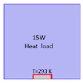
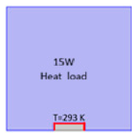
A heat source was attached to the bottom of the domain, as shown in Figure 1. The thermal properties in the design domain were correlated to the penalty factor:
Thermal Conductivity: Keff = θp × Ksolid + (1 − θp) × Kair
Density: ρeff = θp × ρsolid + (1 − θp) × ρair
Specific heat: Cpeff = θp × Cpsolid + (1 − θp) × Cpair
Figure 1.
Design space of topology optimisation model.
A constant temperature of 293 K was applied at the rectangular edges at the bottom of the design domain (100 mm × 100 mm domain size). A heat source of 15 Watt was applied to the design domain.
The inverse of thermal diffusivity is the ratio of how energy would be stored to energy conducted in the material. Usually, heat sink material has high thermal diffusivity (smaller inverse thermal diffusivity). As can be seen, Copper (Cu) and aluminium (Al) have the smallest inverse thermal diffusivity shown in Table 1.
Table 1.
Heat sink material thermal properties.
A Helmholtz filter of 1 mm was applied to control the branched fin sizing. A projection in topology optimisation with an angle β = 8 and a projection point of 0.5 was used to reduce greyscale effects and sharpen the separation between solid and liquid regions. The thermophysical properties are correlated by the penalised volume fraction instead of the material volume fraction. The penalised factor θp is correlated to the material volume fraction by [6]
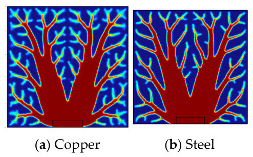
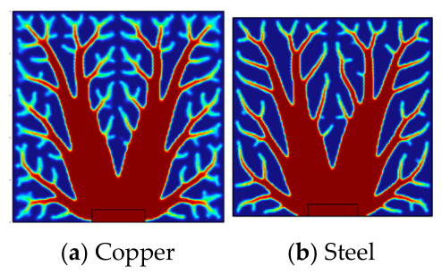
where the Psimp factor was set to 3, and θmin was set to 0.001. It can be observed that as the material diffusivity increases, there is more branching of the heat sink in the design domain when copper is compared to steel, as a sign of fast heat dispersion in the design domain material, as shown in Figure 2. It is also observed that with low diffusivity, more metal material is concentrated near the heat source base.
θp = θmin + (1 − θmin) × θPsimp
Figure 2.
Topology optimised for copper and steel.
The current copper configuration was modelled in Ansys Fluent 2025 R2 and compared to a straight fin heat sink with an air velocity of 3.5 m/s. It is observed that the optimised design configuration has 50% material reduction.
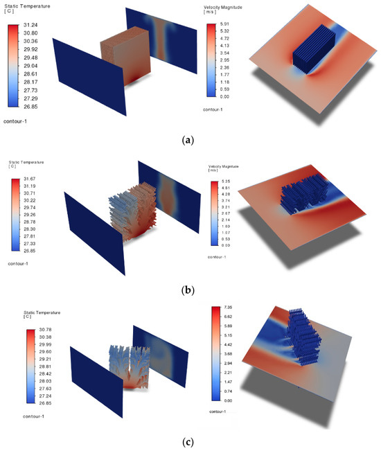
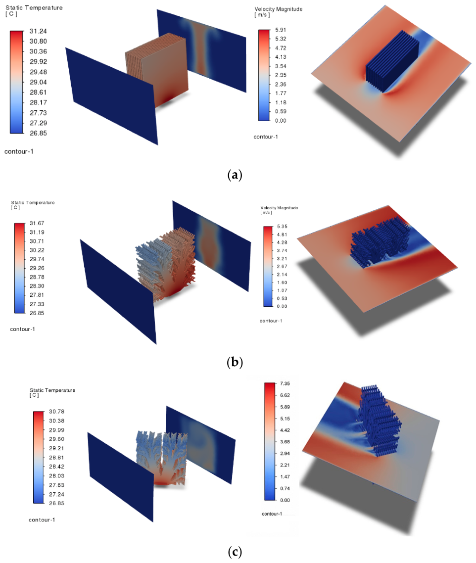
Figure 3 shows the temperature distribution; the straight fins show slightly lower resistance than the topology-optimised geometry when the air inlet is parallel to the topology-optimised fins. Three-dimensional effects in the topology-optimised geometry are inactive due to the flow separation in the heat sink front, which leads to increasing temperatures at its rear.
Figure 3.
(a) Straight fins—temperature and velocity distributions. (b) Topology optimised aligned with flow inlet—temperature and velocity distributions. (c) Topology optimised 45 degrees from the inlet—temperature distributions.
The optimised topology rotated by 45° shows low thermal resistance compared to the aligned configuration. This occurs due to the activation of 3D turbulators and inter-fin flow passes when the heat sink is rotated, as shown in Figure 3c.
3. Digital Twin of an Electronic Package
In phase two, digital twin technology enabled the rapid prediction and optimisation of thermal performance [7]. A deep learning-based surrogate model was trained using simulated data from finite element models under various operating conditions and design parameters.
Reduced-order models are another method of creating digital twin smart models; however, they have some limitations as they cannot handle geometrical parameters and can only manage operating parameters. To generate a sampling of temperature data at every location at different layers, it is recommended to perform geometry sampling at different nodes X, Y, and Z. Surrogate modelling solves this problem by creating geometry sampling using power per die, coolant inlet temperature, convective cooling heat transfer coefficient, substrate thickness, and die spacing. Data from surrogate simulations are exported for deep learning in the next stage.
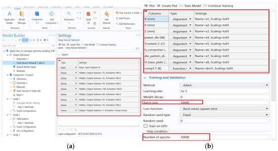
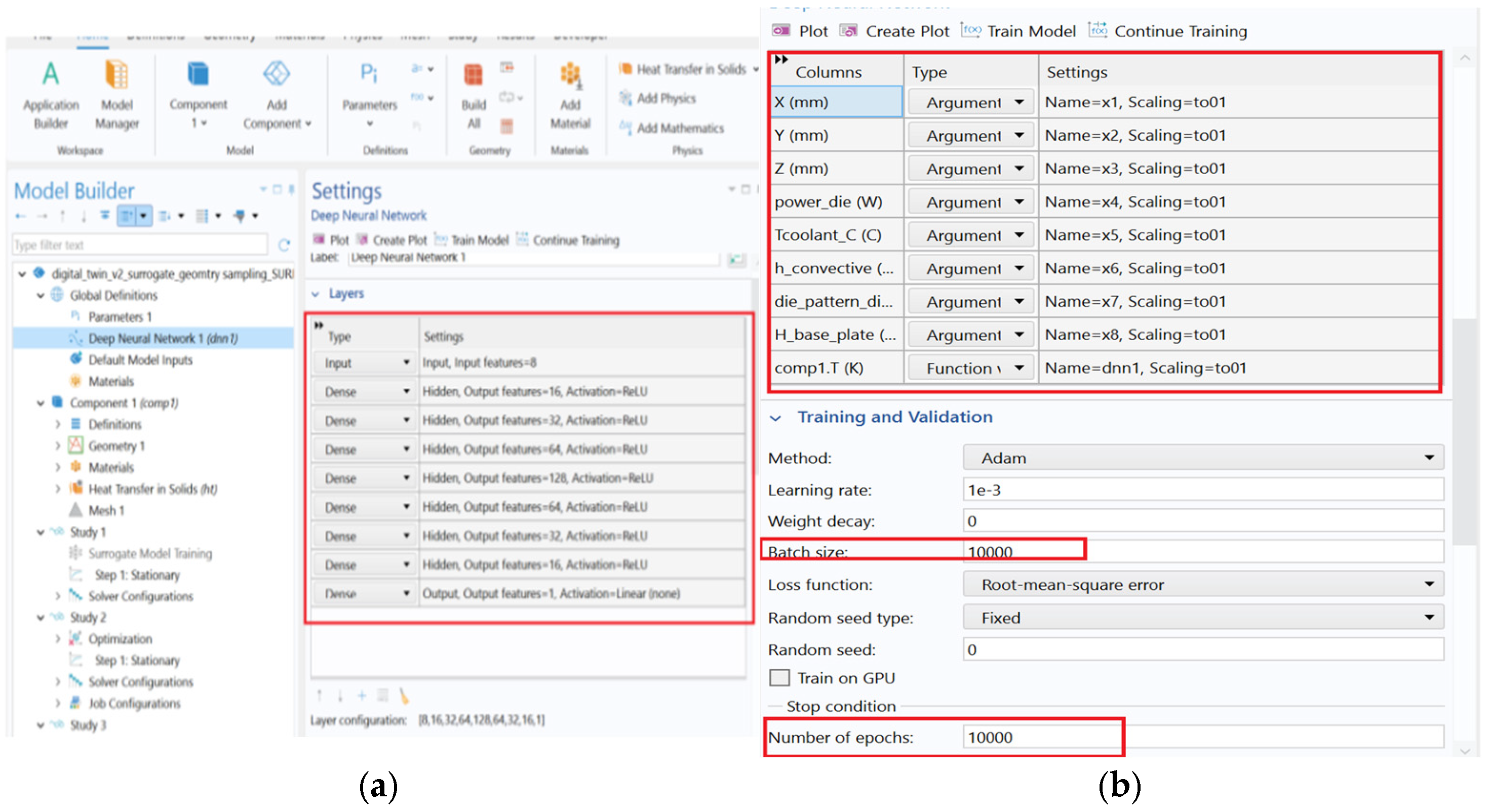
Once the model is trained, it can predict the full temperature field of the device layers. Data from the surrogate simulation are imported and scaled/normalised as shown in Figure 4. The neural network structure was defined as eight neurons in the input layer and 16 neurons, 32 neurons, 64 neurons, 128 neurons, 64 neurons, 32 neurons, 16 neurons, and one neuron at the last output layer as shown in Figure 4b. The ReLU activation function was applied during training on different layers and linear in output layer. The geometrical sampled data were trained in batches with sizes of 10,000 data point per batch with 10,000 epoches to reduce the training loss as shown in Figure 4b.
Figure 4.
Deep learning network (a) Layer structures (b) Data normalisation and selection of the number of epochs.
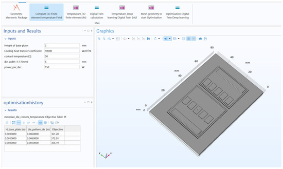
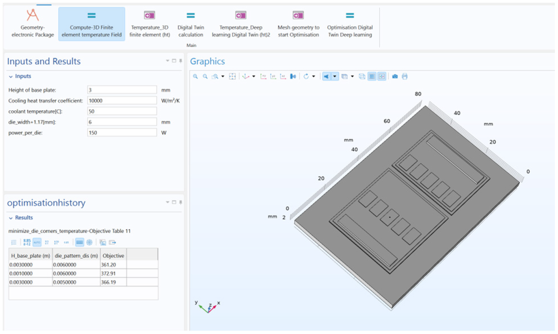
The surrogate model was embedded into a custom-built interface within COMSOL Multiphysics, version 6.3. The application Digital Twin interface enables end-users to input design parameters, and users instantly receive thermal performance feedback as shown in Figure 5. This drastically reduces the time required for design iterations compared to conventional finite element methods. Additionally, the interface includes a surrogate model optimisation feature. Designers will be able to explore trade-offs between variables such as die spacing and substrate thickness to achieve target thermal outcomes.
Figure 5.
Digital twin application interface developed to evaluate the power module.
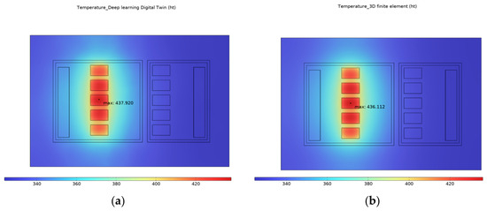
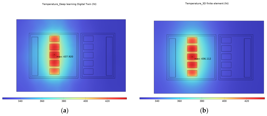
This capability aligns with the industry’s push towards digital engineering workflows, where design, simulation, and decision-making are integrated into a single platform. A comparison between fast estimations of deep learning model predictions with full finite element simulations confirms that the surrogate model provides comparable accuracy within an error margin of less than 5% as shown in Figure 6.
Figure 6.
Temperature distribution [K] from (a) deep learning digital twin model and (b) 3D finite element model.
This validates the approach as a reliable alternative for early-stage design and rapid prototyping in semiconductor packaging.
4. Design Lifecycle Analysis
Calculating the lifecycle material, energy, and carbon footprint savings from 50% copper weight reduction in a heat sink involves
Material Use Reduction: mcu,new = 0.5 × mcu,orig
Embodied Energy: Etot = mcu × EFenergy
EFenergy is the embodied energy factor for copper, usually around 23.1 MJ/kg [8].
Cradle to Gate Carbon Footprint evaluates the environmental impacts of a product from its raw material extraction (the “cradle”) to the point where it leaves the factory gate (the “gate”), i.e., when it is ready for distribution or further processing, but not yet in use by the consumer:
CFtot = mcu × EFco2
EFCO2 is the emission factor for copper production, typically 4.1 kg CO2e/kg [9]. Design lifecycle analysis results are summarised in Table 2.
Table 2.
Design lifecycle analysis.
5. Conclusions
Digital twin, topology optimisation, and additive manufacturing can enable high-performance and compact semiconductor packaging. The optimised design in this study achieved over 50% material reduction, enhancing thermal performance and environmental impact. The digital twin interface was developed using deep learning surrogate models, which achieved rapid prediction of full temperature fields and significantly accelerated the design cycle. It also supports the real-time design optimisation of the surrogate model based on user inputs, offering an effective decision-making tool for engineers. This work sets the foundation for integrating intelligent design, simulation, and manufacturing in next-generation semiconductor packaging workflows.
Author Contributions
Conceptualization, A.A. and J.C.; methodology, A.A., R.G. and J.C.; software, A.A.; validation, A.A.; formal analysis, A.A.; investigation, A.A.; resources, R.G. and J.C.; data curation, A.A.; writing—original draft preparation, A.A. and R.G.; writing—review and editing, A.A., R.G. and J.C.; visualization, A.A.; supervision, J.C.; project administration, J.C.; funding acquisition, J.C. All authors have read and agreed to the published version of the manuscript.
Funding
This research was funded by UKRI grant number UKRI240. REACT—Responsible Electronics and Circular Technologies Centre.
Institutional Review Board Statement
Not applicable.
Informed Consent Statement
Not applicable.
Data Availability Statement
The data are contained within the article.
Acknowledgments
Special thanks to Paul Jarvie and Simon Maggs for their support in the project.
Conflicts of Interest
The authors declare no conflicts of interest.
References
- Lange, F.; Hein, C.; Li, G.; Emmelmann, C. Numerical Optimization of Active Heat Sinks Considering Restrictions of Selective Laser Melting. COMSOL Conference Paper 2018. Available online: https://www.comsol.com/paper/numerical-optimization-of-active-heat-sinks-considering-restrictions-of-selective-laser-melting-63691 (accessed on 26 October 2025).
- Han, X.; Liu, H.; Xie, G.; Sang, L.; Zhou, J. Topology Optimization for Spider Web Heat Sinks for Electronic Cooling. Appl. Therm. Eng. 2021, 195, 117154. [Google Scholar] [CrossRef] [Scilit]
- Zhou, J.; Lu, M.; Zhao, Q.; Hu, D.; Qin, H.; Chen, X. Thermal Design of Microchannel Heat Sinks Using a Contour Extraction Based on Topology Optimization (CEBTO) Method. Int. J. Heat Mass Transf. 2022, 193, 122703. [Google Scholar] [CrossRef] [Scilit]
- Dong, C.-C.; He, G.; Li, D.; Zhang, Z.; Cong, J.; Meng, Z. 3D Topology Optimization Design of Air Natural Convection Heat Transfer Fins. Nucl. Eng. Des. 2024, 429, 113623. [Google Scholar] [CrossRef] [Scilit]
- Zeng, S.; Kanargi, B.; Lee, P.S. Experimental and Numerical Investigation of a Mini Channel Forced Air Heat Sink Designed by Topology Optimization. Int. J. Heat Mass Transf. 2018, 121, 663–679. [Google Scholar] [CrossRef] [Scilit]
- Jensen, K.E. Performing Topology Optimization with the Density Method. Available online: https://www.comsol.com/blogs/performing-topology-optimization-with-the-density-method (accessed on 26 October 2025).
- Zhang, K.; Qing, J.; Jin, H.; Jin, H. Digital Twin-Enabled Predictive Thermal Modeling for Stator Temperature Monitoring in Induction Motors. Electronics 2025, 14, 2814. [Google Scholar] [CrossRef] [Scilit]
- Nienborg, B.; Gschwander, S.; Munz, G.; Fröhlich, D.; Helling, T.; Horn, R.; Weinläder, H.; Klinker, F.; Schossig, P. Life Cycle Assessment of Thermal Energy Storage Materials and Components. In Proceedings of the 12th International Renewable Energy Storage Conference (IRES 2018), Düsseldorf, Germany, 13–15 March 2018. [Google Scholar]
- Mansell, G. Understand Your Copper Emissions. Available online: https://www.carbonchain.com/blog/understand-your-copper-emissions (accessed on 26 October 2025).

Disclaimer/Publisher’s Note: The statements, opinions and data contained in all publications are solely those of the individual author(s) and contributor(s) and not of MDPI and/or the editor(s). MDPI and/or the editor(s) disclaim responsibility for any injury to people or property resulting from any ideas, methods, instructions or products referred to in the content. |
© 2026 by the authors. Licensee MDPI, Basel, Switzerland. This article is an open access article distributed under the terms and conditions of the Creative Commons Attribution (CC BY) license.