1. Introduction
In recent years, there has been a rapid development of technologies related to the automation and robotization of construction processes, particularly in the field of demolition operations. Remotely controlled demolition robots are increasingly employed in tasks requiring high levels of operator safety, precision, and efficiency under harsh environmental conditions. One of the critical aspects of their design is the structural strength and fatigue durability of load-bearing systems, which are subjected to significant dynamic and time-varying loads. In such operating environments, it becomes essential not only to meet classical static strength criteria but also to provide a reliable assessment of fatigue life, which directly determines operator safety, equipment availability, and life cycle costs.
This paper presents the application of a combined numerical–experimental methodology for the structural strength analysis of load-bearing systems in remotely controlled demolition robots, with particular focus on their service durability. The research was conducted on several machines developed by Advanced Robotic Engineering ltd., representing different structural concepts of the load-bearing system. Among them, particular emphasis was placed on the largest model, ARE 3.0 [
1]. The study integrates finite element method (FEM) simulations with strain-gauge and vibroacoustic measurements to assess load paths, stress concentrations, and dynamic response under realistic operating conditions.
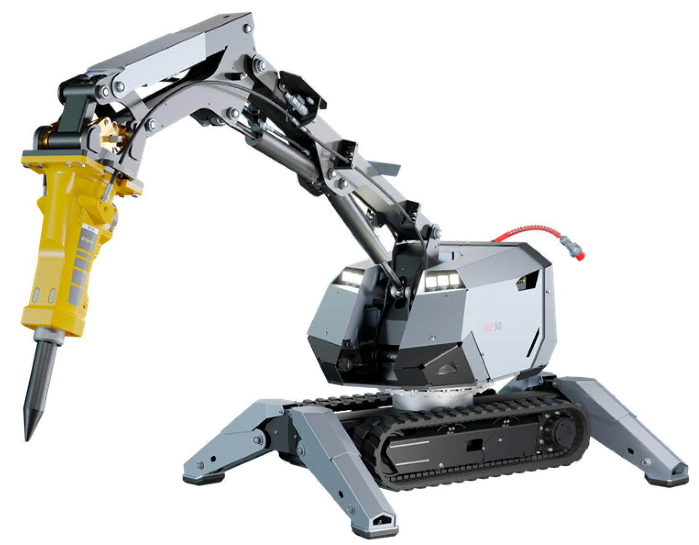
The ARE 3.0 model, presented in
Figure 1, features a split chassis configuration with a track-based undercarriage and supports that can be adjusted relative to the primary load-bearing frame. The working system, together with all drive and control subsystems, is mounted directly onto this structural frame. Such a design provides enhanced adaptability, stability, and load distribution capacity, making the machine particularly effective for heavy-duty demolition tasks in demanding environments.
In this study, a hybrid numerical–experimental methodology was employed to assess the structural integrity and fatigue durability of load-bearing systems in remotely controlled demolition robots. This integrated approach combined the predictive capabilities of computational modeling with the reliability of in situ experimental validation, enabling an accurate representation of real operating conditions. Fatigue assessment was performed using a stress–life (S–N) approach based on structural hot-spot stresses for welded joints, in accordance with EN 1993-1-9 and the recommendations of Hobbacher [
2,
3]. Time histories of stress were derived from a validated finite element (FE) model subjected to measured loads and strains acquired during representative demolition operations involving wall, ceiling, and floor removal tasks.
On the numerical side, FEM simulations were developed to evaluate stress and strain distributions under both static and quasi-dynamic load cases. Particular attention was given to simulating operational scenarios representative of demolition activities, such as impact loads, cyclic vibrations, and combined load spectra. Models incorporated material nonlinearities and boundary conditions replicating real constraints of the chassis and working arm. Iterative refinement of the mesh density and contact definitions was carried out to ensure accurate convergence of results in critical areas.
On the experimental side, strain-gauge measurements were conducted at selected hot spots identified in the FEM models, primarily at joints, welds, and support interfaces. The sensor layout was optimized to capture stress gradients and to enable correlation with numerical predictions. In parallel, vibroacoustic measurements were performed to analyze the frequency response of the structures and to detect potential resonance phenomena. Testing was carried out under laboratory conditions with loading scenarios representative of real demolition operations.
Data triangulation—linking FEM outputs with strain and vibration records—allowed for calibration of the computational models and validation of fatigue criteria. This step ensured that the models not only predicted static strength but also captured the dynamic response and durability under cyclic loading. The procedure included the identification of stress concentration zones, assessment of fatigue damage accumulation, and estimation of the residual service life of the components.
2. Research Methodology
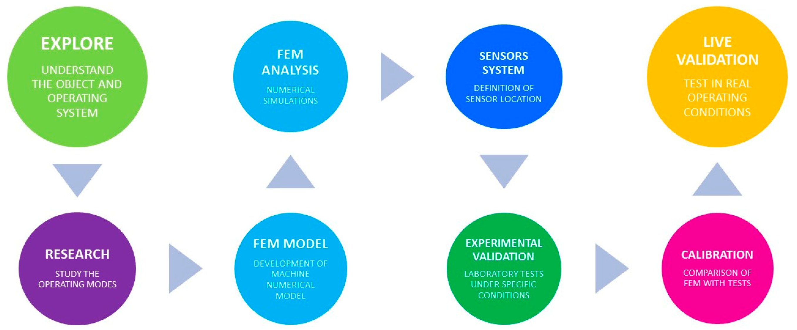
The presented methodology for Monitoring the Condition of a Remotely Controlled Demolition Robot to Prevent Structural Failures in this paper, constitutes an innovative approach that combines numerical analysis with real-time experimental measurements, developed to enhance reliability and prevent structural damage in demolition robots. The core principle of this method is the integration of computer simulations, based on the FEM, with a real-time monitoring system of loads and vibrations using strain gauges and accelerometers (
Figure 2).
FEM analysis enables the identification of local stress concentration zones and the determination of admissible stress thresholds, providing a predictive framework for detecting potential initiation sites of structural damage. At the same time, experimental measurements conducted under real operating conditions supply critical data for validating the numerical model. This model undergoes iterative calibration, allowing it to be progressively adapted to the dynamic working conditions of the machine.
A key element of the methodology is the optimization of sensor placement, supported by FEM results. This ensures efficient monitoring of critical structural components and allows for the early detection of limit states that may lead to structural degradation.
The integrated approach, combining the predictive power of numerical methods with the diagnostic value of empirical data, aligns with current trends in mechanical engineering and the concept of Digital Twins, widely applied in predictive maintenance and the design of damage-tolerant systems [
4,
5]. The validation and calibration of computational models using real measurement data is now recognized as one of the essential tools in the assessment of mechanical system reliability [
6,
7,
8].
3. FEM Analysis
In the first stage of the research, a detailed structural strength analysis of the demolition robot’s load-bearing framework is performed using the Finite Element Method (FEM). The aim of this study is to obtain a preliminary mechanical characterization of the robot’s structural system and to identify the regions most exposed to mechanical loads during real operating conditions, including environments with elevated risks of impacts and overloads typical of demolition tasks [
9,
10].
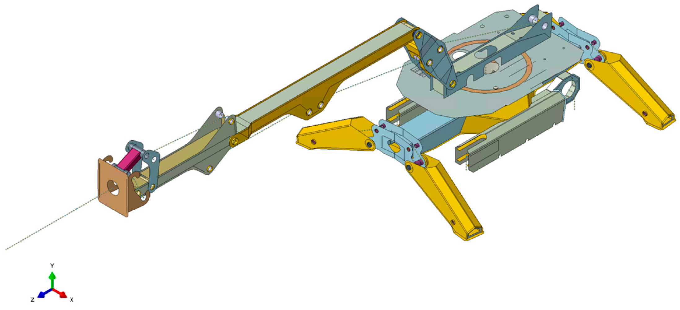
Based on the design documentation and geometric parameters, detailed numerical model is developed (
Figure 3), accurately reproducing the critical load-bearing elements of the robot. In general, these robots are subjected to load cases reflecting both typical and extreme operational scenarios, defined in accordance with data collected from operators and end-users.
The scope of the analyses includes scenarios of intensive operation of demolition tools (e.g., hydraulic hammers) as well as dynamic responses of the system resulting from external interactions and irregular contacts with the ground or the demolished structure [
11]. All tasks related to the preparation of the numerical model, as well as the computational procedures themselves, were carried out using Abaqus CAE software [
12], which enabled advanced nonlinear simulations of load-bearing components under impact and cyclic loading conditions.
Numerical analyses are carried out in three complementary stages:
Stage I—Static stress analysis.
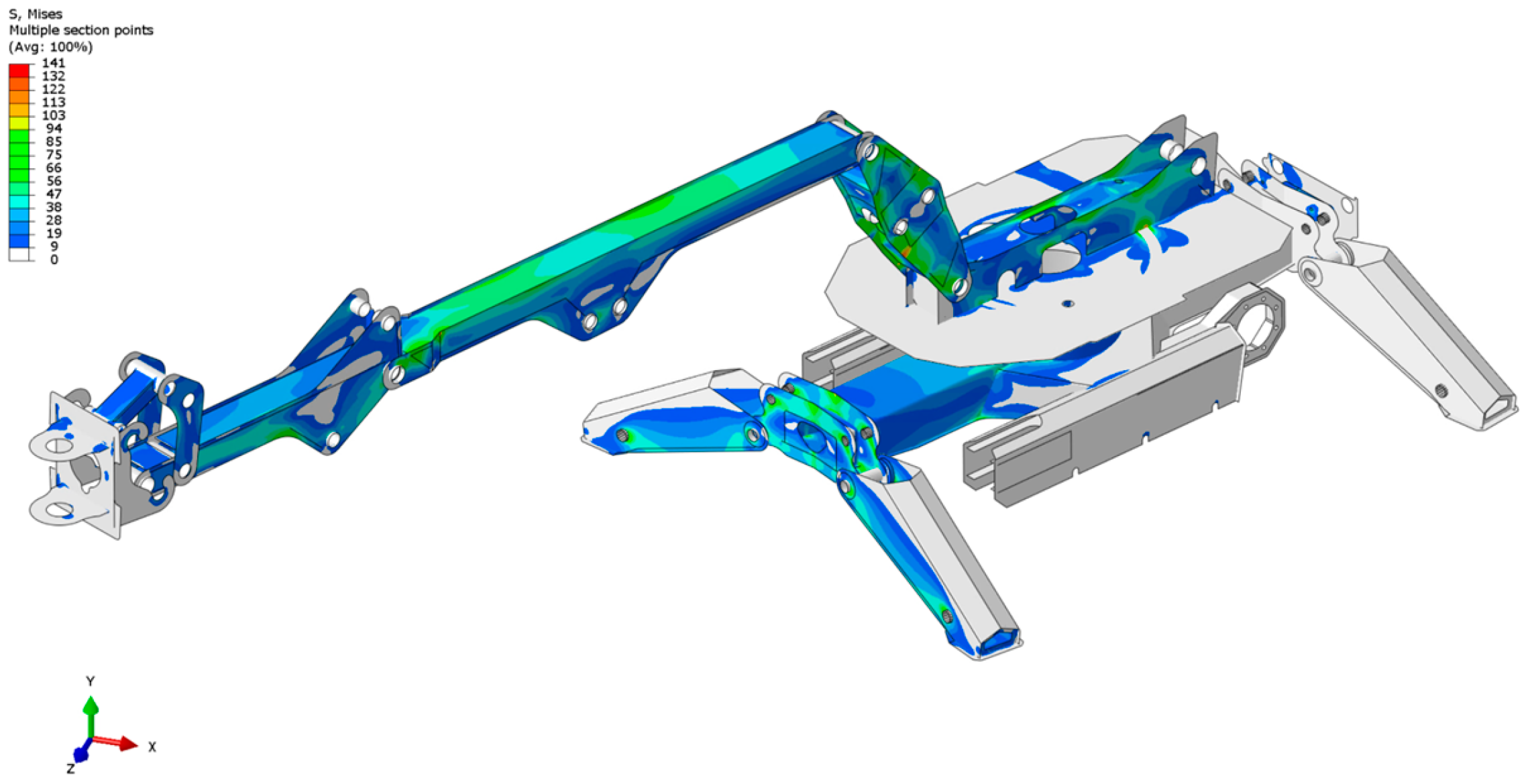
A static analysis of the equivalent stresses is performed according to the Huber–Mises–Hencky (H-M-H) hypothesis. The results are presented in the form of stress contour maps, which allow for the identification of critical zones, i.e., regions with the highest stress values and potential risk of structural failure (
Figure 4).
Stage II—Dynamic analysis.
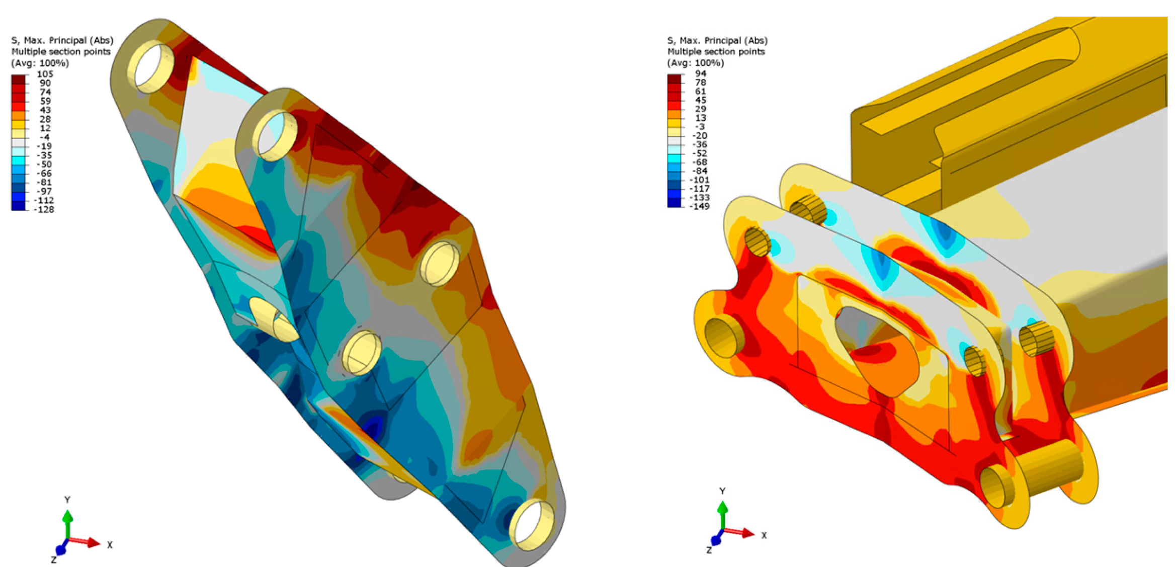
This analysis focuses on the distribution of principal stresses under variable loading conditions. The simulations reproduce the non-stationary and irregular nature of dynamic interactions typical of demolition operations.
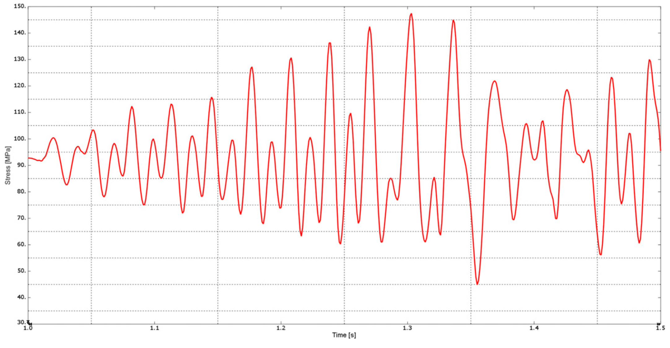
Figure 5 presents the distribution of principal stresses at a selected time step, highlighting locations of local extreme stresses under dynamic loading. The cyclic nature of stress variations was evaluated from sequences of such distributions generated over consecutive time steps, allowing identification of stress amplitudes and frequencies in critical regions. These time-dependent results were then converted into stress histories (
Figure 6), forming the basis for fatigue analysis using Rainflow cycle counting and Palmgren–Miner damage accumulation.
Figure 6 presents the temporal evolution of principal stresses for a selected point in the robot’s structure. The time-history diagram provides valuable insight into the variability of loads acting on the component during dynamic operation of the machine.
Stage III—Modal analysis.
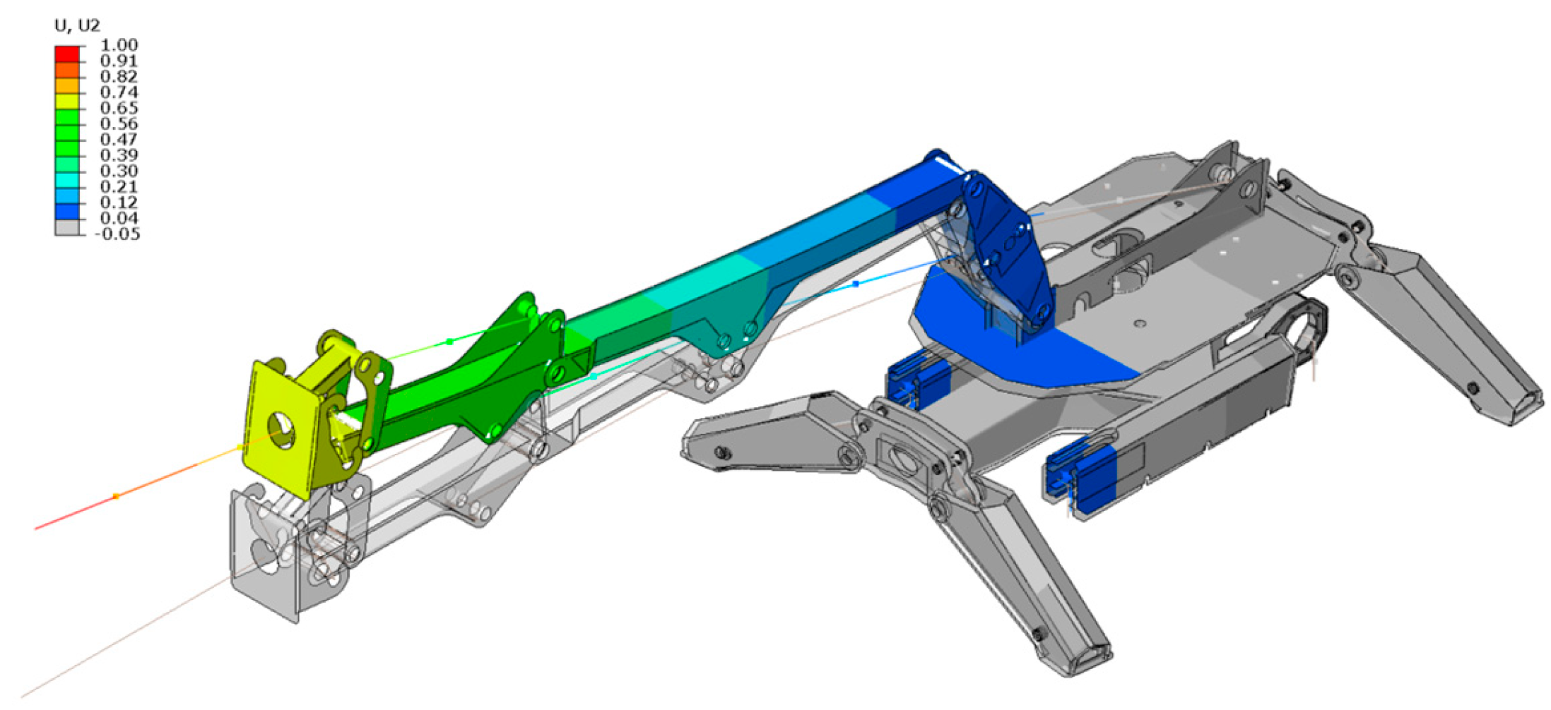
The objective of this stage is to determine the natural frequencies and mode shapes of the structure. Knowledge of natural vibration modes (
Figure 7) is crucial in the context of avoiding resonance phenomena, which could lead to excessive dynamic oscillations and, consequently, fatigue damage.
The results obtained from these three stages form the basis for subsequent experimental investigations. They are used to determine the most representative locations for installing measurement sensors, in particular strain gauges and accelerometers. Proper sensor placement ensures reliable validation of the FEM model and enables real-time monitoring of the structural behavior during operation.
4. Experimental Validation
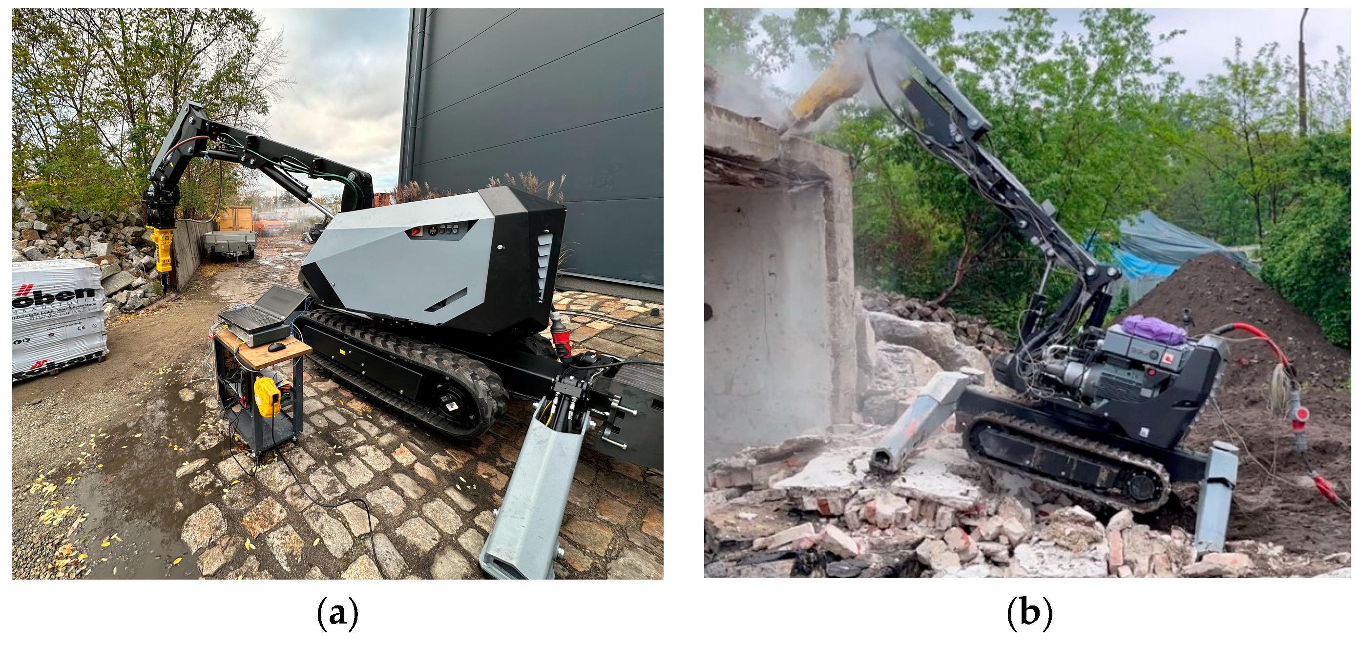
The next stage of the methodology involved experimental investigations conducted in two phases: laboratory and field testing (
Figure 8). Their main objective was to calibrate the numerical model using real measurement data and to verify FEM-predicted stress distributions against results obtained on the demolition robot ARE 3.0.
Based on FEM results—particularly equivalent (H-M-H) and principal stress maps—the most heavily loaded structural regions were identified. Strain gauges and accelerometers were installed at these critical points, typically at welds, connection interfaces, and load transfer nodes, to capture stresses representative of dominant load cases [
13,
14]. This placement strategy ensured that measurements reflected the most severe loading conditions and enabled direct validation of the FEM results.
Laboratory tests involved controlled loading conditions reproducing predefined FEM load cases. The recorded data were used for the initial calibration of the numerical model, allowing adjustment of stiffness and damping parameters to match the actual structural behavior.
The experimental investigations were also conducted during real field operations of the demolition robot, including intensive demolition activities (
Figure 8), such as chiseling reinforced concrete structures. During these tests, time histories of strain-gauge signals (
Figure 9a) and acceleration responses were continuously recorded (
Figure 9b). The data acquisition system operated with a sampling frequency of 5–10 kHz, enabling the capture of transient dynamic events and high-frequency vibration components characteristic of demolition processes.
The recorded signals were subsequently filtered and analyzed in both the time and frequency domains, allowing the identification of dominant vibration modes, impact sequences, and load cycles. This provided a detailed assessment of the structural response under dynamic operational loads and served as an additional basis for iterative validation and calibration of the numerical FEM model, ensuring its consistency with real-world operating conditions.
5. Conclusions
The proposed hybrid methodology, combining FEM-based numerical analysis with real-time experimental measurements, proved effective in assessing load conditions and identifying potential structural failure risks in demolition robots. Laboratory and field tests confirmed its potential to enhance operational efficiency and extend the structural service life.
The monitoring framework, integrating strain-gauge and accelerometer data with a dynamically calibrated FEM model, enables accurate reproduction of real operating conditions, continuous tracking of structural integrity, and predictive responses to overloads.
This integrated approach improves three key aspects of machine operation:
structural safety through early overload detection,
operational efficiency via real-time load monitoring,
component durability through optimized working conditions.
Furthermore, the integration of measurement data with FEM analysis creates the potential for developing an HMI (Human–Machine Interface) system that can actively inform the operator about unfavorable loading conditions. In this way, the system serves not only a diagnostic role but also supports operational decision-making, increasing both the functionality and reliability of the demolition robot [
15].
The presented results confirm that the integration of advanced simulation tools with real-world monitoring represents an effective solution for the development of mechanical structures designed to meet elevated strength and durability requirements.
Author Contributions
Conceptualization, D.D. and J.A.; methodology, D.D.; FEM software, J.A.; validation, D.D. and J.A.; formal analysis, D.D.; investigation, J.A.; resources, D.D.; data curation, J.A.; writing—original draft preparation, D.D.; writing—review and editing, D.D. and J.A.; visualization, J.A.; supervision, D.D.; project administration, D.D.; funding acquisition, D.D. All authors have read and agreed to the published version of the manuscript.
Funding
The article presents the results of industrial research and development works carried out within the project “Development of an innovative, multi-purpose industrial robot weighing over 3 tons, adapted for operation in industrial facilities and equipped with a novel remote-control system with operator assistance using augmented reality.” The project was implemented by Advanced Robotic Engineering Ltd. under grant no. POIR.01.01.01-00-1012/2 funded by the National Center for Research and Development, Poland.
Institutional Review Board Statement
Not applicable.
Informed Consent Statement
Not applicable.
Data Availability Statement
The data supporting the findings of this study are available from the corresponding author upon reasonable request.
Conflicts of Interest
The authors declare no conflict of interest.
Abbreviations
The following abbreviations are used in this manuscript:
| FEM | Finite element method |
| ARE | Advanced Robotic Engineering |
| HMI | Human–Machine Interface |
| H-M-H | Huber–Mises–Hencky |
References
- Advanced Robotic Engineering—Remote Controlled Demolition Robots Producer. Available online: www.arerobot.com (accessed on 10 September 2025).
- PN-EN 1993-1-9:2007/NA:2010; Eurocode 3: Design of Steel Structures—Part 1–9: Fatigue. Polish Committee for Standardization (PKN): Warsaw, Poland, 2010.
- Hobbacher, A. Recommendation for Fatigue Design of Welded Joints and Components; International Institute of Welding: Genova, Italy, 2008. [Google Scholar]
- Genta, G. Dynamics of Rotating Systems; Springer: Berlin/Heidelberg, Germany, 2005. [Google Scholar]
- Zienkiewicz, O.C.; Taylor, R.L. The Finite Element Method: Volume 1: The Basis; Butterworth-Heinemann: Oxford, UK, 2000. [Google Scholar]
- Shigley, J.E.; Mischke, C.R.; Budynas, R.G. Mechanical Engineering Design; McGraw-Hill: New York, NY, USA, 2004. [Google Scholar]
- Adams, V.; Askenazi, A. Building Better Products with Finite Element Analysis; OnWord Press: Santa Fe, NM, USA, 1999. [Google Scholar]
- Scheffer, C.; Girdhar, P. Practical Machinery Vibration Analysis and Predictive Maintenance; Elsevier: Amsterdam, The Netherlands, 2004. [Google Scholar]
- Andruszko, J.; Derlukiewicz, D. The numerical-experimental studies of stress distribution in the three-arm boom of the hybrid machine for construction works. In Proceedings of the 14th International Scientific Conference on Computer Aided Engineering; Lecture Notes in Mechanical Engineering; Rusinski, E., Pietrusiak, D., Eds.; Springer: Berlin/Heidelberg, Germany, 2019; pp. 8–14. [Google Scholar]
- Derlukiewicz, D.; Cieślak, M. Study of the Causes of Boom Elements Cracking of Electric Demolition Machine with Use of Experimental and Numerical Methods. In Proceedings of the 13th International Scientific Conference; Lecture Notes in Mechanical Engineering; Springer: Cham, Switzerland, 2016; pp. 109–119. [Google Scholar] [CrossRef]
- Derlukiewicz, D. Application of a Design and Construction Method Based on a Study of User Needs in the Prevention of Accidents Involving Operators of Demolition Robots. Appl. Sci. 2019, 9, 1500. [Google Scholar] [CrossRef]
- Smith, M. ABAQUS/Standard User’s Manual, Version 6.9; Dassault Systemes Simulia Corp: Providence, RI, USA, 2009.
- Yurdern, H.; Degirmencioglu, A.; Cakir, E. Measurement of strains induced on a three-bottom moldboard plough under load and comparisons with finite element simulations. Measurement 2019, 136, 594–602. [Google Scholar] [CrossRef]
- Sokolski, P.; Smolnicki, T. A Method for Monitoring the Technical Condition of Large-Scale Bearing Nodes in the Bodies of Machines Operating for Extended Periods of Time. Energies 2021, 14, 6637. [Google Scholar] [CrossRef]
- Kocian, M.; Pitel, J. Implementation of Human-Machine Interface for Monitoring of Operation States of Hydraulic Press. Int. J. Eng. Pedagog. 2019, 9, 134–141. [Google Scholar]
| Disclaimer/Publisher’s Note: The statements, opinions and data contained in all publications are solely those of the individual author(s) and contributor(s) and not of MDPI and/or the editor(s). MDPI and/or the editor(s) disclaim responsibility for any injury to people or property resulting from any ideas, methods, instructions or products referred to in the content. |