


Abstract
Liquid hydrogen (LH2) has been regarded as an ideal carrier for large-scale and long-distance hydrogen energy storage and transportation due to its high gravimetric hydrogen storage density, rapid refueling efficiency and favorable safety performance. However, the physical properties of LH2, such as low viscosity and high volatility at the ultra-low temperature of −253 °C, cause complex thermodynamic problems during the refueling process—including drastic phase transitions, concentrated thermal stress, and two-phase flow instability—which act as bottlenecks restricting the large-scale application of LH2. In this paper, research advances achieved domestically and internationally in recent years are reviewed in detail with respect to thermodynamic issues occurring in the ultra-low-temperature LH2 refueling process. Research achievements concerning the thermodynamics of LH2 refueling are classified, summarized and discussed from the perspectives of theoretical thermodynamic analysis, numerical simulation, experimental investigation and refueling process optimization strategies for LH2 refueling. The heat and mass transfer mechanisms involved in LH2 refueling are revealed, the variation in thermodynamic responses during the refueling process is described, the critical factors affecting the thermodynamic behaviors of LH2 refueling are clarified, the industry standards on LH2 refueling are critically assessed, and various refueling process management strategies are discussed. Finally, the future development directions of thermodynamic research on the LH2 refueling process are discussed and prospected on the basis of the development trends and potential prominent challenges faced by LH2 refueling technologies.
1. Introduction
With the aggravation of the global energy crisis and environmental pollution, the development of efficient, clean and renewable alternative energy sources has been regarded as an urgent task. Hydrogen energy is gradually recognized as the most promising high-efficiency alternative new energy due to its high energy density, environmental friendliness and abundant reserves [1,2]. Critical approaches are provided by hydrogen energy for safeguarding energy security, mitigating environmental pollution and achieving the goals of carbon peaking and carbon neutrality [3]. Three mainstream hydrogen storage technologies are currently available for industrial application: high-pressure gaseous hydrogen (GH2) storage, solid-state hydrogen storage and cryogenic liquid hydrogen (LH2) storage [4]. High-pressure GH2 storage is characterized by low cost, low energy consumption, convenient dehydrogenation and wide operating ranges and is recognized as a mature and commonly adopted hydrogen storage technology [5]. However, the gravimetric hydrogen storage density of GH2 is only 3–5 weight percent (wt%) [6], and the transportation volume is severely limited by the heavy pressure vessels, making it uneconomical for long-distance large-scale delivery [7]. Solid-state hydrogen storage is defined as a technology in which hydrogen is stored in solid materials via adsorption [8]. High volumetric storage density and superior safety are achieved by this method, while stable hydrogen absorption and release rates are maintained [9]. Furthermore, pipeline transportation is not required, and broad application prospects are anticipated. However, several limitations are encountered, such as low reversible storage capacity, sluggish absorption/desorption kinetics, and stringent temperature operating conditions [10]. Meanwhile, technical bottlenecks are widely observed in solid-state materials, including difficult hydrogenation and high encapsulation costs for hydrides [11]. As a result, the demand for continuous and rapid refueling cannot be satisfied, especially for heavy-duty vehicles and hydrogen ships. As the liquid form of hydrogen, LH2 is characterized by high gravimetric hydrogen storage density (more than 6 wt%) [12], fast refueling efficiency and low transportation cost [13]. Diversified storage and transportation modes are adopted for LH2, including fixed storage tanks with various geometric structures, LH2 tank trucks and LH2 transport ships [14]. Different requirements on transportation distance and scale can be satisfied by these modes [15]. Compared with other hydrogen storage routes, LH2 has obvious irreplaceable advantages in centralized hydrogen production, cross-regional long-distance transportation and large-scale terminal refueling and provides a feasible solution for the future large-scale development and application of hydrogen energy [16]. As shown in Table 1, the advantages and disadvantages of the hydrogen storage technologies are compared. However, an extremely low boiling point (approximately −253 °C) is possessed by LH2 under atmospheric pressure, and a large temperature difference exists between LH2 and the ambient environment [17]. Easy vaporization is experienced by LH2 during liquefaction, transportation, refueling and storage processes [18]. Therefore, an ultra-low-temperature thermal insulation environment must be maintained for LH2 throughout the industrial chain, covering hydrogen production, storage and transportation, refueling and end-use application. LH2 refueling technology is treated as a key link in the LH2 industrial chain. Storage and transportation efficiency, system safety and the economic performance of terminal applications are directly affected by this technology [19]. Meanwhile, physical and chemical properties of LH2 including density, specific heat, dynamic viscosity, thermal conductivity and latent heat of vaporization are found to be extremely sensitive to thermodynamic conditions such as pressure and temperature. Two representative inherent properties, high volatility and ultra-low viscosity, jointly lead to severe thermodynamic hazards throughout the refueling process. At atmospheric pressure, LH2 boils at −253 °C. There exists a huge temperature difference between cryogenic liquid hydrogen and warm tank walls, pipelines and ambient air. Even minor heat leakage can instantly trigger massive flash vaporization [20]. Rapid generation of hydrogen vapor compresses the gas space inside the tank, causing sharp pressure rise, overpressure risk and intensified uneven temperature stratification. The drastic gas–liquid phase transition further produces uneven thermal stress distributed on tank inner liners, threatening structural safety; the dynamic viscosity of cryogenic liquid hydrogen is far lower than conventional cryogenic media such as liquid nitrogen [21]. Low viscosity weakens viscous damping effects of fluid flow. When LH2 jets into the tank, violent liquid sloshing, irregular gas–liquid interface fluctuation and disordered two-phase turbulent flow easily occur [22]. The unstable two-phase flow breaks uniform heat exchange between the liquid and vapor phases, leading to local over-evaporation and local supercooling, which makes temperature and pressure fields inside the tank hard to predict and control. Coupled effects of flash evaporation from high volatility and unstable two-phase flow from low viscosity eventually induce complex thermodynamic problems during refueling, including drastic phase change, concentrated thermal stress and two-phase flow instability. Major bottlenecks are caused by these issues for the popularization and application of LH2 technologies [23].
Table 1.
Comparison of advantages and disadvantages of hydrogen storage technologies.
Based on whether the receiving container vents gas to the outside during the refueling process, LH2 refueling methods are classified into two types: vented refueling and no-vent fill. In the vented refueling mode, top refueling, bottom refueling (or side refueling), and angled refueling are adopted [24], as shown in Figure 1. Consequently, economic losses and safety risks are inevitably generated during the venting process. In contrast, during no-vent fill, the vent valve is kept closed throughout the process. The cryogenic gas inside the tank is not discharged, and the escape of LH2 vapor is effectively prevented. Therefore, mass loss is minimized. Due to these advantages, no-vent fill technology is widely adopted in engineering practice [25]. According to the position of the refueling inlet, no-vent fill is further divided into top, bottom, side, and angled refueling methods. Under each method, different refueling structures can be utilized to control the direction and initial state of the LH2 entering the receiving container. However, regardless of the refueling method adopted, a narrow thermodynamic window and a limited operating range are inherent to LH2. Significant variations in density and saturation pressure are observed with changes in saturation temperature. Consequently, complex and continuously changing heat and mass transfer, as well as phase transition processes, are continuously generated within the storage tank during refueling. The gas–liquid ratio and distribution, pressure distribution, temperature distribution, and velocity distribution dynamically change in real time. As a result, a series of complex thermodynamic issues are induced.
Figure 1.
Refueling mode of the LH2 storage tank refueling process: (a) top refueling; (b) bottom refueling (or side refueling); (c) angled refueling.
To address the complex thermodynamic issues during LH2 refueling, extensive scientific research has been conducted by scholars from the perspectives of theoretical analysis, numerical simulation, and experimental investigation. Although phased achievements have been obtained in the study of thermodynamic behaviors during LH2 refueling, certain difficulties still exist in the application of existing ultra-low-temperature LH2 refueling thermodynamics research to practical engineering. These difficulties are primarily caused by complex phase transitions, temperature stratification, flash evaporation effects, and sudden pressure changes. Therefore, further in-depth research is required. To promote the development of theories and methods in LH2 thermodynamics and advance the application of LH2 refueling technology in the hydrogen energy industry chain, it is considered necessary to summarize the existing research findings on ultra-low-temperature LH2 refueling processes. Through this review, the current research dynamics in the field of thermodynamics during ultra-low-temperature LH2 refueling can be better understood by readers.
At the current stage, numerous core issues are involved in the thermodynamic research of LH2 refueling processes. These issues include heat and mass transfer mechanisms, temperature and pressure variation, and refueling process optimization. Based on these considerations, a systematic review is presented in this paper, focusing on the thermodynamic characteristics of the ultra-low-temperature LH2 storage and transportation processes. The review is conducted from four aspects: theoretical analysis, numerical simulation, experimental research, and refueling processes. To comprehensively understand and optimize the LH2 refueling process, theoretical models, numerical simulations, and experimental studies have emerged as three indispensable pillars that complement one another. Theoretical models provide the fundamental physical laws and simplified mathematical frameworks necessary to capture the core thermodynamic mechanisms. Numerical simulations extend these theories to complex, multi-dimensional, and transient scenarios that are otherwise analytically intractable. Meanwhile, experimental studies offer critical empirical data for validating both theoretical assumptions and numerical predictions, while also revealing unanticipated phenomena under real-world operating conditions. The continuous feedback loop among these three approaches has been the primary driver of advancements in LH2 refueling technology. The structure of this paper is organized as follows: In Section 2, the theoretical research on the thermodynamics of the LH2 refueling process is introduced. In Section 3, the numerical simulation research on the Computational Fluid Dynamics (CFD) of LH2 refueling process is presented. In Section 4, the experimental research on the LH2 refueling process is discussed. In Section 5, the standards and management strategies for LH2 refueling are reviewed. Finally, in Section 6, the future development directions of thermodynamic research on the LH2 refueling process are explored and prospected. It should be noted that Ref. [3] is another review completed by our research team and published in the same journal and year, yet there exist fundamental differences in the research objects, core mechanisms and research boundaries between the two manuscripts, with distinct incremental innovations in this work: Ref. [3] centers on 35–70 MPa high-pressure gaseous hydrogen fast filling, while the present paper targets −253 °C cryogenic liquid hydrogen LH2 no-vent fill, two completely differentiated hydrogen storage technical routes; the dominant problem of Ref. [3] is Joule-Thomson heat accumulation and temperature rise under high-pressure gas compression; this manuscript focuses on ultra-low-temperature flash evaporation, gas–liquid two-phase instability and thermal stress induced by a huge ambient temperature difference, involving unique cryogenic phase-change heat–mass transfer rules that do not appear in Ref. [3]; the theoretical models, CFD multiphase-flow frameworks, cryogenic test platforms and boil-off loss control strategies summarized in this paper are all exclusive to liquid hydrogen and are not covered in the high-pressure gaseous hydrogen review Ref. [3]. Compared with Ref. [3], this paper fills the review blank of ultra-low-temperature liquid hydrogen refueling thermodynamics, supplements a full set of cryogenic phase-change research progress, and proposes targeted development prospects for liquid hydrogen industrialization, which forms complementary research content with Ref. [3] rather than repetitive discussion.
2. Theoretical Study on Thermodynamics of LH2 Refueling
To better understand the thermodynamic mechanisms during the refueling process, it is essential to review the fundamental properties of the working fluid. Hydrogen exists in two nuclear spin isomers: orthohydrogen and parahydrogen. At room temperature, normal hydrogen consists of approximately 75% orthohydrogen and 25% parahydrogen. However, at the liquid hydrogen boiling point (20.27 K at 1 atm), the equilibrium composition is >99.8% parahydrogen. The spontaneous conversion from ortho- to parahydrogen is exothermic, releasing significant heat (527 kJ/kg), which is comparable to the heat of vaporization (446 kJ/kg). Therefore, catalytic conversion is typically employed during liquefaction to prevent boil-off losses.
The critical point of hydrogen is a key reference for high-pressure refueling. The critical parameters are Tc = 33.19 K and Pc = 1.315 MPa. As shown in the pressure–temperature (P-T) phase diagram in Figure 2, liquid hydrogen exists in a narrow temperature range between the triple point (13.8 K) and the critical point. During the refueling process, the fluid may undergo rapid depressurization or mixing with warmer residual gas, leading to complex phase transitions. Of particular interest is the “flashing” phenomenon, where the liquid becomes superheated relative to the local pressure and undergoes rapid vaporization. Furthermore, under rapid depressurization conditions, liquid hydrogen can enter a metastable state (superheated liquid) before nucleation occurs, which significantly affects the pressure evolution inside the tank. Understanding these phase transition characteristics is vital for modeling the thermal stratification and pressure rise during no-vent fill operations.
Figure 2.
Pressure–temperature phase diagram of pure hydrogen (Adapted from Ref. [25]).
The thermodynamic analysis of LH2 refueling is mainly focused on the heat and mass transfer mechanisms and the evolution laws of parameters such as temperature and pressure. Thermodynamic models of LH2 storage containers are constructed by utilizing conservation equations. The state-change characteristics of the working fluid are obtained through solving these equations. Based on the above, the thermodynamic behaviors during the LH2 refueling process are investigated. As early as 1988, a thermodynamic model for LH2 (cryogenic propellant) refueling was first established by Chato et al. [26] from the Lewis Research Center (now Glenn Research Center) at the National Aeronautics and Space Administration (NASA). The fundamental principles of no-vent fill under microgravity conditions and the mass/energy conservation framework were elucidated. Meanwhile, sensitivity analyses were conducted on key parameters, including wall temperature, inlet liquid temperature, flow rate, and interfacial heat transfer. A theoretical foundation was laid for subsequent research on thermodynamic models of LH2 refueling. Since then, extensive theoretical research on the thermodynamics of the ultra-low-temperature LH2 refueling process has been carried out by relevant scholars.
In the early thermodynamic research on cryogenic liquid refueling processes starting from the 1980s [27], several classic theoretical models were developed based on different analytical assumptions. These models include the Fester [28], NVFill [26,29,30], GDNVF [31], NVEQU [32,33], MMCAP [34,35,36], FILL [37], LUMPY [38], and NVF [39] models. The aforementioned models have been applied to the study of thermodynamic behaviors during LH2 refueling by scholars. Based on a two-stage approach involving flash evaporation and condensation compression, the NVFill model for non-vented LH2 refueling was constructed by Chato [26,29]. Numerical calculations were carried out using the finite difference method, combined with the heat transfer laws of different injection forms. The effects of initial wall temperature, inlet flow rate, liquid temperature, interfacial heat transfer coefficient, supply pressure, and refueling structure on refueling performance were investigated. The research results indicated that the pressure rise rate in the tank was significantly affected by the initial tank wall temperature, inlet flow rate, liquid temperature, and interfacial heat transfer coefficient. Furthermore, the final liquid level was greatly influenced by the refueling structure. These research findings could provide references for refueling tests and system selection of large-scale LH2 storage tanks. According to a series of ground test results for non-vented LH2 refueling at the NASA Lewis Research Center, the prediction accuracy of the GDNVF and NVEQU models for the thermodynamic response during LH2 refueling was comparatively studied by Honkonen et al. [33]. The results showed that the tank pressure responses under most LH2 refueling conditions were well predicted by both models. However, during the initial precooling stage of the high-temperature tank walls, the predicted pressures were higher than the measured values. Nevertheless, the existing thermodynamic models for LH2 refueling mostly rely on empirical heat transfer coefficients. Consequently, poor adaptability is exhibited across different structures and operating conditions. Moreover, simplified assumptions are frequently adopted, leading to insufficient simulation accuracy for complex non-equilibrium phase transition processes. Therefore, it is necessary to construct thermodynamic models for ultra-low-temperature LH2 refueling that can balance both engineering efficiency and simulation accuracy.
To address the issues of weak universality, low computational efficiency, and poor adaptability in classic thermodynamic models for LH2 refueling, efficient and reliable lumped-parameter thermodynamic models were proposed by scholars. In these models, the phase change, interfacial heat transfer, and two-phase flow characteristics of LH2 were considered. The lumped-parameter LH2 refueling thermodynamic model is shown in Figure 3 [40], while the principles of mass and energy balance during the LH2 refueling process are illustrated in Figure 4 [41]. For the LH2 refueling process of aerospace tanks, a zero-dimensional lumped-parameter thermo-fluid coupling model was established by Gille et al. [42]. A theoretical formula for interfacial heat transfer between gas and liquid was developed. The effects of tank size and jet disturbance on the tank pressure, vapor volume, and refueling flow rate of cryogenic propellant tanks for on-orbit spacecraft were analyzed. The results indicated that the thermo-fluid lumped-parameter coupling model could effectively predict the variation in thermo-fluids inside the tank. Thus, it was suitable for the thermodynamic analysis and parameter sensitivity evaluation of non-vented cryogenic fluid refueling on orbit. Based on mass and energy conservation and non-equilibrium condensation–evaporation kinetics, a zero-dimensional lumped-parameter dynamic model for LH2 rocket propellant refueling was constructed by Osipov et al. [43]. The multiphase mass and energy exchange during the entire refueling process, especially the interfacial heat transfer and phase transition mechanisms, were investigated. The results demonstrated that the pressure and temperature evolution laws during various stages, including tank pressurization, slow filling, and fast filling, were effectively reproduced by the model. Furthermore, system obstacles were identified through the analysis of LH2 filling data. A one-dimensional lumped-parameter thermo-fluid coupling model was adopted by Hedayat et al. [44]. The thermodynamic characteristics of the storage tank in an engineering test facility during the precooling and entire refueling process were analyzed. The variation in tank pressure, tank wall temperature, and accumulated LH2 mass was explored. The results showed that the peak tank pressure met the requirements for safe operation. Moreover, the numerical calculation results agreed well with the measured data. It was concluded that the one-dimensional lumped-parameter model could effectively analyze the thermodynamic behaviors of cryogenic hydrogen storage equipment under precooling and refueling conditions. Based on the principles of mass and energy conservation, a lumped-parameter thermodynamic model was constructed by Damme et al. to simulate the LH2 refueling process of the Airbus ZEROe turboprop concept aircraft [45,46]. The refueling time and hydrogen emission loss were quantified. The effects of parameters such as refueling pressure, pipe diameter, and filling method were explored through sensitivity analysis. The results indicated that when a pipe diameter of 30 mm was adopted, the refueling time was approximately 19 min, and the emission loss accounted for about 2.2% of the total mass. These findings provided theoretical support for the design of ground operation procedures for LH2 aircraft. For the LH2 refueling process of mobile tankers, a zero-dimensional lumped-parameter thermodynamic model for the filling process of LH2 refueling vehicles was established by Yang [47]. Based on the AMESim simulation platform, a transient simulation analysis of the mobile LH2 refueling vehicle filling process was conducted. The effects of different precooling flow rates, precooling modes, and medium subcooling degrees on the filling process were investigated. The results revealed that as the precooling flow rate increased, the filling time and loss amount decreased and increased, respectively. Meanwhile, the temperature drop rate increased, and the pressure fluctuation became obvious. Under the gas–liquid precooling mode, the container temperature and pressure exhibited a gentle variation trend. This provided a reference for optimizing the mobile LH2 filling methods. Using a zero-dimensional lumped-parameter thermodynamic model for the LH2 transfer path, the boiling loss during the LH2 refueling process from a tanker to a hydrogen station tank was simulated by Petitpas et al. [48]. The effects of environmental heat transfer, initial tank pressure, and the refueling process on evaporation loss were analyzed. The results showed that the compression work of the vapor phase space in the receiving tank was the main cause of transfer loss. The loss amount was highly correlated with the initial tank pressure, while it was less related to the regulating pressure. For the refueling process of LH2 transfer pipelines, a zero-dimensional lumped dynamic thermodynamic model was built by Klopcic et al. based on the principles of mass and energy conservation [49]. The effects of pipeline status, refueling pressure difference, and tank pressure on return gas and evaporation loss were analyzed, and optimized operation schemes were proposed. The results indicated that pipeline preheating caused extremely high return gas loss. The refueling pressure difference and tank pressure affected both the loss and the refueling speed. These conclusions provided theoretical support for the design of LH2 refueling facilities and the formulation of operation strategies. Based on the Aspen HYSYS (Version 14) software, a one-dimensional lumped thermodynamic model for no-vent fill of LH2 storage tanks was built by Claussner et al. [50]. Multi-parameter sensitivity analyses were conducted on the refueling processes of aerospace LH2 tanks, stationary LH2 storage tanks, and road-mobile LH2 storage tanks. The effects of inlet conditions, heat transfer assumptions, and valve characteristics were clarified, and the thermodynamic and flow characteristics of LH2 refueling were explored. The results showed that subcooled LH2 could achieve fast and stable refueling and suppress the risks of evaporation and overpressure. Conversely, saturated LH2 was prone to generating a large amount of vapor phase and was sensitive to temperature stratification inside the tank. These results provided theoretical support for the safe and efficient operation of cryogenic LH2 infrastructure. However, the spatial non-uniformity of the fluid inside the LH2 container was ignored in the existing zero-dimensional lumped-parameter models. Consequently, the complex phase transitions and local flow details were difficult to accurately capture. Therefore, it is necessary to further resolve the spatial distribution of the thermodynamic parameters to improve the simulation accuracy of the non-equilibrium characteristics during the LH2 refueling process.
Figure 3.
Lumped-parameter LH2 refueling thermodynamic model (Adapted from Ref. [48]).
Figure 4.
Principles of mass and energy balance during the LH2 refueling process: (a) mass balance; (b) energy balance.
To simultaneously improve the calculation accuracy and operating condition adaptability of LH2 refueling thermodynamic models, multi-node thermodynamic models with layered and zoned solutions were constructed [51,52,53]. In these models, the gas–liquid interfacial mass transfer and zonal heat transfer laws were combined. For the LH2 refueling process of aerospace tanks, a 4-node model for the LH2 refueling process was established by Ma et al. [54]. The heat and mass transfer behaviors during the no-vent fill process under microgravity conditions were predicted by this model as shown in Figure 5. Furthermore, the pressure changes, refueling time, and refueling liquid level of storage tanks with different scales under various refueling conditions were obtained through the model. The results indicated that the initial tank pressure only significantly affected the pressure rise in the early stage of refueling. Additionally, the higher the initial tank temperature was, the faster the pressure rise became, and the lower the ultimate refueling liquid level was. These research conclusions could provide references for the design and control of cryogenic propellant orbital refueling. For the non-vented LH2 refueling under normal gravity and microgravity conditions, multi-node finite difference thermodynamic models were built by Li et al. [55]. Specifically, a 5-node finite difference model was used for ground conditions, and a two-node model was used for in-orbit microgravity conditions. Numerical calculations were carried out by combining various boiling heat transfer laws. The effects of parameters such as inlet liquid flow rate, initial tank wall temperature, and inlet liquid temperature were explored. Moreover, the differences in pressure and temperature changes under the two operating conditions were compared. The relevant conclusions could provide a basis for the design of in-orbit LH2 refueling systems. For the refueling process of stationary LH2 storage tanks, a 4-node thermodynamic saturation equilibrium (TSE) finite difference model was established by Wang et al. [56] for ground top-inlet non-vented cryogenic LH2 refueling. The heat transfer calculations and the assumptions of inflow and wall temperature were optimized. The research was conducted based on numerical simulations combined with experiments. The working characteristics of two top-inlet refueling structures were explored, and the variations in pressure, liquid level, and wall temperature were analyzed. Meanwhile, it was pointed out that the model had limitations after the nozzle was submerged. This provided a reference for the optimization of similar refueling systems.
Figure 5.
Heat and mass transfer behaviors during LH2 refueling process under normal and microgravity conditions: (a) ground conditions; (b) orbital conditions (Adapted from Ref. [54]).
The existing thermodynamic models for the LH2 refueling process were usually divided into two stages to analyze the entire process. These stages were the initial refueling stage (flash evaporation) and the middle-to-late refueling stage (vapor condensation and compression). The core expressions for the two stages and the heat and mass transfer analysis in the aforementioned thermodynamic models were listed in Table 2. As shown in Table 2, the theoretical framework evolves progressively from classic simplified models to lumped-parameter macroscopic models and further to refined multi-node partitioned models. This evolution effectively improves the prediction accuracy of complex thermodynamic behaviors during cryogenic LH2 refueling. Based on the thermodynamic models in the table, theoretical research on the thermodynamics of ultra-low-temperature LH2 refueling was conducted. The influence laws of parameters such as the tank wall temperature, inlet parameters, and refueling structure on the filling characteristics were clarified. These findings could support analysis and scheme optimization for scenarios including stationary LH2 refueling, mobile LH2 refueling, and aerospace LH2 refueling. However, prediction deviations still exist in some models under extreme operating conditions. Furthermore, deficiencies are found in the extrapolation and adaptability of the models under complex scenarios, and the efficiency of the analytical calculations needs to be improved. Therefore, the advantages of existing models need to be integrated into subsequent theoretical research on the thermodynamics of LH2 refueling. The theoretical assumptions and parameters are expected to be optimized, and the theoretical research is required to be expanded to multiple scenarios. Additionally, the models are supposed to be improved by combining experimental results. Ultimately, a theoretical system for LH2 refueling thermodynamics is to be constructed. This system is expected to balance accuracy and efficiency and be adapted to both complex operating conditions and various types of vehicles.
Table 2.
Core expressions of the thermodynamic model for LH2 refueling.
While lumped-parameter and one-dimensional theoretical models have successfully elucidated the fundamental thermodynamic mechanisms of LH2 refueling, they inherently rely on simplifying assumptions that limit their applicability to real-world engineering scenarios. For instance, they often struggle to capture localized flow details, complex three-dimensional geometries, and transient two-phase flow dynamics. To bridge this gap, CFD and other numerical simulation techniques are required. The theoretical models discussed in this section serve as the foundational basis for numerical simulations by providing the governing equations, thermophysical property correlations, and appropriate boundary conditions, thereby ensuring that the numerical frameworks are physically sound.
3. Numerical Simulation Research on CFD of LH2 Refueling Processes
Accurate predictions of complex thermodynamic and hydrodynamic behaviors during LH2 refueling were achieved in CFD simulation studies. Multiphysics coupling simulation models covering fluid flow, heat transfer and phase change were established in these investigations. The evolution laws of flow fields, temperature fields, pressure fields and gas–liquid phase transition throughout the entire refueling process were revealed. The physical mechanisms including flashing, heat exchange and two-phase flow during LH2 refueling were deeply understood with the help of CFD simulations. Reliable quantitative references were provided for LH2 refueling system design, process parameter optimization and safety risk assessment. With the development of cryogenic hydrogen energy technologies, CFD simulation methods were verified by numerous experimental data points. Thermodynamic behaviors in cryogenic LH2 refueling processes were accurately reproduced by these methods. The precision defects caused by simplified assumptions in theoretical models and the conditional limitations of experimental tests were compensated for. Comparative analyses of multiple parameters were completed at low costs. CFD simulation was regarded as an essential core research method in the field of LH2 refueling. CFD simulation studies for LH2 refueling were divided into two categories according to the geometric structure of refueling devices and the spatial variation characteristics of physical quantities. Two-dimensional (2D) modeling simulation and three-dimensional (3D) modeling simulation were included in the classification.
The geometric structure of the LH2 storage container was simplified in the 2D simulation model. It was projected onto a 2D plane for modeling. The physical changes in a certain spatial dimension were ignored. This model was suitable for analyzing the LH2 refueling processes with regular symmetry and uniform distribution of physical quantities in a single direction. In the research on LH2 refueling for aerospace tanks, a 34 L vertical LH2 storage tank was studied by Ma et al. [57]. A 2D volume of fluid (VOF) model was constructed based on the CFD method. The effects of the inlet structure, wall temperature, subcooling degree, and flow rate on the tank pressure, two-phase distribution, and condensation mass transfer were analyzed. The results indicated that the gas–liquid mixing was more optimal under microgravity conditions. The tank pressure changed more gently, and the refueling effect was better. The inlet structure had a weak effect on microgravity refueling. A high initial tank wall temperature caused a sudden pressure rise in the early stage of refueling. Sufficient precooling and a reasonable inlet liquid subcooling degree were found to ensure stable and efficient on-orbit refueling. A two-dimensional unsteady CFD numerical model was established by Jiang et al. [58] for the LH2 storage tank under microgravity conditions. The VOF multiphase-flow method was coupled with the Lee phase-change model. The effects of different gravitational accelerations, initial LH2 temperatures, and filling ratios on the heat transfer and phase-change characteristics inside the tank were explored. The results showed that the higher the gravitational acceleration, the stronger the convective heat transfer and the larger the evaporation amount. The higher the initial liquid temperature, the lower the temperature in the vapor-phase region. The higher the filling ratio, the lower the average fluid temperature inside the tank. In the field of stationary civil LH2 refueling research, a 2D CFD model for the transient gas–liquid two-phase flow during bottom refueling of the LH2 storage tank was established by Zhang et al. [59]. The VOF multiphase-flow model, the coupled evaporation–condensation Lee model, and the user-defined phase-change function (UDF) were utilized. The two-phase flow field distribution, temperature gradient evolution, and pressure peak characteristics inside the storage tank were investigated. The results showed that the inlet liquid temperature directly affected the intense flash evaporation intensity in the early stage of filling by regulating the pressure difference between the saturated vapor pressure and the tank pressure. An increased inlet liquid flow rate raised the pressure rise rate in the vapor-phase region at the end of filling. The final pressure level in the storage tank was determined by the initial wall temperature through its effect on the evaporation amount during the refueling process. A 2D LH2 storage tank CFD model considering conjugate heat transfer was established by Peng et al. [60] using the Lee phase-change model. The changes in thermal performance during the no-vent fill process of the LH2 storage tank under different ambient temperatures were studied. The results indicated that when the insulation layer thickness was the same, the tank pressure and heat leakage increased with the rise in the ambient temperature, and the LH2 volume fraction decreased accordingly. When the ambient temperature was the same, the internal heat of the tank decreased as the insulation layer thickness increased. When the insulation layer thickness reached 150 mm, the improvement in the insulation effect was not significant with a further increase in thickness. The heat leakage during the LH2 refueling process was effectively reduced in the LH2 storage tank combined with the vapor cooling shield (VCS). Taking a 34 L LH2 storage tank as the research object, a 2D axisymmetric CFD model was established by Li et al. [25]. The Lee model and the self-compiled UDF program were introduced to study the effects of different inlet liquid temperatures, inlet liquid flow rates, initial wall temperatures, and initial tank pressures on the no-vent fill characteristics. The results showed that the pressure in the vapor phase space of the LH2 storage tank liner increased rapidly in the early stage of refueling, then tended to be stable, and increased significantly again in the late stage. When the saturated vapor pressure corresponding to the added liquid temperature was greater than the internal pressure of the container, flash evaporation occurred in the initial refueling stage, and the pressure rise was significant in the initial stage. The inlet liquid flow rate affected the total refueling time, the vaporization pressurization in the early stage, the degree of temperature decreases in the system, and the gas hydrogen compression effect in the late stage. The initial wall temperature affected the wall boiling pressurization effect in the early stage of refueling. The initial pressure had a great impact on the pressure change in the early stage. When the initial pressure was higher than the saturated pressure of LH2, no flash evaporation occurred in the tank. In the field of mobile civil LH2 refueling research, a transient thermo-fluid CFD model was established by Kang and Yun et al. [61] based on the 2D model of the LH2 storage tank. The initial refueling process of the vehicle LH2 tank at room temperature and atmospheric pressure was numerically simulated. The focus was placed on analyzing the variation in the volume fraction, pressure, mass flow rate, and temperature inside the storage tank during the refueling process. The results showed that the LH2 evaporated intensely on the inner wall of the storage tank in the early stage of the refueling process. Subsequently, the pressure increased rapidly. In the late stage, the complex momentum generated by evaporation caused severe fluctuations in the mass flow rate at the inlet and outlet. Moreover, due to the large heat capacity and the effect of the insulation layer, the temperature drop rate of the tank wall was much slower than that of the gas region. Taking the LH2 storage cylinder as the research object, a 2D CFD model was used to conduct simulation research on the refueling process by Wang et al. [62]. The results showed that the gas–liquid interface was unstable in the early stage of refueling as shown in Figure 6a. Intense heat exchange and phase-change transformation occurred inside the storage cylinder. Obvious bubbles were observed in the liquid-phase region, and obvious secondary liquefaction was also formed in the vapor-phase region. The temperature in the vapor-phase region was almost consistent with that in the liquid-phase region as shown in Figure 6b. In the middle and late stages, the gas–liquid interface gradually stabilized. No obvious bubbles and secondary liquefaction occurred, and the temperature was gradually stratified. Based on the CFD method, a 2D axisymmetric transient model for the non-vented bottom refueling of the LH2 cylinder was constructed by Chen et al. [63]. The characteristics of the LH2 cylinder refueling process and the influence laws of key parameters were studied. The results showed that the inlet liquid flow rate was the main factor affecting the refueling pressure. For the same refueling time, the LH2 volume fraction decreased with the increase in the inlet liquid temperature. The initial pressure was negatively correlated with the LH2 filling efficiency. When the initial liquid-phase fraction increased from 0% to 40%, the final pressure increased by 15.2%, and the filling time was shortened by 38%. Based on the Ansys Fluent platform, a two-dimensional axisymmetric CFD model for the charging and discharging process of the LH2 storage tank was established by Singh et al. [64]. The VOF multiphase-flow model was coupled with the user-defined phase-change (flash evaporation, evaporation, condensation) source terms. A transient simulation of the LH2 refueling process at the inlet of the bottom radial diffuser was conducted. The focus was placed on analyzing the tank pressure rise, axial temperature distribution, and gas–liquid two-phase mass change laws during the refueling process. The results revealed the sharp pressure rise caused by flash evaporation in the early stage of refueling, as well as the competition mechanism between evaporation and condensation caused by wall heat transfer. The dominant role of the compression effect on the pressure rise at the end of refueling was clarified. A 2D axisymmetric numerical model for the vehicle LH2 cylinder including the anti-overfill device was established by Jin et al. [65] by coupling the VOF multiphase-flow model with the phase-change (evaporation/condensation) model. The effects of the throttling orifice diameter, initial liquid level, refueling rate, and initial pressure on the LH2 distribution at the end of refueling and the final filling ratio were studied. The results showed that the orifice diameter and the initial filling ratio had the greatest impact on the performance of the anti-overfill device. The final filling ratio was directly proportional to the orifice diameter and the initial filling ratio. The initial pressure had little effect on the performance of the process device. Although the 2D CFD models had advantages in computational efficiency, their simplified assumptions made it difficult to accurately capture the complex thermodynamic behaviors during the LH2 refueling process. To comprehensively analyze the dynamic evolution mechanism of the multi-dimensional flow field during the refueling process, more refined CFD models need to be constructed.
Figure 6.
Contours of LH2 liquid-phase fraction and temperature at different refueling times: (a) liquid-phase fraction contour; (b) temperature contour.
The complex geometric configurations and the spatiotemporal evolution characteristics of multi-directional physical quantities of the LH2 refueling system were restored through full-dimensional modeling technology in the 3D simulation models. These models were suitable for the refined numerical simulation of asymmetric structures, multi-field coupling, and gradient mutation scenarios during the LH2 refueling process. In the research field of LH2 refueling for aerospace tanks, a 3D VOF multiphase-flow model coupled with conjugate heat transfer was built by Pesich et al. [66]. The simulation analysis was conducted for the ground test of non-vented precooling refueling with bottom-upward jet LH2 in a 34 L storage tank. The evolution laws of the liquid level, tank pressure, tank wall temperature, gas–liquid interface evaporation/condensation mass transfer rate, and two-phase distribution throughout the entire refueling process were explored. The results indicated that the CFD model could effectively reproduce the liquid sloshing and the precooling laws of the tank wall in the early stage. However, the simulation effect for the vapor compression and pressure rise phenomenon at the end of refueling was poor. A 3D VOF multiphase-flow CFD model coupled with sloshing dynamic boundaries and the Lee phase-change model was built by Wei and Zhang [67]. Taking a 34 L bottom-inlet LH2 storage tank as the object, no-vent fill simulation analyses were carried out under normal gravity and microgravity conditions, respectively. The evolution laws of tank pressure, gas–liquid phase distribution, temperature stratification, and evaporation–condensation thermodynamic changes throughout the entire refueling process under different sloshing amplitudes and frequencies were explored. The results showed that a critical condition existed for sloshing. Below the critical value, vapor liquefaction was promoted and the tank pressure rise was suppressed. Above the critical value, the LH2 evaporation was aggravated and the pressure was significantly increased. Under microgravity conditions, the liquid spread along the tank wall and thermal stratification was weakened. The disturbance amplitude of sloshing on the tank pressure was much smaller than that in the normal gravity environment. In the field of civil LH2 refueling research, 3D refueling models for five vertical and three horizontal LH2 storage tanks (34 L) were constructed by Li et al. [24] using the Fluent (Version 2025 R1) software combined with UDFs. The refueling characteristics of different LH2 refueling methods were simulated and analyzed. The results showed that under low flow rates, the vapor space pressure of each refueling method exhibited a three-stage variation characteristic of “rapid pressure rise–stabilization–re-climbing”. As the flow rate increased, the stable refueling plateau region gradually shortened. For the vertical LH2 storage tank, the top radial refueling was more effective at a flow rate of 0.01~0.02 kg/s, while the bottom radial refueling showed obvious advantages at 0.03~0.05 kg/s. For the horizontal LH2 storage tank, the top refueling had higher efficiency at 0.01~0.02 kg/s, and the oblique-angle refueling was more effective at 0.03~0.05 kg/s. A 3D symmetric model for the vehicle LH2 cylinder was established by Jin et al. [68]. The numerical simulation of the rapid refueling process of the cylinder was carried out using the CFD method. The influence laws of the orifice diameter, refueling rate, initial filling ratio, and the volume of the anti-overfill device on the performance of the anti-overfill device were analyzed. The results indicated that the orifice diameter was the main factor affecting the performance of the anti-overfill device as shown in Figure 7. The adoption of a large-volume anti-overfill device could reserve more safe vapor space for the cylinder, but it would lead to insufficient filling volume. For the refueling process of LH2 transfer pipelines, a 3D CFD model of the LH2 refueling pipeline was utilized by Zhang and Hao et al. [69]. The heat transfer performance, temperature field distribution, heat flux density, and gas–liquid two-phase flow characteristics during the LH2 refueling process under different pipe diameters, inlet pressures, and flow velocities were studied and analyzed. The results showed that as the pipe diameter increased, the temperature rise and pressure fluctuation of the LH2 fluid were significantly suppressed, and the heat flux density was greatly reduced. Meanwhile, the significant effect of the pipe diameter on the distribution pattern of the gas–liquid two-phase flow and the phase-change heat transfer was revealed. Although the 3D CFD models performed excellently in analyzing complex geometric configurations and multi-field coupling characteristics, there were still limitations in prediction accuracy. Therefore, the algorithms needed to be further optimized to achieve the refined simulation of the full cycle of the LH2 refueling process.
Figure 7.
Contours of LH2 phase distribution and pressure distribution during filling: (a) liquid phase distribution contour; (b) pressure distribution contour (Adapted from Ref. [68]).
To systematically compare the modeling setup, accuracy and research output of existing LH2 refueling CFD works, a comprehensive comparative table is constructed in Table 3. As shown in Table 3, current CFD simulations of rapid LH2 filling can reveal the multi-physics field evolution mechanism during the charging process and achieve the quantitative analysis of key performances. They provide fluid mechanics support for the research of LH2 charging systems. However, relatively large simulation errors exist under complex working conditions. Meanwhile, the prediction accuracy is limited by insufficient full-scale measured data. In addition, refined 3D CFD simulations require large computational resources, a long calculation time and high cost. It is important to notice that many representative studies adopt the identical 34 L small vehicle tank geometry and Lee phase-change mass transfer model as the core numerical setup. Few studies carry out comparative modeling using tank volumes larger than 200 L or alternative phase-change correlation. This unified small-scale modeling scheme restricts the generalizability of simulation conclusions. The scalability to large industrial tanks remains an open critical research gap. Real industrial liquid hydrogen storage and transportation tanks range from tens to thousands of cubic meters, with drastically different length–diameter ratios, wall heat storage capacities and gas–liquid stratification characteristics compared with 34 L miniature vehicle tanks. At present, there lacks reliable verification of whether the Lee phase-change model and flow field boundary conditions calibrated on 34 L tanks can accurately reproduce the heat–mass transfer behaviors of large industrial vessels; the extrapolation error across volume scales has not been quantitatively characterized.
Table 3.
Summary of representative CFD investigations on LH2 refueling.
To sum up, the thermodynamic characteristics and influence laws of the LH2 refueling process were deeply revealed by the current CFD simulation research. The quantitative analysis of key thermodynamic performances was achieved. Important technical support was provided for the optimal design of LH2 storage and transportation systems. However, simulation errors still existed in the existing studies when complex non-equilibrium phase transitions and extreme operating conditions were handled. The prediction accuracy was highly dependent on the calibration of measured data. Furthermore, challenges such as massive computation, excessive time consumption, and high costs were faced in high-precision 3D transient simulations. Therefore, the CFD simulation methods for LH2 refueling urgently need to be improved. The simulation efficiency is expected to be optimized under the premise of ensuring calculation accuracy. In this way, the practical demands of engineering design can be better met.
Numerical simulations play a pivotal role in complementing both theoretical models and experimental studies. On one hand, they act as a virtual testing ground that allows researchers to explore a wide range of operational parameters and geometrical configurations at a fraction of the cost and time required for physical experiments. They can provide high-resolution, spatially resolved data (e.g., local temperature gradients, velocity fields, and phase distributions) that are extremely difficult to measure experimentally. On the other hand, the reliability of numerical simulations is strictly dependent on experimental validation. High-fidelity experimental data are indispensable for verifying the accuracy of turbulence models, phase-change models, and heat transfer correlations used in CFD codes. Thus, numerical simulations and experimental studies form a mutually reinforcing relationship.
4. Experimental Study of LH2 Refueling Processes
LH2 refueling experiments were regarded as a key research method to explore the thermodynamic evolution laws of LH2. The LH2 refueling operations of storage tanks were completed under temperature-controlled and closed conditions. The full-process operating conditions of actual engineering were reproduced. The dynamic variation characteristics of key parameters, such as the tank pressure, temperature, and liquid level, were accurately monitored. The influence laws of the refueling flow rate, precooling process, and liquid inlet method on the thermodynamic characteristics of the LH2 storage devices were quantitatively clarified. Meanwhile, the reliability of the thermodynamic calculations and CFD numerical simulation models was verified. These tests provided experimental support for optimizing new LH2 refueling processes and promoting the industrial application of LH2 refueling technology.
Since the 1980s, extensive and detailed experimental studies on LH2 refueling technology were conducted by NASA at the K-Site large-scale test facility of the Glenn Research Center, as shown in Figure 8 [70]. A total of 22 comparative refueling experiments were performed by Chato et al. [71] on a 2000 L LH2 tank (including 12 internal-spray-bar cases and 10 bottom-orifice cases) as shown in Figure 9a [72]. The coupled multi-field responses of the LH2 refueling process to the saturation pressure, transfer pressure difference, and initial tank wall temperature were systematically investigated [73]. It was indicated by the experimental results that the test data were in good overall agreement with the predictions of the thermodynamic equilibrium model (the average deviation was less than 3.5%). Moreover, strong parameter sensitivity was exhibited during the phase-change-dominated stage. A 34 L stainless-steel LH2 tank was studied by Moran et al. [74], and more than 40 refueling experiments were carried out as shown in Figure 9b. The effects of refueling temperature, refueling flow rate, initial tank wall temperature, and three different refueling methods on the pressure variation and final filling level were investigated. It was found that the final filling volume was negatively correlated with the initial tank wall temperature and the refueling temperature, while a positive correlation was observed with the refueling flow rate. Among the three methods, top atomized spray refueling was demonstrated to have the best overall efficiency. Furthermore, the effects of top nozzle refueling and axial spray bar refueling on the tank pressure and temperature were analyzed based on 38 LH2 refueling experiments on a 142 L tank as shown in Figure 9c. It was revealed that the pressure variations under both refueling methods could be clearly divided into three stages as shown in Figure 10: an initial rapid pressure rise, a relatively stable stage, and a final rapid pressure rise [75]. With appropriate process parameters, a filling ratio of over 90% was achieved by both methods. Cryogenic LH2 propellant transfer tests were conducted by Hartwig et al. [76] using a thin-walled, lightweight aluminum LH2 tank as shown in Figure 9d. Based on the experimental results of pressure, temperature, refueling level, and LH2 flow rate, the evolution of two-phase flow boiling and heat transfer during the refueling process was investigated. It was indicated that the average mass flow rate was increased and the refueling duration was shortened by reducing the initial pressure peak. The feasibility of the proposed rapid cooling refueling method was also confirmed. A total of 12 LH2 refueling experiments were performed by Flachbart et al. [77,78] using the 18 m3 Multipurpose Hydrogen Test Bed (MHTB) as shown in Figure 9e. It was shown by the experimental results that the short-duration filling goal of LH2 was achieved by the spray bar rapid precooling technology. Liquid accumulation was initiated immediately upon liquid entry, and the tank wall was cooled simultaneously during refueling. Film boiling was observed in the high-temperature region of the tank wall. The heat transfer was hindered by the vapor film, and consequently the cooling of the LH2 tank was significantly delayed.
Figure 8.
NASA K-Site large-scale test platform.
Figure 9.
LH2 refueling experiments in NASA K-Site large-scale test platform: (a) 2000L LH2 tank; (b) 34L LH2 tank; (c) 142L LH2 tank; (d) thin-walled, lightweight aluminum LH2 tank; (e) MHTB LH2 tank.
Figure 10.
Pressure–time curve during refueling.
The flow rate, temperature, and inlet pressure parameters during the actual LH2 refueling process were investigated by Liang et al. [79], based on two power tests of the core first and core second stages of a certain Chinese launch vehicle. It was indicated by the research results that gas–liquid two-phase flow occurred throughout the precooling stage. A steep temperature drop and significant stratification were observed, and the pressure first increased and then decreased. During the high-flow-rate refueling stage, single-phase flow was formed in the core first stage, while two-phase flow was maintained throughout the core second stage. The overall temperature rise was controlled, and the pressure varied linearly with the flow rate. In addition, refueling and transfer tests under different pressures were carried out for a 600 m LH2 transfer pipeline [80]. It was shown that the temperature rise in the pipeline under an extrusion pressure of 0.24 MPa was lower than that under 0.26 MPa. It was suggested that the transfer pressure could be appropriately reduced during the actual transfer process so that the flow velocity was closer to the optimal value. For the LH2 refueling process of LH2 carriers, cryogenic refueling experiments on a 30 L LH2 tank were conducted by Sun [81], based on the refueling module of the cryogenic liquid storage and filling experimental platform at Zhejiang Ocean University as shown in Figure 11. The pressure variation characteristics inside the LH2 tank under stationary refueling and sloshing conditions were investigated. It was found that the pressure variation trend was stable during the middle stage of refueling. Affected by the compression of the vapor space, the tank pressure increased rapidly in the later stage.
Figure 11.
Cryogenic liquid storage and filling experimental platform.
In Table 4, the comparison for existing LH2 refueling experimental campaigns is established to sort out differences in test platforms, operating windows and measured conclusions. As shown in Table 4, most experiments focus on small and medium-sized LH2 storage devices. Full-scale test data above 300 L are extremely scarce. Most studies only analyze single factors such as the initial pressure or ambient temperature, while multi-factor coupling controlled experiments are rarely reported. In addition, long-cycle repeated charge–discharge fatigue tests are insufficient, which restricts accurate evaluation of tank long-term service safety under continuous LH2 refueling cycles. From the comparison above, existing experimental data are mostly obtained under single-factor control; few platforms support synchronous adjustment of initial pressure, inlet subcooling and ambient temperature, which restricts the revelation of multi-parameter coupling thermodynamic laws.
Table 4.
Overview of typical LH2 refueling experimental facilities and test conditions.
The effects of key parameters on the tank pressure and filling efficiency were obtained by current experimental studies on LH2 refueling. These parameters included the inlet pressure, LH2 temperature, initial tank wall temperature, and refueling flow rate. However, the existing studies mainly focused on aerospace tanks. The primary data were obtained under ground conditions. Therefore, the research findings could not be directly applied to on-orbit refueling scenarios in space. Meanwhile, few studies were conducted on the LH2 refueling process for vehicle hydrogen storage cylinders, road/rail LH2 tankers, and ship hydrogen storage tanks. In particular, experimental studies on LH2 refueling technology under complex conditions (such as sloshing) were even more limited. Thus, targeted experimental studies under multiple scenarios and multiple conditions are urgently needed. These scenarios include microgravity, vehicle bumps, and ship sloshing. The coupling mechanism between multiple disturbance factors and the refueling process should be analyzed. Finally, LH2 refueling technologies adapted to different vehicles can be developed.
5. Standards and Management Strategies for LH2 Refueling
To ensure the safety of LH2 refueling operations, unify industry technical specifications, and accelerate the large-scale commercial application of hydrogen energy, relevant LH2 refueling codes and standards were formulated and published by international and national hydrogen energy technology organizations and associations [82]. LH2 refueling technology was initiated earlier in Europe and the United States. Through decades of continuous research and development and practice, a relatively complete technology and standard system was established. The three-stage LH2 refueling process was specifically designed in ISO 13984:1999 Liquid hydrogen—Land vehicle fueling system interface [83], which was published by the ISO Hydrogen Technologies Committee (ISO/TC197) in 1999 (a new version, ISO 13984:2026 Liquid hydrogen—Land vehicle fueling protocol, was released in 2026 [84]). The first stage was the pre-refueling stage, in which pipeline purging, leak testing, and pressure measurement were conducted. The second stage was the main refueling stage, in which the pipelines and the tank were cooled at a low flow rate first, and then LH2 was refueled at the target rate. The third stage was the post-refueling stage, in which the nozzle was safely disconnected after purging and leak testing were completed. In addition, the design, testing, inspection, and marking requirements for land vehicle LH2 fuel storage systems were specified in this standard. Although no specific LH2 refueling process was designed in ISO 13985:2006 Liquid hydrogen—Land vehicle fuel tanks [85], which was published in 2006, basic specifications were provided for vehicle refueling interfaces. Furthermore, a theoretical basis for safety, risk identification, and protection principles during the LH2 refueling process was provided in ISO/TR 15916:2015 Basic considerations for the safety of hydrogen systems [86], which was published by the ISO/TC 197 in 2015 (a new version, ISO/TS 15916:2026 Hydrogen technologies—Basic considerations for the safety of hydrogen systems, was released in 2026 [87]). Although the development of LH2 refueling technology in China started later, and a certain gap still existed compared with European and American countries, significant breakthroughs were achieved in recent years through technical research and industrialization demonstrations. Several national standards for LH2 were officially promulgated and implemented in 2014 and 2021. The structural dimensions and sealing forms of LH2 vehicle refueling nozzles and vehicle-mounted refueling ports were specified in GB/T 30719-2014 Liquid hydrogen land vehicle fueling system interface [88]. The process steps of pre-refueling sealing detection, docking and locking, and post-refueling pressure relief and separation were clarified. The operating temperature and cycle service life were restricted to ensure cross-equipment refueling compatibility and operational safety. The sampling and testing requirements for raw materials before refueling were clarified in GB/T 40045-2021 Fuel specification for hydrogen powered vehicles—Liquid hydrogen (LH2) [89]. The LH2 temperature and pressure conditions were restricted. The cleanliness of the medium was required to be maintained throughout the refueling process, so that safety failures such as refueling blockage, equipment corrosion, and vehicle-mounted stack failure were avoided from the fuel source. Strict purging and replacement of tanks, pipelines, and tanker systems before refueling were required in GB/T 40060-2021 Technical requirements for storage and transportation of liquid hydrogen [90]. The risk of freezing blockage and combustion explosion caused by the mixing of air and impurities was eliminated. The refueling pressure and liquid level control parameters were restricted. The closed refueling process, venting and pressure relief, and anti-static protection requirements were clarified to reduce evaporation loss and safety hazards during the ultra-low-temperature refueling process. Finally, the preconditions for LH2 refueling were regulated from the production source in GB/T 40061-2021 Technical specification for liquid hydrogen production system [91]. The automatic monitoring requirements for refueling pressure and liquid level were clarified. The processes of precooling, closed transport, and tail-gas recovery were standardized to ensure the quality of the ex-factory LH2 and the operational safety of the refueling stage. As shown in Table 5, the existing LH2 refueling codes and standards are summarized. It can be seen that ISO standards establish systematic three-stage filling procedures and universal safety principles for liquid hydrogen refueling. Chinese national standards focus on engineering implementation, specifying interface structure, medium cleanliness and purge operation requirements. For future large-scale liquid hydrogen demonstration projects, continuous integration and updating of standard systems are required.
Table 5.
Overview of existing LH2 refueling codes and standards.
Although LH2 refueling processes were designed and specified in existing standards and codes, the extremely low temperature of LH2 caused a large temperature difference between the LH2 and the warm tank surface during the refueling process. Consequently, LH2 evaporation loss was always present. Although boil-off gas recovery methods could be used to capture the evaporated gas, additional costs were incurred and system complexity was increased. Therefore, the LH2 refueling process needed to be optimized, and effective refueling control strategies were implemented. Currently, the optimization strategies for the LH2 refueling process mainly included precooling, refueling rate optimization, and multi-stage temperature/pressure control. In terms of LH2 refueling precooling technology, a numerical model for the thermal balance of the entire precooling process was established by Zhang and Ma et al. [92]. The charge–hold–vent (CHV) precooling characteristics of cryogenic propellant tanks under microgravity conditions were investigated. The effects of mass flow rate, vent target pressure, and the minimum limit of gas-wall temperature difference on precooling performance were analyzed. It was indicated that the cooling capacity of cryogenic fluid was insufficiently utilized in the early stage of CHV precooling, and overpressure risks were easily triggered. The wall cooling rate gradually decreased during the charge, hold, and vent stages of the CHV precooling cycle. Boiling heat transfer between the liquid and wall mainly occurred during the charge stage, and film-boiling heat transfer dominated throughout this stage. It was demonstrated that CHV precooling performance could be effectively improved by appropriately increasing the mass flow rate and the gas–wall temperature difference limit. The precooling duration was reduced by 38%, and the consumed mass was only increased by 10%. A 2000 m3 LH2 spherical tank was taken as the research object by Jin et al. [93]. A three-dimensional numerical model was established, and CFD methods were used to simulate the refueling precooling process. The effects of precooling medium types, spray ring structures, and outlet positions were analyzed, and the precooling effects of two spray ring structures were compared and presented Figure 12. It was shown that the asymmetric flow field formed during liquid nitrogen precooling could accelerate the cooling of the high-temperature regions on the wall and suppress local overheating. Through spatial stratification design, the double-layer spray ring structure increased the nozzle spacing and reduced the mutual interference between LH2 evaporation gases. Thus, precooling uniformity was improved. Furthermore, Okpeke et al. studied the effectiveness of liquid nitrogen and liquid helium precooling through comparing the filling processes of LH2 tanks with and without precooling [94]. The evaporation loss of LH2, the cost of the precooling process, and the economic feasibility of the precooling process were evaluated. It was found that evaporation loss could be significantly reduced by precooling technology. LH2 evaporation loss could be better reduced if the tank was made of AL5083-O material. Liquid nitrogen precooling was characterized by low cost and high economic feasibility. The internal temperature distribution of the tank, the dynamic characteristics of hydrogen evaporation loss during the filling process, as well as the mass flow rate and time factors, were required to be considered in the precooling process. A one-dimensional prediction model for the precooling process of large-scale LH2 pipelines was established by Lu [95], and the pipeline precooling performance was studied. A staged precooling scheme suitable for large-diameter LH2 transfer pipelines was designed. It was revealed that the temperature of the LH2 pipeline decreased gently during the gas cooling stage, and the cooling rate first increased and then decreased during the liquid cooling stage. Pulsating dynamic changes in pipeline pressure were observed during the precooling process. These results could provide theoretical support for high-efficiency precooling technology for long-distance LH2 transportation. To understand the mechanism of cryogenic fluid precooling and transfer, the variations in performance parameters for cryogenic refueling equipment and fluids are analyzed. Based on the multi-disciplinary simulation platform AMESim (Version 2504), a liquid hydrogen refueling mechanism model is established by Fu et al. [96]. Heat transfer, temperature and pressure variations during precooling and refueling processes were simulated and analyzed. A feasible scheme for optimizing the liquid hydrogen refueling procedure was proposed, which included increasing tank pressure and adding exhaust ports during the precooling stage. With the above scheme, the precooling rate can be effectively improved, and the precooling duration can be reduced by 50%. Regarding the process optimization of LH2 refueling rate, the LH2 flow rate regulation scheme was improved by Zhang [97] based on the third-stage LH2 refueling test results of a rocket. The effect of the improved scheme was evaluated through numerical comparative analysis. It was indicated that the LH2 refueling time could be effectively controlled, and LH2 quality could be improved by using a throttle valve for low-flow-rate refueling. Accurate and timely LH2 replenishment before rocket launch was achieved.
Figure 12.
Temperature distribution of LH2 spherical tank at different moments under different precooling media: (a) liquid nitrogen precooling; (b) liquid hydrogen precooling.
For the multi-stage temperature/pressure control methods in LH2 refueling, the optimization ideas for the LH2 refueling process were proposed based on the characteristics of LH2 tank refueling and thermal stress by Geng [98]. A high liquid inlet flow rate was prioritized to achieve short-duration refueling. The flash vaporization pressurization effect at the initial stage of refueling was controlled by appropriately reducing the liquid inlet temperature and/or increasing the initial pressure. The vaporization pressurization effect at the initial stage of refueling was weakened by appropriately reducing the initial wall temperature. In addition, different LH2 refueling management strategies are compared in Table 6. Precooling offers stable temperature control as the mainstream industrial method, yet it raises energy consumption and equipment costs. Refueling rate optimization saves energy without extra cooling equipment, but it requires high-precision real-time control. Multi-stage temperature/pressure control improves hydrogen utilization at the cost of complex systems. For large-scale heavy-duty applications, precooling integrated with multi-stage filling is more suitable.
Table 6.
Comparison of LH2 refueling management strategies.
Existing standards and management strategies for LH2 refueling processes were effective in regulating refueling operations and preventing safety risks. However, several issues were identified. The standard system was incomplete, the precision of control was insufficient, the adaptability to complex operating conditions was weak, and the operation and maintenance costs were high. These problems restricted the large-scale application of the technology. Therefore, technologies such as artificial intelligence and automatic control are necessary to integrate. A LH2 refueling management scheme with unified standards, precise control, and controllable costs should be constructed. Support is thus provided for the large-scale application of LH2 refueling technology.
6. Research Prospects for LH2 Refueling
As a critical link in the storage and transportation of future clean energy, thermodynamic research on LH2 refueling technology has evolved from single-physical-field analysis to multi-field coupling analysis and from qualitative description to quantitative prediction. Although existing studies have explored phase-change heat transfer, flashing pressure relief, and cold energy loss during LH2 refueling, obvious deficiencies still restrict the large-scale application of LH2 refueling technology. Further in-depth research can be conducted from the following perspectives:
- (1)
- Heat and mass transfer laws of LH2 refueling under conventional operating conditions can be described by existing thermodynamic models. However, they are constrained by hydrogen storage vessel structures, thermal insulation performance, ambient heat exchange, refueling flow rates and other factors; universal thermodynamic models applicable to various types of hydrogen storage equipment have not been established. A variety of variables, including structural geometric parameters, thermophysical properties of thermal insulation materials, and operational parameters, need to be comprehensively integrated. A unified thermodynamic theoretical model for the whole LH2 refueling process should be constructed to accurately characterize the dynamic evolution of temperature, pressure, gas–liquid phase transition, and filling capacity during refueling.
- (2)
- Two-phase flow and heat transfer processes inside storage vessels can be reproduced by current CFD simulation models for LH2 refueling. Nevertheless, the thermophysical parameters of hydrogen fluids exhibit significant nonlinear characteristics under cryogenic conditions. While established thermophysical databases such as NIST REFPROP provide highly accurate fundamental property data for parahydrogen [99,100], their applicability to the complex operating conditions encountered during LH2 no-vent fill remains limited, including accurately modeling ultra-low-temperature two-phase flow behavior and real-gas effects under rapid depressurization scenarios. Fine-scale two-phase flow simulations require extensive computational time, making it difficult to balance calculation accuracy and computational efficiency. In addition, existing CFD studies lack multi-scale validation for industrial tanks of tens to thousands of cubic meters, making it difficult to quantify the extrapolation errors across volume scales. In future studies, high-precision algorithms adapted to the equations of state of LH2 in supercritical, subcritical, and two-phase regions should be developed. Machine learning and deep learning technologies can be introduced to establish data-driven CFD models and develop modified phase-change correlations suitable for large-volume vessels [101]. Computational costs can be greatly reduced while calculation accuracy is guaranteed. An efficient and reliable intelligent simulation system should be constructed to balance simulation reliability and computational efficiency, so as to improve the numerical simulation framework for LH2 refueling.
- (3)
- At present, most thermodynamic experiments on LH2 refueling are carried out on self-built platforms of research institutions and enterprises. Unified industrial standards are lacking for test condition setting, testing equipment selection, data acquisition methods, and safety operation procedures. In addition, test conditions, sensor arrangements, and data processing criteria vary across studies, resulting in poor comparability of experimental data. Standard specifications and test criteria for the thermodynamic performance of LH2 refueling are urgently required. Full operating conditions, including room-temperature precooling, no-vent fill, and pressure control, should be covered. Unified test conditions, detection methods, and data processing guidelines should be formulated to provide standardized experimental support for technological iteration, equipment validation, and large-scale engineering promotion.
- (4)
- Most existing studies independently analyze the effects of initial tank pressure, ambient temperature, and refueling rate on the subcooling degree, flashing rate, and cold energy loss of LH2, while the coupling and synergistic interactions among operating parameters are neglected. In practical engineering applications, these parameters interact and function collaboratively. Therefore, future research should shift from single-factor analysis to the exploration of multi-factor coupling mechanisms. Systematic investigations should be implemented on the synergistic effects of combined conditions involving different gravitational fields, initial thermal states, filling ratios, and refueling rates. The interaction mechanisms among various parameters can be revealed to more accurately reproduce the thermodynamic responses under complex working conditions.
- (5)
- Thermodynamic research on LH2 refueling technology has evolved from single physical field analysis to multi-field coupling analysis and from qualitative description to quantitative prediction. Nevertheless, existing studies generally follow isolated research frameworks and fail to fully integrate theoretical analysis, numerical simulation, and experimental characterization. Future research on LH2 refueling should move beyond isolated investigations and strive to establish a closed-loop “Theory–Numerical–Experiment” research framework. By tightly coupling these three methodologies, the scientific community can accelerate the development of safe, efficient, and economically viable LH2 refueling systems.
- (6)
- Relevant standards and specifications have been formulated worldwide to guide the design and operation of LH2 refueling processes. However, current industrial specifications for LH2 refueling remain fragmented. Unified technical specifications for LH2 refueling should be established with clarified safety boundaries and performance indicators, providing authoritative guidance for the large-scale application of LH2 storage and transportation technologies. Meanwhile, single control strategies are generally adopted in current LH2 refueling management, which limits the optimization potential of refueling performance. Multiple refueling control strategies should be coupled and collaboratively optimized. An efficient and low-consumption LH2 refueling control process can be developed to achieve the zero-evaporation refueling target and provide technical support for the large-scale storage and transportation of LH2.
Author Contributions
Conceptualization, J.Y. and Y.Y.; methodology, W.C., Y.Y. and J.Y.; software, F.H. and Y.Y.; validation, C.S., Y.W. and J.Y.; formal analysis, J.S. and C.S.; investigation, J.Y., Y.W. and M.Z.; re-sources, W.C. and Y.Y.; data curation, J.Y. and Y.W.; writing—original draft preparation, Y.Y., F.H. and W.C.; writing—review and editing, J.Y. and C.S.; visualization, W.C. and F.H.; supervision, Y.Y. and Junyu. S.; project administration, J.Y. and C.S.; funding acquisition, J.Y., Y.Y. and C.S. All authors have read and agreed to the published version of the manuscript.
Funding
This research was funded by the Jiaxing Public Welfare Research Program Project, grant number 2024AY10011; the Science and Technology Plan Project of Zhejiang Provincial Market Supervision and Administration Bureau in 2025, grant number ZD2025021; the National Natural Science Foundation of China, grant number 51808265 and 52508262; the Natural Science Foundation of the Jiangsu Higher Education Institutions of China, grant number 18KJB560005; Key Research and Development of Shandong Province, grant number 2019GSF111013; and the Postgraduate Research & Practice Innovation Program of Jiangsu Province, grant number SJCX24_2548, SJCX24_2556, KYCX24_4135, KYCX24_4138.
Data Availability Statement
All data generated or analyzed during this study are included in this published article.
Conflicts of Interest
Jianhua Yang, Yiqun Wu, and Meiliang Zhong were employed by the Jiaxing Special Equipment Inspection and Testing Institute. The remaining authors declare that the research was conducted in the absence of any commercial or financial relationships that could be construed as a potential conflict of interest.
Nomenclature
| Mwall, Min, Mcond, ML, MV, MTK | mass of tank wall, inlet, condensate, liquid, vapor and tank and other contributors |
| mg, ml, mw, min, mout, mventt | mass of gas, liquid, molar weight, inlet, outlet and no-vent |
| hgas, hsgas, hin, hl,sat, hfg | enthalpy of ullage gas, saturated gas, inlet, liquid saturation and latent heat |
| ul, ug, uv, uTK | thermodynamic energy of the liquid, gas, gas-phase region, tank and other contributors’ system |
| Tsat, Tliq, Tw | temperature of saturation, bulk liquid and tank wall |
| QWL, QLS, QVS, Qleak | heat transfer rate between the vessel’s wall and the liquid, the liquid and the film, the vapor and the saturated film, and heat leak |
| Jcd, Jtransfer, Jl, Jcdd | mass flow rate of condensation, transfer mas, liquid, and valve mass |
| qg, qnb,a, qfb,a | heat exchange flux of gas phase, nucleate boiling, and film boiling |
| P, Pl, Pv | total pressure and pressure of liquid and vapor |
| Cv | specific heat at constant volume |
| Ainf | interface area |
| α | thermal diffusivity |
| D | molecular diffusivity |
| Re | Reynolds number |
| Pr | Prandtl number |
References
- Staffell, I.; Scamman, D.; Abad, A.V.; Balcombe, P.; Dodds, P.E.; Ekins, P.; Shah, N.; Ward, K.R. The role of hydrogen and fuel cells in the global energy system. Energy Environ. Sci. 2019, 12, 463–491. [Google Scholar] [CrossRef] [Scilit]
- Zhang, L.; Jia, C.Q.; Bai, F.Q.; Wang, W.S.; An, S.Y.; Zhao, K.Y.; Li, Z.H.; Li, J.J.; Sun, H. A comprehensive review of the promising clean energy carrier: Hydrogen production, transportation, storage, and utilization (HPTSU) technologies. Fuel 2024, 355, 129455. [Google Scholar] [CrossRef] [Scilit]
- Yang, J.; Han, F.; Cheng, W.; Yang, Y.; Shen, C.; Li, F.; Zhong, M. Review of the Thermodynamics of Hydrogen Charging in Hydrogen Storage and Transportation Devices. Hydrogen 2026, 7, 66. [Google Scholar] [CrossRef] [Scilit]
- Abe, J.O.; Popoola, A.P.I.; Ajenifuja, E.; Popoola, O.M. Hydrogen energy, economy and storage: Review and recommendation. Int. J. Hydrogen Energy 2019, 44, 15072–15086. [Google Scholar] [CrossRef] [Scilit]
- Jeong, J.; Choi, M.; You, H.; Chang, D. Comparative risk assessment of gaseous and liquid hydrogen fuel gas supply systems for hydrogen-fueled vessels. J. Ocean Eng. Sci. 2025, 10, 1070–1085. [Google Scholar] [CrossRef] [Scilit]
- Krebsz, M.; Pasinszki, T.; Sreenath, S.; Andrews, J.; Ting, V.P. Hydrogen storage, a key technology for the sustainable green economy: Current trends and future challenges. Sustain. Energy Fuels 2025, 9, 5108–5150. [Google Scholar] [CrossRef] [Scilit]
- Li, M.X.; Bai, Y.F.; Zhang, C.Z.; Song, Y.X.; Jiang, S.F.; Grouset, D.; Zhang, M.J. Review on the research of hydrogen storage system fast refueling in fuel cell vehicle. Int. J. Hydrogen Energy 2019, 44, 10677–10693. [Google Scholar] [CrossRef] [Scilit]
- Liu, J.X.; Xia, Y.P.; Huang, P.R.; Zhang, H.Z.; Chu, H.L.; Zou, Y.J.; Pan, H.G.; Xu, F.; Sun, L.X. First-principles study of atomic-level dispersion 3d transition metals supported by carbon for enhancing the hydrogen storage properties of alanates. J. Alloys Compd. 2026, 1078, 189647. [Google Scholar] [CrossRef] [Scilit]
- Wang, L.; Ding, J.; Huang, X.; Song, K.; Liu, B.; Zeng, X. Influence of Ti/Hf doping on hydrogen storage performance and mechanical properties of ZrCo compounds: A first principle study. Int. J. Hydrogen Energy 2018, 43, 13328–13338. [Google Scholar] [CrossRef] [Scilit]
- Yang, Y.; Wang, L. Firs-principles investigation of ZrCo and its hydrides. Int. J. Hydrogen Energy 2022, 47, 24398–24405. [Google Scholar] [CrossRef] [Scilit]
- Yang, H.; Wang, L. Hydrogen Solution in Tetrahedral Interstitial Sites in ZrCo Hydrides: A First-Principles Study. Fusion Sci. Technol. 2024, 80, 55–67. [Google Scholar] [CrossRef] [Scilit]
- Wang, X.S.; Cheng, T.; Hong, H.L.; Guo, H.Z.; Lin, X.; Yang, X.; Nie, B.J.; Hu, Z.G.; Zou, J.X. Challenges and opportunities in hydrogen storage and transportation: A comprehensive review. Renew. Sustain. Energy Rev. 2025, 219, 115881. [Google Scholar] [CrossRef] [Scilit]
- Kang, B.; Choi, J.; Lim, I.S.; Lim, H.S.; Ahn, M.; Kim, M.S. Integrated thermal modeling and parametric study of liquid hydrogen storage tanks: Effects of insulation design and operating conditions. Energy 2025, 319, 134869. [Google Scholar] [CrossRef] [Scilit]
- Wan, C.C.; Shi, C.Y.; Zhu, S.L.; Fang, S.; Shi, G.Y.; Li, D.F.; Shao, S.Q.; Wang, K.; Qiu, L.M. Experimental study on self-pressurization and active pressure management in a horizontal liquid hydrogen tank. Int. J. Hydrogen Energy 2025, 152, 149399. [Google Scholar] [CrossRef] [Scilit]
- Tang, D.; Tan, G.L.; Li, G.W.; Liang, J.G.; Ahmad, S.M.; Bahadur, A.; Humayun, M.; Ullah, H.; Khan, A.; Bououdina, M. State-of-the-art hydrogen generation techniques and storage methods: A critical review. J. Energy Storage 2023, 64, 22. [Google Scholar] [CrossRef] [Scilit]
- Towhid, M.S.A.; Hossain, S.B. Advances and challenges in cryogenic liquefied hydrogen (LH2) maritime transportation: Thermal performance, tank design, boil-off gas management, and techno-economic considerations. Renew. Sustain. Energy Rev. 2026, 233, 116850. [Google Scholar] [CrossRef] [Scilit]
- Hwang, H.S.; Woo, S.U.; Han, S.H. Boil-Off Gas Generation in Vacuum-Jacketed Valve Used in Liquid Hydrogen Storage Tank. Energies 2024, 17, 2341. [Google Scholar] [CrossRef] [Scilit]
- Ren, J.J.; Zhao, S.S.; Xie, Z.H.; Yang, S.Y.; Bi, M.S. Experimental study on vaporization behavior of liquid hydrogen on different substrates. Int. J. Hydrogen Energy 2025, 132, 1–9. [Google Scholar] [CrossRef] [Scilit]
- Fang, L.; Dong, X.Q.; Wang, H.C.; Gong, M.Q. Economic analysis of compressed gaseous hydrogen, liquid hydrogen, and cryo-compressed hydrogen storage methods for large-scale storage and transportation. Int. J. Hydrogen Energy 2025, 162, 150725. [Google Scholar] [CrossRef] [Scilit]
- Lv, H.Y.; Chen, L.; Zhang, Z.X.; Zhang, Z.; Chen, S.T.; Hou, Y. Investigation of the non-equilibrium heat transfer and self-pressurization behavior of liquid hydrogen tanks. Int. J. Hydrogen Energy 2025, 122, 125–138. [Google Scholar] [CrossRef] [Scilit]
- Hartwig, J.; Hu, H.; Styborski, J.; Chung, J.N. Comparison of cryogenic flow boiling in liquid nitrogen and liquid hydrogen chilldown experiments. Int. J. Heat Mass Transf. 2015, 88, 662–673. [Google Scholar] [CrossRef] [Scilit]
- Zou, H.Q.; Peng, Z.Y.; Xu, P.; Ren, S.D.; Zhao, B.H.; Jia, X.H.; Peng, X.Y. Numerical investigation of gas-liquid two-phase flow dynamics in a high-pressure liquid hydrogen pump. Int. J. Hydrogen Energy 2026, 256, 156299. [Google Scholar] [CrossRef] [Scilit]
- Wang, H.R.; Wang, B.; Sun, J.C.; Pan, Q.W.; Luo, G.Q.; Tao, X.; He, Y.X.; Pfotenhauer, J.; Jin, T.; Gan, Z.H. Experimental and computational fluid dynamic investigation on thermal behaviors of liquid hydrogen during the no-vented storage process: A literature review. Int. J. Hydrogen Energy 2024, 57, 822–843. [Google Scholar] [CrossRef] [Scilit]
- Li, J.L.; Wu, J.H.; Li, J.F.; Yu, B.; Wu, X.; Zhao, J. Simulation study on influence of refueling mode on filling characteristics of small liquid hydrogen storage tank. Acta Energiae Solaris Sin. 2026, 47, 560–578. [Google Scholar] [CrossRef]
- Li, J.; Geng, Y.; Li, J.; Geng, J.; Yu, B.; Wu, X. Simulation Study of Unvented Filling Characteristics of Liquid Hydrogen. Acta Energiae Solaris Sin. 2024, 45, 747–754. [Google Scholar] [CrossRef]
- Chato, D.J. Thermodynamic modeling of the no-vent fill methodology for transferring cryogens in low gravity. In Proceedings of the 24th Joint Propulsion Conference, Boston, MA, USA, 11–13 July 1988. [Google Scholar]
- Wu, W.Y. The problem of on-orbit propellant refuelling for space stations. J. Propuls. Technol. 1988, 2, 50–56. [Google Scholar]
- Fester, D.A.; Page, G.R.; Bingham, P.E. Liquid fluorine no-vent loading studies. J. Spacecr. Rockets 1970, 7, 181–185. [Google Scholar] [CrossRef] [Scilit] [PubMed]
- Chato, D.J. Analysis of the nonvented fill of a 4.96 cubic meter lightweight liquidhydrogen tank. In Proceedings of the National Heat Transfer Conference, Philadelphia, PA, USA, 5–8 August 1989. [Google Scholar]
- Taylor, W.J.; Chato, D.J. Improved thermodynamic modelling of the no-vent fillprocess and correlation with experimental data. In Proceedings of the 26th Thermophysics Conference, Honolulu, HI, USA, 24–26 June 1991. [Google Scholar]
- Honkonen, S.C.; Bennett, F.O.; Hepworth, H.K. An analytic model for low-gravitytank chilldown and no-vent fill—The general dynamics no-vent fill program(GDNVF). In Proceedings of the 26th Thermophysics Conference, Honolulu, HI, USA, 24–26 June 1991. [Google Scholar]
- Taylor, W.J.; Chato, D.J. Comparing the results of an analytical model of the no-ventfill process with no-vent fill test results for a 4.96 cubic meters (175 cubic feet) tank. In Proceedings of the 28th Joint Propulsion Conference and Exhibit, Nashville, TN, USA, 6–8 July 1992. [Google Scholar]
- Honkonen, S.C.; Chato, D.J. Comparison of liquid hydrogen no-vent fill test data with analytic models. Adv. Cryog. Eng. 1994, 39, 153–160. [Google Scholar] [CrossRef] [Scilit]
- Beekman, D.H.; Martin, T.A. Detailed modeling of the no-vent fill process. Adv. Cryog. Eng. 1992, 37, 1237–1246. [Google Scholar] [CrossRef] [Scilit]
- Wang, C.; Wang, R.; Li, Y.; Xie, G.; Ding, C. Comparison of performance about four different filling configurations in no-vent filling process. Cryogenics 2008, 5, 35–39. [Google Scholar]
- Wang, C. Modeling and Experimental Study of No-Vent Fills for Cryogenic Liquid; Shanghai Jiaotong University: Shanghai, China, 2011. [Google Scholar]
- Vaughan, D.A.; Schmidt, G.R. Analytical modeling of no-vent fill process. J. Spacecr. Rocket. 1991, 28, 574–579. [Google Scholar] [CrossRef] [Scilit] [PubMed]
- Fite, L.W. Characteristics of Nonvented Propellant Transfer; Memphis State University: Memphis, TN, USA, 1993. [Google Scholar]
- Sauter, D.; Hochstein, J.; Fite, L.W. Computational modeling of cryogenic propellantresupply. In Proceedings of the 44th AIAA Aerospace Sciences Meeting and Exhibit, Reno, NV, USA, 9–12 January 2006. [Google Scholar]
- Rotenberg, Y. Numerical simulation of self pressurization in a small cryogenic tank. Adv. Cryog. Eng. 1986, 31, 963–971. [Google Scholar] [CrossRef] [Scilit]
- Tesny, E.M.; Hauser, D.M. Thermal Modeling of Zero Boil Off Tank Experiment. In Proceedings of the Thermal & Fluids Analysis Workshop (TFAWS 2018), Galveston, TX, USA, 20–24 August 2018. [Google Scholar]
- Gille, J.P. Analysis and Modeling of No-Vent Transfer of Cryogens in orbit. In Proceedings of the 4th Thermophysics and Heat Transfer Conference, Boston, MA, USA, 2–4 June 1986. [Google Scholar]
- Osipov, V.V.; Daigle, M.J.; Muratov, C.B.; Foygel, M.; Smelyanskiy, V.N.; Watson, M.D. Dynamical Model of Rocket Propellant Loading with Liquid Hydrogen. J. Spacecr. Rockets 2012, 48, 987–998. [Google Scholar] [CrossRef] [Scilit]
- Hedayat, A.; Cartagena, W.; Majumdar, A.K.; LeClair, A.C. Modeling and analysis of chill and fill processes for the cryogenic storage and transfer engineering development unit tank. Cryogenics 2016, 74, 106–112. [Google Scholar] [CrossRef] [Scilit]
- Ten Damme, L.; van Put, M.; Rao, A.G. Simulation of the refuelling process for an LH2-powered commercial aircraft part 1-Modelling and validation. Int. J. Hydrogen Energy 2025, 195, 152168. [Google Scholar] [CrossRef] [Scilit]
- Ten Damme, L.; van Put, M.; Rao, A.G. Simulation of the refuelling process for an LH2-Powered commercial Aircraft: Part 2-Refuelling time of the Airbus ZEROe turboprop concept. Int. J. Hydrogen Energy 2026, 216, 153582. [Google Scholar] [CrossRef] [Scilit]
- Yang, H. Study on Hydrogen Loss and Thermodynamic Performance of Mobile Liquid Hydrogen Filling Vehicle During Charging; China University of Petroleum: Beijing, China, 2022. [Google Scholar]
- Petitpas, G. Simulation of boil-off losses during transfer at a LH2 based hydrogen refueling station. Int. J. Hydrogen Energy 2018, 43, 21451–21463. [Google Scholar] [CrossRef] [Scilit]
- Klopcic, N.; Schatz, M.; Sartory, M.; Pertl, P.; Winkler, F.; Drexler, A.; Hermann, R.; Trattner, A. Thermodynamic modeling and simulation of LH2 refueling with conditioning vessel. Int. J. Hydrogen Energy 2025, 134, 164–180. [Google Scholar] [CrossRef] [Scilit]
- Claussner, L.M.; Scarponi, G.E.; Manzi, A.; Ustolin, F. Investigation of liquid hydrogen tank no-vent filling operations. Process Saf. Environ. Prot. 2026, 212, 108851. [Google Scholar] [CrossRef] [Scilit]
- Bailey, T.E.; Fearn, R.F. Analytical and Experimental Determination of Liquid-Hydrogen Temperature Stratification. Adv. Cryog. Eng. 1964, 9, 254–264. [Google Scholar] [CrossRef] [Scilit]
- Bailey, T.E.; Vandekoppel, R.; Skartvedt, G.; Martin, C.; Denver, C.; Jefferson, T. Cryogenic propellant stratification analysis and test data correlation. AIAA J. 1963, 1, 1657–1658. [Google Scholar] [CrossRef] [Scilit] [PubMed]
- Wang, H. Theoretical and Exprimental Study on Transient Characteristics of Thermal Behaviors During the Non-Venting Storage Process of Liquid Hydrogen; Zhejiang University: Hangzhou, China, 2025. [Google Scholar]
- Ma, Y.; Zhang, Y.; Luo, X.Z.; Li, Y.Z.; Xie, F.S. Analysis and Modeling of No-Vent Filling Process for Liquid-Hydrogen Tank in Orbital Conditions. Processes 2023, 11, 1315. [Google Scholar] [CrossRef] [Scilit]
- Wang, L.; Li, Y.Z.; Zhang, F.N.; Ma, Y. Performance analysis of no-vent fill process for liquid hydrogen tank in terrestrial and on-orbit environments. Cryogenics 2015, 72, 161–171. [Google Scholar] [CrossRef] [Scilit]
- Wang, C.L.; Li, Y.; Deng, D.; Wang, R.S.; Xie, G.F. Performance Model of the Top Filling Configurations for No-Vent Fills. J. Thermophys. Heat Transf. 2011, 25, 140–146. [Google Scholar] [CrossRef] [Scilit]
- Ma, Y.; Li, Y.Z.; Zhu, K.; Wang, Y.; Wang, L.; Tan, H.B. Investigation on no-vent filling process of liquid hydrogen tank under microgravity condition. Int. J. Hydrogen Energy 2017, 42, 8264–8277. [Google Scholar] [CrossRef] [Scilit]
- Jiang, Y.; Yu, Y.; Wang, Z.; Zhang, S.; Cao, J. CFD simulation of heat transfer and phase change characteristics of the cryogenic liquid hydrogentank under microgravity conditions. Int. J. Hydrogen Energy 2023, 48, 7026–7037. [Google Scholar] [CrossRef] [Scilit]
- Zhang, Z.G.; Shen, M.; Zhao, J.P. Study of influencing factors in ventless bottom filling process for liquid hydrogen storage tanks. Ind. Saf. Environ. Prot. 2026, 52, 46–52. [Google Scholar]
- Peng, Z.P.; Xing, Z.X.; Peng, M.; Liu, Y.C. Thermal leakage control in the no-vent filling process of liquid hydrogen storage tanks: The influence of insulation layer and ambient temperature. Ind. Saf. Environ. Prot. 2026, 52, 79–84. [Google Scholar]
- Kang, D.H.; Yun, S.H.; Kim, B.K.; Kim, J.; Kim, G.; Lee, H.Y.B.; Choi, S. Numerical Investigation of the Initial Charging Process of the Liquid Hydrogen Tank for Vehicles. Energies 2023, 16, 38. [Google Scholar] [CrossRef] [Scilit]
- Wang, C.; Zou, H.W.; Chen, J.N.; Du, H.B. Numerical Simulation and Experimental Study of Liquid Nitrogen and Liquid Hydrogen Filling System. Acta Energiae Solaris Sin. 2022, 43, 460–465. [Google Scholar] [CrossRef]
- Chen, X.; Song, J.T.; Jiang, B.; Li, X.; Huang, X.Y.; Wang, X.; Li, J.P. Numerical simulation study on liquid hydrogen cylinder filling process. Cryogenics 2025, 267, 86–93. [Google Scholar] [CrossRef]
- Singh, N.K.; Rakshit, D.; Sarkar, J. Recent Developments in Power and Propulsion Applications: Computational Fluid Dynamic Analysis of the Charging and Discharging Process of Liquid Hydrogen Fuel in a Cryogenic Tank; Springer: Singapore, 2025; pp. 851–866. [Google Scholar]
- Jin, S.F.; Li, J.L.; Yao, S.T.; Tan, F.G. Control mechanism of anti-overfilling devices in rapid refueling process for on-board liquid hydrogen tanks: A numerical study. Int. J. Hydrogen Energy 2026, 198, 152727. [Google Scholar] [CrossRef] [Scilit]
- Pesich, J.M.; Hauser, D.M.; Yamashita, K.G.; Baker, M.C.; Sakowski, B.A. Liquid Hydrogen Tank Chill and No-Vent Fill Prediction using Computational Fluid Dynamics. In Proceedings of the 25th Joint Cryogenic Engineering Conference and International Cryogenic Materials Conference (CEC/ICMC), Honolulu, HI, USA, 9–13 July 2023. [Google Scholar]
- Wei, G.M.; Zhang, J.F. Numerical Study of the Filling Process of a Liquid Hydrogen Storage Tank under Different Sloshing Conditions. Processes 2020, 8, 1020. [Google Scholar] [CrossRef] [Scilit]
- Jin, S.F.; Wang, C.Y.; Yao, S.T.; Tan, F.G. Numerical Study on Fast Filling Process of Vehicle Liquid Hydrogen Cylinder. Vac. Cryog. 2024, 30, 180–187. [Google Scholar] [CrossRef]
- Zhou, H.; Hao, Y.; Li, F.; Gu, Z.; Shen, J.; Liu, Y.; Xing, Z. Simulation study on flow and heat transfer characteristics of liquid hydrogen filling pipeline under different pipe diameters. Int. J. Green Energy 2026, 23, 142–156. [Google Scholar] [CrossRef] [Scilit]
- Baeslack, H. Support Facilities—K-Site, Glenn Research Center, NASA. Available online: https://www.nasa.gov/rocket-systems-area-support-facilities/ (accessed on 18 July 2026).
- Chato, D.J. Ground testing for the novented fill of cryogenic tanks—Results of tests for a 71 cubic foot tank. In Proceedings of the AIAA, SAE, ASME, and ASEE, Joint Propulsion Conference and Exhibit, Monterey, CA, USA, 28–30 June 1993. [Google Scholar]
- Baeslack, H. Facility Evolution NASA Glenn Research Center. Available online: https://www.nasa.gov/gallery/rocket-systems-laboratory-image-gallery/ (accessed on 26 June 2026).
- Chato, D.J. Ground testing on the nonvented fill method of orbital propellant transfer: Results of initial test series. In Proceedings of the 27th Joint Propulsion Conference Exhibit, Sacramento, CA, USA, 24–27 June 1991. [Google Scholar]
- Moran, M.E.; Nyland, T.W.; Driscoll, S.L. Hydrogen no-vent fill testing in a 1.2 cubic foot (34 liter) tank. In Proceedings of the Joint Propulsion Conference and Exhibit, Nashville, TN, USA, 6–8 July 1992. [Google Scholar]
- Moran, M.E.; Nyland, T.W. Hydrogen no-vent fill testing in a 5 cubic foot (142 liter) tank using spray nozzle and spray bar liquid injection. In Proceedings of the Joint Propulsion Conference and Exhibit, Nashville, TN, USA, 6–8 July 1992. [Google Scholar]
- Hartwig, J.; Moore, R.; Mercado, M. Test data analysis of the liquid hydrogen chilldown and fill transfer experiments on a flightweight aluminum tank. Int. J. Heat Mass Transf. 2023, 202, 123766. [Google Scholar] [CrossRef] [Scilit]
- Flachbart, R.; Hedayat, A.; Holt, K.A.; Cruit, W. Modeling and Test Data Analysis of a Tank Rapid Chill and Fill System for the Advanced Shuttle Upper Stage (ASUS) Concept. In Proceedings of the Cryogenic Engineering Conference, Madison, WI, USA, 16–20 July 2001. [Google Scholar]
- Flachbart, R.H.; Hedayat, A.; Holt, K.A.; Sims, J.; Johnson, E.F.; Hastings, L.J.; Lak, T. Large-Scale Liquid Hydrogen Tank Rapid Chill and Fill Testing for the Advanced Shuttle Upper Stage Concept; National Aeronautics and Space Administration, Marshall Space Flight Center: Huntsville, AL, USA, 2013. [Google Scholar]
- Liang, H.X.; Wang, Y.C.; Yang, L.; Liu, R.M.; Li, Q. Study on the Filling Test of Liquid Hydrogen in Launch Vehicle Stage Propulsion System Test. Missiles Space Veh. 2018, 362, 93–98. [Google Scholar] [CrossRef]
- Liang, H.; Zhao, Y.; Liu, Y. Discussion on long distance pipe transfer of liquid hydrogen. Cryogenics 2009, 5, 41–44. [Google Scholar]
- Sun, H. Research on the Pressure Characteristics Inside the Tank During the Filling Process of Marine Liquid Hydrogen Storage Tanks and Analysis of the Liquid Sloshing Effect; Zhejiang Ocean University: Zhoushan, China, 2025. [Google Scholar]
- Sun, H.; Zong, Q.; Min, X.; Zhou, J.; Li, C.; Wang, Y. Analysis of the current status and key standards of hydrogen energy industry standard systems at home and abroad. Steel Pipe 2026, 55, 77–86. [Google Scholar] [CrossRef]
- ISO 13984:1999; Liquid Hydrogen—Land Vehicle Fuelling System Interface. ISO: Vernier, Switzerland, 1999.
- ISO 13984:2026; Liquid Hydrogen—Land Vehicle Fuelling System Interface. ISO: Vernier, Switzerland, 2026.
- ISO 13985:2006; Liquid Hydrogen—Land Vehicle Fuel Tanks. ISO: Vernier, Switzerland, 2006.
- ISO/TR 15916:2015; Basic Considerations for the Safety of Hydrogen Systems. ISO: Vernier, Switzerland, 2015.
- ISO/TS 15916:2026; Hydrogen Technologies—Basic Considerations for the Safety of Hydrogen Systems. ISO: Vernier, Switzerland, 2026.
- GB/T 30719-2014; Liquid Hydrogen Land Vehicle Fuelling System Interface. NHESTC: Beijing, China, 2014.
- GB/T 40045-2021; Fuel Sepcification for Hydrogen Powered Vehicles-Liquid Hydrogen (LH2). NHESTC: Beijing, China, 2021.
- GB/T 40060-2021; Technical Requirements for Storage and Transportation of Liquid Hydrogen. NHESTC: Beijing, China, 2021.
- GB/T 40061-2021; Technical Specification for Liquid Hydrogen Production System. NHESTC: Beijing, China, 2021.
- Zhang, R.; Ma, Y.; Wang, Y.; Wang, K.; Li, Y. Research on the Chilldown Characteristics and Influencing Factors of the Charge-Hold-Vent Method for Liquid Hydrogen Tank. Vac. Cryog. 2026, 32, 175–182. [Google Scholar] [CrossRef]
- Jin, S.; Wang, J.; Zhang, Z. Analysis of the Influencing Factors on the Precooling Process of Large Liquid Hydrogen Spherical Tank. Vac. Cryog. 2025, 31, 577–586. [Google Scholar] [CrossRef]
- Okpeke, B.E.; Aider, C.A.; Baetcke, L.; Ehlers, S. Assessment of Boil-Off Losses and Their Cost Implication during Liquid Hydrogen Tank Filling with and without Precooling. Energies 2024, 17, 4092. [Google Scholar] [CrossRef] [Scilit]
- Lu, X.; Zhu, S.; Gan, H.; Wang, K.; Qiu, L.; Bao, S. Study on staged precooling heat transfer characteristics of large-diameter liquid hydrogen pipelines. CIESC J. 2025, 76, 6562–6572. [Google Scholar] [CrossRef]
- Fu, Y.; Xiao, F.; Zhang, L.; Guo, H. Simulation study on rapid pre-cooling and filling technology of liquid hydrogen. J. Space Eng. Univ. 2026, 3, 27–33. [Google Scholar] [CrossRef]
- Zhang, J. Filling system of Liquid Hydrogen. Cryogenics 1995, 86, 25–28. [Google Scholar]
- Geng, Y. Simulation Study of Liquid Hydrogen Tank Filling Characteristics and Thermal Stress of Inner Liner; Beijing Institute of Petrochemical Technology: Beijing, China, 2023. [Google Scholar]
- Lavoie, R.G.; Ouellet, M.; Hamelin, J.; Bénard, P. Numerical Implementation of the Multicomponent Potential Theory of Adsorption in Python Using the NIST Refprop Database. Commun. Comput. Phys. 2018, 23, 1602–1625. [Google Scholar] [CrossRef] [Scilit]
- Huber, M.L.; Lemmon, E.W.; Bell, I.H.; McLinden, M.O. The NIST REFPROP Database for Highly Accurate Properties of Industrially Important Fluids. Ind. Eng. Chem. Res. 2022, 61, 15449–15472. [Google Scholar] [CrossRef] [Scilit] [PubMed]
- Wang, L.; Shen, L.; Yi, J.; Yang, X.; Peng, Y.; Ding, J.; Tian, Y.; Yan, S. Prediction model of dynamic fracture toughness of nickel-based alloys: Combination of data-driven and multi-scale modelling. Eur. J. Mech.-A/Solids 2026, 116, 105891–105902. [Google Scholar] [CrossRef] [Scilit]
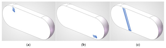
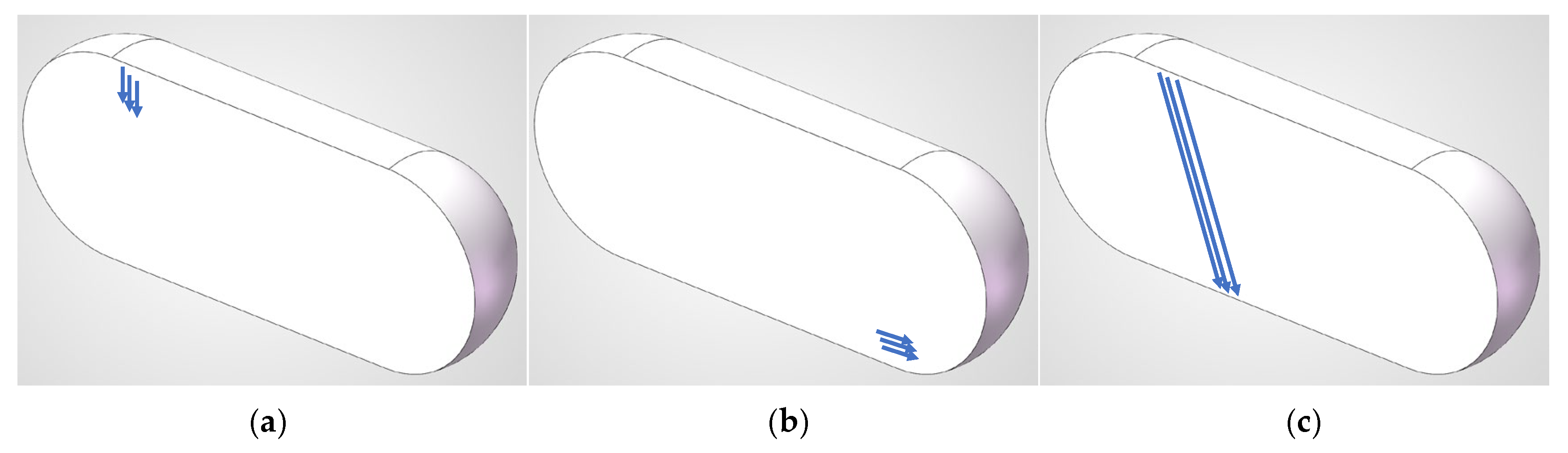
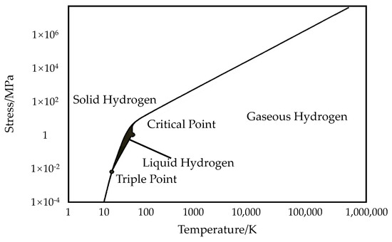
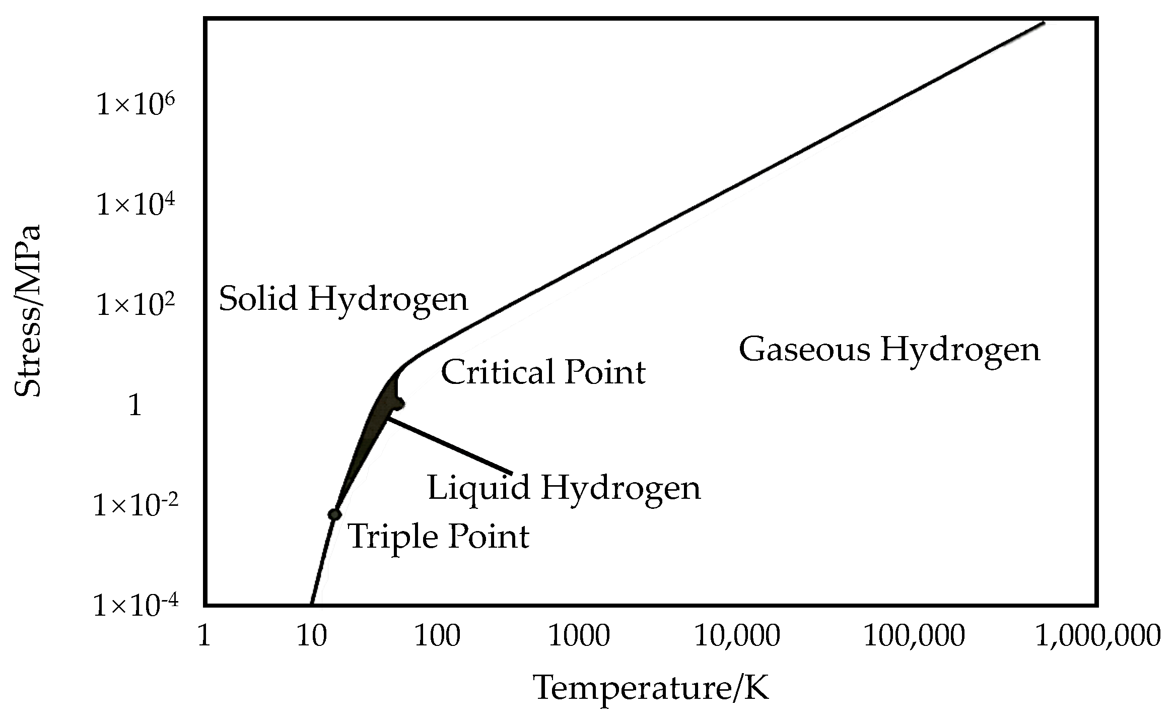
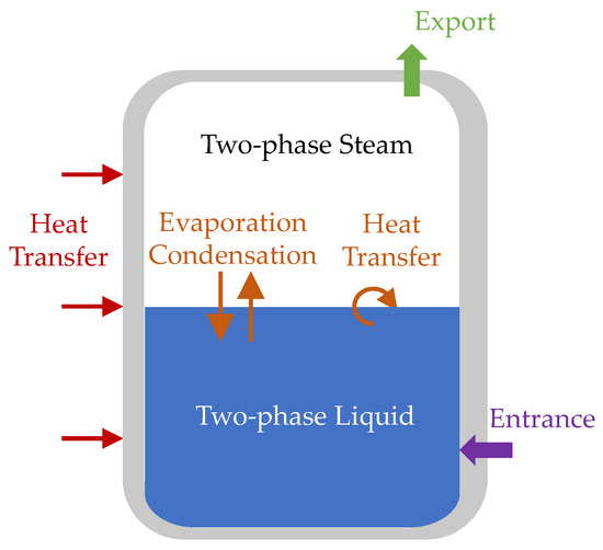
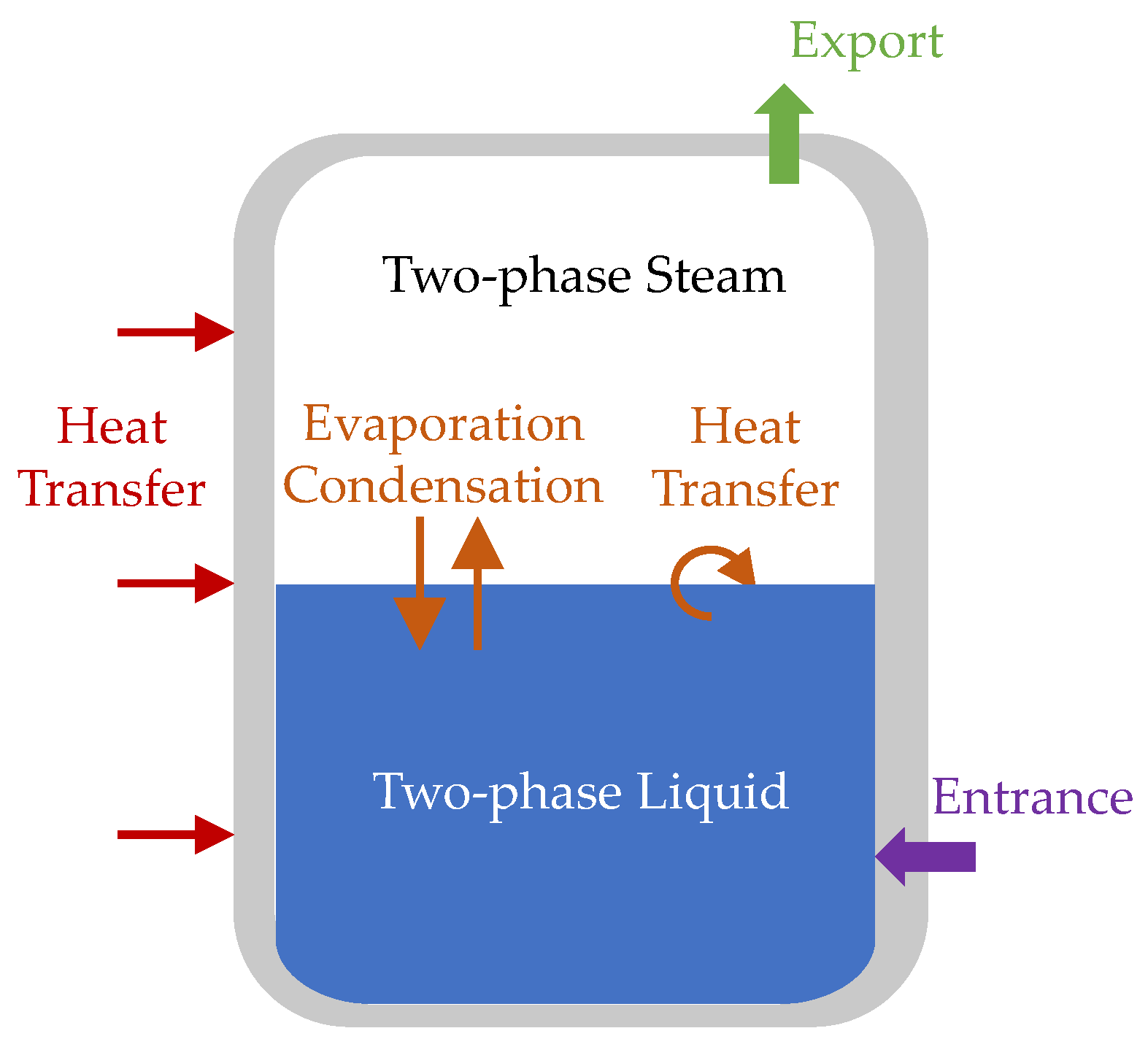
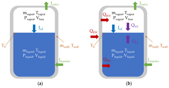
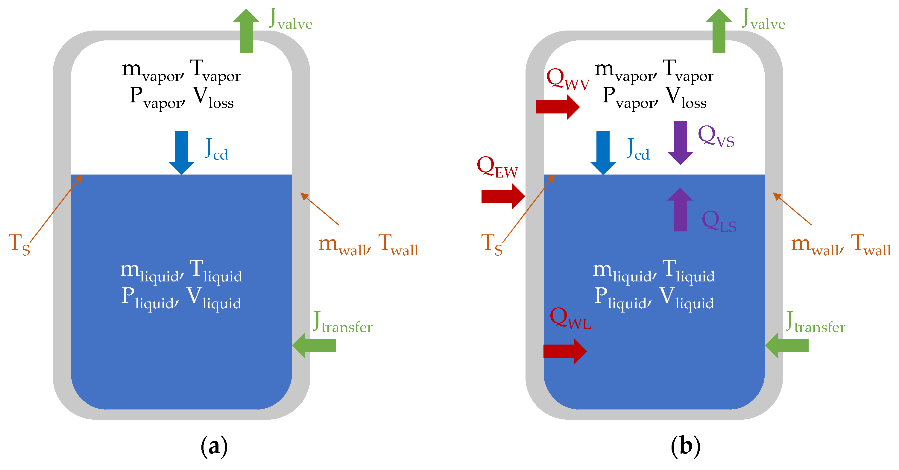
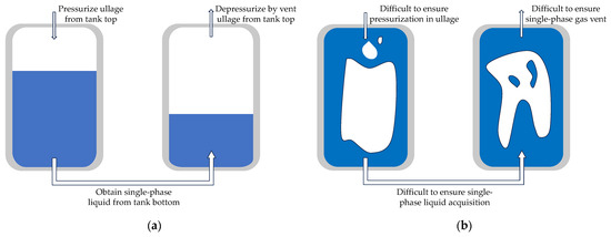
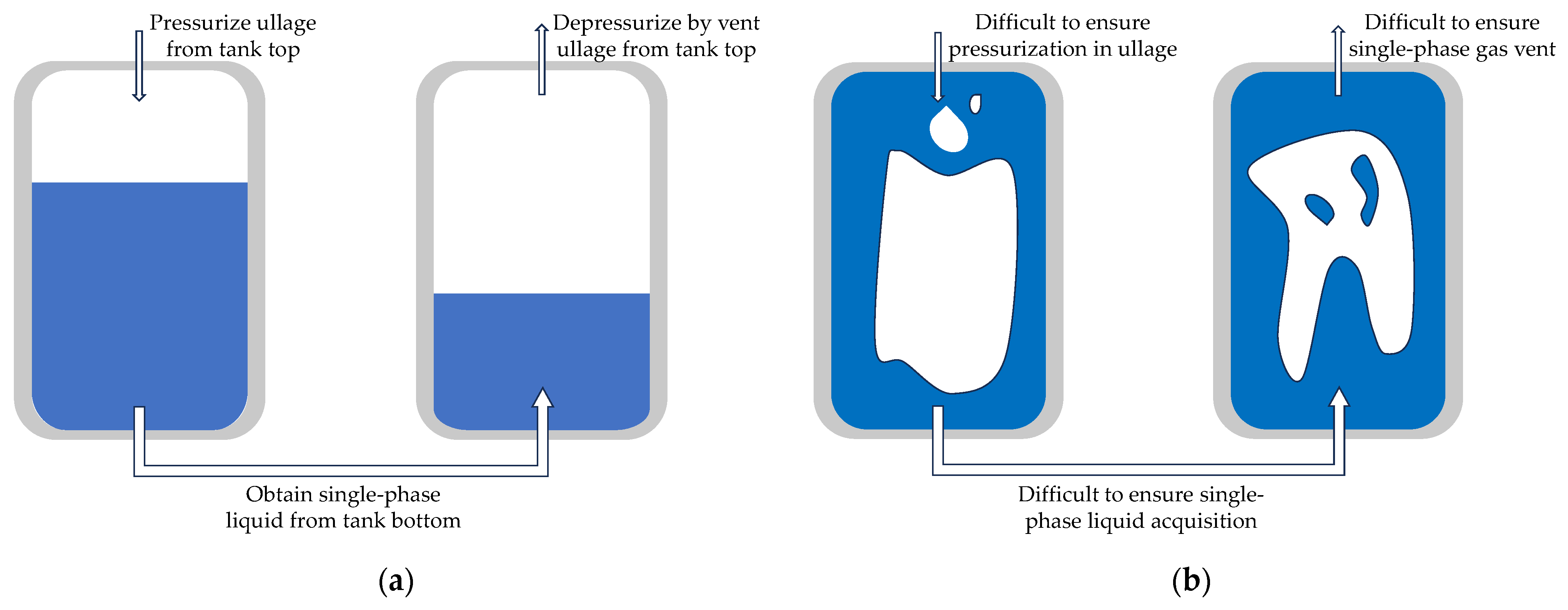
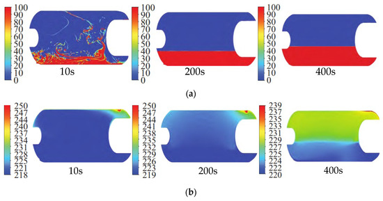
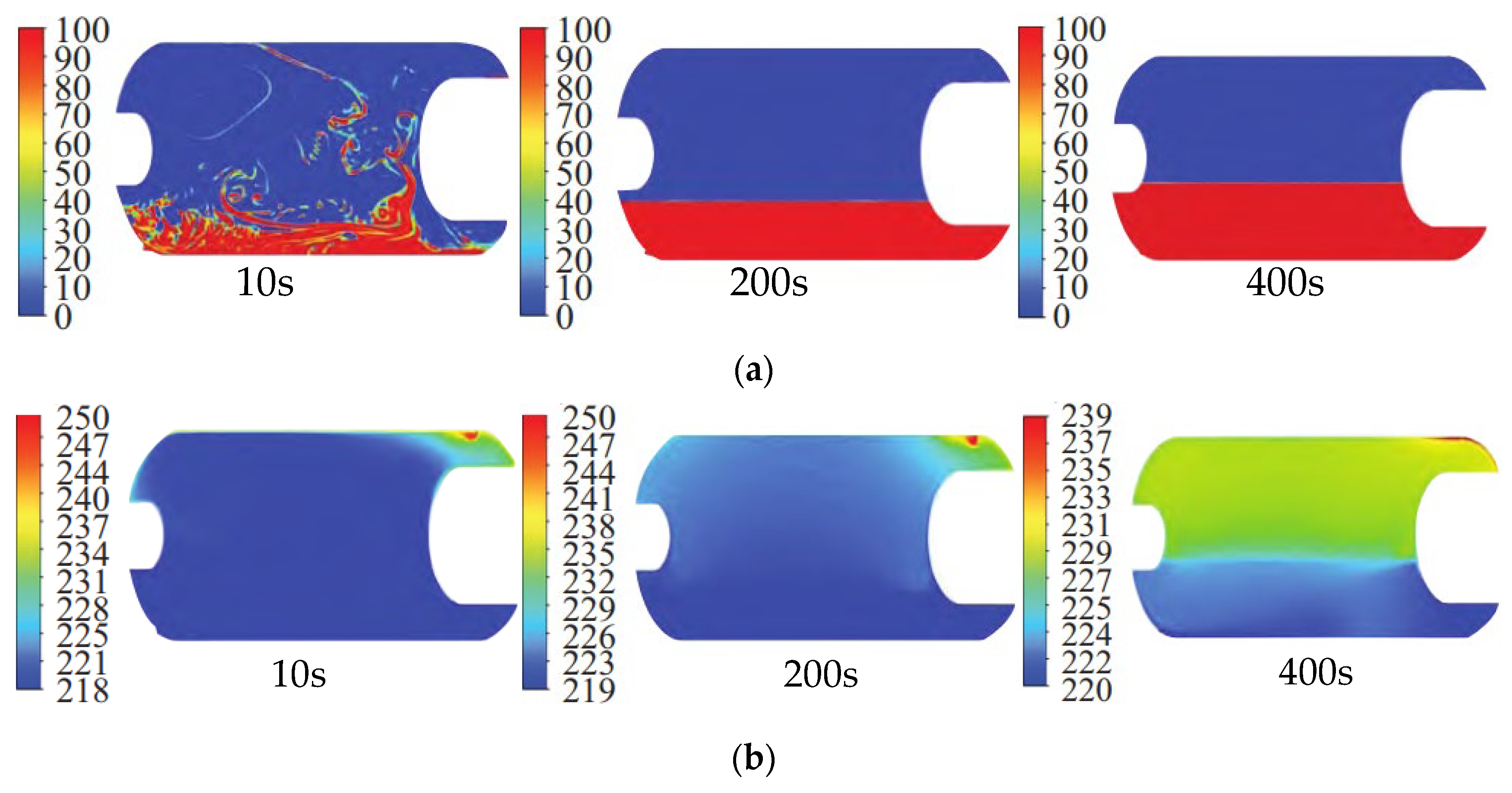
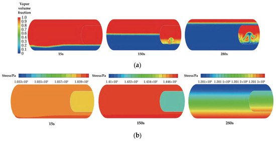
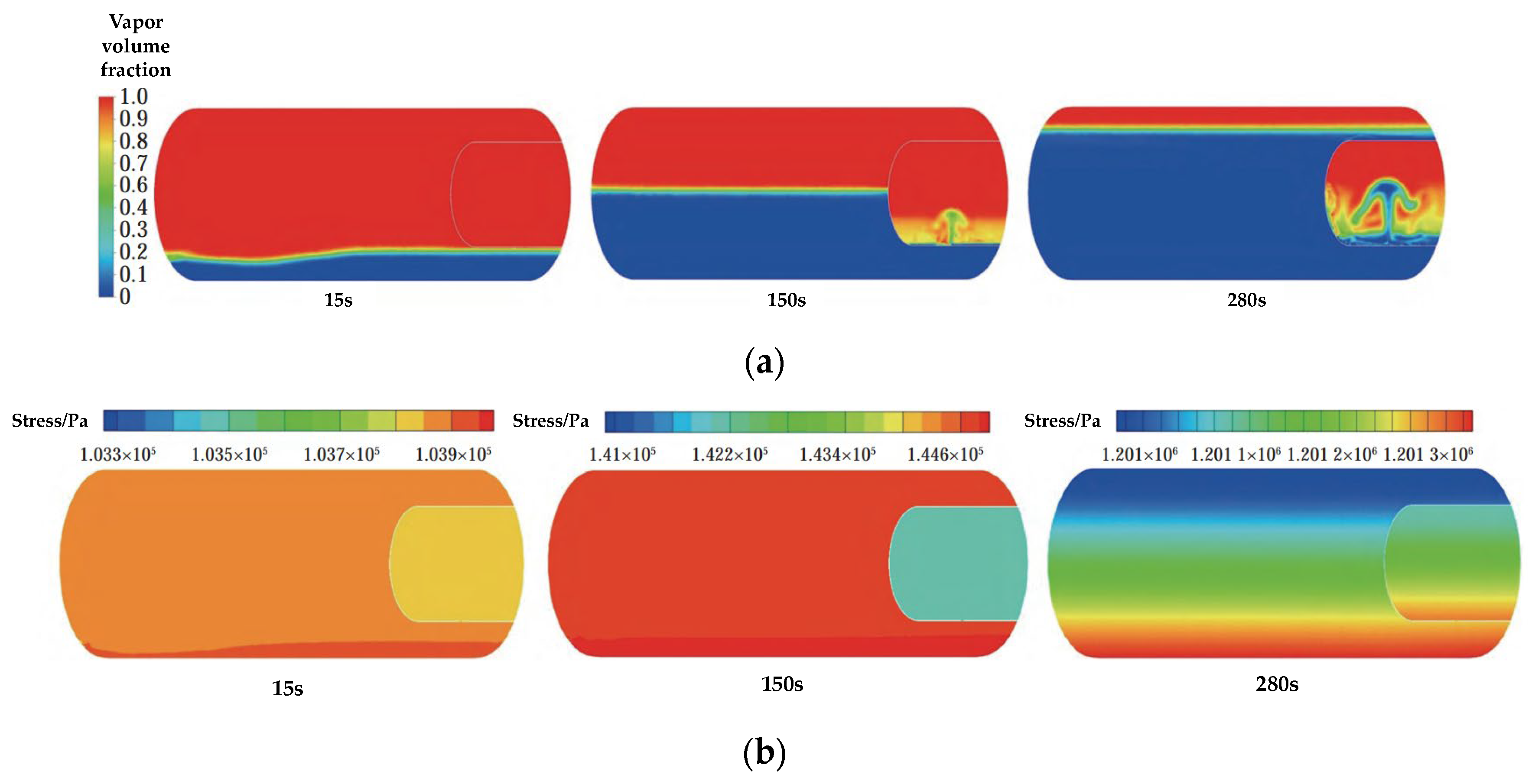
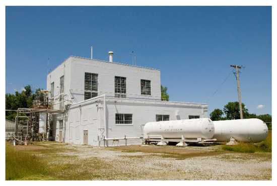
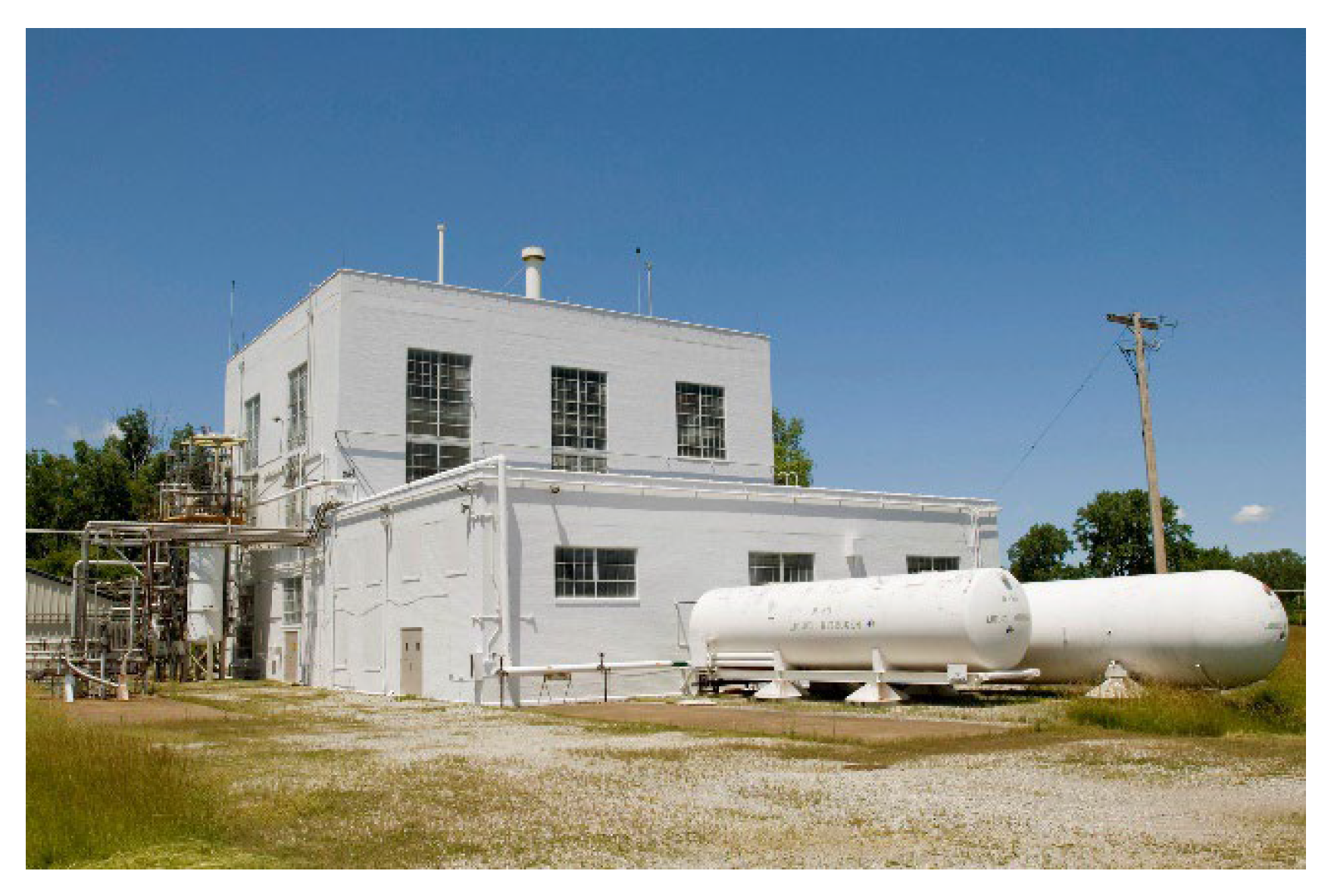
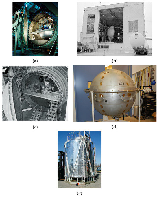
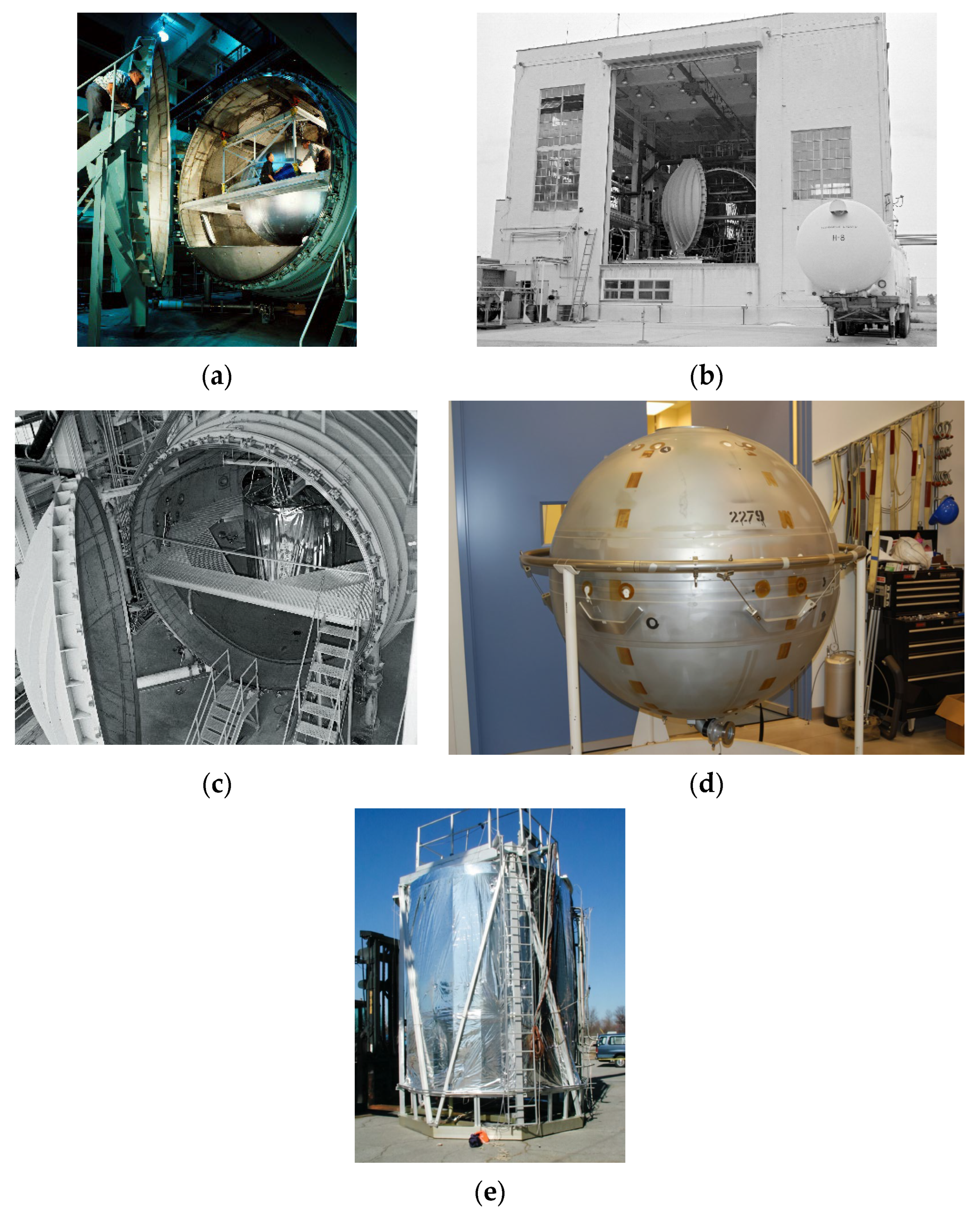
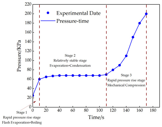
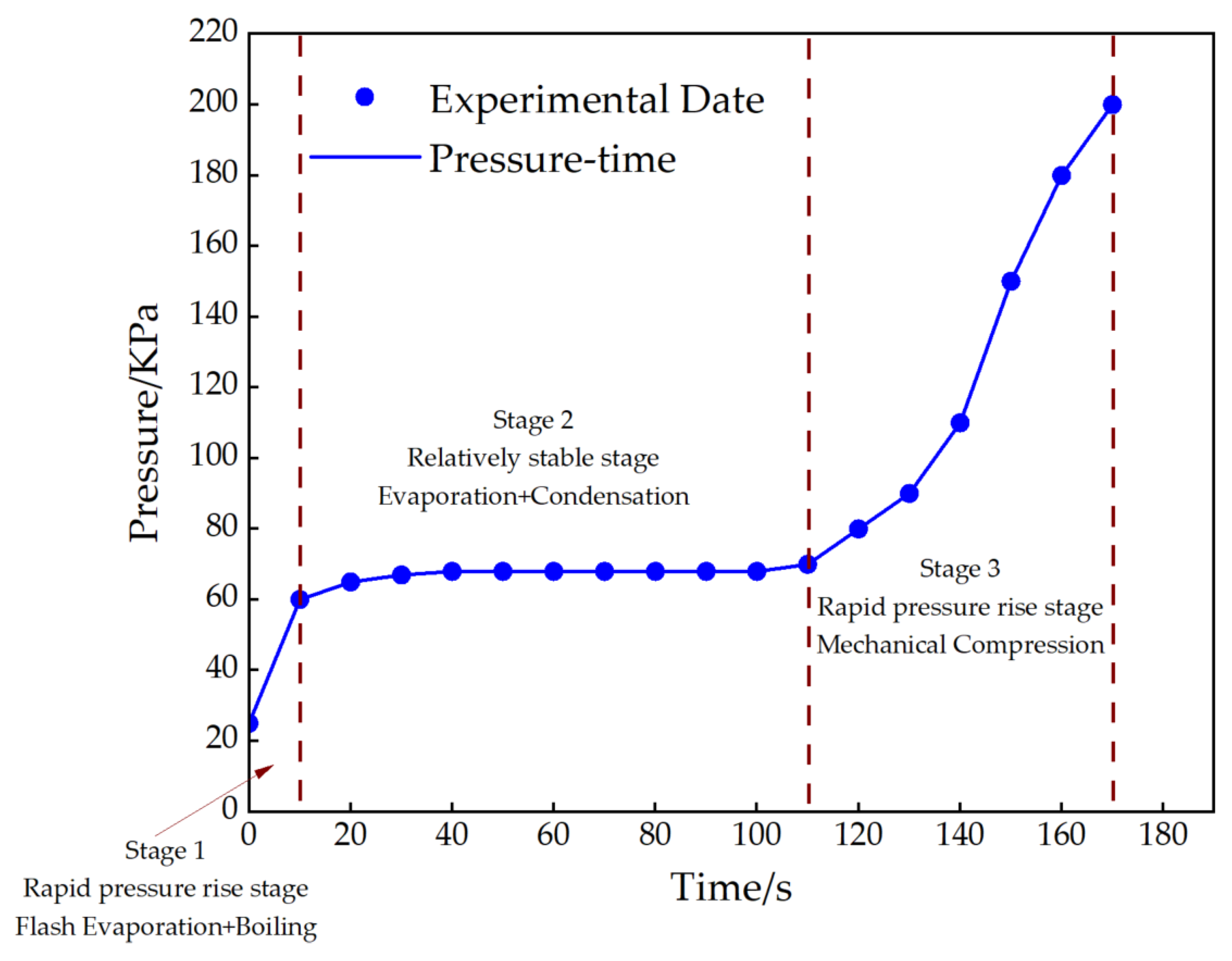
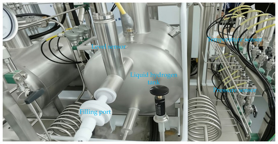
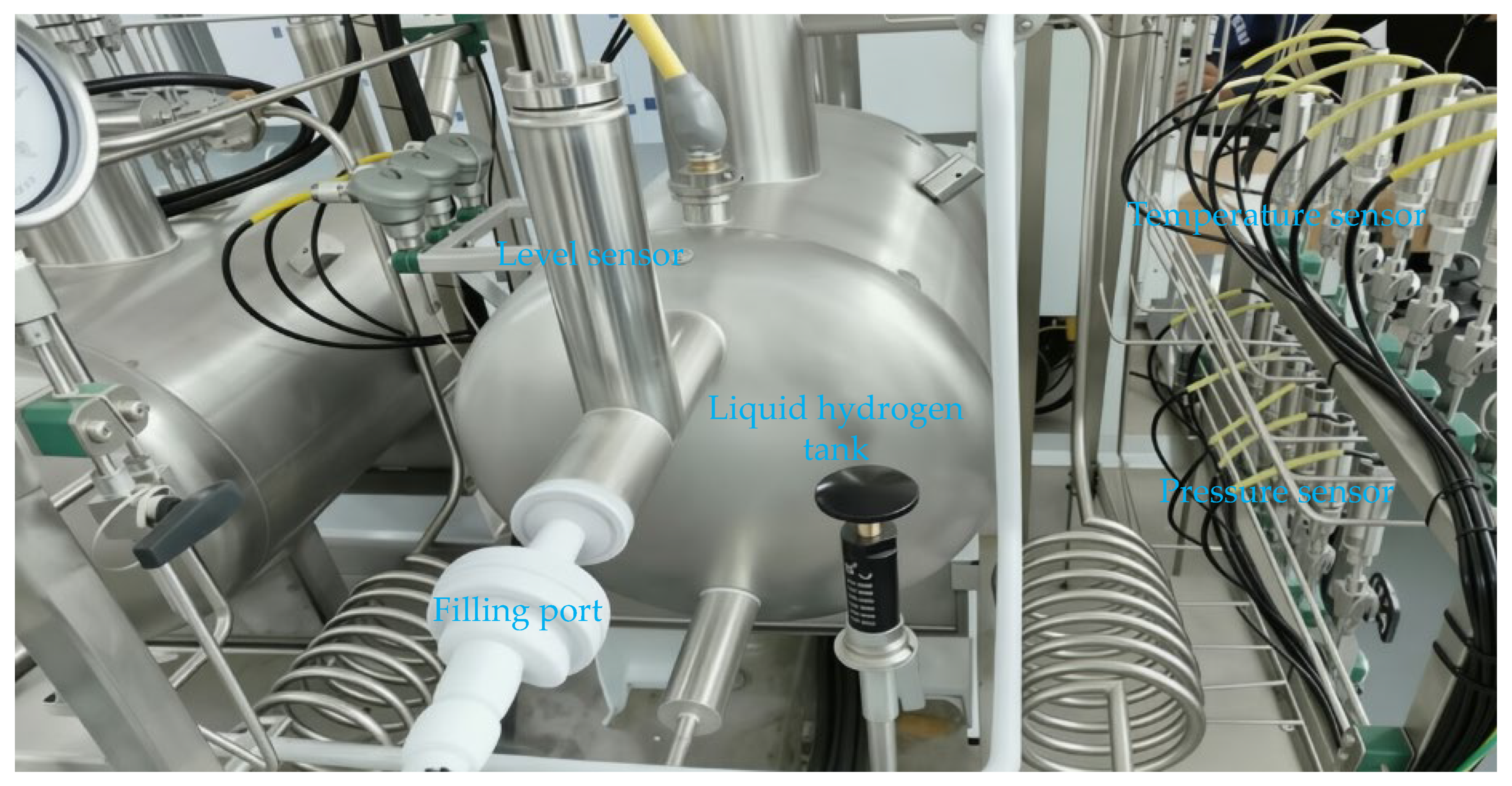
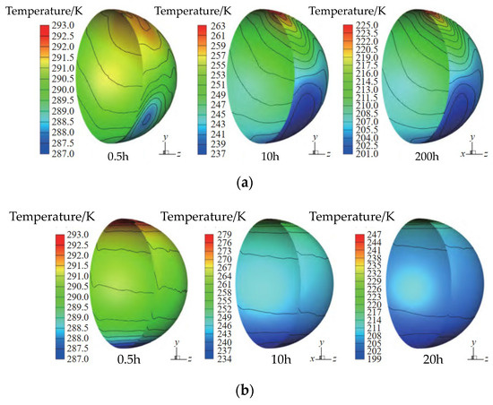
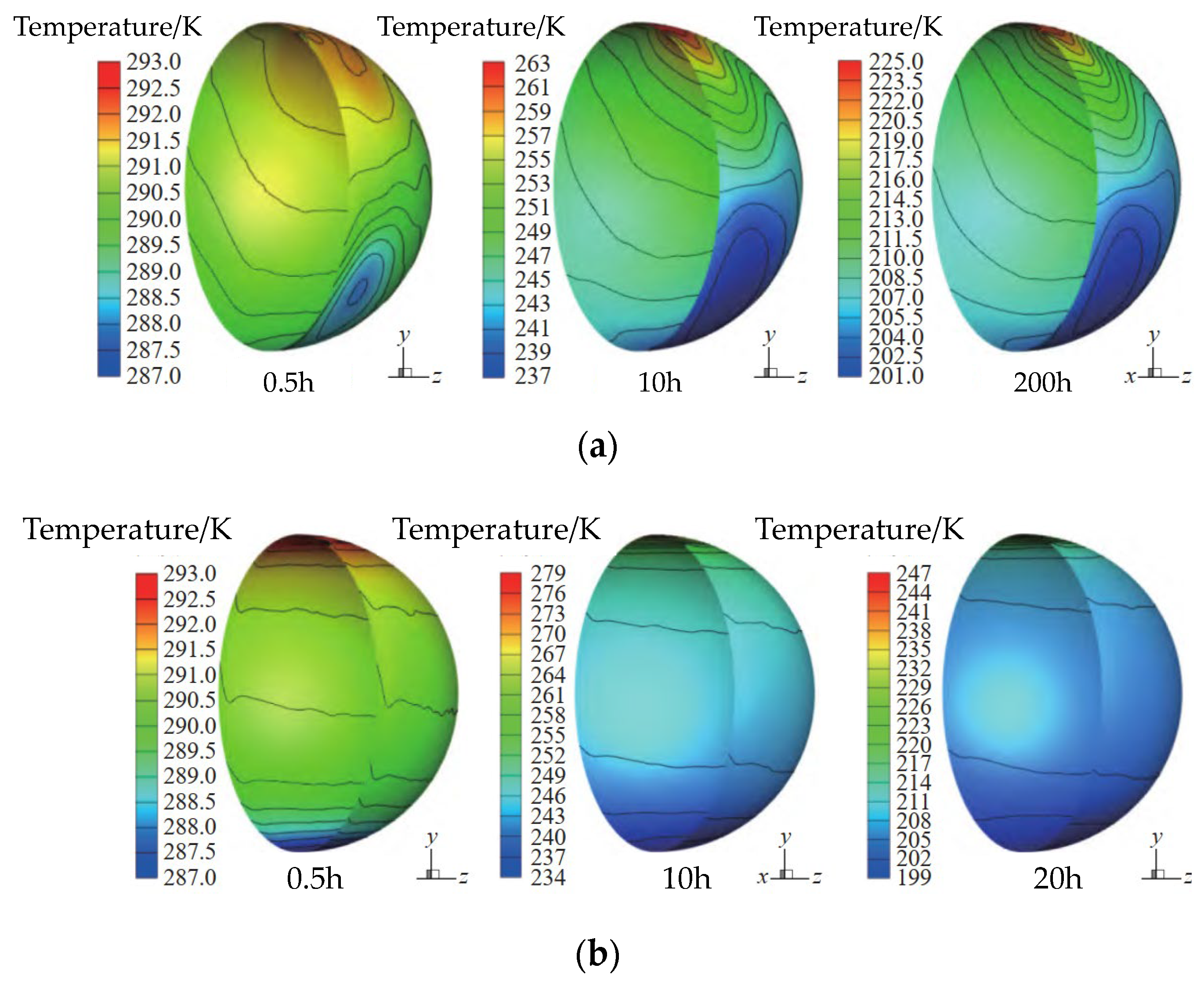

Disclaimer/Publisher’s Note: The statements, opinions and data contained in all publications are solely those of the individual author(s) and contributor(s) and not of MDPI and/or the editor(s). MDPI and/or the editor(s) disclaim responsibility for any injury to people or property resulting from any ideas, methods, instructions or products referred to in the content. |
© 2026 by the authors. Licensee MDPI, Basel, Switzerland. This article is an open access article distributed under the terms and conditions of the Creative Commons Attribution (CC BY) license.