Review

The Integrity and Tightness of Underground Hydrogen Storage Systems: A Critical Review of Geological Barriers, Well Sealing, Leakage Risks and Future Perspectives

1
Laboratory of Applied Geophysics, Geotechnics, Engineering Geology, and Environmental (L3GIE), Mohammadia Engineering School, Mohammed V University, Rabat 10090, Morocco
2
Independent Researcher, Rabat 10090, Morocco
*
Author to whom correspondence should be addressed.
Hydrogen 2026, 7(3), 116; https://doi.org/10.3390/hydrogen7030116
Submission received: 21 June 2026 / Revised: 3 August 2026 / Accepted: 10 August 2026 / Published: 17 August 2026

Abstract

Underground storage of green hydrogen is a strategic enabler of large-scale renewable deployment, but its feasibility rests on a hard problem: keeping a small, highly mobile molecule confined underground for decades without safety or environmental risk. This critical review examines the containment mechanisms of hydrogen across underground storage types, focusing on geological barriers, well integrity and sealing materials. We evaluate the containment capabilities of salt cavities, deep aquifers and depleted reservoirs, with particular attention to the viscoplastic, self-healing properties of salt that promote confinement, and to the vulnerabilities of well infrastructure and salt–cement interfaces. Emerging alternatives, including lined rock caverns and repurposed abandoned mines, are assessed alongside their distinct operating configurations and use cases. Leakage mechanisms including diffusion, advection, microcracking, cement degradation and hydrogen–material interactions are analysed alongside geomechanical modelling, microbial activity, monitoring strategies, regulatory frameworks, and techno-economic and environmental considerations, including the integration of carbon capture, utilisation and storage (CCUS) with underground hydrogen storage. Well integrity emerges as the dominant risk factor across storage types. The review concludes with design criteria, monitoring priorities and research needs to guide the safe, sustainable deployment of underground hydrogen storage, providing a scientific foundation for future numerical and experimental work on storage tightness.

1. Introduction

1.1. Context and Challenges

The move toward low-carbon energy systems has pushed hydrogen to the centre of attention as a clean energy carrier. Green hydrogen, produced from renewable sources via water electrolysis powered by wind and solar energy, is widely seen as a cornerstone of large-scale storage and of decarbonising sectors that resist direct electrification [1,2]. The European Commission’s Hydrogen Strategy, published in 2020, targets 40 GW of electrolyser capacity by 2030 [3], while several national roadmaps in the Middle East, North Africa and Asia-Pacific regions envisage comparable ambitions [4,5]. Because renewable supply is intermittent, it must be paired with storage able to hold large hydrogen volumes for weeks, or even across seasons [6,7].
Underground hydrogen storage (UHS) builds directly on several decades of natural gas storage experience, which makes it one of the more credible options for handling these volumes [8,9]. Nevertheless, the specific properties of hydrogen, including its small molecular size, high diffusivity and interactions with materials, raise major challenges in terms of safety, sealing and integrity of storage systems [10,11]. The hydrogen molecule, with a kinetic diameter of approximately 2.89 Å, is significantly smaller than methane (3.80 Å) or carbon dioxide (3.30 Å), which has profound implications for its containment behaviour in geological formations [12].

1.2. Underground Storage of Hydrogen and the Issue of Sealing

Globally, underground gas storage encompasses 925 facilities with a combined working gas capacity of approximately 4930 × 103 m3 as of 2018, with depleted oil and gas reservoirs accounting for 75.8% of facilities, followed by aquifers (14%) and salt caverns (9.7%) [13].
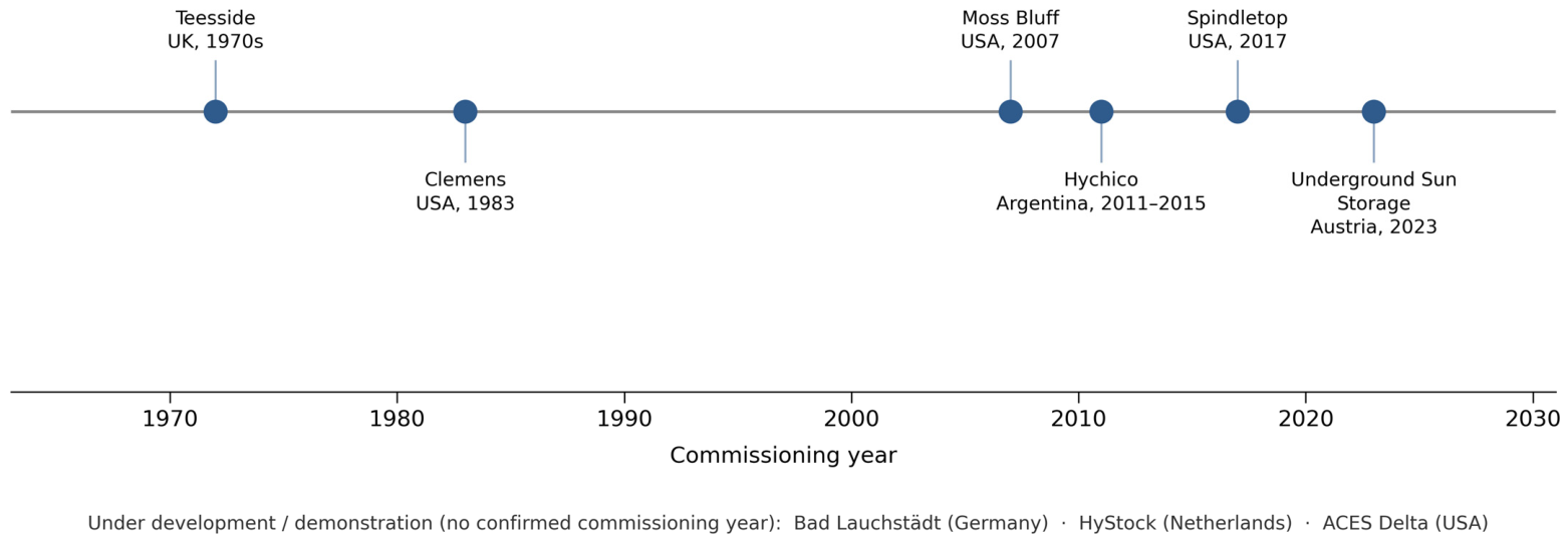
However, despite these advantages, the sealing of storage systems remains a critical issue. Hydrogen can migrate through geological formations, natural discontinuities such as fractures or faults, as well as anthropogenic structures, particularly storage wells [9,11]. Any failure at the level of geological barriers, well integrity or sealing materials can lead to leaks, which may affect the safety of facilities and environmental acceptability of underground hydrogen storage [14,15]. Operational experience with pure hydrogen storage in salt caverns dates to the Teesside facility in the United Kingdom (1970s) and the Texas facilities in the United States (1980s), which provides critical empirical evidence for the feasibility of large-scale UHS [16].

1.3. State of the Art: A Comprehensive Review

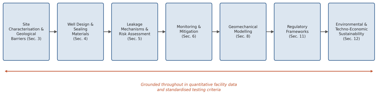
Over roughly five decades, work on UHS integrity has shifted from hands-on industrial operation toward detailed multiphysics analysis. This section provides a structured overview of the existing literature, organised thematically to identify key achievements, methodological approaches, and remaining gaps (Figure 1).

1.3.1. Early Operational Experience and Foundational Studies (1970s–2000s)

The earliest evidence for the viability of large-scale hydrogen storage in salt caverns comes from the Teesside facility in the United Kingdom (operational since the early 1970s) and the Gulf Coast facilities in Texas and Louisiana (commissioned in the 1980s) [16,17,18,19,20,21,22]. These pioneer operations demonstrated that salt formations can safely contain hydrogen over multi-decadal timescales, with no reported major integrity incidents. Foundational geomechanical studies by Carter and Hansen [23], Hunsche and Hampel [24], and Munson and Dawson [25] established the constitutive framework for salt creep behaviour, providing the Norton power law and the Munson–Dawson model that remain widely used today.

1.3.2. Geological and Geomechanical Investigations (2000s–2015)

The second wave of research focused on quantifying the containment properties of different geological formations. Comparative studies evaluated salt caverns, depleted hydrocarbon reservoirs, and deep aquifers as potential hydrogen storage hosts [1,2,6,26,27]. Key contributions in this period included the measurement of hydrogen diffusion coefficients in rock salt (10−12 to 10−14 m2/s) [28,29], capillary entry pressure characterisation of caprocks [30,31], and dilatancy criteria for cavern stability assessment [32,33]. The HyUnder project provided a transferable site-screening methodology, initially applied to Spain, assessing geological, logistical, and economic criteria for viable large-scale hydrogen storage candidates [34]. Coupled thermo-hydro-mechanical (THM) models were developed to capture the interplay between thermal gradients, pore-pressure evolution, and mechanical deformation of host formations [35,36].

1.3.3. Well Integrity and Material Compatibility

A growing body of literature has addressed the vulnerability of wells as preferential leakage pathways [37,38,39]. Historical data from oil and gas operations indicate that approximately 5–10% of wells experience some form of integrity failure during their operational lifetime [38,39]. Research on hydrogen–material interactions has revealed multiple degradation mechanisms: hydrogen-induced cracking (HIC) in carbon and low-alloy steels [40,41], cement microcracking and carbonation under hydrogen-saturated brines [42,43], and explosive decompression of elastomeric seals [44]. Alternative sealing materials, including geopolymer cements, polymer-reinforced formulations, and resin-based sealants, have been explored to enhance long-term hydrogen resistance [45,46].

1.3.4. Thermodynamic, Transport, and Multiphase Flow Studies

Understanding hydrogen behaviour under reservoir conditions has required advances in thermodynamic modelling and experimental characterisation. Modified equations of state incorporating quantum corrections have improved accuracy for hydrogen properties at elevated pressures and temperatures [47]. Experimental determination of hydrogen–brine relative permeabilities [48,49], capillary pressure–saturation relationships [50,51], and viscous fingering phenomena [52,53] have highlighted fundamental differences between hydrogen and conventional gases. The unfavourable mobility ratio between hydrogen and brine (M >> 1) creates unstable displacement fronts that reduce sweep efficiency and require dedicated reservoir management strategies [54,55,56].

1.3.5. Microbial and Geochemical Considerations

An emerging research front addresses the role of subsurface microbial communities in consuming stored hydrogen [57,58,59,60]. Sulphate-reducing bacteria, methanogenic archaea, and acetogenic bacteria can metabolise dissolved hydrogen, producing undesirable by-products (H2S, CH4) and reducing storage efficiency. Field observations from the Lobodice facility in the Czech Republic documented significant hydrogen losses attributed to microbial methanogenesis [60]. Geochemical interactions between hydrogen and reservoir minerals (reduction of iron-bearing minerals, sulphate reduction, carbonate dissolution) can modify the pore structure and mineralogy of host formations [61,62,63,64,65].

1.3.6. Monitoring Technologies and Risk Assessment

Advanced monitoring technologies have been progressively adapted for hydrogen storage applications. Distributed fibre-optic sensing (DTS/DAS) provides continuous real-time monitoring along entire wellbore lengths [66,67]. Satellite-based InSAR offers millimetre-scale surface deformation measurements [68]. Palladium thin-film hydrogen sensors and electrochemical noise analysis enable early detection of hydrogen migration [69,70]. Probabilistic risk assessment frameworks, including Monte Carlo simulations and fault tree analysis, have been adapted from nuclear and petroleum industries to quantify leakage probabilities [71,72].

1.3.7. CCUS–UHS Integration and Techno-Economic Studies

The recent literature has explored the synergies between carbon capture, utilisation and storage (CCUS) and underground hydrogen storage, particularly the use of CO2 as a cushion gas [73,74,75,76]. Techno-economic assessments have evaluated the levelised cost of hydrogen storage in salt caverns at 0.10–0.30 €/kg H2, comparing favourably with above-ground alternatives [77,78,79,80]. Life-cycle assessments have estimated greenhouse gas emissions at 0.2–0.5 kg CO2-eq/kg H2 stored, substantially lower than compressed gas storage above ground [81,82].

1.3.8. Identified Gaps and Limitations

Despite these advances, several critical knowledge gaps persist. Most experimental data on hydrogen–material interactions originate from short-term laboratory tests, and long-term field validation data remain scarce. Hydrogen-specific leakage mechanisms—molecular diffusion, pressure-cycle-induced microcracking, and cement degradation—have not been studied in an integrated, multiphysics framework [10,83]. The interplay between microbial activity, geochemical reactions, and mechanical integrity is poorly understood. Regulatory frameworks remain fragmented across jurisdictions, with hydrogen-specific provisions only beginning to emerge [84,85,86,87,88]. Furthermore, most feasibility studies have focused on European and North American sites; geological assessments of potential UHS sites in the MENA region, Sub-Saharan Africa, and Asia-Pacific remain at early stages. The present review addresses these limitations by providing an integrated critical assessment of all factors governing the integrity and tightness of underground hydrogen storage systems. While recent work has begun to address this gap through extended-duration and cyclic testing—for example, cyclic hydrogen exposure of long-cured well cement over repeated injection–withdrawal cycles [89]—and through synthesis of well-integrity risk factors drawn from multiple field and pilot projects [90], dedicated multi-year field-scale monitoring of steel, cement and elastomer behaviour under real UHS operating conditions, such as those reported for the Underground Sun Storage pilot in Austria [91], remains limited and is identified here as a priority for future research.

1.3.9. Recent Advances (2024–2026)

The period 2024–2026 has brought concrete field validation and new methodological tools that were not available to earlier reviews of this topic. On the demonstration side, the Underground Sun Storage facility in Gampern, Austria, completed two full storage cycles of pure hydrogen in a porous depleted gas reservoir in 2023–2024, confirming 100% hydrogen storage feasibility at reservoir scale; the ACES Delta project in Utah entered active construction targeting large-scale seasonal salt-cavern storage; and Japan enacted its first dedicated hydrogen and CCS legislation in 2024. On the methodological side, coupled thermo-hydro-mechanical damage–healing models for salt caverns were substantially refined, cyclic-loading salt-cavern stability models moved beyond the classical Munson–Dawson framework, non-destructive cyclic testing protocols for well cement under realistic seasonal cycling were published, fibre-optic hydrogen sensors reached parts-per-million detection limits suitable for field deployment, and polymer-sealed dual-cavern configurations were proposed as an alternative to conventional cement-based sealing. These developments are integrated throughout this review (Section 3.6, Section 4.2, Section 6.1, Section 8.1, Section 8.5, Section 10.3, Section 11.4, and Section 14.4) rather than confined to a single subsection, since they bear directly on the geomechanical, material, monitoring, and regulatory dimensions of UHS integrity addressed in each corresponding part of the manuscript.

1.4. Objectives and Originality of the Article

Faced with these limitations, this article proposes an in-depth critical review of the issues related to the sealing of underground hydrogen storage systems. The main objectives are to: (i) analyse the physico-chemical properties of hydrogen influencing its leakage behaviour [10]; (ii) evaluate the role of geological barriers in different storage options, with particular emphasis on salt cavities [6,14]; (iii) examine the integrity of the wells and the performance of sealing materials against hydrogen [37]; (iv) identify the leakage mechanisms and potential migration routes; (v) address the thermodynamic and transport properties of hydrogen in porous media; (vi) review geomechanical modelling approaches for salt-cavern behaviour; (vii) examine the role of microbial activity; (viii) present case studies from existing UHS facilities; (ix) discuss regulatory frameworks; (x) evaluate techno-economic and environmental dimensions; and (xi) explore CCUS-UHS integration perspectives (Figure 2).

2. Physico-Chemical Properties of Hydrogen Influencing Sealing

2.1. Basic Characteristics of Hydrogen

Hydrogen is the smallest and lightest of the known molecules, with a molecular mass of 2 g/mol and a kinetic diameter of approximately 2.89 Å [10,12]. Its small size results in high diffusivity, enabling migration through solid materials, including microcracks and low-permeability porous media [11,83] (Table 1).

2.2. Solubility and Permeability in Materials

Hydrogen exhibits low solubility in water (approximately 1.6 mg/L at 20 °C and atmospheric pressure) and in intact rocks, but its permeability may be significant in degraded or cracked materials, such as old well cements or lithological intercalations in salt [14,45]. Experimental measurements by Hassanpouryouzband et al. [51] demonstrated that hydrogen solubility in formation brines decreases with increasing salinity, a factor that is particularly relevant for salt-cavern storage environments. In addition, chemical interactions with certain metals and cements can cause embrittlement or cracking effects, contributing to preferential pathways of escape [37,92]. The phenomenon of hydrogen-induced cracking (HIC) in carbon and low-alloy steels is well documented in the petroleum industry and has direct implications for well casing integrity in UHS applications [40].

2.3. Diffusion and Molecular Migration

The diffusion behaviour of hydrogen depends on the temperature, pressure, and porosity of the material being passed through. Experimental and numerical studies have shown that, even in supposedly watertight formations, microcracks or cementing defects can allow hydrogen to migrate over significant distances, particularly over prolonged periods [10,83]. The effective diffusion coefficient in rock salt has been estimated to range from 10−12 to 10−14 m2/s, depending on the crystallographic orientation and the presence of fluid inclusions [28,29]. Diffusion is particularly critical during repeated cycles of injection and withdrawal, which induce pressure variations that can widen the existing cracks. Knudsen diffusion may become dominant in nanoporous materials where pore diameters approach the mean free path of hydrogen molecules [93].

2.4. Interactions with Sealing Materials and Wells

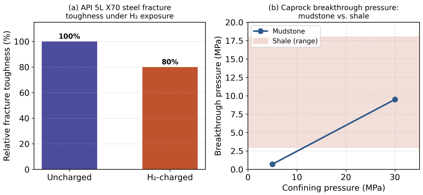
Cements and other sealants used in wells are exposed to long-term hydrogen, which can cause cement microcracking, corrosion of metal tubing, or formation of preferential migration pathways at the cement–rock interface [11,37]. Hydrogen embrittlement of steel is a well-known phenomenon in which atomic hydrogen diffuses into the metal lattice, accumulates at grain boundaries and inclusions, and causes a loss of ductility and eventual cracking [40,41]. For steel casings and tubing, austenitic stainless steel grades with nickel content exceeding 12% are recommended to resist hydrogen embrittlement, with yield strength kept below 80 MPa to limit stress-corrosion susceptibility [13]. Elastomeric components, including packers and seals, require hydrogenated nitrile rubber (HNBR) rather than standard NBR [44]. These phenomena are aggravated by temperature and pressure variations, highlighting the importance of selecting resistant materials and implementing continuous monitoring. To quantify this effect, hydrogen-charged API 5L X70 pipeline steel base metal showed a 20% reduction in fracture toughness relative to uncharged specimens [94], while cyclic hydrogen exposure of well cement (10.34 MPa, 50 °C, three 28-day cycles) produced measurable increases in porosity and permeability, although ultrasonic velocity remained largely unaffected, indicating that bulk mechanical integrity is retained even as pore-scale transport properties degrade [89].

2.5. Implications for Waterproofing

The physico-chemical properties of hydrogen explain why salt cavities are often preferred: salt has a low intrinsic permeability (typically less than 10−21 m2) and a viscoplastic behaviour that promotes self-healing of microcracks [6,45,95]. Nevertheless, even under these ideal conditions, successful containment strongly depends on the quality of well sealing, the absence of permeable intercalations in the surrounding rock, and continuous monitoring to detect any abnormal hydrogen migration (Table 1). Thus, understanding the physical and chemical characteristics of hydrogen is essential for designing safe and sustainable storage systems.

3. Geological Barriers and Containment Mechanisms

3.1. Types of Geological Formations for Hydrogen Storage

Underground storage of hydrogen can be carried out in several types of geological formations: saline cavities, depleted hydrocarbon reservoirs and deep aquifers [2,6,26]. Each of these options has specific advantages and constraints in terms of sealing. Saline cavities are characterised by a low permeability, a viscoplastic behaviour of the salt and a self-healing of microcracks, which positions them as the safest solution for hydrogen containment [6,45]. Depleted reservoirs offer existing porosity and infrastructure already in place, but present a potential presence of fractures and permeable intercalations that can create leakage pathways [1,9]. Deep aquifers have a large theoretical capacity, but are confronted with geological heterogeneity and the complexity of hydrogen–water interactions that can affect sealing [2,10]. Lined rock caverns (LRCs) represent an additional option, in which an excavated cavern is lined with a steel membrane and concrete backfill to provide a gas-tight barrier independent of the host-rock permeability [96,97].

3.2. Caprocks and Integrity of Natural Barriers

The effectiveness of geological formations mainly depends on the integrity of the upper barrier (caprock). The caprocks must have a low intrinsic permeability, sufficient geological continuity to prevent vertical migration, and mechanical strength suitable for pressure variations during injection and withdrawal cycles [6,10,14]. Typical caprock formations include evaporites (anhydrite, halite), dense shales, and tight carbonates, with permeabilities ranging from 10−18 to 10−22 m2 [98]. Capillary entry pressure is a critical parameter; the two-phase flow threshold at which hydrogen can displace water from pore throats determines the maximum operating pressure of the storage system [30,31]. Studies show that even weak fractures or areas of low density can constitute preferential migration paths for hydrogen, particularly in depleted aquifers and reservoirs [10,83]. Quantitatively, mudstone breakthrough pressure has been shown to rise from approximately 0.7 MPa to 9.5 MPa as confining pressure increases from 5 to 30 MPa, while shale entry pressures span from a few MPa up to nearly 18 MPa depending on lithology and burial history, underscoring that caprock sealing capacity cannot be treated as a fixed threshold but must be assessed under site-specific stress conditions [30] (Figure 3).

3.3. Interactions Between Cavities and the Surrounding Rock

In the case of salt cavities, salt exhibits viscoplastic behaviour that allows the cavity wall to deform slowly and naturally fill cracks [6,45]. This self-healing mechanism limits long-term hydrogen losses and is a major advantage over other types of formation. The constitutive behaviour of rock salt is commonly described by steady-state and transient creep models, with the Norton power law being widely applied: ε̇ = A·σn·exp(−Q/RT), where A is a material constant, n is the stress exponent (typically 3–5 for rock salt), Q is the activation energy, R is the gas constant, and T is the absolute temperature [23,24]. However, lithological intercalations (clay, limestone, sandstone) within the salt may form more permeable zones, increasing the risk of leakage if not properly considered in site design and assessment [14,45].

3.4. Evaluation of the Performance of Geological Barriers

The assessment of geological integrity involves several approaches. In situ characterisation includes permeability measurements, pressure tests and strain monitoring [6,45]. Nitrogen or brine leak tests are standardised methods for verifying cavern tightness before commissioning hydrogen operations [99]. Numerical modelling is based on multiphysics simulations to predict the long-term behaviour and potential migration of hydrogen [14,83]. Coupled thermo-hydro-mechanical (THM) models have been developed to capture the interplay between thermal gradients, pore-pressure evolution, and mechanical deformation of the host formation [35,36]. Historical analysis and analogies use natural gas storage data to estimate formation performance and identify leakage risks [8,9]. These methods make it possible to identify risk areas and plan appropriate monitoring strategies.

3.5. Summary

Geological barriers constitute the first rampart against hydrogen leakage (Table 2). Among them, salt cavities present the best compromise between security, sealing and storage capacity [6,45]. However, even under these conditions, successful containment depends on careful site selection, integrity of the caprocks and surrounding rock, consideration of permeable intercalations, and continued monitoring of storage.

3.6. Emerging Alternative Sites: Abandoned Mines and Lined Rock Caverns

Beyond salt cavities, depleted reservoirs, aquifers and purpose-built lined rock caverns (LRCs), repurposed abandoned mines and mining tunnels are increasingly discussed as additional storage sites, particularly in regions with a legacy of coal or metal mining and limited access to salt formations. The engineering precedent for these concepts comes largely from compressed-air energy storage (CAES), which shares the same airtightness and cyclic-loading challenges as UHS. Kim et al. [100] modelled the air tightness and energy balance of CAES in lined rock caverns at shallow depth, demonstrating that a steel or composite liner can decouple gas-tightness from host-rock permeability, in the same way LRCs are proposed for UHS. Álvarez de Prado et al. [101] compared fibre-reinforced polymer (FRP) and steel sealing layers for CAES reservoirs in abandoned mine tunnels, finding that liner material choice materially affects thermodynamic performance and cyclic durability; Schmidt et al. [102] subsequently assessed the technical feasibility of lined mining tunnels in closed coal mines as CAES reservoirs, addressing rock-mass characterisation, liner design and long-term structural stability under repeated pressure cycling. These concepts have not yet been demonstrated for hydrogen specifically, and the smaller molecular size and higher diffusivity of hydrogen relative to air will likely place more stringent demands on liner material selection and joint sealing than in the CAES precedents. Configurations and use cases also differ systematically across site types: salt cavities and LRCs support high-frequency, high-deliverability cycling (daily to weekly) suited to grid balancing and ancillary services; depleted reservoirs and aquifers offer the largest capacities but lower cycling frequency, suited to seasonal or strategic buffer storage; and repurposed abandoned mines, where feasible, are positioned as a distributed, regionally accessible option for medium-scale, medium-frequency storage in areas lacking salt or suitable porous formations. This distinction in configuration and intended use should inform site-selection and sealing-material decisions alongside the purely geological and geomechanical criteria discussed above.A comparative summary of the containment characteristics of these storage options is given in Table 3.

4. Integrity of Wells and Sealing Materials

4.1. Role of Wells in Underground Storage

Leaks can occur at the cement–rock interface, within metal tubing, or in defect areas in the cement as a result of repeated pressure cycles [37,83]. Historical data from oil and gas operations indicate that approximately 5–10% of wells experience some form of integrity failure during their operational lifetime [38,39]. The safety and tightness of storage therefore strongly depend on the quality of the materials used and the construction and maintenance procedures.

4.2. Sealing Materials

Sealing materials, mainly Portland-based cement, must withstand hydrogen diffusion, pressure and temperature variations, and chemical interactions with hydrogen [11,37]. Recent research shows that hydrogen can cause cement microcracking or preferential channel formation, reducing its long-term effectiveness [37]. The carbonation and leaching of cement in the presence of hydrogen-saturated brines can increase porosity and permeability by up to two orders of magnitude over decadal timescales [42,43]. Alternative or improved materials, such as low-permeability cements, geopolymer cements, polymer-reinforced formulations, or resin-based sealants, are explored to minimise these risks [45,46]. Cement formulations should minimise silica content to reduce pozzolanic reactions in the presence of hydrogen [13]. Beyond well cements, engineered polymer and composite liners are being explored as an alternative or complementary sealing strategy for cavernscale UHS: Hu et al. [103] developed a fully coupled thermo-mechanical model of a polymer-sealed dual-cavern hydrogen storage system in heterogeneous rock, showing that the polymer sealing layer must be co-designed with the surrounding rock-mass heterogeneity (represented via a Weibull strength distribution) and fracture network to withstand cyclic thermo-mechanical loading. Compacted bentonite, widely used as an engineered sealing/buffer material in nuclear waste repository tunnels, offers a further analogue: Rutqvist et al. [104] modelled the coupled thermo-hydro-mechanical-chemical response of bentonite-backfilled repository tunnels, a sealing concept whose self-swelling, low-permeability behaviour is conceptually relevant to shaft- and tunnel-sealing applications in repurposed mine and lined-cavern UHS sites (Section 3.6), though its compatibility with hydrogen specifically has not yet been tested. Sealing-material selection should therefore be treated as configuration-specific: Portland-based and geopolymer cements for well completions, and polymer, composite or bentonite-based liners for cavern and tunnel-scale barriers, each requiring separate qualification against hydrogen exposure.

4.3. Factors Influencing Well Integrity

Several factors can compromise the sealing of wells. Repeated pressure cycles, generated by hydrogen injection and extraction, cause pressure variations that can widen microcracks in the cement [10,37]. Chemical compatibility is also a problem because hydrogen interacts with certain metals and cements, which can lead to corrosion or embrittlement [11,37]. Construction defects, such as improperly cemented wells or misaligned tubing, are potential escape routes [8,9]. Material ageing, a natural process affecting cement and tubing, can reduce waterproofing over the years [37,45]. An additional degradation mechanism is microbial activity: sulphate-reducing bacteria (SRB) and methanogenic archaea thrive in the subsurface environment and catalyse reactions that consume stored hydrogen (see Equations (1) and (2) in Section 9.2), with direct consequences for both storage capacity and extracted gas purity [16,57].

4.4. Monitoring and Maintenance

To ensure well integrity, active monitoring strategies are required. Leak detection is carried out using pressure and gas sensors in and around the wells [37]. Distributed fibre-optic sensing (DFOS) technologies, including distributed temperature sensing (DTS) and distributed acoustic sensing (DAS), offer continuous real-time monitoring along the entire wellbore length [66,67]. Regular inspection of tubing and cement involves physical measurements and chemical analyses to detect corrosion or microcracking [45]. Preventive maintenance includes repairing or replacing degraded sections to limit the risk of leakage [37]. Cement bond logs (CBL) and ultrasonic imaging tools provide quantitative assessments of cement quality behind casing [105].

4.5. Summary

Well integrity and the performance of sealing materials are decisive for UHS tightness: even with the natural barrier that salt caverns provide, a single failing well can undermine the whole system [6,37,45]. The choice of materials, the control of their compatibility with hydrogen and a continuous monitoring strategy are therefore key elements to ensure safe and sustainable storage.
Table 3. Comparison of underground hydrogen storage options in terms of tightness and maturity.
Storage TypeTightnessTechnology MaturityTypical Operating PressureTypical Operating Temperature
Salt cavernsExcellentHigh~60–200 bar (depth-dependent)~20–50 °C
AquifersModerateLow~80–200 bar (depth-dependent)~30–70 °C
Depleted reservoirsModerateModerate~50–250 bar (bounded by historical reservoir pressure)~30–90 °C
Lined rock cavernsHigh (if liner intact)Demonstration~100–300 bar (engineered, liner-dependent)~10–30 °C (near-surface)

5. Hydrogen Leakage Mechanisms and Migration Routes

5.1. Hydrogen Leakage Mechanisms

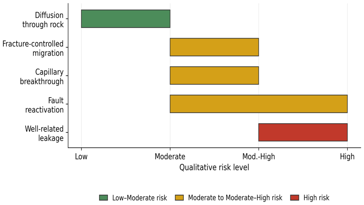
Hydrogen leaks in underground storage systems can result from several mechanisms, acting alone or in combination. Due to its small molecular size and high diffusivity, hydrogen is particularly likely to migrate through supposedly airtight environments [10,11]. The principal leakage mechanisms identified in the literature are: (i) molecular diffusion through porous or microcracked materials [10,83]; (ii) advection related to pressure gradients between the cavity and the surrounding formation [1,9]; (iii) mechanically induced microcracking from repeated cycles of injection and withdrawal [37,45]; (iv) degradation of well materials, in particular cements and casings [11,37]; and (v) two-phase flow through capillary breakthrough when the gas-phase pressure exceeds the capillary entry pressure of the pore network [30,31] (Figure 4).

5.2. Potential Migration Routes

5.2.1. Geological Routes

Geological pathways include pre-existing natural fractures and faults in the reservoir rock or caprock [10,83]; permeable lithological intercalations, notably in heterogeneous salt formations [14,45]; as well as areas of thin caprock thickness, promoting vertical migration [2,6]. Even when the average permeability of the formation is low, the presence of local discontinuities can be sufficient to allow gradual hydrogen migration over the long term [10]. Fault reactivation under elevated pore pressures represents an additional risk that must be assessed through geomechanical analysis [106,107].

5.2.2. Anthropogenic Pathways

Anthropogenic pathways are mainly associated with existing or abandoned wells, which often constitute the preferred escape routes [8,9,37]. The main sources of failure include poorly cemented or partially cemented wells, defects at the cement–rock interface, corrosion of metal tubing, as well as the presence of undocumented old wells [37] (Table 4). In many cases, studies show that the observed leaks are more related to well failures than to a loss of integrity of the geological formations themselves [8,9,38]. In regions with extensive petroleum exploration histories, the density of legacy wells may exceed 10 per km2, creating a complex network of potential leakage pathways that must be mapped and assessed [108].

5.3. Influence of Operating Conditions

Operating conditions play a determining role in the development of leakage mechanisms. Pressure cycles induced by repeated injection and withdrawal of hydrogen can cause mechanical fatigue of materials, widen existing microcracks and modify stresses around wells and cavities [10,45]. The frequency and amplitude of these cycles are particularly important; high-frequency cycling, as might occur in daily load-following applications, imposes greater mechanical demands than seasonal storage operations [109]. Furthermore, excessive pressures can exceed the caprock resistance thresholds, significantly increasing the risk of hydrogen migration [6,83]. Thermal effects associated with the Joule–Thomson cooling during gas expansion and the heat of compression during injection introduce additional thermo-mechanical stresses on well materials and near-wellbore formations [110].

5.4. Risk of Leakage Assessment

The evaluation of leak risks is based on a combination of geological and geomechanical data, well-integrity analyses, as well as multiphysical numerical modelling to anticipate long-term behaviours [14,83]. Probabilistic risk assessment (PRA) frameworks, including Monte Carlo simulations and fault tree analysis, have been adapted from nuclear and petroleum industries to quantify leakage probabilities and consequences [71,72]. Recent studies indicate that, in the case of properly designed and operated salt caverns, hydrogen losses generally remain very low (<1% over several decades), provided well integrity is ensured [14,45].

5.5. Summary

The mechanisms of hydrogen leakage are closely linked to the intrinsic properties of hydrogen, the geological characteristics of the site and the quality of well structures. If the saline cavities offer a high level of safety thanks to their low permeability and self-healing capacity, the wells remain the critical link in the containment system [6,37,45]. A thorough understanding of the mechanisms of leakage is therefore essential to ensure the safety and sustainability of underground hydrogen storage.

5.6. Relative Importance and Ranking of Leakage Pathways by Storage Type

The leakage mechanisms described above do not carry equal weight across storage settings, and this differentiation is central to risk-based prioritisation. In salt caverns, the rock matrix itself provides an effective barrier: molecular diffusion and capillary breakthrough through intact salt are negligible over operational timescales given salt’s very low permeability and self-healing capacity [6,45]; well integrity is therefore the dominant risk factor, consistent with field evidence that observed leaks are more often attributable to well failures than to loss of geological containment [8,9,38]. In depleted hydrocarbon reservoirs and saline aquifers, by contrast, the porous rock matrix and caprock are active elements of the containment system rather than passive hosts: caprock heterogeneity, including undetected fracture networks and lithological discontinuities, becomes a first-order risk factor alongside well integrity, and the higher density of legacy wells in mature hydrocarbon basins (locally exceeding 10 wells per km2 [108]) compounds this risk through undocumented or poorly abandoned penetrations. Molecular diffusion and mechanically induced microcracking remain secondary contributors to overall leakage risk in both settings relative to well- and caprock-related pathways, though they gain relative importance over multi-decadal storage horizons and under high-frequency cycling. This ranking—well integrity as the dominant factor in salt caverns, and the combination of well integrity and caprock heterogeneity in porous formations—is used to guide the prioritisation of monitoring and mitigation strategies discussed in Section 6, and the geomechanical and risk assessment discussions in the sections that follow.

6. Monitoring and Mitigation Strategies

6.1. Monitoring of Watertightness

Monitoring is a key element to ensure the integrity and tightness of underground hydrogen storage systems in the long term. It aims to detect early any anomaly that may indicate hydrogen migration or leakage [37]. The main monitoring techniques include continuous measurement of pressures in the cavity and surrounding formations [6,83]; gas detection near wells and at the surface [37]; geomechanical tracking, including the measurement of deformations and convergence of salt cavities [45]; as well as geophysical methods (seismic, acoustic) to identify the evolution of geological discontinuities [10]. Time-lapse seismic surveys and microseismic monitoring can detect changes in the gas–water contact and identify the reactivation of faults or fractures [111,112]. Satellite-based interferometric synthetic aperture radar (InSAR) provides millimetre-scale surface deformation measurements that can indicate subsurface pressure changes or volume variations in storage caverns [68] (Table 5). Beyond simply listing these techniques, their practical value depends on detection sensitivity and field validation status, which vary considerably: pressure monitoring and cement bond logging are mature, industry-standard tools, whereas InSAR and microseismic monitoring have been validated primarily in CO2 storage monitoring, verification and accounting (MMV) programmes and have not yet been demonstrated at an operating UHS site; distributed fibre-optic sensing is field-proven for oil and gas leak detection but its H2-specific signature interpretation remains largely unvalidated; and point gas sensors have achieved ppm-level detection limits in the laboratory (e.g., 3 ppm for a fibre-optic WO3-PdPt-Pt sensor [113]) but have seen limited field deployment specifically for hydrogen storage. Table 5 summarises this comparative sensitivity and validation status alongside the monitored parameter and main advantage of each technique.

6.2. Specific Monitoring of Wells

Given their critical role, wells require enhanced monitoring. Regular inspections assess the condition of the metal tubing, the integrity of the sealing cement, as well as the cement–rock and cement–casing interfaces [37]. The combination of permanent sensors and periodic inspections is recommended in order to detect corrosion, microcracking or loss of adhesion [11,37]. Electrochemical noise analysis and hydrogen-specific sensors based on palladium thin films offer high sensitivity for early detection of hydrogen migration through well barriers [69,70].

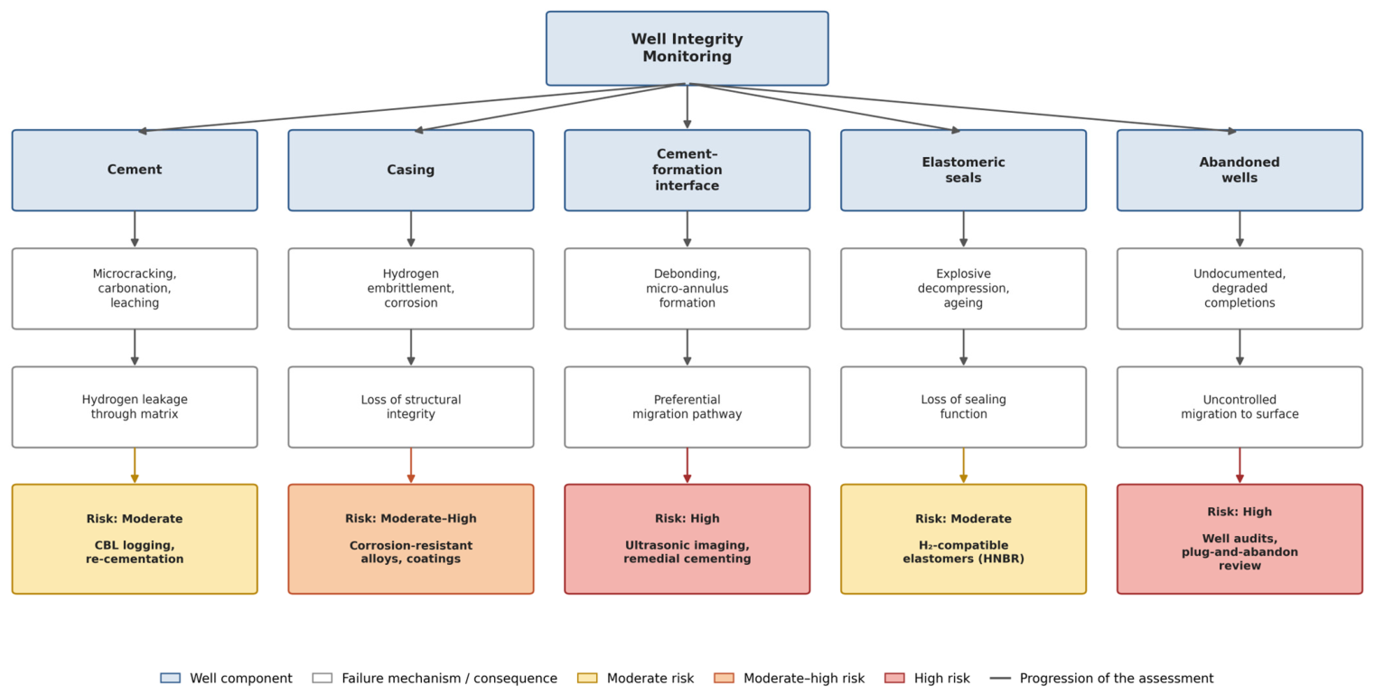
6.3. Mitigation Strategies

In case of detection of leakage or degradation, several mitigation strategies can be implemented: repair or re-cementation of damaged wells; reduction in pressure amplitudes during injection and withdrawal cycles to limit mechanical fatigue [10,45]; optimisation of cavity design, including geometry and depth, to reduce stresses on surrounding formations [6]; as well as the use of improved sealing materials specifically designed to resist hydrogen [37] (Figure 5). Beyond these component-level measures, UHS safety relies on a defence-in-depth approach, in which several independent barriers—the geological formation, the well completion, continuous monitoring, and emergency response procedures—act in series, so that the failure of any single barrier does not by itself result in an uncontrolled release. This layered approach, adapted from the natural gas and nuclear industries, is reflected in the decades-long safety record of existing underground gas storage operations, including hydrogen storage facilities such as Teesside, which has operated since the 1970s without a major containment failure [18,19]. Confidence in the operational safety of UHS is further supported by the ongoing development of hydrogen-specific codes and standards (ISO/TC 197, CEN/TC 268; see Section 11.2), by third-party integrity verification (e.g., cement bond logging, pressure testing), and by transparent public reporting of monitoring data, which are essential to building confidence among regulators, local communities and the general public that the risks associated with large-scale hydrogen storage can be identified, quantified and actively managed (Figure 5).

6.4. Summary

The implementation of appropriate monitoring and mitigation strategies significantly reduces the risks of leakage and ensures the sustainability of underground hydrogen storage. These strategies are particularly effective when they are integrated from the design phase of the project [6,45].

7. Thermodynamic and Transport Properties of Hydrogen in Porous Media

7.1. Equation of State and Phase Behaviour

Accurate prediction of hydrogen behaviour under reservoir conditions requires robust equations of state (EOS). The Peng–Robinson and Soave–Redlich–Kwong EOS are commonly employed in reservoir simulation, but their accuracy for hydrogen at high pressures and elevated temperatures has been questioned [114,115]. The deviation from ideal gas behaviour for hydrogen is less pronounced than for heavier hydrocarbons due to its low critical temperature (33.15 K) and critical pressure (12.97 atm), meaning that hydrogen exists as a supercritical fluid under virtually all subsurface storage conditions [116,117]. Across the typical operating envelope of UHS facilities (approximately 60–300 bar, 10–90 °C; see Table 3), hydrogen behaves as a near-ideal gas, with a compressibility factor Z generally in the range of 1.0–1.1, in contrast to natural gas or CO2, for which Z can deviate substantially below unity at comparable conditions [116]. This near-ideal behaviour reduces uncertainty in cushion gas and working gas volume calculations but does not eliminate it, since even small deviations in Z propagate into significant errors in deliverability estimates at field scale. A further thermodynamic consideration specific to hydrogen is its inverse Joule–Thomson effect at typical storage temperatures: unlike natural gas, which cools upon expansion, hydrogen warms slightly during rapid depressurisation (Joule–Thomson coefficient of approximately −0.03 K/bar near ambient conditions), which influences the thermal loading experienced by wellhead equipment, elastomeric seals and near-wellbore cement during high-rate withdrawal cycles [47,117]. Modified EOS incorporating quantum corrections, such as the Leachman equation, provide improved accuracy for hydrogen thermodynamic properties across wide pressure–temperature ranges and are increasingly used to couple reservoir-scale simulations with the cyclic thermal loading analyses discussed in Section 8 [47].

7.2. Multiphase Flow and Relative Permeability

In depleted reservoirs and aquifers, hydrogen coexists with formation water and residual hydrocarbons, creating complex multiphase flow regimes. Relative permeability curves for hydrogen–brine systems differ significantly from those of methane–brine or CO2–brine systems due to the lower viscosity and interfacial tension of hydrogen [48,49]. Experimental determination of hydrogen–brine relative permeabilities remains limited, and most reservoir simulations rely on analogies from natural gas data or empirical correlations such as the Brooks–Corey or van Genuchten models [118]. Pore-scale modelling of hydrogen–brine displacement offers a complementary route to constraining these functions [119]. Capillary pressure–saturation relationships for hydrogen are characterised by lower entry pressures compared to other gases, owing to the lower hydrogen–brine interfacial tension (approximately 50–72 mN/m at reservoir conditions compared to 20–50 mN/m for CO2–brine) [50,51]. Wettability alterations induced by hydrogen exposure of rock surfaces remain a subject of active research, with preliminary results suggesting that hydrogen may reduce the water-wetness of some mineral surfaces, potentially increasing residual trapping efficiency [120].

7.3. Viscous Fingering and Gravitational Segregation

The very low density and viscosity of hydrogen relative to formation water create conditions favourable to viscous fingering and gravity override during injection into porous media [52]. The mobility ratio between hydrogen and brine is typically unfavourable (M >> 1), leading to unstable displacement fronts that reduce sweep efficiency and can create preferential flow channels through the reservoir [53]. Gravitational segregation, driven by the large density contrast (Δρ ≈ 1000 kg/m3 between brine and hydrogen at depth), causes hydrogen to accumulate beneath the caprock, forming a thin gas cap that maximises the contact area with potential leakage pathways [54]. Simulation studies have demonstrated that reservoir heterogeneity, in particular the presence of high-permeability layers and structural traps, strongly influences the spatial distribution of hydrogen and the recovery efficiency during withdrawal cycles [55,56].

7.4. Geochemical Interactions

Hydrogen is a strong reducing agent that can drive geochemical reactions with reservoir minerals, formation fluids, and well materials. The reduction of iron-bearing minerals such as haematite (Fe2O3) and magnetite (Fe3O4) by hydrogen has been documented under reservoir conditions, potentially altering the pore structure and mineralogy of the host formation [61,62]. Sulphate reduction (abiotic and biotic) can produce hydrogen sulphide (H2S), which is both toxic and corrosive, posing additional challenges for gas-quality management and material compatibility [57,63]. Dissolution and precipitation reactions involving carbonate minerals may modify caprock porosity and permeability over extended storage periods, although the kinetics of these reactions under hydrogen-rich conditions remain poorly constrained [64,65]. These geochemical considerations underscore the need for comprehensive mineralogical and geochemical characterisation of candidate storage formations prior to hydrogen injection.

8. Geomechanical Modelling of Salt-Cavern Behaviour

Predicting reservoir-scale behaviour depends on hydrogen’s thermodynamic and transport properties, but storage performance also rests on how the host rock responds mechanically to repeated pressure cycling. This section addresses geomechanical modelling approaches that capture the time-dependent deformation, damage, and self-healing of salt caverns under hydrogen storage conditions.

8.1. Constitutive Models for Rock Salt

The mechanical behaviour of rock salt is characterised by time-dependent deformation (creep), dilatancy, damage, and self-healing, all of which are critical for assessing cavern stability and tightness under hydrogen storage conditions [23,24]. The most widely used constitutive models include the Norton power law for steady-state creep, the Munson–Dawson model for transient and steady-state creep, and the Cristescu model incorporating dilatancy and damage [25,121]. More advanced models, such as the Lux/Wolters model and the composite dilatancy model (CDM), capture the transition from compressive to dilatant behaviour and the progressive development of permeability in the damaged zone surrounding the cavern [122,123]. These constitutive models were developed and validated predominantly for near-monotonic or slowly varying stress histories: the Munson–Dawson formulation was originally calibrated against Waste Isolation Pilot Plant (WIPP) creep data under near-constant confining stress over multi-decadal timescales, and the classical Norton power law describes only steady-state creep rate as a function of stress, without an explicit time- or cycle-dependent damage variable. Their direct applicability to UHS is therefore not guaranteed: hydrogen storage caverns undergo daily-to-seasonal pressure cycling far more frequent than the loading histories these models were calibrated against, and neither the standard Munson–Dawson nor Norton formulations natively capture cycle-dependent phenomena such as reverse (inverse transient) creep upon unloading; the Bauschinger effect; or the progressive, hysteretic accumulation of microdamage over repeated cycles. Recognising this gap, recent studies have extended salt constitutive frameworks specifically for cyclic hydrogen operation: Chang and Ross [124] modelled the geomechanical stability of multiple interacting salt caverns under cyclic loading–unloading and identified inter-cavern stress-redistribution effects that single-cavern, monotonic-loading analyses do not capture, while other coupled thermo-hydro-mechanical-damage formulations incorporate explicit damage–healing coupling to represent the competition between cycle-induced microcracking and viscoplastic healing. Until such cyclic-specific extensions are more widely validated against long-duration hydrogen-cycling data, results obtained with the unmodified classical models should be interpreted as indicative rather than strictly predictive for UHS operating conditions.

8.2. Cavern Stability Criteria

Cavern stability is commonly assessed against two primary criteria: (i) the dilatancy criterion, which defines the stress state boundary beyond which microcracking initiates and permeability increases; and (ii) the minimum operating pressure, below which tensile stresses or excessive convergence may compromise cavern integrity [32,99]. The dilatancy boundary is typically expressed in terms of the stress invariants (mean stress and deviatoric stress) and depends on the confining pressure, temperature, and loading rate [23,125]. For hydrogen storage applications, the minimum cavern pressure must also account for the lower compressibility of hydrogen compared to natural gas, which results in larger pressure swings for equivalent energy throughput [126]. Maximum operating pressure is constrained by the lithostatic gradient and the fracture gradient of the caprock, typically limited to 80–85% of the lithostatic pressure at cavern casing shoe depth [99].

8.3. Cyclic-Loading Effects

Hydrogen storage operations involve repeated cycles of pressurisation (injection) and depressurisation (withdrawal), imposing cyclic mechanical loads on the cavern walls and surrounding salt [109,127]. Laboratory experiments on rock-salt specimens subjected to cyclic loading demonstrate progressive damage accumulation, manifested as increased acoustic emission activity, permeability enhancement, and accelerated creep rates [33,128]. The rate and amplitude of pressure cycling are key parameters: high-frequency cycling with large pressure amplitudes may accelerate damage beyond the self-healing capacity of the salt, whereas slower, smaller-amplitude cycles allow sufficient time for viscoplastic closure of micro-fractures [129]. Numerical simulations using coupled damage–creep models have been employed to optimise operating-pressure envelopes that balance storage capacity against long-term cavern stability [123,126].

8.4. Self-Healing and Permeability Recovery

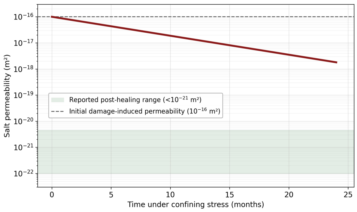
A distinctive property of rock salt is its capacity for self-healing, whereby damage-induced permeability is progressively recovered under sustained confining pressure [45,130]. The self-healing process involves recrystallisation and pressure solution at grain contacts, which close micro-fractures and restore the original low permeability of the salt [131,132]. Laboratory studies have demonstrated that permeability can be reduced by several orders of magnitude (from 10−16 to below 10−21 m2) within months to years under representative confining stresses [95,130]. However, the effectiveness of self-healing depends on the extent of initial damage, the presence of insoluble residues, and the sustained application of a confining stress exceeding the dilatancy boundary [131]. For hydrogen storage, the rapid cycling between injection and withdrawal may periodically reopen healed fractures, creating a dynamic equilibrium between damage and healing that must be captured in predictive models [123,129] (Figure 6).

8.5. Coupled Thermo-Hydro-Mechanical Modelling Frameworks

The creep, dilatancy and self-healing behaviours discussed above are not purely mechanical: cyclic hydrogen injection and withdrawal impose simultaneous thermal and pore-pressure transients that interact with the mechanical response, motivating a fully coupled thermo-hydro-mechanical (THM) or thermo-hydro-mechanical-chemical (THMC) treatment rather than a mechanics-only one. General-purpose THM coupling frameworks developed for other geo-energy and geo-engineering applications provide a methodological basis that has yet to be fully exploited for UHS: Abed and Sołowski [133] formulated a general set of coupled THM governing equations and a numerical implementation for unsaturated soils that is, in principle, transferable to porous-formation UHS; Rutqvist et al. [104] demonstrated a THMC framework linking mechanical deformation, fluid flow, heat transport and geochemistry for bentonite-sealed repository tunnels, illustrating how sealing-material behaviour (Section 4.2) can be embedded directly within the coupled formulation rather than treated separately. On the thermal side specifically, Kushnir et al. [134] modelled the temperature and pressure evolution within compressed-air storage caverns under cyclic operation, showing that thermal transients from rapid compression/expansion can be substantial and should not be neglected when assessing cyclic mechanical loading of the cavern wall—a consideration directly applicable to hydrogen caverns, where similarly rapid pressure cycling is expected. Adapting and validating this class of coupled THM/THMC formulations specifically for hydrogen—including hydrogen-specific sealing materials and cavern, mine and porous-formation geometries alike—is identified here as a methodological priority connecting the geomechanical, sealing-material and thermodynamic strands of this review.

9. Microbial Activity in Underground Hydrogen Storage

Beyond physical and mechanical factors controlling hydrogen containment, the subsurface environment introduces biological complexities that can significantly impact storage efficiency. This section examines microbial communities and their potential to metabolise stored hydrogen, reducing storage capacity and gas quality.

9.1. Subsurface Microbial Communities

Deep subsurface environments harbour diverse microbial communities capable of metabolising hydrogen as an electron donor [57,63]. The principal microbial groups relevant to underground hydrogen storage include sulphate-reducing bacteria (SRB), methanogenic archaea, acetogenic bacteria, and iron-reducing bacteria [58,135]. These organisms can utilise dissolved hydrogen in combination with available electron acceptors (sulphate, CO2, ferric iron) to drive metabolic reactions that consume stored hydrogen and produce undesirable by-products [57,59].

9.2. Metabolic Pathways and Gas-Quality Implications

The primary microbial reactions of concern in UHS are the following [16,57,135]:
4H2 + SO42− → H2S + 2H2O + 2OH
4H2 + CO2 → CH4 + 2H2O
4H2 + 2CO2 → CH3COOH + 2H2O
Equation (1) represents sulphate reduction, which is particularly problematic because H2S is both toxic and highly corrosive to steel infrastructure [63]. Equation (2) represents methanogenesis, which reduces the hydrogen purity of the withdrawn gas, potentially requiring costly purification steps [59,136]. Equation (3) represents acetogenesis. Field observations from the Lobodice underground gas storage facility in the Czech Republic documented significant hydrogen losses attributed to microbial methanogenesis, providing direct evidence of the operational relevance of these processes [60].
These field-scale losses have since been reproduced through process-based modelling: coupling geochemical and microbial kinetic formulations calibrated against the Lobodice dataset, Tremosa et al. [137] showed that a purely thermodynamic (equilibrium) description overpredicts hydrogen reactivity, and that a kinetically constrained, Monod-type microbial rate law is required to match the observed extent of methanogenesis—providing a validated, quantitative basis for forecasting hydrogen loss at other sites rather than relying on qualitative risk statements alone. More broadly, biogeochemical reactive-transport models spanning pore-to-reservoir scales, implemented in platforms such as PHREEQC, version 3, COMSOL, DuMuX and CMG-GEM are increasingly used to predict microbial hydrogen consumption and geochemical hydrogen loss under site-specific conditions, though a recent multi-scale review concludes that reservoir-scale predictions still cannot yet be fully validated against field data and that closer integration of laboratory-calibrated kinetics with reservoir simulation remains a priority [138].

9.3. Factors Controlling Microbial Activity

Microbial activity in the subsurface is governed by several environmental factors: temperature, salinity, pH, the availability of nutrients and electron acceptors, and the presence of biofilms on mineral surfaces [57,58]. Salt caverns are generally considered less susceptible to microbial contamination due to the extreme salinity of the brine (saturated NaCl, ≈300 g/L), which inhibits most microbial metabolisms [139]. However, halophilic and halotolerant microorganisms have been identified in salt deposits, and their potential to metabolise hydrogen under high-salinity conditions is an emerging area of investigation [140,141]. In depleted reservoirs and aquifers, where salinities are typically lower and nutrient availability higher, microbial hydrogen consumption can be significant, with reported losses ranging from 3% to over 17% of injected hydrogen volumes in some field and laboratory studies [57,60].

9.4. Mitigation of Microbial Risks

Strategies to mitigate microbial hydrogen consumption include site selection in formations with high salinity and high temperature (above 80 °C, which limits most mesophilic organisms), treatment of injection water with biocides, minimisation of the gas–water contact area through operational design, and the use of cushion gases that inhibit microbial activity [57,136]. Periodic monitoring of microbial populations through DNA/RNA analysis of produced water samples, combined with geochemical monitoring of H2S and CH4 concentrations, provides early warning of microbial proliferation [58,142].

9.5. Integration with Well Integrity and Overall Risk Assessment

Microbial activity should not be treated as an isolated biological curiosity but as a coupled contributor to the well-integrity and leakage risk picture developed in Section 5 and Section 6. Sulphate reduction (Equation (1)) generates H2S, which is both corrosive to carbon steel casing and tubing and toxic, directly compounding the well-related failure mechanisms summarised in Table 4; where formation water contacts uncoated metal, microbially generated H2S can therefore accelerate the same well-degradation pathways identified in Section 5.6 as the dominant risk factor in salt caverns and a major contributor in porous reservoirs. Methanogenesis (Equation (2)), by contrast, degrades gas quality rather than well integrity, translating into an economic rather than a safety risk and reinforcing the case for incorporating microbial gas-quality losses into the techno-economic assessments discussed in Section 12.2. Because microbial activity is itself storage-type-dependent—inhibited in the high-salinity brine of salt caverns but potentially significant under the lower-salinity, nutrient-richer conditions of depleted reservoirs and aquifers—it follows the same storage-type-dependent risk hierarchy established in Section 5.5 rather than constituting a separate, independent risk category. Geochemical monitoring of H2S and CH4 concentrations (Section 6.1, Table 5) should accordingly be interpreted jointly with well-integrity indicators, as part of a single coupled risk assessment, rather than as a standalone microbiological metric.

10. Case Studies of Existing Underground Hydrogen Storage Facilities

10.1. Teesside, United Kingdom

The Teesside facility, operated by Sabic (formerly ICI), represents one of the earliest and longest-running commercial hydrogen storage operations in salt caverns. Commissioned in the 1970s, the facility comprises three caverns at depths of approximately 350 m in the Permian Billingham Anhydrite Formation, with a combined storage volume of approximately 210,000 m3 and a working gas capacity of about 25 GWh [16,17]. The stored gas is nominally 95% hydrogen at pressures ranging from 24 to 50 bar. Over several decades of operation, the facility has demonstrated excellent containment performance, with no reported major integrity incidents, providing strong empirical evidence for the viability of hydrogen storage in salt formations [18,19] (Table 6).

10.2. Gulf Coast, United States

Three salt-cavern hydrogen storage facilities operate along the U.S. Gulf Coast in Texas and Louisiana, owned by Air Liquide, Praxair (now Linde), and ConocoPhillips [16,20]. The Clemens facility (Praxair) and the Moss Bluff facility (Air Liquide) store high-purity hydrogen in Jurassic salt domes at depths of 800–1200 m [20,21]. The Spindletop facility near Beaumont, Texas, operated by Air Liquide, has a working gas volume of approximately 906,000 m3 [19,22]. These facilities operate at pressures between 55 and 152 bar and serve as industrial buffer storage for petrochemical refineries and hydrogen pipeline networks. Their operational track record over several decades confirms the technical maturity of salt-cavern hydrogen storage and provides valuable data on cavern convergence rates, gas purity maintenance, and integrity monitoring practices [20,22].

10.3. Emerging Projects and Demonstrations

Several new UHS projects are under development globally, reflecting the growing strategic importance of large-scale hydrogen storage. The HyStock project in the Netherlands aims to develop a pilot salt-cavern hydrogen storage facility in the Zuidwending salt dome, with planned commissioning around 2026 [143]. The Bad Lauchstädt Energy Park in Germany is developing a former natural gas storage cavern for hydrogen, with a target volume of 50 million m3 and a planned demonstration phase integrating green hydrogen production with renewable energy sources [144,145]. The Advanced Clean Energy Storage (ACES) project in Delta, Utah, USA, represents one of the largest planned hydrogen storage facilities worldwide, with two salt caverns targeting 5500 GWh of storage capacity [146]. In the Middle East and North Africa region, geological assessments of salt diapirs in Morocco, Algeria, and Tunisia have identified several potentially suitable structures for UHS, although detailed feasibility studies remain at an early stage. A recent Morocco-focused study integrating rock-salt mechanical behaviour with UHS site-selection criteria has identified candidate salt formations in Moroccan basins, consistent with ongoing national pre-feasibility work such as the MELHY project [4]. By contrast, comparable peer-reviewed geological assessments for Algeria, Tunisia, Sub-Saharan Africa and the Asia-Pacific region remain largely absent from the literature; extending the kind of global inventory compiled by Sambo et al. [147] into a systematic, region-specific evaluation of salt, saline-aquifer and depleted-reservoir potential across these underexplored areas is identified here as a priority for future work.

10.4. Porous-Reservoir Demonstrations: Underground Sun Storage and Hychico

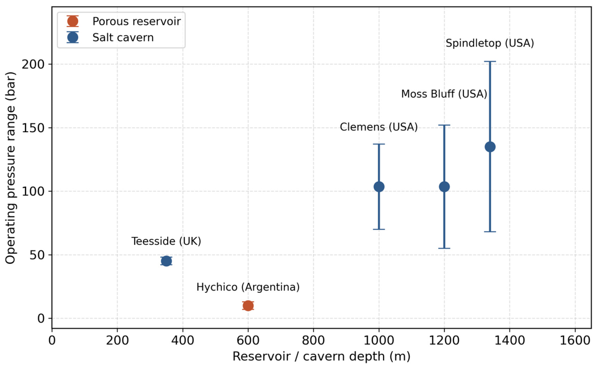
Beyond salt caverns, two operating porous-reservoir demonstrations provide direct evidence for UHS feasibility in depleted gas fields. The Underground Sun Storage facility (RAG Austria AG), commissioned in 2023 at Gampern, Upper Austria, converts a depleted natural gas reservoir at approximately 1000 m depth; its surface infrastructure integrates a solar/electrolysis hydrogen supply, a compressor station for reservoir injection, and dedicated wellhead monitoring equipment, and the facility has completed two full storage cycles of essentially pure hydrogen (around 500,000 m3 per cycle), confirming both containment integrity and hydrogen purity sufficient for pipeline injection [91]. The Hychico-Diadema pilot in Chubut, Argentina, operated between 2011 and 2015 at approximately 600 m depth and 1 MPa reservoir pressure, using a 2.3 km pipeline to link an on-site electrolyser HySTAT® to well F-160; its three-stage injection/withdrawal programme (alternating natural gas and hydrogen-blended gas) established baseline operating parameters and characterised in situ microbial response under real reservoir conditions, complementing the salt-cavern case studies above with porous-medium-specific operational evidence [147] (Figure 7).
Figure 7. Operating-pressure range plotted against depth for the real-world UHS facilities listed in Table 6, showing the consistently lower operating-pressure envelope of the shallower Teesside cavern relative to the deeper US Gulf Coast caverns, and the distinct porous-reservoir regime represented by Hychico.
Hydrogen 07 00116 g007
Table 6. Overview of existing and planned underground hydrogen storage facilities. Columns for operating pressure, reported operational performance, and data sources have been added to enable direct quantitative cross-comparison of storage scale, pressure regime, and operational status across salt-cavern and porous-reservoir projects.
FacilityLocationTypeDepth (m)CapacityStatusOperating PressureReported Performance/StatusSource
Teesside (ICI/Sabic)UKSalt cavern~350210,000 m3Operational since 1970s45 barContinuous operation since the 1970s with no significant hydrogen losses reported in the operator’s public record[16,20,148]
Clemens (Praxair/Linde)Texas, USASalt cavern~1000580,000 m3Operational70–137 barOperational since 1983; part of the established US Gulf Coast merchant hydrogen network[16,20,148]
Moss Bluff (Air Liquide)Texas, USASalt cavern~1200566,000 m3Operational55–152 barOperational since 2007; integrated with regional H2 pipeline grid[16,20,148]
Spindletop (Air Liquide)Texas, USASalt cavern~1340906,000 m3Operational68–202 barLargest of the three Gulf Coast caverns by volume; operational, integrated with regional H2 pipeline grid[16,20,148]
HyStockThe NetherlandsSalt cavern~1000PilotUnder developmentNot yet reported (pilot phase)First cavern-conversion trials ongoing; results not yet publicly reported[16,20,148]
Bad LauchstädtGermanySalt cavern~80050 Mm3DemonstrationNot yet reported (demonstration phase)Injection/withdrawal demonstration trials planned; results not yet publicly reported[16,20,148]
ACES DeltaUtah, USASalt cavern~11005500 GWhUnder constructionNot yet reported (under construction)Construction in progress; targeting large-scale seasonal storage for regional electrolytic hydrogen[16,20,148]
Underground Sun Storage (RAG), GampernAustriaPorous depleted gas reservoir~1000~500,000 m3 H2 per cycleTwo storage cycles completed (pilot)Not publicly disclosed100% H2 storage/withdrawal feasibility confirmed over two full cycles; H2 purity met pipeline injection specifications[91]
Hychico-Diadema pilotArgentinaPorous depleted gas reservoir~60010% H2 blend (pilot scale)Completed pilot (2011–2015)~10 bar (1 MPa)Three-stage injection/withdrawal programme completed; established baseline operating parameters and microbial behaviour under real reservoir conditions[147]

11. Regulatory Frameworks and Safety Standards

11.1. Existing Regulatory Landscape

The regulatory framework for underground hydrogen storage is still evolving and remains fragmented across jurisdictions. Most existing regulations are derived from natural gas storage regulations and CO2 geological storage directives, with hydrogen-specific provisions being progressively introduced [84,85]. In the European Union, the Gas Storage Directive (2009/73/EC) provides the general framework for underground gas storage, but does not explicitly address hydrogen [86]. The EU Hydrogen Strategy (2020) and the revised Renewable Energy Directive (RED III) recognise the need for hydrogen-specific storage regulations, including permitting procedures, safety requirements, and environmental impact assessment protocols [3,87]. In the United States, underground hydrogen storage is regulated at the federal level by the Pipeline and Hazardous Materials Safety Administration (PHMSA) and at the state level by individual oil and gas commissions [88].

11.2. Safety Standards and Risk Assessment

Several international and national standards bodies are developing or adapting standards for hydrogen storage safety. The ISO/TC 197 (Hydrogen Technologies) and CEN/CLC/JTC 6 (Hydrogen in Energy Systems) technical committees are actively working on standards relevant to underground hydrogen storage [149]. Key safety considerations include maximum allowable operating pressure (MAOP), minimum operating pressure, cavern well spacing, gas-quality specifications, and emergency response protocols [84,99]. Quantitative risk assessment (QRA) methodologies adapted from the oil and gas industry, including bowtie analysis, layers of protection analysis (LOPA), and consequence modelling, are being applied to UHS facilities [71,72]. The definition of safety zones around storage wells and surface facilities must account for the specific dispersion characteristics of hydrogen, which, due to its low density and high diffusivity, disperses more rapidly than natural gas but has a wider flammability range (4–75% v/v in air compared to 5–15% for methane) [116,150].

11.3. Environmental Regulatory Requirements

Environmental regulations for UHS typically require environmental impact assessments (EIA), groundwater monitoring programmes, and decommissioning plans [84,85]. The potential environmental impacts of hydrogen leakage include the alteration of soil chemistry and microbial communities, contamination of shallow aquifers, and indirect effects on atmospheric chemistry (hydrogen has an indirect global warming potential through its effect on the atmospheric lifetime of methane and stratospheric ozone) [151,152]. Regulatory frameworks must therefore address both the subsurface containment aspects and the surface and atmospheric consequences of potential hydrogen releases [85].

11.4. Regional Comparative Overview

Beyond the EU and US frameworks discussed above, regulatory attention to hydrogen is intensifying in Asia and the MENA region, though largely at the level of national hydrogen strategies rather than dedicated underground storage regulation. Japan’s Hydrogen Society Promotion Act, enacted in May 2024, establishes a business-plan approval regime and subsidy mechanisms for low-carbon hydrogen supply and infrastructure, but does not yet set out storage-specific technical provisions [153]. South Korea amended its Hydrogen Economy Promotion and Hydrogen Safety Management Act in November 2023 to introduce a Clean Hydrogen Certification System and Clean Hydrogen Portfolio Standards, focused on production carbon intensity and offtake rather than subsurface storage [154]. In the United Arab Emirates, the Low-Carbon Hydrogen Regulatory Framework has remained in draft form since October 2022, and while the national Hydrogen Strategy explicitly identifies underground storage—including salt caverns—as a future need, it acknowledges that considerable development is still required before this becomes operationally feasible [155]. In Morocco, storage-relevant activity remains at the pre-feasibility stage, exemplified by the MELHY project and by site-selection studies such as El Aichouni et al. [4]. Overall, no jurisdiction outside the EU and US currently regulates underground hydrogen storage as a distinct activity; regulatory development is proceeding faster for hydrogen production, certification and trade than for subsurface storage itself. Table 7 summarises this comparative regulatory landscape. At the global level, this regulatory gap is significant: the International Energy Agency and the Hydrogen Council both identify underground storage as essential infrastructure for hydrogen trade and seasonal balancing, yet no international body currently issues UHS-specific technical standards, leaving national and regional frameworks (Table 7) as the only operative layer of governance. This mismatch between global strategic recognition and regional regulatory fragmentation is itself a barrier to cross-border UHS investment and should be treated as a policy priority alongside the technical research priorities identified in Section 14.2.

12. Environmental and Techno-Economic Considerations

12.1. Environmental Impact of Underground Hydrogen Storage

The environmental footprint of UHS extends beyond the storage operation itself and encompasses the full life cycle from cavern development (including solution mining and brine disposal) through operation to decommissioning [156,157]. Solution mining of salt caverns produces large volumes of saturated brine that must be managed through pipeline disposal to the sea, deep-well injection, or beneficial use in the chemical industry [158]. The energy consumption associated with hydrogen compression for injection (typically to pressures of 50–200 bar) represents a significant parasitic load that reduces the round-trip efficiency of the storage system [159]. Life-cycle assessment (LCA) studies have estimated the greenhouse gas emissions associated with salt-cavern hydrogen storage at 0.2–0.5 kg CO2-eq/kg H2 stored, which is substantially lower than compressed gas storage above ground [81,82]. Beyond these direct physical and life-cycle impacts, environmental impact assessments for UHS should also account for social acceptance and cumulative effects. Public perception research on hydrogen technologies indicates that awareness is often high but technical understanding limited, with concerns concentrated on the perceived safety of infrastructure sited near residential areas [160]. Systematic risk-perception studies further show that the public tends to underweight accidental risks from hydrogen infrastructure relative to systemic risks such as security of supply, underscoring the need for transparent, two-way stakeholder engagement rather than one-directional risk communication [161]. For UHS specifically, early and sustained community consultation—covering site selection, brine-disposal routes and monitoring transparency—has been identified as important for securing a social licence to operate, particularly given legacy concerns carried over from underground gas and CO2 storage projects [162]. Cumulative environmental effects, including the combined footprint of solution mining, compression energy demand and land-use change at hubs hosting multiple caverns, remain comparatively understudied and warrant integration into future life-cycle and social-impact assessments of UHS deployment.

12.2. Techno-Economic Assessment

The economic viability of UHS depends on several factors, including cavern development costs, compression energy costs, cushion gas requirements, and the value of the stored hydrogen [77,159]. Capital costs for salt-cavern development are estimated at 30–100 EUR/MWh of working gas capacity, depending on cavern size, depth, and geological conditions [34,78]. Cushion gas, which represents 20–40% of the total cavern volume and is not recovered during normal operations, constitutes a significant upfront investment, particularly given the high cost of green hydrogen [79,159]. Acar et al. [163] evaluated four stationary hydrogen storage technologies using an interval-valued intuitionistic fuzzy AHP (IVIF-AHP) framework, assigning criterion weights of 31% (environmental), 26% (technical), 23% (economic) and 20% (social); underground hydrogen storage scored 0.453 on a normalised sustainability index, second only to compressed gas (0.487) and significantly ahead of metal hydride (0.301) and cryogenic liquid hydrogen options.

12.3. Levelised Cost of Storage

The levelised cost of hydrogen storage (LCOHS) in salt caverns has been estimated in the range of 0.5–2.0 EUR/kg H2, depending on assumptions regarding cycling frequency, cavern utilisation, and electricity costs for compression [77,78,80]. This is significantly lower than above-ground compressed gas storage (5–15 EUR/kg H2) and comparable to or lower than liquid hydrogen storage, making underground storage the most cost-effective option for large-scale, long-duration hydrogen storage [159,164]. However, the LCOHS is highly sensitive to the number of injection–withdrawal cycles per year; seasonal storage with one or two cycles per year results in higher per-unit costs than weekly or daily cycling applications [77,80]. Continued cost reductions are expected as the technology matures and the scale of deployment increases, with learning rates estimated at 10–15% per doubling of cumulative installed capacity [165].

13. CCUS–UHS Integration Perspectives

13.1. Concept and Rationale

An emerging mitigation avenue is the substitution of conventional cushion gas by CO2 in underground gas storage facilities, a concept with direct applicability to UHS. CO2 cushion gas replacement represents a frontier technology in CCUS, as CO2’s high density and compressibility reduce retention losses while enabling large-scale carbon sequestration within the storage reservoir itself [73]. For UHS, this represents a dual-function configuration: CO2 injected as a cushion gas provides the pressure support required during withdrawal cycles while being permanently sequestered in the geological formation.
The integration of carbon capture, utilisation and storage (CCUS) with underground hydrogen storage represents an emerging frontier with significant potential for synergies [73,74]. The fundamental concept involves using CO2 as a cushion gas in UHS facilities, thereby combining the pressure-support function of cushion gas with permanent geological sequestration of CO2 [73,75]. This dual-function configuration could substantially reduce the cost of cushion gas (by replacing expensive hydrogen with captured CO2) while simultaneously providing a carbon sequestration pathway, creating value at both ends of the decarbonisation chain [73].

13.2. Technical Challenges

Key technical challenges for CCUS–UHS integration include: (i) preventing premature CO2 breakthrough into the hydrogen working gas stream, which would contaminate the produced hydrogen and require additional purification; (ii) characterising the mixing and dispersion behaviour at the CO2–H2 interface under cyclic pressure conditions; (iii) understanding the long-term geochemical interactions between CO2, H2, formation brine, and reservoir minerals; and (iv) assessing the geomechanical stability of the formation under the combined influence of two injected gases with different thermophysical properties [73,74,75]. Numerical simulations suggest that gravitational segregation, driven by the large density contrast between CO2 (supercritical density 400–800 kg/m3) and H2 (10–40 kg/m3 at storage conditions), can help maintain separation between the cushion and working gases, but the effectiveness of this separation under realistic cycling conditions requires further investigation [56,76].

13.3. Potential Benefits and Sustainability Implications

From a sustainability perspective, CCUS–UHS integration offers several potential benefits. The replacement of hydrogen cushion gas by CO2 could reduce the capital cost of UHS by 15–30%, depending on the cavern configuration and the cost differential between H2 and captured CO2 [73,166]. Permanent sequestration of CO2 within the storage formation would generate carbon credits under emissions trading schemes, further improving the economic case for integrated operations [167]. The environmental performance of UHS, already favourable compared to above-ground alternatives, would be further enhanced by the net carbon-negative contribution of the sequestered CO2 [73,163]. However, these benefits must be weighed against the additional technical complexity, monitoring requirements, and regulatory challenges associated with co-locating hydrogen storage and CO2 sequestration in the same geological formation [74].

14. Scientific Gaps and Research Perspectives

14.1. Limitations of Current Knowledge

Despite recent progress, several scientific gaps remain regarding the sealing of underground hydrogen storage. In particular, the long-term behaviour of sealing materials in the presence of hydrogen remains insufficiently documented [37,42], the cumulative effects of pressure cycles on microcracking and permeability of rocks and cements are still poorly understood [10,45,128], hydrogen–rock–fluid interactions in depleted aquifers and reservoirs require further study [1,2,61], and the quantitative impact of microbial hydrogen consumption on storage efficiency needs better characterisation under field-relevant conditions [57,60]. Furthermore, the multi-scale nature of hydrogen transport—from molecular diffusion through nanopores to advective flow through fracture networks—demands modelling approaches that bridge scales from the pore level to the reservoir level [56,93].

14.2. Future Research Needs

Future research should focus on long-term experimental studies of hydrogen diffusion and permeability in well materials under realistic cyclic-loading conditions [37,42]; the development of advanced multiphysical models integrating geomechanics, multiphase flow, geochemistry, and microbial kinetics [14,83,135]; the optimisation of saline cavity design and operation strategies to minimise leakage risks while maximising storage capacity and cycling efficiency [6,45,126]; the comprehensive characterisation of hydrogen–brine relative permeabilities and capillary pressures across a range of rock types and conditions [48,49,50]; the development and validation of hydrogen-resistant cement and sealant formulations for well construction and remediation [43,46]; the establishment of standardised testing protocols and performance criteria for UHS materials and systems [84,149]; the adaptation of existing approaches to regional contexts, particularly for North Africa and the Middle East, where geological data remain limited and salt diapir provinces may offer significant UHS potential; and the investigation of CCUS–UHS co-design as a priority axis for integrated energy infrastructure development [73,74].
To make these priorities actionable rather than a general wish-list, we rank them explicitly. Highest priority, addressable within 2–3 years with existing infrastructure: (i) standardised, cyclic (not monotonic) testing protocols for well cement and casing steel under realistic seasonal injection–withdrawal schedules, building directly on the framework proposed in Section 14.4; and (ii) field-scale validation of fibre-optic and other high-sensitivity monitoring technologies at an operating UHS site, since laboratory detection limits (Section 6.1) remain unvalidated in the field. Medium priority, requiring multi-year field campaigns: (iii) coupled thermo-hydro-mechanical-chemical models validated against field rather than purely laboratory data (Section 8.5); and (iv) systematic geological characterisation of UHS potential in North Africa, the Middle East, and other underexplored regions (Section 11.4), where data scarcity rather than unfavourable geology is currently the limiting factor. Lower priority but strategically important: (v) CCUS-UHS co-design studies, which remain largely conceptual (Section 3.6) and require pilot-scale demonstration before they can inform investment decisions.

14.3. Contribution of Numerical Modelling

Numerical modelling appears to be an essential tool for filling these gaps. Multiphysical simulations allow to evaluate the impact of geological and operational parameters on waterproofing and to anticipate the long-term storage behaviour [14,83]. Coupled thermo-hydro-mechanical-chemical (THMC) models are needed to capture the full complexity of hydrogen storage processes, including thermal effects during injection and withdrawal, pore-pressure evolution, mechanical deformation and damage of the host formation, and geochemical reactions [35,36,61]. Machine learning and data-driven approaches are increasingly being explored to complement physics-based models, particularly for real-time monitoring data interpretation, anomaly detection, and predictive maintenance scheduling [168,169]. These approaches constitute a solid basis for future thesis work integrating detailed numerical simulations with experimental validation and field-scale monitoring data. To date, most published UHS numerical studies couple only two or three of these physics domains—for example, multiphase flow and geomechanics [54,56]—rather than a fully integrated THMC formulation, and model validation has relied predominantly on laboratory-scale or synthetic benchmark data rather than field monitoring records [89]. Extending coupled THMC formulations to jointly capture hydrogen diffusion, pressure-cycle-induced microcracking and cement degradation, and validating them against both laboratory and field data, is identified here as a priority for improving predictive confidence in UHS integrity assessment.

14.4. Toward Standardised Testing Protocols: A Proposed Framework

No dedicated, hydrogen-specific testing standard yet exists for qualifying well steels, cements and elastomer seals under UHS conditions, forcing operators and researchers to rely on standards developed for other applications. Building on the best available science, three existing standard frameworks can be adapted, with explicit modifications, as a starting point for UHS-specific protocols: ISO 11114-4 [170] (hydrogen-embrittlement testing of steels for gas cylinders) for tubulars and casing, API RP 10B-2 [171] (testing of well cements) combined with the cyclic-exposure methodology recently demonstrated for hydrogen-cured cement [89], and ASTM D471 [172] (rubber compatibility with liquids), adapted from liquid to gaseous exposure, for elastomer seals. Table 8 outlines a draft framework indicating, for each material class, the standard(s) providing the closest existing basis, the modifications needed to represent UHS operating conditions, and the type of performance criterion that should be established. Because hydrogen-specific pass/fail thresholds have not yet been validated through inter-laboratory studies, the criteria are expressed qualitatively rather than as fixed numerical limits; quantitative thresholds should be defined by standards bodies (e.g., ISO/TC 197, API) once sufficient round-robin testing data are available. This framework is offered as a starting point for the standardisation effort called for throughout this review, rather than as a finished protocol.

15. Conclusions

Sealing sits at the heart of any safe, durable UHS project. As this review has shown, containment performance is set jointly by hydrogen’s physico-chemical properties, the host geology, and well integrity. The small molecular size, high diffusivity, low viscosity, and chemical reactivity of hydrogen create unique challenges that distinguish UHS from conventional underground gas storage. To move beyond a descriptive inventory of UHS-related topics toward a genuinely critical assessment, this review is deliberately organised around dominant failure mechanisms and their relative importance across storage types: well integrity is identified as the primary risk driver in salt caverns, while caprock heterogeneity and legacy wells dominate in porous formations (Section 5.5); classical geomechanical creep models are critically assessed for their limitations under cyclic hydrogen loading rather than simply catalogued (Section 8.1); and microbial hydrogen consumption is explicitly integrated into this same well-integrity and techno-economic risk picture rather than treated as an isolated subsection (Section 9.5).
Salt caverns remain the most reliable option, owing to their very low permeability and their capacity for self-healing [6,45]. The viscoplastic behaviour of rock salt, characterised by steady-state creep and the capacity for damage recovery through recrystallisation and pressure solution, provides a natural containment mechanism that is unmatched by other geological formations. However, successful storage relies heavily on the integrity of wells, identified as the main point of vulnerability [37]. Historical data from oil and gas operations, combined with emerging evidence from existing hydrogen storage facilities, confirm that well-related failures represent the most probable leakage pathway and therefore demand the highest level of engineering attention.
The thermodynamic and transport properties of hydrogen in porous media introduce additional complexities for reservoir-based storage, including unfavourable mobility ratios, viscous fingering, gravitational segregation, and geochemical interactions with formation minerals and fluids. Microbial activity represents a further source of hydrogen loss and gas-quality degradation, particularly in lower-salinity formations where diverse subsurface microbial communities can actively metabolise stored hydrogen.
The implementation of appropriate monitoring strategies, including advanced techniques such as distributed fibre-optic sensing, InSAR, and microseismic monitoring, combined with the development of hydrogen-resistant sealing materials, are essential to limit the risks of leakage. The emerging concept of CCUS–UHS integration, using CO2 as a cushion gas, offers promising synergies for cost reduction and carbon sequestration, although significant technical challenges related to gas mixing and geochemical stability remain to be addressed.
From a regulatory perspective, the framework for underground hydrogen storage is evolving rapidly but remains incomplete, with a need for hydrogen-specific standards covering design, operation, monitoring, and decommissioning. Techno-economic analyses confirm that underground storage in salt caverns offers the most cost-effective solution for large-scale, long-duration hydrogen storage, with levelised costs significantly below above-ground alternatives.
Finally, this review constitutes a solid scientific basis for future numerical and experimental work, in particular multiphysics simulation studies dedicated to the evaluation of the sealing of underground storage of green hydrogen. Priority research areas include long-term material testing under cyclic hydrogen exposure, the development of coupled THMC models bridging pore-to-reservoir scales, the comprehensive characterisation of hydrogen–brine–rock interactions, and regional feasibility assessments for emerging UHS prospects in North Africa and other underexplored regions.

Author Contributions

Conceptualization, H.T. and S.K.; methodology, H.T.; formal analysis, H.T.; investigation, H.T.; resources, H.T. and S.K.; data curation, H.T.; writing—original draft preparation, H.T.; writing—review and editing, H.T., L.O. and S.K.; visualization, H.T.; supervision, S.K.; project administration, L.O. All authors have read and agreed to the published version of the manuscript.

Funding

This research received no external funding.

Data Availability Statement

No new data were created in this study; data sharing is not applicable to this article, as it is a critical literature review.

Acknowledgments

During the preparation of this manuscript, the authors used Claude (Anthropic, Claude Opus 5) for language editing and proofreading, and Gemini (Gemini 3.5, Google) to assist in screening full-text source documents held by the authors. All literature was obtained and read by the authors; AI tools were not used to identify or generate references. The authors take full responsibility for the content of this publication.

Conflicts of Interest

The authors declare no conflict of interest.

Abbreviations

ACESAdvanced Clean Energy Storage
AHP/IVIF-AHP(Interval-Valued Intuitionistic Fuzzy) Analytic Hierarchy Process
CBLCement Bond Log
CCUSCarbon Capture, Utilisation and Storage
CDMComposite Dilatancy Model
CENEuropean Committee for Standardization
DASDistributed Acoustic Sensing
DFOSDistributed Fibre-Optic Sensing
DNA/RNADeoxyribonucleic Acid/Ribonucleic Acid
DTSDistributed Temperature Sensing
ECEuropean Commission
EIAEnvironmental Impact Assessment
EOSEquation of State
EUEuropean Union
EUREuro
GW/GWhGigawatt/Gigawatt-hour
HICHydrogen-Induced Cracking
HNBRHydrogenated Nitrile Butadiene Rubber
ICIImperial Chemical Industries
ISOInternational Organization for Standardization
LCALife-Cycle Assessment
LCOHSLevelised Cost of Hydrogen Storage
LOPALayers of Protection Analysis
LRCsLined Rock Caverns
MAOPMaximum Allowable Operating Pressure
MENAMiddle East and North Africa
MPaMegapascal
NBRNitrile Butadiene Rubber
PRAProbabilistic Risk Assessment
QRAQuantitative Risk Assessment
REDRenewable Energy Directive
SRBSulphate-Reducing Bacteria
TCTechnical Committee
THMThermo-Hydro-Mechanical
THMCThermo-Hydro-Mechanical-Chemical
UHSUnderground Hydrogen Storage
USAUnited States of America

References

  1. Zivar, D.; Kumar, S.; Foroozesh, J. Underground hydrogen storage: A comprehensive review. Int. J. Hydrogen Energy 2021, 46, 23436–23462. [Google Scholar] [CrossRef] [Scilit]
  2. Heinemann, N.; Booth, M.G.; Haszeldine, R.S.; Wilkinson, M.; Scafidi, J.; Edlmann, K. Hydrogen storage in porous geological formations—Onshore play opportunities in the midland valley (Scotland, UK). Int. J. Hydrogen Energy 2018, 43, 20861–20874. [Google Scholar] [CrossRef] [Scilit]
  3. European Commission. A Hydrogen Strategy for a Climate-Neutral Europe; COM(2020) 301 final; European Commission: Brussels, Belgium, 2020. [Google Scholar]
  4. El Aichouni, I.; Mridekh, A.; Nabil, N.; Rachidi, S.; El Hamraoui, H.; El Mansouri, B.; Essalih, A. A review of salt mechanical behavior, stability and site selection of underground hydrogen storage in salt cavern—Moroccan case. J. Energy Storage 2025, 131, 115813. [Google Scholar] [CrossRef] [Scilit]
  5. Bouchaou, L.; Ait brahim, Y. Introduction to Special Issue “Climate Variability, Change and Impact in Southern Morocco: Evidence and Understanding”. Front. Sci. Eng. 2021, 11, 5–8. Available online: https://revues.imist.ma/index.php/fsejournal/issue/view/1891 (accessed on 27 April 2026).
  6. Crotogino, F.; Huebner, S.; Brasseur, T. Large-scale hydrogen underground storage for securing future energy supplies. In Proceedings of the 18th World Hydrogen Energy Conference, Essen, Germany, 16–20 May 2010. [Google Scholar]
  7. IEA. The Future of Hydrogen: Seizing Today’s Opportunities; International Energy Agency: Paris, France, 2019. [Google Scholar] [CrossRef] [Scilit]
  8. Lord, A.S.; Kobos, P.H.; Borns, D.J. Geologic storage of hydrogen: Scaling up to meet city transportation demands. Int. J. Hydrogen Energy 2014, 39, 15570–15582. [Google Scholar] [CrossRef] [Scilit]
  9. Amid, A.; Mignard, D.; Wilkinson, M. Seasonal storage of hydrogen in a depleted natural gas reservoir. Int. J. Hydrogen Energy 2016, 41, 5549–5558. [Google Scholar] [CrossRef] [Scilit]
  10. Panfilov, M. Underground and pipeline hydrogen storage. Compend. Hydrogen Energy 2016, 2, 91–115. [Google Scholar] [CrossRef] [Scilit]
  11. Tarkowski, R. Underground hydrogen storage: Characteristics and prospects. Renew. Sustain. Energy Rev. 2019, 105, 86–97. [Google Scholar] [CrossRef] [Scilit]
  12. Tang, X.; Bai, X.; Wang, Y.; Li, X.; Zhang, F.; Wang, L.; Zhang, Z.; Wu, Y.; Yang, Q.; Ren, Q.; et al. In situ synthesis of copper-based mordenite for nitrogen/methane sieving. Nat. Commun. 2025, 16, 8065. [Google Scholar] [CrossRef] [Scilit] [PubMed]
  13. Al-Shafi, M.; Massarweh, O.; Abushaikha, A.S.; Bicer, Y. A review on underground gas storage systems: Natural gas, hydrogen and carbon sequestration. Energy Rep. 2023, 9, 6251–6266. [Google Scholar] [CrossRef] [Scilit]
  14. Wang, T.; Yang, C.; Ma, H.; Daemen, J.J.K.; Wu, H. Safety evaluation of salt caverns for hydrogen storage. Renew. Energy 2024, 210, 574–588. [Google Scholar] [CrossRef] [Scilit]
  15. Reitenbach, V.; Ganzer, L.; Albrecht, D.; Hagemann, B. Influence of added hydrogen on underground gas storage: A review of key issues. Environ. Earth Sci. 2015, 73, 6927–6937. [Google Scholar] [CrossRef] [Scilit]
  16. Bai, M.; Song, K.; Sun, Y.; He, M.; Li, Y.; Sun, J. An overview of hydrogen underground storage technology and prospects in China. J. Pet. Sci. Eng. 2014, 124, 132–136. [Google Scholar] [CrossRef] [Scilit]
  17. Allen, R.D.; Doherty, T.J.; Fossum, A.F. Geotechnical Issues and Guidelines for Storage of Compressed Air in Solution-Mined Salt Cavities; Pacific Northwest National Laboratory: Richland, WA, USA, 1982; PNL-4242.
  18. Tarkowski, R.; Uliasz-Misiak, B. Towards underground hydrogen storage: A review of barriers. Renew. Sustain. Energy Rev. 2022, 162, 112451. [Google Scholar] [CrossRef] [Scilit]
  19. Stone, H.B.J.; Veldhuis, I.; Richardson, R.N. Underground Hydrogen Storage in the UK. Geol. Soc. Lond. Spec. Publ. 2009, 313, 217–226. [Google Scholar] [CrossRef] [Scilit]
  20. Leith, W. Geologic and Engineering Constraints on the Feasibility of Clandestine Nuclear Testing by Decoupling in Large Underground Cavities; U.S. Geological Survey Open-File Report 01-28; U.S. Geological Survey: Reston, VA, USA, 2001; 43p. [CrossRef] [Scilit]
  21. Foh, S.E.; Novil, M.; Rockar, E.; Randolph, P. Underground Hydrogen Storage: Final Report; Brookhaven National Laboratory: New York, NY, USA, 1979; p. BNL 51275. [CrossRef] [Scilit]
  22. Panfilov, M.; Gravier, G.; Fillacier, S. Underground storage of H2 and H2–CO2–CH4 mixtures. In Proceedings of the 10th European Conference on the Mathematics of Oil Recovery, Amsterdam, The Netherlands, 4–7 September 2006. [Google Scholar] [CrossRef] [Scilit]
  23. Carter, N.L.; Hansen, F.D. Creep of rocksalt. Tectonophysics 1983, 92, 275–333. [Google Scholar] [CrossRef] [Scilit]
  24. Hunsche, U.; Hampel, A. Rock salt—The mechanical properties of the host rock material for a radioactive waste repository. Eng. Geol. 1999, 52, 271–291. [Google Scholar] [CrossRef] [Scilit]
  25. Munson, D.E.; Dawson, P.R. SAND79–1853; Constitutive Model for the Low Temperature Creep of Salt (with Application to WIPP); Sandia National Laboratories: Albuquerque, NM, USA, 1979.
  26. Caglayan, D.G.; Weber, N.; Heinrichs, H.U.; Linßen, J.; Robinius, M.; Kukla, P.A.; Stolten, D. Technical potential of salt caverns for hydrogen storage in Europe. Int. J. Hydrogen Energy 2020, 45, 6793–6805. [Google Scholar] [CrossRef] [Scilit]
  27. Muhammed, N.S.; Haq, M.B.; Al Shehri, D.; Al-Ahmed, A.; Rahman, M.M.; Zaman, E. A review on underground hydrogen storage: Insight into geological sites, influencing factors and future outlook. Energy Rep. 2022, 8, 461–499. [Google Scholar] [CrossRef] [Scilit]
  28. Cosenza, P.; Ghoreychi, M.; Bazargan-Sabet, B. In situ rock salt permeability measurement for long term safety assessment of storage. Int. J. Rock. Mech. Min. Sci. 1999, 36, 509–526. [Google Scholar] [CrossRef] [Scilit]
  29. Popp, T.; Kern, H.; Schulze, O. Evolution of dilatancy and permeability in rock salt during hydrostatic compaction and triaxial deformation. J. Geophys. Res. 2001, 106, 4061–4078. [Google Scholar] [CrossRef] [Scilit]
  30. Hildenbrand, A.; Schlömer, S.; Krooss, B.M. Gas breakthrough experiments on fine-grained sedimentary rocks. Geofluids 2002, 2, 3–23. [Google Scholar] [CrossRef] [Scilit]
  31. Li, S.; Dong, M.; Li, Z.; Huang, S.; Qing, H.; Nickel, E. Gas breakthrough pressure for hydrocarbon reservoir seal rocks: Implications for the security of long-term CO2 storage in the Weyburn field. Geofluids 2005, 5, 326–334. [Google Scholar] [CrossRef] [Scilit]
  32. DeVries, K.L.; Mellegard, K.D.; Callahan, G.D. Salt damage criterion proof-of-concept research. In Proceedings of the SMRI Fall Meeting, Nancy, France, 2–5 October 2005. [Google Scholar]
  33. Häupel, K.; Kamlot, P.; Schulze, O. The dilatancy concept—A basis for the assessment of long-term tightness of natural salt barriers. In Proceedings of the 6th Conference on the Mechanical Behaviour of Salt, Hannover, Germany, 22–25 May 2007. [Google Scholar]
  34. Simon, J.; Ferriz, A.M.; Correas, L.C. HyUnder—Hydrogen underground storage at large scale: Case study Spain. Energy Procedia 2015, 73, 136–145. [Google Scholar] [CrossRef] [Scilit]
  35. Rutqvist, J. The geomechanics of CO2 storage in deep sedimentary formations. Geotech. Geol. Eng. 2012, 30, 525–551. [Google Scholar] [CrossRef] [Scilit]
  36. Hou, Z. Mechanical and hydraulic behavior of rock salt in the excavation disturbed zone around underground facilities. Int. J. Rock. Mech. Min. Sci. 2003, 40, 725–738. [Google Scholar] [CrossRef] [Scilit]
  37. Guo, L.; Hu, R.; Zhong, C.; Wang, X.; Liu, J.; Wang, X. N-doped and sulfur vacancy-rich TiO2@SnS2 nanoporous arrays for the plasmonic photocatalytic H2 evolution. Int. J. Hydrogen Energy 2023, 48, 17177–17186. [Google Scholar] [CrossRef] [Scilit]
  38. King, G.E.; King, D.E. Environmental risk arising from well-construction failure—Differences between barrier and well failure, and estimates of failure frequency across common well types, locations, and well age. SPE Prod. Oper. 2013, 28, 323–344. [Google Scholar] [CrossRef] [Scilit]
  39. Davies, R.J.; Almond, S.; Ward, R.S.; Jackson, R.B.; Adams, C.; Worrall, F.; Herringshaw, L.G.; Gluyas, J.G.; Whitehead, M.A. Oil and gas wells and their integrity: Implications for shale and unconventional resource exploitation. Mar. Pet. Geol. 2014, 56, 239–254. [Google Scholar] [CrossRef] [Scilit]
  40. Gangloff, R.P.; Somerday, B.P. Gaseous Hydrogen Embrittlement of Materials in Energy Technologies; Woodhead Publishing: New Delhi, India, 2012; Volume 1. [Google Scholar] [CrossRef] [Scilit]
  41. Lynch, S.P. Hydrogen embrittlement phenomena and mechanisms. Corros. Rev. 2012, 30, 105–123. [Google Scholar] [CrossRef] [Scilit]
  42. Kutchko, B.G.; Strazisar, B.R.; Dzombak, D.A.; Lowry, G.V.; Thaulow, N. Degradation of well cement by CO2 under geologic sequestration conditions. Environ. Sci. Technol. 2007, 41, 4787–4792. [Google Scholar] [CrossRef] [Scilit] [PubMed]
  43. Brufatto, C.; Cochran, J.; Conn, L.; Power, D.; El-Zeghaty, S.Z.A.A.; Fraboulet, B.; Griffin, T.; James, S.; Munk, T.; Justus, F.; et al. From mud to cement—Building gas wells. Oilfield Rev. 2003, 15, 62–76. [Google Scholar]
  44. Lv, Z.; Yasin, S.; Shi, J.; Zeng, S. Failure modes and influencing factors of rubber O-ring seals in high-pressure hydrogen environments. Polymers 2025, 17, 3075. [Google Scholar] [CrossRef] [Scilit] [PubMed]
  45. Coarita-Tintaya, E.-D.; Golfier, F.; Grgic, D.; Cheng, L. Fully coupled THM modelling of damage and healing interactions in rock salt: Application to hydrogen storage in salt caverns. Int. J. Hydrogen Energy 2025, 125, 374–390. [Google Scholar] [CrossRef] [Scilit]
  46. Salehi, S.; Khattak, M.J.; Ali, N.; Ezeakacha, C.; Saleh, F.K. Study and use of geopolymer mixtures for oil and gas well cementing applications. J. Energy Resour. Technol. 2017, 140, 012908. [Google Scholar] [CrossRef] [Scilit]
  47. Leachman, J.W.; Jacobsen, R.T.; Penoncello, S.G.; Lemmon, E.W. Fundamental equations of state for parahydrogen, normal hydrogen, and orthohydrogen. J. Phys. Chem. Ref. Data 2009, 38, 721–748. [Google Scholar] [CrossRef] [Scilit]
  48. Yekta, A.; Pichavant, M.; Audigane, P. Evaluation of geochemical reactivity of hydrogen in sandstone: Application to geological storage. Appl. Geochem. 2018, 95, 182–194. [Google Scholar] [CrossRef] [Scilit]
  49. Boon, M.; Hajibeygi, H. Experimental characterization of H2/water multiphase flow in heterogeneous sandstone rock at the core scale relevant for underground hydrogen storage (UHS). Sci. Rep. 2022, 12, 14604. [Google Scholar] [CrossRef] [Scilit] [PubMed]
  50. Chow, Y.T.F.; Maitland, G.C.; Trusler, J.P.M. Interfacial tensions of the (CO2 + N2 + H2O) system at temperatures of (298 to 448) K and pressures up to 40 MPa. J. Chem. Thermodyn. 2018, 118, 172–183. [Google Scholar] [CrossRef] [Scilit]
  51. Hassanpouryouzband, A.; Joonaki, E.; Edlmann, K.; Haszeldine, R.S. Offshore Geological Storage of Hydrogen: Is This Our Best Option to Achieve Net-Zero? ACS Energy Lett. 2021, 6, 2181–2186. [Google Scholar] [CrossRef] [Scilit]
  52. Homsy, G.M. Viscous fingering in porous media. Annu. Rev. Fluid Mech. 1987, 19, 271–311. [Google Scholar] [CrossRef]
  53. De Lucia, M.; Pilz, P.; Liebscher, A.; Kühn, M. Measurements of H2 solubility in saline solutions under reservoir conditions: Preliminary results from project H2STORE. Energy Procedia 2015, 76, 487–494. [Google Scholar] [CrossRef] [Scilit]
  54. Feldmann, F.; Hagemann, B.; Ganzer, L.; Panfilov, M. Numerical simulation of hydrodynamic and gas mixing processes in underground hydrogen storages. Environ. Earth Sci. 2016, 75, 1165. [Google Scholar] [CrossRef] [Scilit]
  55. Pfeiffer, W.T.; Bauer, S. Subsurface porous media hydrogen storage—Scenario development and simulation. Energy Procedia 2015, 76, 565–572. [Google Scholar] [CrossRef] [Scilit]
  56. Lubon, K.; Tarkowski, R. Numerical simulation of hydrogen injection into a deep saline aquifer in the Suliszewo structure. Int. J. Hydrogen Energy 2020, 45, 6471–6479. [Google Scholar] [CrossRef] [Scilit]
  57. Thaysen, E.M.; McMahon, S.; Strobel, G.J.; Butler, I.B.; Ngwenya, B.T.; Heinemann, N.; Wilkinson, M.; Hassanpouryouzband, A.; McDermott, C.I.; Edlmann, K. Estimating microbial growth and hydrogen consumption in hydrogen storage in porous media. Renew. Sustain. Energy Rev. 2021, 151, 111481. [Google Scholar] [CrossRef] [Scilit]
  58. Dopffel, N.; Jansen, S.; Gerritse, J. Microbial side effects of underground hydrogen storage—Knowledge gaps, risks and opportunities for successful implementation. Int. J. Hydrogen Energy 2021, 46, 8594–8606. [Google Scholar] [CrossRef] [Scilit]
  59. Panfilov, M. Underground storage of hydrogen: In situ self-organisation and methane generation. Transp. Porous Media 2010, 85, 841–865. [Google Scholar] [CrossRef] [Scilit]
  60. Šmigáň, P.; Greksák, M.; Kozánková, J.; Buzek, F.; Onderka, V.; Wolf, I. Methanogenic bacteria as a key factor involved in changes of town gas stored in an underground reservoir. FEMS Microbiol. Ecol. 1990, 6, 221–224. [Google Scholar] [CrossRef] [Scilit]
  61. Truche, L.; Jodin-Caumon, M.C.; Lerouge, C.; Berger, G.; Mosser-Ruck, R.; Giffaut, E.; Michau, N. Sulphide mineral reactions in clay-rich rock induced by high hydrogen concentration: Implications for radioactive waste geological disposal. Appl. Geochem. 2013, 34, 94–106. [Google Scholar] [CrossRef] [Scilit]
  62. Kampman, N.; Busch, A.; Bertier, P.; Snippe, J.; Hangx, S.; Pipich, V.; Di, Z.; Rother, G.; Harrington, J.F.; Evans, J.P.; et al. Observational evidence confirms modelling of the long-term integrity of CO2-reservoir caprocks. Nat. Commun. 2016, 7, 12268. [Google Scholar] [CrossRef] [Scilit] [PubMed]
  63. Hemme, C.; van Berk, W. Hydrogeochemical modelling to identify potential risks of underground hydrogen storage in depleted gas fields. Appl. Sci. 2018, 8, 2282. [Google Scholar] [CrossRef] [Scilit]
  64. Bo, Z.; Zeng, L.; Chen, Y.; Xie, Q. Geochemical reactions-induced hydrogen loss during underground hydrogen storage in sandstone reservoirs. Int. J. Hydrogen Energy 2021, 46, 19998–20009. [Google Scholar] [CrossRef] [Scilit]
  65. Fleury, M.; Pironon, J.; Le Nindre, Y.M.; Bildstein, O.; Berne, P.; Lagneau, V.; Broseta, D.; Pichery, T.; Fillacier, S.; Humez, P.; et al. Evaluating sealing efficiency of caprocks for CO2 storage: An overview of the Geocarbone-Integrity program and results. Oil Gas. Sci. Technol. 2023, 65, 435–444. [Google Scholar] [CrossRef] [Scilit]
  66. Inaudi, D.; Glisic, B. Long-range pipeline monitoring by distributed fiber optic sensing. J. Press. Vessel Technol. 2010, 132, 011701. [Google Scholar] [CrossRef] [Scilit]
  67. Daley, T.M.; Miller, D.E.; Dodds, K.; Cook, P.; Freifeld, B.M. Field testing of modular borehole monitoring with simultaneous distributed acoustic sensing and geophone vertical seismic profiles at Citronelle, Alabama. Geophys. Prospect. 2016, 64, 1318–1334. [Google Scholar] [CrossRef] [Scilit]
  68. Vasco, D.W.; Rucci, A.; Ferretti, A.; Novali, F.; Bissell, R.C.; Ringrose, P.S.; Mathieson, A.S.; Wright, I.W. Satellite-based measurements of surface deformation reveal fluid flow associated with the geological storage of carbon dioxide. Geophys. Res. Lett. 2010, 37, L03303. [Google Scholar] [CrossRef] [Scilit]
  69. Hübert, T.; Boon-Brett, L.; Black, G.; Banach, U. Hydrogen sensors—A review. Sens. Actuators B Chem. 2011, 157, 329–352. [Google Scholar] [CrossRef] [Scilit]
  70. Xiao, S.; Shang, K.; Li, W.; Wang, X. An efficient biosensor based on the synergistic catalysis of Helicobacter pyloriurease b subunit and nanoplatinum for urease inhibitors screening and antagonistic mechanism analyzing. Sens. Actuators B Chem. 2022, 355, 131284. [Google Scholar] [CrossRef] [Scilit]
  71. Pasman, H.J.; Rogers, W.J. Safety challenges in view of the upcoming hydrogen economy: An overview. J. Loss Prev. Process Ind. 2010, 23, 697–704. [Google Scholar] [CrossRef] [Scilit]
  72. Markert, F.; Nielsen, S.K.; Paulsen, J.L.; Andersen, V. Safety aspects of future infrastructure scenarios with hydrogen refuelling stations. Int. J. Hydrogen Energy 2007, 32, 2227–2234. [Google Scholar] [CrossRef] [Scilit]
  73. Zou, C.; Zhang, C.; Cheng, J.; Lyu, W.; Jin, X.; Gao, M.; Wu, S.; Yu, H.; Yu, H.; Yang, Z.; et al. Advances, challenges, and prospects of carbon dioxide capture, utilization, and storage technologies for carbon neutrality. Pet. Explor. Dev. 2025, 52, 1664–1684. [Google Scholar] [CrossRef] [Scilit]
  74. Oldenburg, C.M. Carbon dioxide as cushion gas for natural gas storage. Energy Fuels 2003, 17, 240–246. [Google Scholar] [CrossRef] [Scilit]
  75. Al-Alawi, A.; Chen, M.; Dong, Y.; Al-Abri, T.; Nikoo, M.R.; Al-Maktoumi, A.; Izady, A. Integrated CO2 sequestration and seasonal underground blue hydrogen storage: A model-based technoeconomic evaluation. Energy Ecol. Environ. 2025, 11, 328–348. [Google Scholar] [CrossRef] [Scilit]
  76. Hassanzadeh, H.; Pooladi-Darvish, M.; Elsharkawy, A.M.; Keith, D.W.; Leonenko, Y. Predicting PVT data for CO2–brine mixtures for black-oil simulation of CO2 geological storage. Int. J. Greenh. Gas. Control 2008, 2, 65–77. [Google Scholar] [CrossRef] [Scilit]
  77. Le Duigou, A.; Bader, A.G.; Lanoix, J.C.; Nadau, L. Relevance and costs of large scale underground hydrogen storage in France. Int. J. Hydrogen Energy 2017, 42, 22987–23003. [Google Scholar] [CrossRef] [Scilit]
  78. Crotogino, F. Traditional bulk energy storage—Coal and underground natural gas and oil storage. In Storing Energy, 2nd ed.; Elsevier: Amsterdam, The Netherlands, 2022; pp. 805–847. [Google Scholar] [CrossRef] [Scilit]
  79. Tarkowski, R.; Czapowski, G. Salt domes in Poland—Potential sites for hydrogen storage in caverns. Int. J. Hydrogen Energy 2018, 43, 21414–21427. [Google Scholar] [CrossRef] [Scilit]
  80. Steward, D.; Saur, G.; Penev, M.; Ramsden, T. NREL/TP-560-46719; Lifecycle Cost Analysis of Hydrogen Versus Other Technologies for Electrical Energy Storage; National Renewable Energy Laboratory: Golden, CO, USA, 2009.
  81. Spath, P.L.; Mann, M.K. NREL/TP-570-27637; Life Cycle Assessment of Hydrogen Production via Natural Gas Steam Reforming; National Renewable Energy Laboratory: Golden, CO, USA, 2001.
  82. Thema, M.; Bauer, F.; Sterner, M. Power-to-gas: Electrolysis and methanation status review. Renew. Sustain. Energy Rev. 2019, 112, 775–787. [Google Scholar] [CrossRef] [Scilit]
  83. Wang, G.; Pickup, G.; Sorbie, K.; Mackay, E. Scaling analysis of hydrogen flow with carbon dioxide cushion gas in subsurface heterogeneous porous media. Int. J. Hydrogen Energy 2022, 47, 1752–1764. [Google Scholar] [CrossRef] [Scilit]
  84. Stolten, D.; Grube, T. (Eds.) 18th World Hydrogen Energy Conference 2010—WHEC 2010, Proceedings; Forschungszentrum Jülich: Jülich, Germany, 2010; Volume 78-1–78-7. [Google Scholar]
  85. Evans, D.J.; Chadwick, R.A. (Eds.) Underground Gas Storage: Worldwide Experiences and Future Development in the UK and Europe; Geological Society: London, UK, 2009; Special Publications; p. 313. [Google Scholar] [CrossRef] [Scilit]
  86. European Parliament. Directive 2009/73/EC Concerning Common Rules for the Internal Market in Natural Gas; European Union: Brussels, Belgium, 2009. [Google Scholar]
  87. European Parliament. Directive (EU) 2023/2413 Amending DIRECTIVE (EU) 2018/2001 (RED III) as Regards the Promotion of Energy from Renewable Sources; European Union: Brussels, Belgium, 2023. [Google Scholar]
  88. Pipeline and Hazardous Materials Safety Administration (PHMSA); U.S. Department of Transportation. 49 CFR Part 192—Transportation of Natural and Other Gas by Pipeline: Minimum Federal Safety Standards. 2022. Available online: https://www.ecfr.gov/current/title-49/subtitle-B/chapter-I/subchapter-D/part-192 (accessed on 13 March 2026).
  89. Hussain, A.; Emadi, H.; Thiyagarajan, S.R.; Fernandez, D.M.; Ispas, I.; Watson, M. Non-destructive cyclic analysis of sealing ability of well cement for seasonal underground hydrogen storage. Appl. Sci. 2024, 14, 7973. [Google Scholar] [CrossRef] [Scilit]
  90. Ugarte, E.R.; Salehi, S. A review on well integrity issues for underground hydrogen storage. J. Energy Resour. Technol. 2022, 144, 042001. [Google Scholar] [CrossRef] [Scilit]
  91. Pichler, M. Underground Sun Storage results and outlook. In Proceedings of the EAGE/DGMK Joint Workshop on Underground Storage of Hydrogen, Celle, Germany, 24 April 2019. [Google Scholar] [CrossRef] [Scilit]
  92. San Marchi, C.; Somerday, B.P. SAND2012-7321; Technical Reference for Hydrogen Compatibility of Materials; Sandia National Laboratories: Albuquerque, New Mexico, 2012.
  93. Javadpour, F. Nanopores and apparent permeability of gas flow in mudrocks (shales and siltstone). J. Can. Pet. Technol. 2009, 48, 16–21. [Google Scholar] [CrossRef] [Scilit]
  94. Giarola, J.M.; Avila, J.A.; Cintho, O.M.; Pinto, H.C.; de Oliveira, M.F.; Bose Filho, W.W. The effect of hydrogen on the fracture toughness of friction-stir welded API 5L X70 pipeline steels. Fatigue Fract. Eng. Mater. Struct. 2022, 45, 3009–3024. [Google Scholar] [CrossRef] [Scilit]
  95. Schulze, O.; Popp, T.; Kern, H. Development of damage and permeability in deforming rock salt. Eng. Geol. 2001, 61, 163–180. [Google Scholar] [CrossRef] [Scilit]
  96. Glamheden, R.; Curtis, P. Excavation of a cavern for high-pressure storage of natural gas. Tunn. Undergr. Space Technol. 2006, 21, 56–67. [Google Scholar] [CrossRef] [Scilit]
  97. Johansson, J. High Pressure Storage of Gas in Lined Rock Caverns—Cavern Wall Design Principles. Master’s Thesis, KTH Royal Institute of Technology, Stockholm, Sweden, 2003. [Google Scholar]
  98. Ingram, G.M.; Urai, J.L.; Naylor, M.A. Sealing processes and top seal assessment. Nor. Pet. Soc. Spec. Publ. 1997, 7, 165–174. [Google Scholar] [CrossRef] [Scilit]
  99. Brouard, B.; Bérest, P.; Karimi-Jafari, M. Minimum operating pressure for a gas storage salt cavern. In Proceedings of the SMRI Fall Meeting, Rapid City, SD, USA, 1–4 October 2006. [Google Scholar]
  100. Kim, H.-M.; Rutqvist, J.; Ryu, D.-W.; Choi, B.-H.; Sunwoo, C.; Song, W.-K. Exploring the concept of compressed air energy storage (CAES) in lined rock caverns at shallow depth: A modeling study of air tightness and energy balance. Appl. Energy 2012, 92, 653–667. [Google Scholar] [CrossRef] [Scilit]
  101. Álvarez de Prado, L.; Menéndez, J.; Bernardo-Sánchez, A.; Galdo, M.; Loredo, J.; Fernández-Oro, J.M. Thermodynamic analysis of compressed air energy storage (CAES) reservoirs in abandoned mines using different sealing layers. Appl. Sci. 2021, 11, 2573. [Google Scholar] [CrossRef] [Scilit]
  102. Schmidt, F.; Menéndez, J.; Konietzky, H.; Jiang, Z.; Fernández-Oro, J.M.; Álvarez, L.; Bernardo-Sánchez, A. Technical feasibility of lined mining tunnels in closed coal mines as underground reservoirs of compressed air energy storage systems. J. Energy Storage 2024, 78, 110055. [Google Scholar] [CrossRef] [Scilit]
  103. Hu, C.; Li, X.; Jia, B.; He, L.; Zhang, K. Thermo-mechanical behavior of polymer-sealed dual-cavern hydrogen storage in heterogeneous rock masses. Energies 2025, 18, 3797. [Google Scholar] [CrossRef] [Scilit]
  104. Rutqvist, J.; Zheng, L.; Chen, F.; Liu, H.-H.; Birkholzer, J. Modeling of coupled thermo-hydromechanical processes with links to geochemistry associated with bentonite-backfilled repository tunnels in clay formations. Rock. Mech. Rock. Eng. 2014, 47, 167–186. [Google Scholar] [CrossRef] [Scilit]
  105. Thiercelin, M.J.; Dargaud, B.; Baret, J.F.; Rodriquez, W.J. Cement design based on cement mechanical response. SPE Drill. Complet. 1998, 13, 266–273. [Google Scholar] [CrossRef] [Scilit]
  106. Rutqvist, J.; Birkholzer, J.; Cappa, F.; Tsang, C.F. Estimating maximum sustainable injection pressure during geological sequestration of CO2 using coupled fluid flow and geomechanical fault-slip analysis. Energy Convers. Manag. 2007, 48, 1798–1807. [Google Scholar] [CrossRef] [Scilit]
  107. Streit, J.E.; Hillis, R.R. Estimating fault stability and sustainable fluid pressures for underground storage of CO2 in porous rock. Energy 2004, 29, 1445–1456. [Google Scholar] [CrossRef] [Scilit]
  108. Kang, M.; Kanno, C.M.; Reid, M.C.; Zhang, X.; Mauzerall, D.L.; Celia, M.A.; Chen, Y.; Onstott, T.C. Direct measurements of methane emissions from abandoned oil and gas wells in Pennsylvania. Proc. Natl. Acad. Sci. USA 2014, 111, 18173–18177. [Google Scholar] [CrossRef] [Scilit] [PubMed]
  109. Ozarslan, A. Large-scale hydrogen energy storage in salt caverns. Int. J. Hydrogen Energy 2012, 37, 14265–14277. [Google Scholar] [CrossRef] [Scilit]
  110. Stolten, D.; Emonts, B. (Eds.) Hydrogen Science and Engineering: Materials, Processes, Systems, and Technology; Wiley-VCH: Weinheim, Germany, 2016. [Google Scholar] [CrossRef] [Scilit]
  111. Arts, R.; Eiken, O.; Chadwick, A.; Zweigel, P.; van der Meer, L.; Zinszner, B. Monitoring of CO2 injected at Sleipner using time-lapse seismic data. Energy 2004, 29, 1383–1392. [Google Scholar] [CrossRef] [Scilit]
  112. Verdon, J.P.; Kendall, J.M.; White, D.J.; Angus, D.A. Linking microseismic event observations with geomechanical models to minimise the risks of storing CO2 in geological formations. Earth Planet. Sci. Lett. 2011, 305, 143–152. [Google Scholar] [CrossRef] [Scilit]
  113. Dai, J.; Chen, Z.; Yang, R.; Wu, Z.; Tang, Z.; Hu, W.; Cheng, C.; Wang, X.; Yang, M. Early detection of hydrogen leakage using fiber optic hydrogen sensor based on WO3-PdPt-Pt nanocomposite films. Nanomaterials 2025, 15, 836. [Google Scholar] [CrossRef] [Scilit] [PubMed]
  114. Peng, D.Y.; Robinson, D.B. A new two-constant equation of state. Ind. Eng. Chem. Fundam. 1976, 15, 59–64. [Google Scholar] [CrossRef] [Scilit]
  115. Soave, G. Equilibrium constants from a modified Redlich-Kwong equation of state. Chem. Eng. Sci. 1972, 27, 1197–1203. [Google Scholar] [CrossRef] [Scilit]
  116. Lemmon, E.W.; Bell, I.H.; Huber, M.L.; McLinden, M.O. NIST Standard Reference Database 23: Reference Fluid Thermodynamic and Transport Properties; National Institute of Standards and Technology: Gaithersburg, MD, USA, 2023.
  117. Michels, A.; De Graaff, W.; Wassenaar, T.; Levelt, J.M.H.; Louwerse, P. Compressibility isotherms of hydrogen and deuterium at temperatures between −175 °C and +150 °C (at densities up to 960 amagat). Physica 1959, 25, 25–42. [Google Scholar] [CrossRef] [Scilit]
  118. Brooks, R.H.; Corey, A.T. Hydraulic Properties of Porous Media. In Hydrology Papers; Colorado State University: Fort Collins, CO, USA, 1964; Volume 3. [Google Scholar]
  119. Hashemi, L.; Blunt, M.; Hajibeygi, H. Pore-scale modelling and sensitivity analyses of hydrogen-brine multiphase flow in geological porous media. Sci. Rep. 2021, 11, 8348. [Google Scholar] [CrossRef] [Scilit] [PubMed]
  120. Iglauer, S. Optimum geological storage depths for structural H2 geo-storage. J. Pet. Sci. Eng. 2022, 212, 109498. [Google Scholar] [CrossRef] [Scilit]
  121. Cristescu, N.D. A general constitutive equation for transient and stationary creep of rock salt. Int. J. Rock. Mech. Min. Sci. Geomech. Abstr. 1993, 30, 125–140. [Google Scholar] [CrossRef] [Scilit]
  122. Lux, K.H.; Wolters, R. An advanced THM model for rock salt. In Proceedings of the 7th International Conference on the Mechanical Behavior of Salt (SaltMech 7), Paris, France, 16–19 April 2012. [Google Scholar]
  123. Heusermann, S.; Rolfs, O.; Schmidt, U. Nonlinear finite-element analysis of solution mined storage caverns in rock salt using the LUBBY2 constitutive model. Comput. Struct. 2003, 81, 629–638. [Google Scholar] [CrossRef] [Scilit]
  124. Chang, K.W.; Ross, T.S.A. Cyclic loading–unloading impacts on geomechanical stability of multiple salt caverns for underground hydrogen storage. Int. J. Hydrogen Energy 2025, 102, 767–777. [Google Scholar] [CrossRef] [Scilit]
  125. Spiers, C.J.; Peach, C.J.; Brzesowsky, R.H.; Schutjens, P.M.T.M.; Liezenberg, J.L.; Zwart, H.J. EUR 11848; Long-Term Rheological and Transport Properties of Dry and Wet Salt Rocks; European Commission: Brussels, Belgium, 1988. [Google Scholar]
  126. Lankof, L.; Tarkowski, R. Assessment of the potential for underground hydrogen storage in bedded salt formation. Int. J. Hydrogen Energy 2020, 45, 19479–19492. [Google Scholar] [CrossRef] [Scilit]
  127. Bruno, M.S. Subsidence-induced well failure. SPE Drill. Eng. 1992, 7, 148–152. [Google Scholar] [CrossRef] [Scilit]
  128. Liang, W.; Yang, C.; Zhao, Y.; Dusseault, M.B.; Liu, J. Experimental investigation of mechanical properties of bedded salt rock. Int. J. Rock. Mech. Min. Sci. 2007, 44, 400–411. [Google Scholar] [CrossRef] [Scilit]
  129. Pellizzaro, C.; Bergeret, G.; Leadbetter, A.; Charnavel, Y. Thermomechanical behavior of Stublach gas storage caverns. In Proceedings of the SMRI Fall Meeting, New York, NY, USA, 2–4 October 2011; pp. 161–178. [Google Scholar]
  130. Peach, C.J.; Spiers, C.J. Influence of crystal plastic deformation on dilatancy and permeability development in synthetic salt rock. Tectonophysics 1996, 256, 101–128. [Google Scholar] [CrossRef] [Scilit]
  131. Urai, J.L.; Spiers, C.J.; Zwart, H.J.; Lister, G.S. Weakening of rock salt by water during long-term creep. Nature 1986, 324, 554–557. [Google Scholar] [CrossRef] [Scilit] [PubMed]
  132. Houben, M.E.; Ten Hove, A.; Peach, C.J.; Spiers, C.J. Crack healing in rocksalt via diffusion in thin fluid films. J. Geophys. Res. Solid Earth 2013, 118, 6345–6357. [Google Scholar] [CrossRef] [Scilit]
  133. Abed, A.A.; Sołowski, W.T. A study on how to couple thermo-hydro-mechanical behaviour of unsaturated soils: Physical equations, numerical implementation and examples. Comput. Geotech. 2017, 92, 132–155. [Google Scholar] [CrossRef] [Scilit]
  134. Kushnir, R.; Dayan, A.; Ullmann, A. Temperature and pressure variations within compressed air energy storage caverns. Int. J. Heat Mass Transf. 2012, 55, 5616–5630. [Google Scholar] [CrossRef] [Scilit]
  135. Hagemann, B.; Rasoulzadeh, M.; Panfilov, M.; Ganzer, L.; Reitenbach, V. Hydrogenization of underground storage of natural gas. Comput. Geosci. 2016, 20, 595–606. [Google Scholar] [CrossRef] [Scilit]
  136. Heinemann, N.; Alcalde, J.; Miocic, J.M.; Hangx, S.J.T.; Kallmeyer, J.; Ostertag-Henning, C.; Hassanpouryouzband, A.; Thaysen, E.M.; Strobel, G.J.; Schmidt-Hattenberger, C.; et al. Enabling large-scale hydrogen storage in porous media—The scientific challenges. Energy Environ. Sci. 2021, 14, 853–864. [Google Scholar] [CrossRef] [Scilit]
  137. Tremosa, J.; Jakobsen, R.; Le Gallo, Y. Assessing and modeling hydrogen reactivity in underground hydrogen storage: A review and models simulating the Lobodice town gas storage. Front. Energy Res. 2023, 11, 1145978. [Google Scholar] [CrossRef] [Scilit]
  138. Vasile, N.S. A comprehensive review of biogeochemical modeling of underground hydrogen storage: A step forward in achieving a multi-scale approach. Energies 2024, 17, 6094. [Google Scholar] [CrossRef] [Scilit]
  139. Oren, A. Halophilic Microorganisms and Their Environments; Kluwer Academic Publishers: Dordrecht, The Netherlands, 2002. [Google Scholar] [CrossRef] [Scilit]
  140. Vreeland, R.H.; Rosenzweig, W.D.; Powers, D.W. Isolation of a 250 million-year-old halotolerant bacterium from a primary salt crystal. Nature 2000, 407, 897–900. [Google Scholar] [CrossRef] [Scilit] [PubMed]
  141. Schwab, L.; Popp, D.; Nowack, G.; Vogt, C.; Wolfsberger, D.; Rachel, R. Sulfate reduction and homoacetogenesis at various hypersaline conditions: Implications for H2 underground gas storage. Front. Energy Res. 2023, 11, 1125619. [Google Scholar] [CrossRef] [Scilit]
  142. Widdel, F.; Bak, F. Gram-negative mesophilic sulfate-reducing bacteria. In The Prokaryotes; Balows, A., Trüper, H.G., Dworkin, M., Harder, W., Schleifer, K.-H., Eds.; Springer: New York, NY, USA, 1992; pp. 3352–3378. [Google Scholar] [CrossRef] [Scilit]
  143. HyStock. Hydrogen Storage in Salt Caverns: The Dutch Pilot Project; Technical Report; EnergyStock B.V. (N.V. Nederlandse Gasunie): Groningen, The Netherlands, 2022. [Google Scholar]
  144. LBEG. Bad Lauchstädt Energy Park: From Concept to Demonstration; Landesamt für Bergbau, Energie und Geologie: Hannover, Germany, 2021. [Google Scholar]
  145. Pudlo, D.; Henkel, S.; Reitenbach, V.; Albrecht, D.; Ganzer, L.; Gaupp, R. The H2STORE project: Hydrogen underground storage—A feasible way in storing electrical power in geological media? In Clean Energy Systems in the Subsurface; Hou, M.Z., Xie, H., Were, P., Eds.; Springer: Berlin/Heidelberg, Germany, 2013; pp. 395–412. [Google Scholar] [CrossRef] [Scilit]
  146. ACES Delta. Advanced Clean Energy Storage: Project Description and Environmental Assessment; Mitsubishi Power Americas/Magnum Development: Delta, UT, USA, 2023. [Google Scholar]
  147. Sambo, C.; Dudun, A.; Samuel, S.A.; Esenenjor, P.; Muhammed, N.S.; Haq, B. A review on worldwide underground hydrogen storage operating and potential fields. Int. J. Hydrogen Energy 2022, 47, 22840–22880. [Google Scholar] [CrossRef] [Scilit]
  148. Małachowska, A.; Łukasik, N.; Mioduska, J.; Gębicki, J. Hydrogen storage in geological formations—The potential of salt caverns. Energies 2022, 15, 5038. [Google Scholar] [CrossRef] [Scilit]
  149. ISO/TC 197; Hydrogen Technologies—Standardisation Roadmap. International Organization for Standardization: Geneva, Switzerland, 2022.
  150. Molnarne, M.; Mizsey, P.; Schröder, V. Flammability of gas mixtures. Part 2: Influence of inert gases. J. Hazard. Mater. 2005, 121, 45–49. [Google Scholar] [CrossRef] [Scilit] [PubMed]
  151. Derwent, R.; Simmonds, P.; O’Doherty, S.; Manning, A.; Collins, W.; Stevenson, D. Global environmental impacts of the hydrogen economy. Int. J. Nucl. Hydrog. Prod. Appl. 2006, 1, 57–67. [Google Scholar] [CrossRef] [Scilit]
  152. Paulot, F.; Paynter, D.; Naik, V.; Malyshev, S.; Menzel, R.; Horowitz, L.W. Global modeling of hydrogen using GFDL-AM4.1: Sensitivity of soil removal and radiative forcing. Int. J. Hydrogen Energy 2021, 46, 13446–13460. [Google Scholar] [CrossRef] [Scilit]
  153. Bocobza, J.; Takahashi, S. On the Path to Decarbonisation: Japan Enacts Its First Legislation on Hydrogen and CCS. White & Case Client Alert; White & Case LLP: Tokyo, Japan, 2024. Available online: https://www.whitecase.com/insight-alert/path-decarbonisation-japan-enacts-its-first-legislation-hydrogen-and-ccs (accessed on 20 March 2026).
  154. Majumder-Russell, D.; Lee, S. Hydrogen law, regulations & strategy in South Korea. In CMS Expert Guides; CMS Legal: London, UK; Frankfurt, Germany, 2024. [Google Scholar]
  155. Bullen, K.; Ridge, S. Hydrogen law, regulations & strategy in the United Arab Emirates. In CMS Expert Guides; CMS Legal: London, UK; Frankfurt, Germany, 2025; last updated. [Google Scholar]
  156. Bauer, C.; Treyer, K.; Antonini, C.; Bergerson, J.; Gazzani, M.; Gencer, E.; Gibon, T.; Kober, T.; Sacchi, R.; Simons, A.; et al. On the climate impacts of blue hydrogen production. Sustain. Energy Fuels 2022, 6, 66–75. [Google Scholar] [CrossRef] [Scilit]
  157. Parkinson, B.; Balcombe, P.; Speirs, J.F.; Hawkes, A.D.; Hellgardt, K. Levelized cost of CO2 mitigation from hydrogen production routes. Energy Environ. Sci. 2019, 12, 19–40. [Google Scholar] [CrossRef] [Scilit]
  158. Warren, J.K. Evaporites: Sediments, Resources and Hydrocarbons; Springer: Berlin, Germany, 2006. [Google Scholar] [CrossRef] [Scilit]
  159. Michalski, J.; Bünger, U.; Crotogino, F.; Donadei, S.; Schneider, G.S.; Pregger, T.; Cao, K.K.; Heide, D. Hydrogen generation by electrolysis and storage in salt caverns: Potentials, economics and systems aspects with regard to the German energy transition. Int. J. Hydrogen Energy 2017, 42, 13427–13443. [Google Scholar] [CrossRef] [Scilit]
  160. Mehmeti, A.; Elezi, E.; Andoni, M.; Bezo, Y. Public perceptions, awareness, and social acceptance of hydrogen technologies in Albania. Hydrogen 2025, 6, 62. [Google Scholar] [CrossRef] [Scilit]
  161. Hildebrand, J.; Sadat-Razavi, P.; Rau, I. Different risks—Different views: How hydrogen infrastructure is linked to societal risk perception. Energy Technol. 2024, 13, 2300998. [Google Scholar] [CrossRef] [Scilit]
  162. Edlmann, K. Challenging perceptions of underground hydrogen storage. Nat. Rev. Earth Environ. 2024, 5, 478–480. [Google Scholar] [CrossRef] [Scilit]
  163. Acar, C.; Haktirir, E.; Tekin Temur, G.; Beskese, A. Sustainable stationary hydrogen storage application selection with interval-valued intuitionistic fuzzy AHP. Int. J. Hydrogen Energy 2024, 49, 619–634. [Google Scholar] [CrossRef] [Scilit]
  164. Staffell, I.; Scamman, D.; Velazquez Abad, A.; Balcombe, P.; Dodds, P.E.; Ekins, P.; Shah, N.; Ward, K.R. The role of hydrogen and fuel cells in the global energy system. Energy Environ. Sci. 2019, 12, 463–491. [Google Scholar] [CrossRef] [Scilit]
  165. Schmidt, O.; Hawkes, A.; Gambhir, A.; Staffell, I. The future cost of electrical energy storage based on experience rates. Nat. Energy 2017, 2, 17110. [Google Scholar] [CrossRef] [Scilit]
  166. Gilfillan, S.M.V.; Lollar, B.S.; Holland, G.; Blagburn, D.; Stevens, S.; Schoell, M.; Cassidy, M.; Ding, Z.; Zhou, Z.; Lacrampe-Couloume, G.; et al. Solubility trapping in formation water as dominant CO2 sink in natural gas fields. Nature 2009, 458, 614–618. [Google Scholar] [CrossRef] [Scilit] [PubMed]
  167. Hepburn, C.; Adlen, E.; Beddington, J.; Carter, E.A.; Fuss, S.; Mac Dowell, N.; Minx, J.C.; Smith, P.; Williams, C.K. The technological and economic prospects for CO2 utilization and removal. Nature 2019, 575, 87–97. [Google Scholar] [CrossRef] [Scilit] [PubMed]
  168. Bui, M.; Adjiman, C.S.; Bardow, A.; Anthony, E.J.; Boston, A.; Brown, S.; Fennell, P.S.; Fuss, S.; Galindo, A.; Hackett, L.A.; et al. Carbon capture and storage (CCS): The way forward. Energy Environ. Sci. 2018, 11, 1062–1176. [Google Scholar] [CrossRef] [Scilit]
  169. Hernandez-Mejia, J.L.; Imhof, M.; Pyrcz, M.J. Anomaly detection for geological carbon sequestration monitoring. Int. J. Greenh. Gas. Control 2024, 136, 104188. [Google Scholar] [CrossRef] [Scilit]
  170. ISO 11114-4:2017; Transportable Gas Cylinders—Compatibility of Cylinder and Valve Materials with Gas Contents—Part 4: Test Methods for Selecting Steels Resistant to Hydrogen Embrittlement. International Organization for Standardization: Geneva, Switzerland, 2017.
  171. API RP 10B-2; Recommended Practice for Testing Well Cements, 2nd ed. American Petroleum Institute: Washington, DC, USA, 2013.
  172. ASTM D471-16a; Standard Test Method for Rubber Property—Effect of Liquids. ASTM International: West Conshohocken, PA, USA, 2021.
Figure 1. A chronology of real-world underground hydrogen storage facilities, plotting each facility’s confirmed commissioning year (Teesside, 1970s; Clemens, 1983; Moss Bluff, 2007; Hychico pilot, 2011–2015; Spindletop, 2017; Underground Sun Storage, 2023) against facilities still under development or in the demonstration phase (Bad Lauchstädt, HyStock, ACES Delta), replacing the previous conceptual timeline with a dated chart built directly from the operational data in Table 6 compiled in this review.
Hydrogen 07 00116 g001
Figure 2. The integrated UHS integrity assessment framework: from site characterisation to sustainability integration. Each stage of the framework corresponds to a specific section of this review and is grounded in the quantitative facility data and standardised testing criteria discussed therein in the corresponding sections. Redrawn as a clearer, larger-format diagram.
Hydrogen 07 00116 g002
Figure 3. Quantitative evidence of hydrogen-induced degradation in well and caprock materials: (a) a 20% reduction in fracture toughness measured in hydrogen-charged API 5L X70 pipeline steel relative to uncharged specimens [94]; (b) mudstone breakthrough pressure rising from 0.7 to 9.5 MPa with increasing confining pressure, compared with the broader shale entry-pressure range [30].
Hydrogen 07 00116 g003
Figure 4. The ranked risk profile of hydrogen leakage mechanisms in underground storage. The risk bands (Low–Moderate to High) reproduce the qualitative assessment already presented in Table 2 (Section 5.1), plotted for direct visual comparison across mechanisms; underlying discussion cited to refs [10,11,30,31,37,38,83,106,107].
Hydrogen 07 00116 g004
Figure 5. A well-integrity monitoring decision tree: from continuous surveillance to severity-based interventions. This decision tree operationalises the failure mechanisms, consequences, and risk levels summarised in Table 4. Redrawn as a larger, higher-contrast decision tree.
Hydrogen 07 00116 g005
Figure 6. Self-healing permeability recovery in rock salt under sustained confining pressure. The illustrative trend bounded by the initial damage-induced permeability (~10−16 m2) and the post-healing permeability (<10−21 m2) reported by Peach & Spiers [130] and Schulze et al. [95]; the intermediate curve shape not digitised from the source data. In the figure, the solid red line is the illustrative decay trend, the horizontal dashed grey line marks the initial damage-induced permeability level, and the shaded green band indicates the reported post-healing permeability range.
Hydrogen 07 00116 g006
Table 1. Physico-chemical properties of hydrogen and implications for storage tightness.
PropertyTypical Value/CharacteristicImpact on Storage Tightness
Molecular radius~2.89 Å (kinetic diameter)High diffusion potential through nanopores
Density (STP)0.0899 kg/m3High buoyancy driving upward migration
Viscosity8.76 × 10−6 Pa·sFacilitated leakage through porous media
Diffusivity in air6.1 × 10−5 m2/sRapid molecular transport
Solubility in water (20 °C)~1.6 mg/LLimited dissolution trapping
Reactivity with metalsEmbrittlement at grain boundariesCasing and tubing degradation
Table 2. Main hydrogen leakage mechanisms and associated risk levels.
Leakage MechanismControlling FactorsRisk Level
Diffusion through rockRock permeability, porosity, tortuosityLow–Moderate
Fracture-controlled migrationIn situ stress, fracture density, connectivityModerate
Capillary breakthroughEntry pressure, wettability, pore geometryModerate
Well-related leakageCement integrity, casing corrosionHigh
Fault reactivationStress regime, fault orientation, pore pressureModerate–High
Table 4. Main well-integrity failures and their consequences for hydrogen leakage.
Well ComponentFailure MechanismConsequenceRisk LevelTypical Mitigation
CementMicrocracking, carbonation, leachingHydrogen leakage through matrixModerateCement bond logging (CBL), re-cementation, H2-resistant cement formulations
CasingHydrogen embrittlement, corrosionLoss of structural integrityModerate–HighCorrosion-resistant alloys, protective coatings, periodic inspection
Cement–formation interfaceDebonding, micro-annulus formationPreferential migration pathwayHighUltrasonic imaging, remedial cementing, expandable liners
Elastomeric sealsExplosive decompression, ageingLoss of sealing functionModerateH2-compatible elastomers (e.g., HNBR), scheduled replacement
Abandoned wellsUndocumented, degraded completionsUncontrolled migration to surfaceHighWell inventory audits, plug-and-abandonment verification, surface gas monitoring
Table 5. Monitoring techniques for underground hydrogen storage integrity.
TechniqueMonitored ParameterMain AdvantageTypical Detection Sensitivity (H2-Specific, Where Reported)Field Validation Status for UHS
Pressure monitoringCavern and annular pressureEarly leakage detection, continuousSub-bar to mbar-level resolution with standard industrial transducersMature; standard SCADA instrumentation, validated at all operating UHS/UGS sites
Geophysical methods (seismic)Fractures, gas–water contactNon-intrusive, spatial coverageDetection threshold depends on array density; microseismic completeness typically down to magnitude −2 to −1 in dense networksValidated for CO2/CH4 underground gas storage MMV programmes; not yet demonstrated at an operating UHS site
Gas sensors (surface/downhole)H2 concentrationHigh sensitivity, real-timePoint sensors have achieved ppm-level limits in the laboratory (e.g., 3 ppm for a fibre-optic WO3-PdPt-Pt sensor) [113]Laboratory/bench-scale demonstrations to date; limited field deployment specifically for hydrogen storage
Distributed fibre optics (DTS/DAS)Temperature, acoustic signalsContinuous wellbore coverageHigh spatial (sub-metre) and temporal (sub-second) resolution for temperature/acoustic anomaliesField-proven for oil and gas leak/integrity monitoring; H2-specific signature interpretation and detection thresholds remain largely unvalidated
InSARSurface deformationWide area, millimetre precisionMillimetre-scale surface displacement resolution; indirect method, insensitive to small-volume leaksValidated for CO2 storage MMV; not yet demonstrated for an operating salt-cavern or porous-media UHS site
Cement bond logsCement quality behind casingQuantitative integrity assessmentQuantitative bond index; mature, standardised interpretationMature and widely validated in oil and gas well construction QA; assesses cement/casing bonding rather than providing continuous leak monitoring
Table 7. Comparative overview of regulatory frameworks for hydrogen storage across key jurisdictions.
Jurisdiction/RegionGoverning Framework(s)UHS/Storage-Specific ProvisionsRegulatory Status
European UnionGas Storage Directive 2009/73/EC; EU Hydrogen Strategy (2020); RED III (2023) [3,86,87]General underground gas storage framework; hydrogen-specific permitting, safety and EIA provisions recognised as neededEmerging—not yet codified into binding UHS-specific rules
United StatesPHMSA 49 CFR Part 192 (federal); individual state oil & gas commissions [88]Adapted from existing underground gas storage/oil & gas regulations; no dedicated federal UHS ruleFragmented, state-level variation
JapanHydrogen Society Promotion Act (2024) [153]Business-plan approval and subsidy regime for low-carbon hydrogen supply/infrastructure; no dedicated storage-specific technical provisionsEmerging, production/supply-chain-focused
South KoreaHydrogen Economy Promotion and Hydrogen Safety Management Act (amended 2023); Clean Hydrogen Certification System; Clean Hydrogen Portfolio Standards [154]Focused on production carbon intensity and offtake; no dedicated underground storage provisionsEmerging, production/offtake-focused
United Arab EmiratesNational Hydrogen Strategy (2023); Low-Carbon Hydrogen Regulatory Framework [155]Underground storage, including salt caverns, identified as a future need; significant development still requiredFramework in draft since October 2022
Saudi ArabiaNational hydrogen strategy (in development)Storage-specific regulation not yet formalisedEarly-stage
Morocco/North AfricaNational hydrogen roadmap; MELHY pre-feasibility project; site-selection studies [4]Salt-cavern site-selection studies underway; no dedicated storage regulationEarly-stage/pre-feasibility
Table 8. Proposed draft framework for standardised UHS material testing protocols, adapted from existing analogous standards.
Material ClassClosest Existing Standard(s)Proposed UHS-Specific Test ConditionsType of Performance Criterion
Casing/tubular steelISO 11114-4:2017 (hydrogen-embrittlement testing of steels for gas cylinders)Extend to UHS-representative pressure range (1–200+ bar H2) with cyclic pressurisation/depressurisation representing injection–withdrawal cycles, at storage-relevant temperaturesRetained fracture toughness/notched tensile ductility above an agreed threshold relative to unexposed baseline (threshold to be set via inter-laboratory round-robin)
Well cementAPI RP 10B-2:2024 (testing of well cements), combined with cyclic hydrogen-exposure methodology [89]Long-cured samples (12+ months) subjected to repeated H2 injection–withdrawal cycles at in situ pressure/temperature, per the approach demonstrated by Hussain et al. [89]Post-cycling permeability/gas migration rate remaining within an agreed order-of-magnitude band of the pre-cycling baseline
Elastomer sealsASTM D471 (rubber compatibility with liquids), adapted from liquid to gaseous exposureHigh-pressure gaseous H2 exposure with pressure cycling (rapid gas decompression included) rather than static liquid immersion; measure volume swell, compression set and hardness changeCompression set and volume change within limits currently accepted for oilfield elastomer seal qualification, pending H2-specific validation
Disclaimer/Publisher’s Note: The statements, opinions and data contained in all publications are solely those of the individual author(s) and contributor(s) and not of MDPI and/or the editor(s). MDPI and/or the editor(s) disclaim responsibility for any injury to people or property resulting from any ideas, methods, instructions or products referred to in the content.