


Abstract
The use of differential pressure energy for green hydrogen and ammonia comes with significant safety challenges. Two zero-emission technical schemes—one based on magnetic coupling transmission and another based on dual magnetic fluid seals—were proposed and designed. The energy performance of both schemes was first analyzed for a DN200 pipe using the DWSIM software (Version 8.6.6). Subsequently, the levelized cost of electricity and the dynamic payback period were evaluated and compared. The results show that the magnetic coupling transmission scheme exhibits relatively low energy efficiency (54.9–61.7%), whereas the scheme based on dual magnetic fluid seals is more complex yet achieves higher energy efficiency (65.8–67.1%). The levelized electricity cost of both schemes under a differential pressure of 0.5 MPa is estimated to be lower than the feed-in tariff of coal-fired power plants in China, and the dynamic payback period is estimated to be less than 5.5 years. Overall, both schemes provide benefits in energy savings and profitability. These schemes warrant further experimental investigation and pilot testing.
1. Introduction
Energy conservation is a critical pathway toward achieving China’s carbon peaking and carbon neutrality goals. Pressure regulation is widely encountered across multiple stages of natural gas systems, including the well pad, gas-gathering station, purification plant, export station, pressure-regulating gate station, and terminal equipment [1]. In recent years, substantial efforts have been devoted to the natural gas differential pressure power generation technologies to transform pressure energy into mechanical energy and, subsequently, electrical energy [2]. The China National Petroleum Corporation has deployed dozens of such projects with rated capacities ranging from 150 to 3000 kW and pressure differences of 0.4–3.5 MPa [1], demonstrating significant energy-saving and emission-reduction benefits. Additionally, differential pressure power generation for other fluids and scenarios has attracted the attention of researchers, for example, hot water differential [3] and steam differential pressure power generation [4]. Differential pressure energy recovery is a positive energy saving and emission reduction measure, and has a certain degree of technical maturity.
Under the global energy transition, green hydrogen and ammonia have emerged as clean and sustainable energy carriers with broad development prospects. China built dozens of green hydrogen projects in 2021, and 2025 marked a pivotal milestone in this sector [5]. Recently, green ammonia has received considerable attention as a carbon-free energy carrier for hydrogen storage and transport. As the demand for hydrogen and ammonia increases, pipeline transportation is expected to become the dominant mode for long-distance and large-scale delivery due to its safety, high efficiency, scalability, and economic advantages [6,7]. There will also be pressure reductions in pipeline transport. It will result in substantial waste of pressure energy to reduce the pressure using throttle valves or self-operated regulators. Therefore, the pressure energy related to these steps should be recovered and utilized for hydrogen and ammonia.
However, existing differential pressure energy utilization technologies of natural gas cannot be directly applied to hydrogen or ammonia. Hydrogen differs significantly from natural gas in its physical and chemical properties. It is more likely to leak from pipe joints, flanges, valves, and other connections [8,9]. Moreover, hydrogen has a wide flammability range and extremely low ignition energy, posing serious safety risks such as fire and explosion. The safety of ammonia is divided into fire and health hazards [10]. It can form explosive mixtures with air under certain conditions. Gaseous ammonia can cause respiratory distress and lung damage if inhaled in high concentrations. The safety assurances for hydrogen and ammonia, such as sealing, leak prevention, and flame retardants, are much stricter [11,12]. Special high-safety technologies need to be developed.
The expansion process is the core conversion for differential pressure power generation. Previous studies on the expansion processes of hydrogen or ammonia were mostly related to hydrogen liquefaction [13], hydrogen refueling [14], or ammonia refrigeration [15]. The working conditions of these processes were very different from those of differential pressure power generation. Recently, some researchers carried out studies on pressure energy recovery for the hydrogen pressure regulation of a fuel cell. Singer et al. investigated different expansion machines and concepts to utilize hydrogen pressure energy for a proton-exchange membrane fuel cell [16]. Rufer designed and evaluated a six-cylinder two-stage piston expansion machine to recover the hydrogen expansion work for fuel-cell vehicles [17]. Regarding hydrogen pressure energy utilization, piston expanders were primarily used in these reports; however, they did not focus on or quantitatively study sealing measures and leakage rate.
Theoretically, various types of power equipment, such as turbines, screw expanders, and double rotor expanders, can be used for hydrogen and ammonia pressure recovery [18]. Dry gas seals are commonly used in fluid machinery for natural gas and hydrogen. These seals need to be equipped with auxiliary equipment and electrical devices and occupy the corresponding space [19,20]. Another common option is mechanical seals, which may employ fragile bearings and have high maintenance costs and long overhaul cycles [18]. Regarding the relevant regulations for hydrogen compressors, the leakage rate usually does not exceed 33.5 cum/h, depending on the sealing pressure, rotation speed, and balance diameter [21]. This leakage rate results in either energy losses or potential hazards. An expansion process with zero leakage and low maintenance has higher application value. However, to the best of our knowledge, such technical solutions specifically designed for hydrogen and ammonia pressure energy recovery need to be developed.
The high-safety and effective utilization of the differential pressure energy of hydrogen or ammonia represents a promising energy-saving opportunity. A key challenge lies in achieving highly reliable sealing and leak prevention. Focusing on low- and medium-pressure scenarios, with low and moderate flow, we proposed and analyzed two zero-emission differential pressure power generation schemes for hydrogen and ammonia. Then, we explored their technical feasibility and competitiveness, such as their techno-economic performance and avoidance of carbon emissions, to clarify their future development value. This work contributes to the development of safe and sustainable pressure energy utilization technologies.
2. Technical Design and Evaluation Methods
2.1. Technical Design
2.1.1. Design Objective
Currently, there is limited information regarding large-scale and diversified pipeline facilities for hydrogen or ammonia transport. Thus, this study was carried out with reference to the pressure-regulating parameters in a natural gas pipeline network. Yang et al. summarized the important parameters of a dozen differential pressure power generation projects for natural gas [1]. The pressure difference (Δp) ranged from 0.4 to 2 MPa, with most values being approximately 1 MPa. The expansion ratio varied from 1.1 to 2.6, with most values being approximately 1.2. The flow range was 38–7 million m3/d. The rated power capacity was 150–3000 kW, and the corresponding nominal pipe diameters varied from approximately DN500 to DN1200.
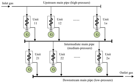
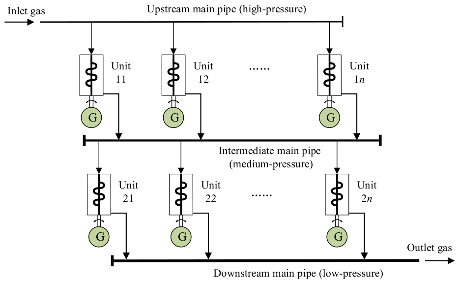
This study focused on scenarios with small and medium capacities and moderate pressure differences, such as a gas turbine, fuel cell, gas furnace, integrated energy station, their nearby upstream pipeline facilities, etc. This study adopted the concepts of modularization and combination to improve systematic flexibility and reliability. Figure 1 shows the general solution of the pressure energy power generation system proposed in this study. According to the total expansion ratio, the gas pressure could be reduced from high to low pressure directly via one-stage expansion; otherwise, it could be reduced from high to medium pressure, and then to low pressure, via multi-stage expansion. According to the gas flow rate, two or more units were employed in one stage of the expansion. At least two units should be used for both operation and standby to improve the system availability. Subsequently, based on the above systematic design and our experiences in manufacturing, the following parameters were set for one unit: a nominal diameter of ≤DN300, an inlet pressure of ≤6.3 MPa, an expansion ratio of ≤2, and an exhaust temperature of the expander (Texhaust) of ≥0 °C.
Figure 1.
General solution of differential pressure power generation system.
Hydrogen leakage is the core risk accounting for 60% of joint failures [9]. Consequently, enhancing sealing performance and mitigating leakage risks are the primary objectives of this study. Common seals include mechanical seals, hydraulic and pneumatic seals, rubber seals, labyrinth seals, and magnetic fluid seals. How to transfer the rotating shaft work from the inside of a high-pressure pipeline or container to the outside as efficiently as possible with extremely low or zero leakage is the core difficulty. Therefore, we first excluded the mechanical seal scheme due to its leakage risk, and then excluded the canned generator scheme due to its low efficiency. Then, the scheme was designed based on magnetic coupling transmission and magnetic fluid seal.
2.1.2. Technical Scheme Based on Magnetic Coupling Transmission
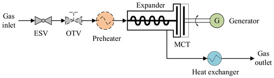
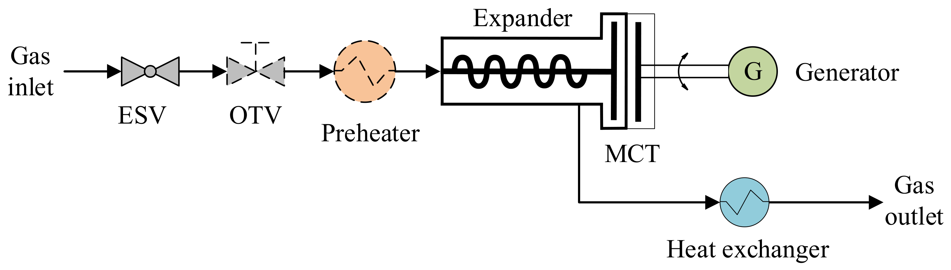
Firstly, a high-safety differential pressure power generation scheme was proposed based on magnetic coupling transmission (MCT) to achieve zero leakage. MCT involves a type of non-contact coupling, generally composed of two magnets with an isolation cover separating them. One magnet connects to the driving component, while the other connects to the motor, transmitting torque through the coupling action of the magnetic fields of the N and S poles [22]. It eliminates the need for physical connection between moving parts; therefore, it is advantageous in harsh or inaccessible environments. The scheme of one unit is shown in Figure 2. Magnetic coupling transmission is a system where a rotor with powerful permanent magnets is installed both inside and outside the container, with a pressure-bearing isolation sleeve that can effectively conduct the magnetic field. It is a static seal and ensures zero leakage, as the sealing element does not contact the drive shaft. The key hardware of the MCT scheme includes an emergency shut-off valve (ESV), an overpressure throttling valve (OTV (optional)), a preheater (optional), an expander, a magnetic coupling transmission shaft, a generator, and a heat exchanger for cold-energy utilization.
Figure 2.
Schematic diagram of differential pressure power generation scheme based on magnetic coupling transmission.
The main functions of each component are as follows: The emergency shut-off valve allows or prevents upstream fuel gas to flow toward the expander. For the scenarios with large pressure fluctuations, an overpressure throttling valve is recommended to be installed to protect downstream facilities. If the upstream pressure fluctuation is within the design range, this valve is not necessary. If the pressure drop and temperature drop across the expander are small, and the exhaust temperature is ensured to be above the dew point, the preheater is not required. Otherwise, a preheater should be installed to heat the upstream fuel gas to a certain temperature as needed based on the pressure drop and ambient temperature. Nearby waste heat, solar thermal energy, or heat supplied by a heat pump can be used as heat sources for the preheater.
The expander converts the pressure energy into mechanical energy, driving the inner rotor of a magnetic coupling transmission shaft to rotate. After pressure reduction, the fuel gas is discharged from the expander through two or more exhaust ports and then collected and transported to downstream users. Expanders can be either screw-type or turbine-type. Screw expanders are low-cost, structurally simple, stable, and reliable, and have good output characteristics. They are widely used in waste heat and pressure energy recovery. The isentropic efficiency of the expansion process is between 65% and 80% [1,23]. The target isentropic efficiency of this design is set to 70%. The screw expander is supported by maintenance-free ceramic bearings, which have the advantages of wear resistance, corrosion resistance, a low thermal expansion coefficient, excellent lubrication performance, and protection against electrolytic corrosion. The expander shell is made of hydrogen-resistant steel, and surface-coating treatment can be applied to further enhance the resistance to hydrogen embrittlement [24].
The magnetic coupling transmission shaft consists of inner and outer rotors, which are made of high-performance rare-earth permanent magnet material. The pressure-bearing isolation sleeve is installed at the end of the expander and between the inner and outer rotors. Figure 1 is a schematic diagram, not a universal structure diagram, and a coaxial arrangement is more suitable for large diameter pipelines [25]. The above arrangement is only one type of structure of a magnetic coupling transmission shaft. The arrangement of these components can also adopt the sleeve-type structure.
The isolation sleeve ensures a leak-free seal and transmits the shaft power of the inner rotor to the outer rotor. The outer rotor drives the generator to generate electricity, completing the conversion from pressure energy to electricity. According to the characteristics of gas flow variation, a gearbox can be set in front of the generator. The transmission efficiency of the shaft is key to the whole scheme, which is between 80% and 90% [26]. Considering high-pressure application scenarios and the thickness of the isolation sleeve, the target value of this efficiency is set to 85%. Furthermore, the thickness is proportional to the eddy current loss of the magnetic coupling transmission, which is then converted into heat energy. If the heat dissipation is not efficient and proper, it will heat up rapidly and cause the magnet to demagnetize irreversibly. Therefore, a heat exchanger is arranged to recover the cold energy of the exhaust gas for heat dissipation. The scheme with the leak-proof magnetic coupling transmission shaft is highly reliable; however, the overall conversion efficiency of pressure energy to electrical energy may not be satisfactory.
2.1.3. Technical Scheme Based on Dual Magnetic Fluid Seals
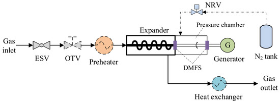
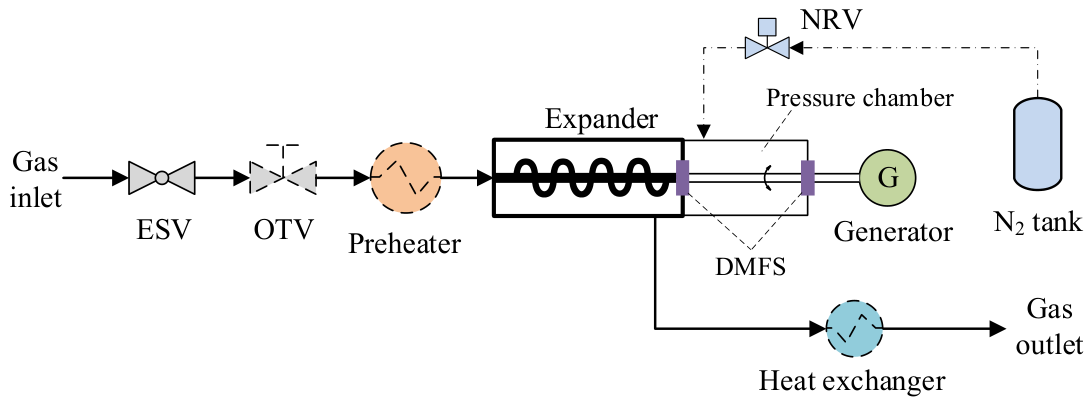
To improve energy conversion efficiency, another high-safety differential pressure power generation scheme was proposed based on dual magnetic fluid seals (DMFSs). A magnetic fluid seal is a non-contact, self-adjusting seal that uses magnetic fluids held in place with a magnetic field to create a highly reliable barrier for rotating or stationary shafts. It operates by combining magnetic fields with magnetic liquids containing micron- or nano-scale magnetic particles. When exposed to a magnetic field, the particles align along the field lines, forming a liquid O-ring that acts as a dynamic, self-repairing seal. The magnetic fluid seal technology has been widely used as it has many advantages, such as zero leakage, long service life, reliability, and stability [27]. As shown in Figure 3, the key hardware of the DMFS scheme includes an emergency shut-off valve, an overpressure throttle valve (optional), a preheater, an expander, a rotating shaft with dual magnetic fluid seals, a nitrogen pressure chamber, a generator with a gearbox, a heat exchanger (optional), a nitrogen tank, and a nitrogen-regulating valve (NRV). A nitrogen pressure detector and a hydrogen or ammonia detector are installed in the pressure chamber, alongside a matched control device.
Figure 3.
Schematic diagram of differential pressure power generation scheme based on dual magnetic fluid seals.
This DMFS scheme differs from the MCT scheme in terms of the transmission shaft, the low-pressure side of the expander, sealing, and the nitrogen subunit. The structures and functions of other components in the DMFS scheme are consistent with those in the MCT scheme. The expander and generator share the same shaft but may differ in material or surface treatment. The expander in the MCT scheme is solidly sealed at the low-pressure side end face, whereas the transmission shaft in the DMFS scheme passes through the low-pressure side end face of the expander. The core of this scheme lies in the magnetic fluid seal, which boasts low initial investment, low maintenance cost, reliable sealing, and extremely high transmission efficiency (98–99%). However, magnetic fluid seals also face some issues, such as the potential for very slight leakage. The design and test of a magnetic fluid seal for radioactive substances showed that the leakage rate was less than 10−6 mbar⋅L/s [27]. In addition, acidic gases (such as H2S) or condensate may compromise the chemical stability of the magnetic fluid. Hydrogen may dissolve in the base fluid of the magnetic fluid and permeate out. Hydrogen, being reduced, may affect the chemical stability of nanoparticles in the magnetic fluid upon prolonged exposure. Lastly, this seal is not suitable for very large pressure differentials. Therefore, to ensure sealing reliability and prevent gas leakage to the outside, a nitrogen pressure chamber is set up after the expander; the transmission shaft penetrates this chamber. A magnetic fluid seal is installed at the connection between the expander and the pressure chamber to isolate the fuel gas inside the expander from the nitrogen inside the chamber. Another magnetic fluid seal is installed at the other end of the pressure chamber to isolate the nitrogen inside it from the ambient air and maintain the pressure inside the chamber. The pressure in the chamber is always higher than the expander’s exhaust pressure via a nitrogen regulating valve, with a pressure differential margin of no less than 25%. The pressure chamber equipped with dual magnetic fluid seals serves three purposes: (a) It reduces the pressure difference before and after the magnetic fluid seal on the exhaust end of the expander, thereby protecting the sealing parts. (b) In case of seal failure or malfunction, the nitrogen flows into the expander, preventing gas leakage to the surroundings. By monitoring changes in nitrogen pressure and hydrogen concentration inside the pressure chamber, early warnings can be given in case of seal failure. (c) The design of the nitrogen injection position is optimized to cool the magnetic fluid seals. To this end, this scheme incorporates a dedicated low-power monitoring and control module.
2.2. Process Simulation
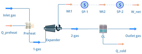
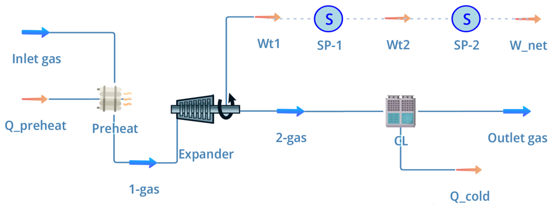
The open-source process simulator DWSIM (Version 8.6.6) was applied to model this unit and calculate the thermodynamic parameters and output power to conduct a quantitative study of the above two schemes. The DWSIM model of the MCT scheme is shown in Figure 4; that of the DMFS scheme is similar and is not presented in this paper. The Soave–Redlich–Kwong (SRK) equation of state was employed [18]. Taking the inlet temperature of 15 °C as the benchmark, when the pressure difference was 0.5 MPa, there was no need to preheat the inlet gas; when the pressure difference was 1 MPa, the inlet gas needed to be preheated to 17.7 °C to ensure that the exhaust temperature was not lower than 5 °C. “Heater” in DWSIM was employed to simulate the preheater, assuming an energy efficiency of 99% and a pressure drop of 1 kPa. Then, the preheated gas entered the screw expander to expand and generate work. “Expander” in DWSIM was used to simulate this machine with a given outlet pressure and a specific isentropic efficiency (with 70% as benchmark). The output work of the expander (Wt1) could not be completely converted into power due to the energy losses related to transmission and the generator. The transmission efficiencies ηmct and ηmfs were in the ranges of 80–90% and 98–99%, respectively. In this simulation, a “specification block” (logical block) was used to simulate the energy efficiency related to the transmission. Similarly, another “specification block” was used to simulate the generator’s mechanical efficiency. The heat exchanger that recovered the cold energy of exhaust gas was simulated by “cooler”, with an energy efficiency of 99% and a pressure drop of 1 kPa. The outlet temperature of this exchanger was the same as that of the system’s inlet gas. Details of the input data and assumptions are listed in Table A1 for the hydrogen differential pressures of 1.0 MPa as a typical case.
Figure 4.
DWSIM model based on magnetic coupling transmission scheme.
Singer et al. reported the specific expansion work (approximately 643 kJ/kg) of a single-stage expansion machine with an isentropic efficiency of 60% and a pressure difference between 35 and 15 bar [16]. The value was 639.8 kJ/kg, calculated via our simulation, and the relative difference between them was only −0.5%. The validation indicated that our simulation was rational.
2.3. Energy-Saving Evaluation
Energy efficiency is commonly defined as the ratio of useful energy output to total energy input. Based on the working principle, the useful energy of a unit consists of the net output power (Wnet) and the cold energy of the outlet gas (Qcold). The total energy input includes the energy related to differential pressure (Edp) and the energy of preheating the inlet gas (Qpreheat). Therefore, the overall energy efficiency of this unit (ηO) is calculated as follows:
where Wnet is the net output power of the unit (kW), and Edp is the pressure energy of the inlet gas (kW). In the case where preheating was required but the nearby heat source was insufficient, one solution was to supply heat using a heat pump or an electricity heater, with part of the generator’s output power being consumed to drive these devices for preheating.
When the differential pressure was small and the inlet gas temperature was relatively high, preheating was unnecessary, and Qpreheat was zero. Additionally, when waste heat was used for preheating, Qpreheat could also be neglected. When the outlet gas temperature approached the ambient temperature or when the installation site was far from cold-energy users, the generated cold energy could not be utilized. When Qpreheat and Qcold were zero or negligible and the output power was the only useful product, the energy efficiency of the unit (ηp) was defined as the ratio of the net output power to the energy related to differential pressure:
Alternatively, when Qpreheat and Qcold were negligible, the energy efficiency could be evaluated by considering the efficiencies of all conversion steps: the expander efficiency (ηexp, %), the transmission efficiencies of the MCT (ηmct) and DMFS (ηdmfs), the generator efficiency (ηgen, %), and the self-consumption rate (ηs, %). ηmct and ηmfs were defined as the ratio of the output shaft work to the input shaft work. ηs was defined as the ratio of the power consumed by the monitoring and control module and other devices to the output power of the generator. Assuming that the efficiencies of the two magnetic fluid seals were equal, the energy efficiencies of the MCT and DMFS schemes (ηp,MCT and ηp,DMFS, %) could be calculated as follows:
2.4. Economic Evaluation
Although the two schemes could safely recover the pressure energy, there were costs: the transmission energy loss of the MCT scheme was large, and the cost of the DMFS scheme using two sealing parts and equipped with a nitrogen system might be high. This study used two indicators, the levelized cost of electricity (LCOE) and the dynamic investment payback period (PBP), to evaluate the schemes’ economic performance. In this section, only the case of a differential pressure of 0.5 MPa is analyzed as a conservative condition. Considering the exhaust temperature and cooling capacity levels and possible application scenarios, the revenue related to cooling energy was not included in the following assessment. Then, the LCOE was calculated as follows:
where I0 represents the initial expenditure; Ai represents the total annual cost in year i, including the financing, utilities, repairs, maintenance, labor, and administrative costs. Eele, r, and n represent the annual amount of power generation (kWh), the discount rate (%), and the lifetime of the device (20 years), respectively. The economic model includes direct and indirect capital investments, operation and replacement costs, labor costs, etc. [28,29]. Equipment cost is an important basic parameter. The unit equipment cost of a natural gas differential pressure power generation system typically ranges from 10,000 ¥/kW to 17,800 ¥/kW [30,31]. Considering the combined cost corrections related to working pressure and materials in the market, the unit equipment costs of the MCT and DMFS schemes at a pressure difference of 0.5 MPa were estimated to be approximately 14,000 ¥/kW and 13,000 ¥/kW, respectively. The annual operation cost was estimated to be about 1% of the total capital investment [28,29]. The annual labor cost was estimated as 105 ¥. The unit equipment cost is generally a key indicator affecting the competitiveness of such technology and economy. Given the high uncertainty in these data, this paper analyzed the uncertainty of this parameter. From the perspective of operating costs, equivalent operating hours (EOHs) may vary greatly with application scenarios, which will lead to the equal sharing of fixed investment costs. When the cold energy is not considered, the electricity price is the only parameter to determine the income. Therefore, this study focused on the impact of the above parameters on economic indicators.
2.5. Avoided Carbon Emission Evaluation
Carbon emission was generally evaluated by the amount of greenhouse gas emissions. Within the unit, the fuel gas functioned solely as a mechanical energy carrier. It was neither combusted, chemically transformed, nor consumed; thus, no direct carbon emissions were attributed to the operation of the unit. From the perspective of life cycle assessment, the manufacturing, installation, and disassembly indirectly caused some carbon emissions. Giardinella and Gopalakrishnan reported a gate–gate life cycle assessment on three waste pressure recovery systems [32]. The generated electricity was assumed to displace an equivalent amount of electricity from the regional power grid, and the indirect carbon emissions related to devices or facilities were not considered. This work adopted the same assumptions and carried out a gate–gate assessment, excluding the carbon emissions related to facility manufacturing and disassembly. Note that this may underestimate the carbon emissions.
Then, the avoided carbon emissions (ACE) were the product of the power generation amount and the carbon emission factor of local electricity. This work further considered the decline in the carbon emission factor during China’s energy transition. Therefore, the life cycle avoided carbon emissions over the product’s lifetime were calculated as follows:
where fi is the carbon emission factor in year i. The time span in this study was 2026 to 2045. The carbon emission factors of each year are detailed in Table 1 [33].
Table 1.
Predicted carbon emission factors of electricity of China’s electricity grid.
3. Results and Discussion
3.1. Typical Operating Conditions
Two typical operating conditions for hydrogen pipes were taken as examples. The following parameters were the same in both operating conditions: the nominal diameter of the inlet gas pipeline was DN200; the volumetric flow rate was 2500 m3/h; the inlet temperature of the fuel gas was 15 °C (no preheating was needed); and the exhaust pressure was 3.6 MPa. The following parameters were different: the inlet pressures were 4.1 MPa and 4.6 MPa, respectively; the pressure differences (Δp) were 0.5 MPa and 1 MPa, respectively; and the expansion ratios were 1.14 and 1.28, respectively.
3.2. Energy-Saving Benefits
Table 2 shows the key results of both schemes when ηmct and ηmfs are 80% and 98%, respectively. Under the same pressure difference, the Wp and Qc of the DMFS scheme are significantly higher than those of the MCT scheme, in which the cooling energy for the isolation sleeve is deducted. This is primarily because the transmission efficiency of the DMFS scheme is much higher than that of the MCT scheme. For the same scheme, with the increase in Δp, the Wnet and Qc increase, whereas the Texhaust significantly decreases. The designer should check whether the exhaust temperature is too low under high differential pressure conditions. When Δp is 0.5 MPa, the Wnet of the MCT and DMFS schemes are 167.0 kW and 200.1 kW, respectively, which are comparable to the power output of a 2.0 L turbocharged engine in a passenger car. When Δp is 1 MPa, the Wnet of both schemes are 386.9 kW and 463.5 kW, respectively, which are sufficient to support simultaneous charging for multiple electric vehicles. Under this condition, the ηp of the MCT and DMFS schemes are 54.9% and 65.8%, respectively, indicating that both schemes offer significant energy-saving benefits, with the DMFS scheme demonstrating superior energy efficiency.
Table 2.
Key output results of the two schemes.
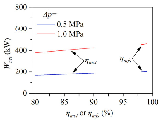
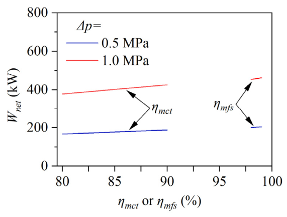
Figure 5 further illustrates the variation in net output power with transmission efficiency and differential pressure. When ηmct and ηmfs are 80% and 98%, respectively, the difference in Wnet between both schemes is 16.5%. When ηmct and ηmfs are increased to 80% and 99%, respectively, the difference in Wnet decreases to 8.0%. Meanwhile, the ηp of the MCT scheme increases from 54.9% to 61.7%, while that of the DMFS scheme increases from 65.8% to 67.1%. The MCT scheme has the advantages of sealing and maintenance, but it is more challenging to design and manufacture, with lower energy conversion efficiency. In contrast, the DMFS scheme always maintains certain advantages in energy performance.
Figure 5.
Variations in Wnet with ηmct, ηmfs, and Δp.
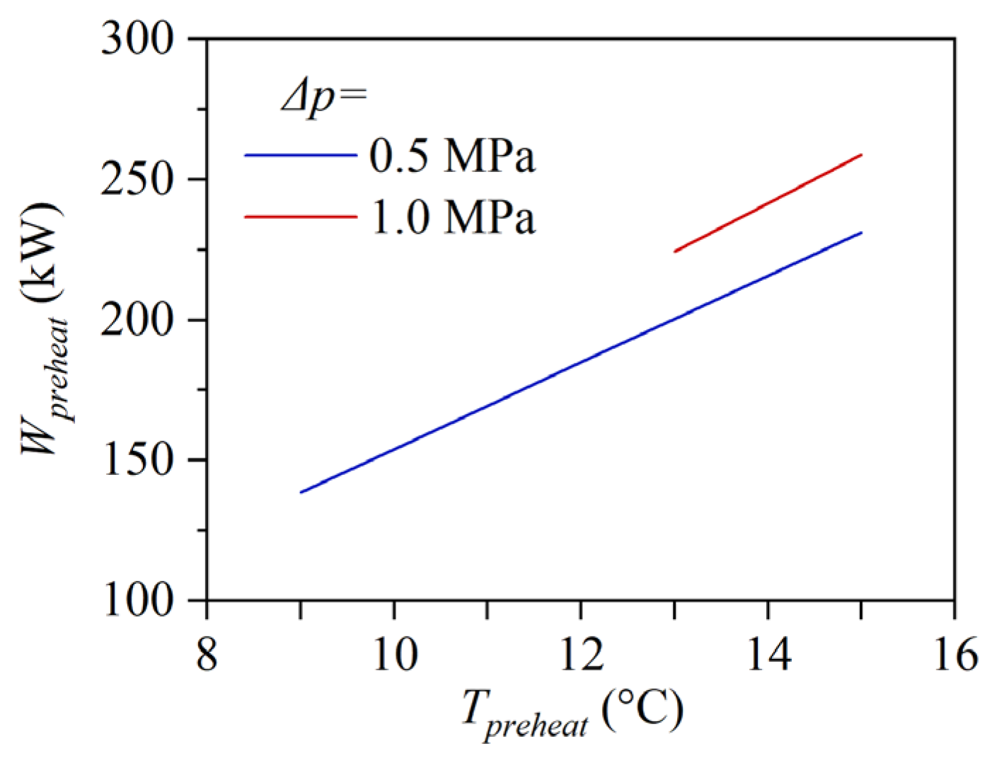
The evaluation above is based on an inlet gas temperature of 15 °C with no preheating. This section further assesses the energy conversion performance under adverse conditions. It is assumed that the inlet gas temperature is 0 °C, no waste heat is available nearby, and an air-source heat pump is used to preheat the inlet gas. The preheating temperature (Tpreheat) is set inversely to ensure that the exhaust temperature does not fall below 0 °C. The coefficient of performance of the heat pump is assumed to be 2.32 [34], and its power consumption (Wpreheat) is supplied by the generator of this unit. Figure 6 shows that in the case of Δp of 0.5 MPa, the minimum Tpreheat is 9 °C. As Tpreheat rises from 9 °C to 15 °C, Wpre increases from 138.6 kW to 231.2 kW. Compared with the Wnet in Table 1, the ηs associated with preheating reaches or exceeds 69.3%, i.e., 69.3% or greater output power is used by the heat pump. When Tpreheat exceeds 13 °C, the generator output power is less than the power consumption by the heat pump. In the case of a Δp of 1.0 MPa, the minimum Tpreheat is 13 °C, and as Tpreheat rises from 13 °C to 15 °C, Wpreheat increases from 224.4 kW to 258.9 kW. The ηs associated with preheating reaches or exceeds 49.5%. Although the generator output power remains greater than the heat pump power consumption, the self-consumption ratio remains considerably high. Clearly, the whole energy conversion performances significantly deteriorate under the preheating mode. Therefore, the minimum preheating temperature should be applied when preheating is required and no waste heat is available. Moreover, the above results also indicate that the nearby waste heat should be preferentially used for preheating rather than the power generated by this unit. Alternatively, solar thermal energy or low-carbon renewable fuels should be considered as the heat source.
Figure 6.
Relationship between Wpreheat and Tpreheat at different Δp.
3.3. Cost Performances
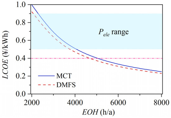
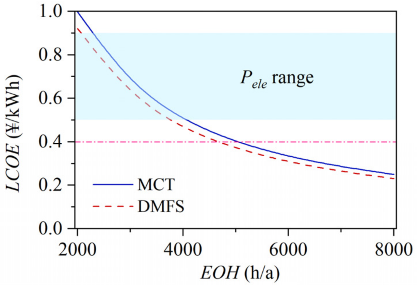
Figure 7 shows that with the increase in annual equivalent operating hours (EOHs), the levelized cost of electricity of both schemes decreases rapidly at first and then slowly. The LCOE of the MCT scheme is consistently higher than that of the DMFS scheme with the same EOH. When the EOHs of the MCT and DMFS schemes exceed 3500 h and 2800 h, respectively, their LCOE falls below the current electricity price (Pele) for industrial users in China, which generally ranges from 0.5 to 0.9 ¥/kWh. When the EOHs of the MCT and DMFS schemes exceed 5000 h and 4600 h, their LCOE falls below the feed-in tariff of coal-fired power plants in China (approximately 0.4 ¥/kWh, as shown by the dot dash line in Figure 7). The results indicate that both differential pressure power generation schemes are economically feasible under appropriate EOH conditions.
Figure 7.
Relationship between LCOE and EOH.
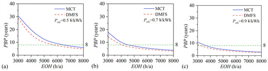
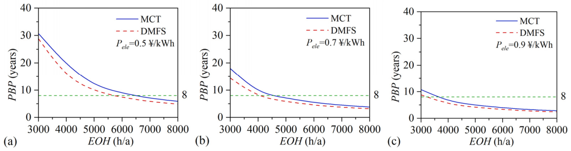
Figure 8 illustrates the relationship between the dynamic PBP and the annual EOH, where Pe denotes the selling electricity price for the differential pressure power generation unit. For a fixed Pele, PBP decreased rapidly at first and then gradually with the increase in EOH. The PBP of the DMFS scheme is always shorter than that of the MCT scheme. As Pele increases, the PBP of both schemes also significantly decreases. The green dotted line in Figure 8 represents a PBP of 8 years, which is a common target value for energy projects in China. When the Pele values are 0.5, 0.7, and 0.9 ¥/kWh, respectively, the EOHs corresponding to an 8-year PBP for the MCT scheme are approximately 6500, 4700, and 3600 h/a, respectively; for the DMFS scheme, they are approximately 5700, 4100, and 3200 h/a, respectively.
Figure 8.
Relationship between PBP and EOH at different Pele, (a) Pele of 0.5 ¥/kWh, (b) Pele of 0.7 ¥/kWh, and (c) Pele of 0.9 ¥/kWh.
Under the same conditions, the economic performance of the DMFS scheme is better than that of the MCT scheme; however, the gap between them gradually decreases with the increase in the EOH. In general, neither scheme is recommended for scenarios with an EOH below 3000 h/a. For an EOH of 6000 h/a or higher, the PBP values of the MCT and DMFS schemes do not exceed 5.5 years and 4.6 years with the baseline Pele (0.7 ¥/kWh), respectively, indicating their strong economic competitiveness, comparable to that of natural gas differential pressure power generation [4]. The above results demonstrate that both schemes can yield profits; nevertheless, the DMFS scheme exhibits better economic performance than the MCT scheme under the same conditions. Based on the technical and cost models, the EOHs for the MCT and DMFS schemes should not be less than 6500 h/a and 6000 h/a, respectively.
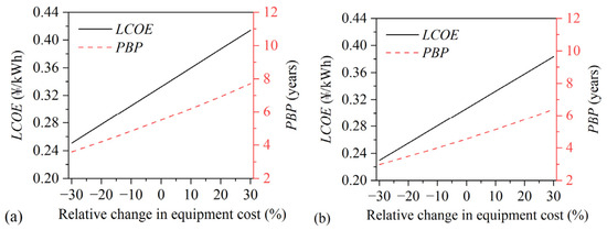
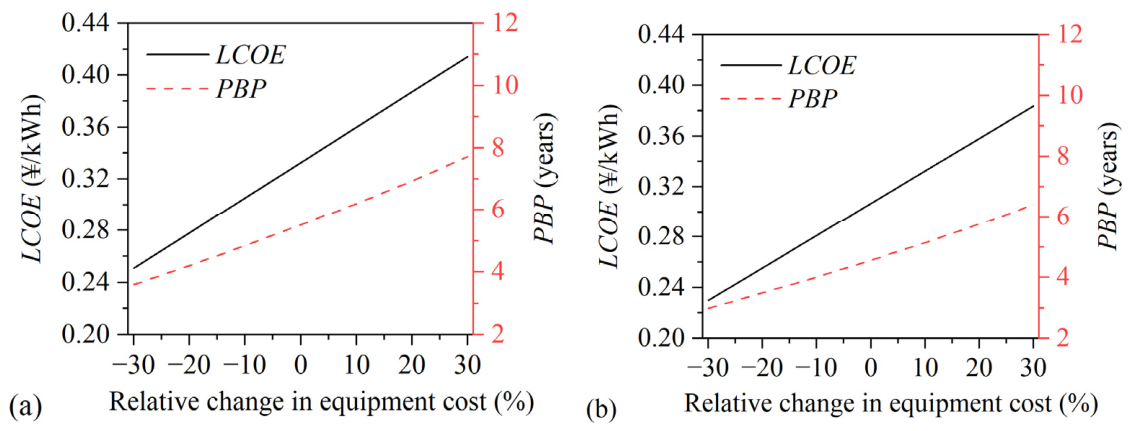
The sensitivity coefficients of LCOE to equipment cost and EOH were in the ranges of 0.82–0.84 and −0.75–1.5, respectively. The sensitivity coefficients of PBP to equipment cost, EOH, and Pele were in the ranges of 1.15–1.34, −0.93–−2.5, and −0.98–−2.23, respectively. These results indicate that equipment cost, EOH, and Pele are crucial parameters for the schemes’ economic competitiveness. As the equipment cost was estimated by referring to that of natural gas differential pressure power generation facilities, the uncertainty analysis was carried out for the equipment cost to further explore the economic feasibility of the two schemes. Figure 9 shows that under the benchmark conditions of 6000 h and 0.7 ¥/kWh, the LCOE and PBP increased almost linearly with the relative change in equipment cost. Even if the equipment cost increased by 30%, as shown by Figure 9a, the LCOE and PBP of the MCT scheme did not exceed 0.42 ¥/kWh and 7.7 years, respectively; meanwhile, as shown by Figure 9b, those of the DMFS scheme did not exceed 0.39 ¥/kwh and 6.4 years, respectively. The results indicate that the two schemes would be profitable when the equipment cost rises moderately.
Figure 9.
Variations in LCOE and PBP with relative change in equipment cost, (a) MCT scheme, and (b) DMFS scheme.
3.4. Carbon Emission Reduction Benefits
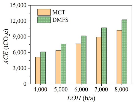
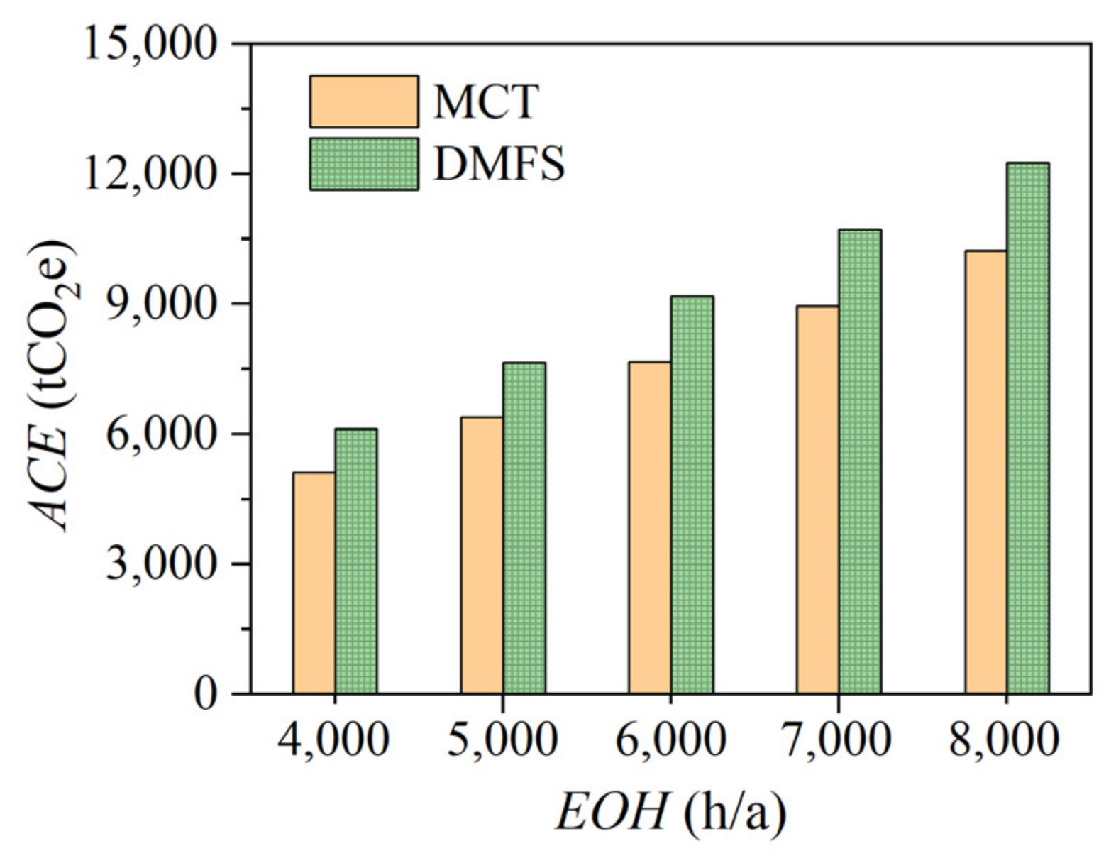
Figure 10 shows that, when the EOH increased from 4000 h to 8000 h, the ACE of the MCT scheme increased from 5112 tCO2e to 10,224 tCO2e, and that of the DMFS scheme increased from 6125 tCO2e to 12,250 tCO2e, with the difference between the two schemes gradually widening. Carbon emission reduction benefits can be measured by referring to the carbon sink capacity of forests. The average carbon sink density of forests in China is proximately 40 t/hm2 [35]. When the EOH was 4000 h, 6000 h, and 8000 h, the ACE of the MCT scheme was equivalent to the carbon sink of 128 hm2, 192 hm2, and 256 hm2 forests, respectively, and that of the DMFS scheme was equivalent to the carbon sink of 153 hm2, 230 hm2, and 306 hm2 forests, respectively. The results indicate that the differential pressure power generation with a DN200 pipe and a pressure difference of 0.5 MPa could play a significant role in reducing carbon emissions over its lifetime.
Figure 10.
Relationship between ACE and EOH.
4. Conclusions
Two zero-emission differential pressure power generation schemes, one based on magnetic coupling transmission and another based on dual magnetic fluid seals, were proposed and designed to address the challenges of pressure energy recovery from high-risk gases. Focusing on low- and medium-pressure scenarios, both schemes were analyzed based on DWSIM modeling, and compared in terms of energy efficiency, economic performance, and avoided carbon emissions. The main conclusions are summarized as follows. The two schemes were designed for scenarios with a nominal diameter of DN300 or less, an inlet pressure of up to 6.3 MPa, and an expansion ratio of up to 2. It is recommended that two or more units be used simultaneously. The MCT scheme employs a static seal, offering advantages such as no moving wear, a simple structure, and no leakage risk. However, its energy efficiency is relatively low (54.9–61.7%). The DMFS scheme utilizes dual magnetic fluid seals, providing higher transmission efficiency. Because this scheme uses a nitrogen pressure chamber along with the monitoring and control module for nitrogen pressure and hydrogen concentration, it achieves a better balance between energy efficiency (65.8–67.1%), sealing reliability, early warning capability, and maintainability. Under suitable EOH conditions, the LCOE of both schemes is lower than the feed-in tariff of coal-fired power plants in China, and the PBP is estimated to be less than 5.5 years. Both schemes positively contribute to the mitigation of carbon emissions by generating power without any indirect emission of greenhouse gases. The ACE of the MCT and DMFS schemes with EOH of 8000 h/a are equivalent to the carbon sink of 256 hm2 and 306 hm2 forests. Under the same conditions, the DMFS scheme is superior to the MCT scheme in terms of energy and economic performance, and carbon emission reduction.
With the accelerated development of green hydrogen and ammonia infrastructure, the schemes are expected to have application prospects in pipeline transportation, hydrogen-related chemical plants and steel plants, gas turbine power plants, etc. However, the results and conclusions are based on simulations and require experimental validation. Furthermore, this study has following limitations. Firstly, the efficiency of the expander is a crucial indicator of the systematic energy efficiency, which was kept constant in this study. Future efforts should focus on maximizing the efficiency of screw expanders; alternatively, high-efficiency microturbines should be considered and developed as replacements for screw expanders. Secondly, the reliability and lifetime of both schemes need strict and comprehensive testing for the targeted gas. Thirdly, the equipment cost was estimated by referring to that of natural gas facilities, as no manufacturing data are available. A more accurate cost analysis should be carried out based on actual manufacturing activities. Finally, the carbon emission assessment should be extended from the gate-to-gate method to the cradle-to-grave method. Further experimental studies and pilot tests should be carried out.
Author Contributions
Conceptualization, G.S.; Methodology, G.S., S.W. and H.Z.; Validation, H.G. and J.X.; Software, X.W. and H.G.; Formal Analysis, G.S., X.W. and H.G.; Investigation, S.W., J.X. and L.W.; Resources, C.L., S.W. and L.W.; Data Curation, X.W. and H.G.; Writing—Original Draft Preparation, G.S. and H.G.; Writing—Review and Editing, X.W., S.W., C.L. and H.Z.; Visualization, G.S., X.W. and H.G.; Supervision, C.L. and H.Z.; Project Administration, C.L. and H.Z.; Funding Acquisition, G.S. and H.G. All authors have read and agreed to the published version of the manuscript.
Funding
This research was funded by the Open Research Fund of Jiangsu Provincial Key Laboratory of Multi-energy Integration and Flexible Power Generation Technology, Nanjing Institute of Technology (No. MEIP202504); the Industry-University-Research Cooperation Project of Jiangsu Province (No. BY20241077); and the Jiangsu Provincial Department of Science and Technology of China (No. BT2024005).
Data Availability Statement
Dataset available on request from the authors.
Conflicts of Interest
Sheng Wang and Jingxin Xu were employed by the China Energy Science and Technology Research Institute Co., Ltd. Lirong Wang was employed by the Suzhou Faqizhuo Technology Co., Ltd. The remaining authors declare that the research was conducted in the absence of any commercial or financial relationships that could be construed as a potential conflict of interest.
Appendix A
Table A1.
Objects and Settings of a typical DWSIM model.
References
- Yang, Z.; Ma, J.; Yun, Q.; Liu, Y.; Zhu, Y.; He, S. Status Quo and Development Trends of Natural Gas Pressure Differential Power Generation Technology. Pet. New Energy 2025, 37, 131–136. [Google Scholar] [CrossRef]
- Chang, X.; Zhang, X.; Ma, H.; Hu, D.; Zhu, Y.; Li, W.; Chen, H. Research on Characteristics of Natural Gas Differential Pressure Power Generation System. Energy Sources Part A Recover. Util. Environ. Eff. 2025, 47, 8799–8812. [Google Scholar] [CrossRef] [Scilit]
- Kim, K.M.; Oh, M.S.; Park, S.Y. Hydroelectric Power Generation Using Differential Pressure of District Heating Pipe in a Thermal Grid. In Proceedings of the 2017 4th Asia-Pacific World Congress on Computer Science and Engineering, Nadi, Fiji, 11–13 December 2017. [Google Scholar]
- Luo, C.; Zhou, Y.; Lin, D.; Zhang, H.; Wang, M.; Ke, D. Techno-Economic Analyses of Steam Differential Pressure Power Generation in Integrated Energy System. In Proceedings of the 2020 IEEE Sustainable Power and Energy Conference, Chengdu, China, 23–25 November 2020. [Google Scholar]
- Yao, Y.; Tan, L.; Chen, F.; Pan, A.; Ma, Q.; Zhao, J.; Kang, R. Hydrogen Energy Industry in China: The Current Status, Safety Problems, and Pathways for Future Safe and Healthy Development. Saf. Sci. 2025, 186, 106808. [Google Scholar] [CrossRef] [Scilit]
- Zhang, C.; Shao, Y.; Shen, W.; Li, H.; Nan, Z.; Dong, M.; Bian, J.; Cao, X. Key Technologies of Pure Hydrogen and Hydrogen-Mixed Natural Gas Pipeline Transportation. ACS Omega 2023, 8, 19212–19222. [Google Scholar] [CrossRef] [Scilit]
- Kuchta, T.; Wróblewska, A.; Holewa-rataj, J.; Król, A. Threats and Challenges Associated with Ammonia Transport via Pipeline Systems. Appl. Sci. 2025, 15, 11465. [Google Scholar] [CrossRef] [Scilit]
- Zhang, J.; Jiang, Y.; Kong, X.; Yao, C.; Ba, Q.; Li, X. Current Status and Prospects of Hydrogen Risk Assessment Technologies. Sci. Technol. Foresight 2024, 3, 91–104. [Google Scholar] [CrossRef]
- Hong, S.; Ma, X.; Zhao, Y.; Zhang, M.; Li, C.; Luo, J.; Wang, Y.; Hong, B. Advances in Hydrogen Pipeline Joints: Materials, Sealing Structures, and Intelligent Monitoring for Safe Hydrogen Transport. Energies 2026, 19, 1408. [Google Scholar] [CrossRef] [Scilit]
- Kojima, Y. Safety of Ammonia as a Hydrogen Energy Carrier. Int. J. Hydrogen Energy 2024, 50, 732–739. [Google Scholar] [CrossRef] [Scilit]
- Yang, F.; Wang, T.; Deng, X.; Dang, J.; Huang, Z.; Hu, S.; Li, Y.; Ouyang, M. Review on Hydrogen Safety Issues: Incident Statistics, Hydrogen Diffusion, and Detonation Process. Int. J. Hydrogen Energy 2021, 46, 31467–31488. [Google Scholar] [CrossRef] [Scilit]
- Ahad, M.T.; Bhuiyan, M.M.H.; Sakib, A.N.; Corral, A.B.; Siddique, Z. An Overview of Challenges for the Future of Hydrogen. Materials 2023, 16, 6680. [Google Scholar] [CrossRef] [Scilit] [PubMed]
- Zou, A.; Zeng, Y.; Luo, E. New Generation Hydrogen Liquefaction Technology by Transonic Two-Phase Expander. Energy 2023, 272, 127150. [Google Scholar] [CrossRef] [Scilit]
- Chen, Y.; Li, H.; Che, X.; Ren, G.; Zhang, Z. A Parallel-Expander Configuration for High-Efficiency Hydrogen Refueling Station. Int. J. Hydrogen Energy 2026, 209, 153591. [Google Scholar] [CrossRef] [Scilit]
- Soujoudi, R.; Manteufel, R. Thermodynamic, Economic and Environmental Analyses of Ammonia-Based Mixed Refrigerant for Liquefied Natural Gas Pre-Cooling Cycle. Processes 2021, 9, 1298. [Google Scholar] [CrossRef] [Scilit]
- Singer, G.; Köll, R.; Aichhorn, L.; Pertl, P.; Trattner, A. Utilizing Hydrogen Pressure Energy by Expansion Machines—PEM Fuel Cells in Mobile and Other Potential Applications. Appl. Energy 2023, 343, 121056. [Google Scholar] [CrossRef] [Scilit]
- Rufer, A. Expansion Work Recovery of Hydrogen for a FC-Truck-Tentative Design of an Expansion Machine. Inventions 2023, 8, 89. [Google Scholar] [CrossRef] [Scilit]
- Zhan, N.; Pang, Z.; Shang, P.; Lao, J.; Yang, J. Analysis of the Selection of Gas Pressure Difference Power Generation Technology for Offshore Gas Fields. Energy Convers. 2026, 45, 153–157. [Google Scholar] [CrossRef]
- Krivshich, N.G.; Pavlyuk, S.A.; Deineka, A.V.; Kolesnik, S.A. Introduction and Use of Dry Gas Seal Systems on Ammonia Plant Compressors. Chem. Pet. Eng. 2003, 39, 32–34. [Google Scholar] [CrossRef] [Scilit]
- Gao, N.; Li, J.; Zhang, J.; Sun, F.; Xiao, F. Application Prospect of Differential Pressure Power Generation Technology in Long-Distance Natural Gas Pipeline. Energy Conserv. Meas. Pet. Petrochem. Ind. 2025, 15, 7–11. [Google Scholar]
- JB/T 11289-2012; Dry Gas Seal Technical Conditions. Ministry of Industry and Information Technology of China: Beijing, China, 2012. Available online: https://www.renrendoc.com/p-984925.html (accessed on 15 April 2026).
- Yan, G.; Zhao, Z.; Wang, L.; Zhang, Q.; Gao, W. Research and Test of Gas Well Differential Pressure Generator. Energy Conserv. Technol. 2019, 37, 413–415. [Google Scholar]
- Li, G.; Wu, Y.; Zhang, Y.; Zhi, R.; Wang, J.; Ma, C. Performance Study on a Single-Screw Expander for a Small-Scale Pressure Recovery System. Energies 2017, 10, 6. [Google Scholar] [CrossRef] [Scilit]
- Wetegrove, M.; Duarte, M.J.; Taube, K.; Rohloff, M.; Gopalan, H.; Scheu, C.; Dehm, G.; Kruth, A. Preventing Hydrogen Embrittlement: The Role of Barrier Coatings for the Hydrogen Economy. Hydrogen 2023, 4, 307–322. [Google Scholar] [CrossRef] [Scilit]
- Ruiz-Ponce, G.; Arjona, M.A.; Hernandez, C.; Escarela-Perez, R. A Review of Magnetic Gear Technologies Used in Mechanical Power Transmission. Energies 2023, 16, 1721. [Google Scholar] [CrossRef] [Scilit]
- CHen, N.; Dong, Y.; Xia, Q.; Wu, X. Research on Transmission Efficiency of Magnetic Actuator. Chem. Eng. Equip. 2024, 3, 67–68+72. [Google Scholar] [CrossRef]
- Liu, L.; Li, D.; Li, L.; Wei, Y.; Li, Q.; Qi, Z. Tribology International Design and Study of Sealing Performance for Ultra-Clean and Highly Reliable Magnetic Fluid Seals. Tribol. Int. 2026, 213, 111091. [Google Scholar] [CrossRef] [Scilit]
- Chen, J.; Song, G.; Li, J.; Sheng, Z. Techno-Economic and Carbon Footprint Assessments of a 2 KW Zero Boil-off System for Large-Scale Commercial Liquid Hydrogen Storage. Int. J. Hydrogen Energy 2026, 204, 153262. [Google Scholar] [CrossRef] [Scilit]
- Kumar, P.; Date, A.; Shabani, B. Techno-Economic Analysis of an Integrated Desalination-Renewable-Hydrogen System for Zero-Emission Freshwater and Electricity Production. Energy Convers. Manag. 2026, 353, 121231. [Google Scholar] [CrossRef] [Scilit]
- Wei, Y.; Yang, L.; Zou, X.; Xiong, W. Research on Pressure Energy Generation Technology of Roots Power Machine in Town Gas Gate Station. Gas Technol. 2025, 9, 24–27. [Google Scholar] [CrossRef]
- Wang, T. Simulation and Comprehensive Evaluation of Natural Gas Differential Pressure Power Generation Process. Master’s Thesis, Northeast Petroleum University, Daqing, China, 2024. [Google Scholar]
- Giardinella, S.; Gopalakrishnan, V. Waste Pressure Energy Recovery System, Life Cycle Analysis (LCA) Report, General Technology; Illinois Sustainable Technology Center: Champaign, IL, USA, 2025. [Google Scholar]
- Tian, P.; Liang, X.; Guan, Y.; Zhao, Y.; Mao, B.; Xue, T. Whole Life Cycle Carbon Emission and Power Generation Structure Transformation Pathway Planning of China’s Power. Clim. Change Res. 2024, 20, 97–106. [Google Scholar] [CrossRef]
- Wu, C.; Liu, F.; Li, X.; Wang, Z.; Xu, Z.; Zhao, W.; Yang, Y.; Wu, P.; Xu, C.; Wang, Y. Low-Temperature Air Source Heat Pump System for Heating in Severely Cold Area: Long-Term Applicability Evaluation. Build. Environ. 2022, 208, 108594. [Google Scholar] [CrossRef] [Scilit]
- Zhang, Y.; Li, X.; Wen, Y. Forest Carbon Sequestration Potential in China under the Background of Carbon Emission Peak and Carbon Neutralization. J. Beijing For. Univ. 2022, 44, 38–47. [Google Scholar] [CrossRef]


Disclaimer/Publisher’s Note: The statements, opinions and data contained in all publications are solely those of the individual author(s) and contributor(s) and not of MDPI and/or the editor(s). MDPI and/or the editor(s) disclaim responsibility for any injury to people or property resulting from any ideas, methods, instructions or products referred to in the content. |
© 2026 by the authors. Licensee MDPI, Basel, Switzerland. This article is an open access article distributed under the terms and conditions of the Creative Commons Attribution (CC BY) license.