


Abstract
A large-section tunnel has a large excavation span and high construction difficulty and is prone to roof fall and collapse and other engineering disasters under complex geological conditions. Due to the influence of the size effect, it is difficult for surrounding rock to form an arch and form an effective load-bearing structure. A timely and proactive anchoring support system is required to fully utilize the self-bearing capacity of the surrounding rock. Therefore, this paper studies a case of high-prestressed active support based on a large cross-section tunnel in eastern China, clarifying that high-prestressed active support can effectively control rock stress, plastic zone distribution, and surrounding rock deformation. Based on a prestress conversion test, the support structure and application method that meet the high-prestress application requirements of the tunnel engineering site are clearly defined. An active support field test was carried out, and the influence of prestress on the supporting structure stress and the surrounding rock deformation was analyzed. The results show that compared with a no-prestress support scheme, active support with 100 kN high prestress increased the utilization rate of anchor rod strength by 35.29%, reduced the external load on the arch by 40.9%, and reduced the settlement of the arch crown by 34.9%. This indicates that high-prestressed active support can improve the self-bearing capacity and control effect of the surrounding rock.
1. Introduction
With the continuous development of transportation infrastructure in terms of speed and scale, the construction of large-section tunnels with dual six-lane and eight-lane configurations for railways and highways has become essential [1,2,3,4,5]. Compared to regular highway tunnels, large-section tunnels exhibit significant differences in cross-sectional form, excavation span, and construction methods, leading to more complex loading conditions on their support structures [6,7]. As the dimensions of tunnel sections increase, the process of stress variation in surrounding rock becomes increasingly complex, and controlling rock deformation becomes more challenging. Consequently, the likelihood of engineering disasters, such as surrounding rock deformation and failure, during the construction of large-section tunnels significantly increases [8,9]. It is evident that the stable and rational loading of tunnel support systems is a crucial prerequisite for ensuring the safe construction of large-section tunnels [10].
Currently, numerous experts and scholars have conducted extensive research on support systems for large-section tunnels. Sun et al. [11] studied the mechanical responses of tunnels reinforced by a combined bolt–cable system. An analytical model of the convergence-confinement type is proposed that accounts for the sequential installation of finite-length fully grouted bolts and cables, as well as the effects of intermediate principal stress. Lu et al. [12] adopted laboratory and numerical methods to investigate the bearing mechanism and failure behavior of an arch joint, arch frame and arch shotcrete composite lining. On this basis, a modified safety evaluation method of arches is proposed based on the convergence-confinement method. Li et al. [13] carried out large-scale geomechanical model tests and numerical simulations with the background of the China Leguan Tunnel. The results reveal the failure behavior of the lining structure of a super-large cross-section tunnel and demonstrate stress variation in the surrounding rock under overload conditions. Li et al. [14] carried out a numerical simulation experiment and a simulation model experiment, studied the mechanical behavior of surrounding rock under prestressed bolt support, established a mechanical model of the prestressed bolt support, and determined that the main controlling factors of the support effect are prestress, anchor cable length, and anchor cable spacing. In these research studies, initial support of surrounding rock was mainly achieved using methods such as grouting bolts, reinforced mesh, and steel arches. After tunnel excavation and unloading, the support structures relied on the deformation of the rock mass itself to generate resistance forces, falling into the category of delayed passive support [15]. It is challenging to reasonably distribute the rock mass load among different support structures using this form of support.
Prestressed active support is a novel support technology developed in recent years. The basic principle involves fully utilizing the self-bearing capacity of surrounding rock to improve the stress environment of the rock mass. After rock mass excavation, prestress and anchor support are actively carried out before significant deformation and damage occur in surrounding rock. This anchoring extends into deep rock layers, transferring the peak stress of surrounding rock to deeper layers, thus avoiding excessive deformation or collapse of surrounding rock [16,17,18]. By applying high prestress, the occurrence of delamination, sliding, and cracks in surrounding rock is restricted, and the stress state of the surrounding rock is altered to increase its strength. Currently, prestressed active support is mainly applied in the support of deep underground spaces, such as coal mine tunnels [19,20]. The prestress in bolts mainly relies on torque application, with low prestress conversion efficiency. Additionally, the concentration of forces on the tail bolt during loading affects the self-bearing performance of bolts [21,22,23].
To clarify the high-prestressed active support effect on large-section tunnels and maximize the active support role of bolts, numerical experimental research under different prestress conditions for large-section tunnels is conducted in this paper. The influence of prestressing on the stress, plastic zone distribution, and deformation of surrounding rock is analyzed. The reasonable prestressing range that meets the active support requirements of large-section tunnel surrounding rock is determined. The conversion efficiency of prestress under different prestressing application methods is studied. The supporting structure and application method that meet the high-prestress application requirements of tunnel engineering sites are clarified. Based on this, an on-site test was conducted on high-prestressed active support, and the influence of prestress on the stress and surrounding rock deformation of the support structure was obtained. The effect of high-prestressed active support on large-section tunnels is clarified, providing an on-site basis for the design and construction parameter optimization of large-section tunnel support.
2. High-Prestressed Active Support Effectiveness Analysis
To clarify the effectiveness of high-prestressed active support in controlling tunnel surrounding rock, a numerical simulation experiment under different prestressed support conditions was conducted, the influence of prestress on the stress field and plastic zone of surrounding rock was studied, and the control effect of high-prestressed active support on surrounding rock was clarified.
2.1. Active Support Simulation Scheme
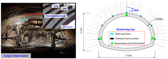
A large-section tunnel in eastern China was taken as the engineering background, and the maximum burial depth of the tunnel is 135.0 m. The cross-sectional dimensions of the tunnel are 17.8 m in width and 12.1 m in height, belonging to a large cross-section highway tunnel. The surrounding rocks of the tunnel are mainly shale, limestone, diorite, etc., with IV- and V-grade surrounding rocks being the main ones. A combined support system of “anchor net spray + arch” was adopted, and the bolt size was Φ 22 × 4000 mm, with a spacing of 600 × 750 mm between rows. The arch was made of 22b steel, with a longitudinal spacing of 60 cm. C25 concrete was sprayed for 28 cm, using Φ 8 mm steel mesh, with a specification of 20 × 20 cm.
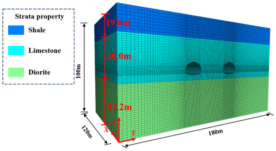
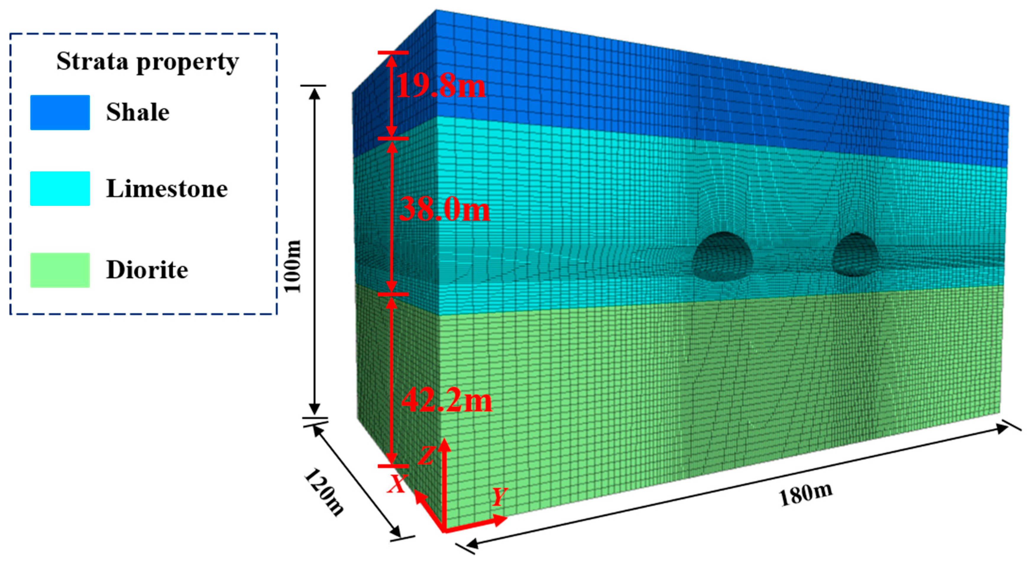
Based on the above on-site engineering conditions, the FLAC3D5.0 numerical software was used for simulation, with a model size of 120 m × 180 m × 100 m (X × Y × Z) and a 0.4 m × 0.4 m × 0.4 m regular cubic grid. A single anchor bolt can span 10 surrounding-rock grid units along its length direction. This grid scale can better reflect the restraining effect of anchor bolts on the stress, deformation, and failure development of surrounding rock under different prestressing conditions, which is conducive to accurately evaluating the reinforcement and support effect of prestressed anchor bolts on surrounding rock. The bottom boundary of the model body was fixed vertically, and the left and right boundaries were fixed horizontally. The Mohr–Coulomb constitutive model was used for the surrounding rock, the cable element was used to simulate the bolt, the beam structural element was used to simulate the arch, and the liner structural element was used to simulate the concrete spray layer. The tunnel model was excavated using the three-step method, with an upper-step excavation height of 3.5 m, a middle-step excavation height of 4.6 m, and a lower-step excavation height of 4.0 m. The excavation footage was 3.0 m. The physical and mechanical parameters of each rock layer are shown in Table 1. The contact parameters between the anchor bolt and the surrounding rock are shown in Table 2. The numerical simulation model is shown in Figure 1.
Table 1.
Physical mechanical parameters of rock strata.
Table 2.
Contact parameters between bolt and surrounding rock.
Figure 1.
Numerical simulation model of active support.
In order to clarify the control effect of different prestress on tunnel surrounding rock, the numerical simulation of tunnel surrounding rock under different bolt prestress support conditions was carried out. Among them, 0 kN, 25 kN, 50 kN, 75 kN, and 100 kN prestress are respectively applied to the anchor bolt, and the corresponding numbers are A1–A5. Other conditions, such as surrounding rock parameters, excavation method, anchor bolt parameters, and contact parameters, between the anchor bolt and surrounding rock remained unchanged. The specific scheme is shown in Table 3. The prestress application function of the cable structural unit was adopted. After the bolt unit was generated, the prestress command of the structural unit was called to apply the designed prestress to the target bolt component.
Table 3.
Comparison scheme of different prestress forces.
2.2. Analysis of Active Support Effectiveness
Excavation of a tunnel disrupts the initial stress equilibrium of the strata. According to elasticity theory, the tangential stress in the chamber sharply increases after excavation, while the radial stress dramatically decreases to zero. The surrounding rock, originally in a three-dimensional stress state, transforms into a two-dimensional stress state, leading to rock degradation and a gradual reduction in the physical–mechanical parameters of the rock mass, resulting in increased deformation. To mitigate the degradation of the rock mass caused by the release of radial stress after excavation, it is necessary to actively apply stress to the surrounding rock promptly, allowing the superficial rock to return from a two-dimensional stress state to a three-dimensional stress state. By supporting the surrounding rock, the physical–mechanical characteristics of the rock mass within the anchored zone are enhanced, maximizing the inherent load-bearing capacity of the surrounding rock.
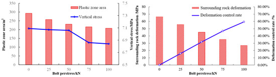
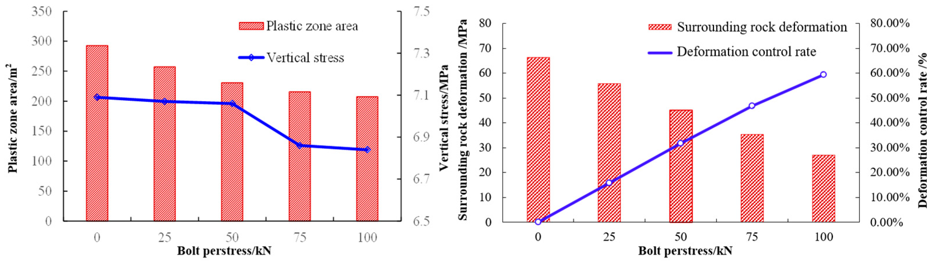
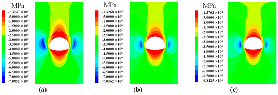
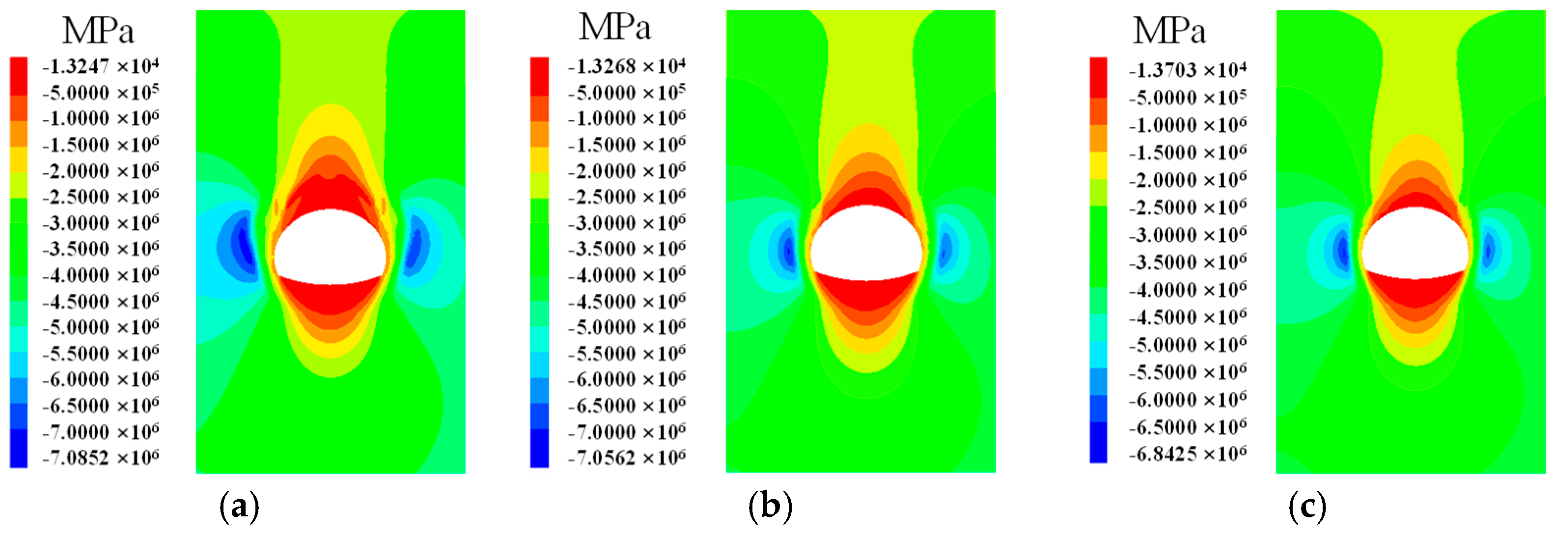
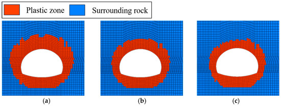
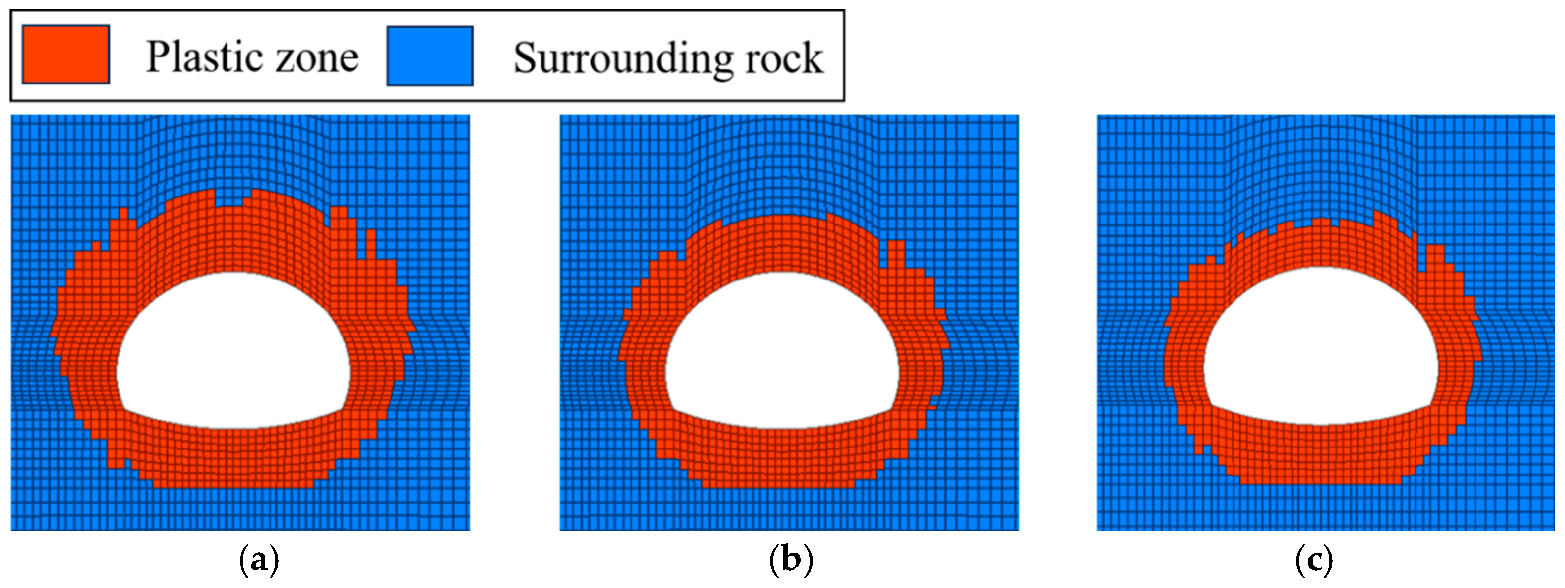
To study the influence of bolt prestress on tunnel surrounding rock, the stress, plastic zone distribution, and deformation changes of surrounding rock under different bolt prestress conditions were analyzed, as shown in Figure 2. The distribution of surrounding rock stress and plastic zones under typical conditions is illustrated in Figure 3 and Figure 4.
Figure 2.
Vertical stress, plastic zone area, and deformation changes of surrounding rock under different anchor prestressing conditions.
Figure 3.
z-direction stress nephogram under different degrees of prestressed support. (a) No prestress. (b) Prestress of 50 kN. (c) Prestress of 100 kN.
Figure 4.
Nephogram of plastic zone under different degrees of prestressed support. (a) No prestress. (b) Prestress of 50 kN. (c) Prestress of 100 kN.
From Figure 2, Figure 3 and Figure 4, it can be observed that under prestress conditions of 0 kN, 25 kN, 50 kN, 75 kN, and 100 kN, the maximum vertical compressive stress in the surrounding rock is 7.09 MPa, 7.07 MPa, 7.06 MPa, 6.86 MPa, and 6.84 MPa, respectively. With an increase in bolt prestress, both the maximum vertical compressive stress in the surrounding rock and the stress release zone gradually decrease. The plastic zone areas of the surrounding rock are 292.5 m2, 257.2 m2, 230.6 m2, 215.6 m2, and 207.4 m2, respectively, and the plastic zone area of the surrounding rock gradually decreases. The settlement of the arch crown decreased from 66.24 mm to 26.94 mm. The deformation control rates of the roof surrounding rock are 15.79%, 31.84%, 46.75%, and 59.33%, respectively. The above analysis indicates that increasing the prestress of bolts can significantly reduce roof settlement and enhance the control effect of surrounding-rock roof deformation.
In summary, high-prestressed bolt support can significantly improve the stress state of the surrounding rock, suppress the expansion of the plastic zone, improve the control effect of the deformation of the surrounding rock roof, and highlight the necessity of active support. In traditional tunnel rock support where no prestress is applied to the bolt, the self-bearing capacity of the surrounding rock cannot be fully utilized. The high-prestressed active support can actively compensate for the unloading effect of the surrounding rock during excavation, keeping the surrounding rock in a three-dimensional stress state, thereby enhancing the self-bearing capacity and control effectiveness of the surrounding rock.
3. Prestress Conversion Test
The prestress force of prestress bolts directly affects the control effect of surrounding rock. Currently, there are mainly two methods for applying prestress to bolts: the torque method and the tension method. The torque method involves applying torque to the thread at the end of the bolt during installation, generating axial tension in the bolt. The tension method involves post-anchoring the bolt and using a tensioning device to axially stretch the bolt body, thereby applying prestress. To study the efficiency of prestress transformation and the impact of prestress methods on the self-bearing performance of bolts, prestress conversion tests and structural tensile tests on bolts were conducted.
3.1. Torque–Prestress Conversion Test
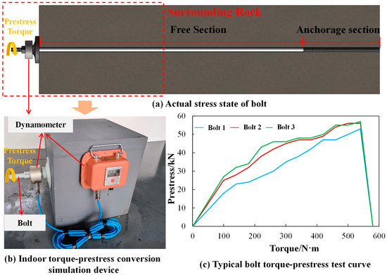
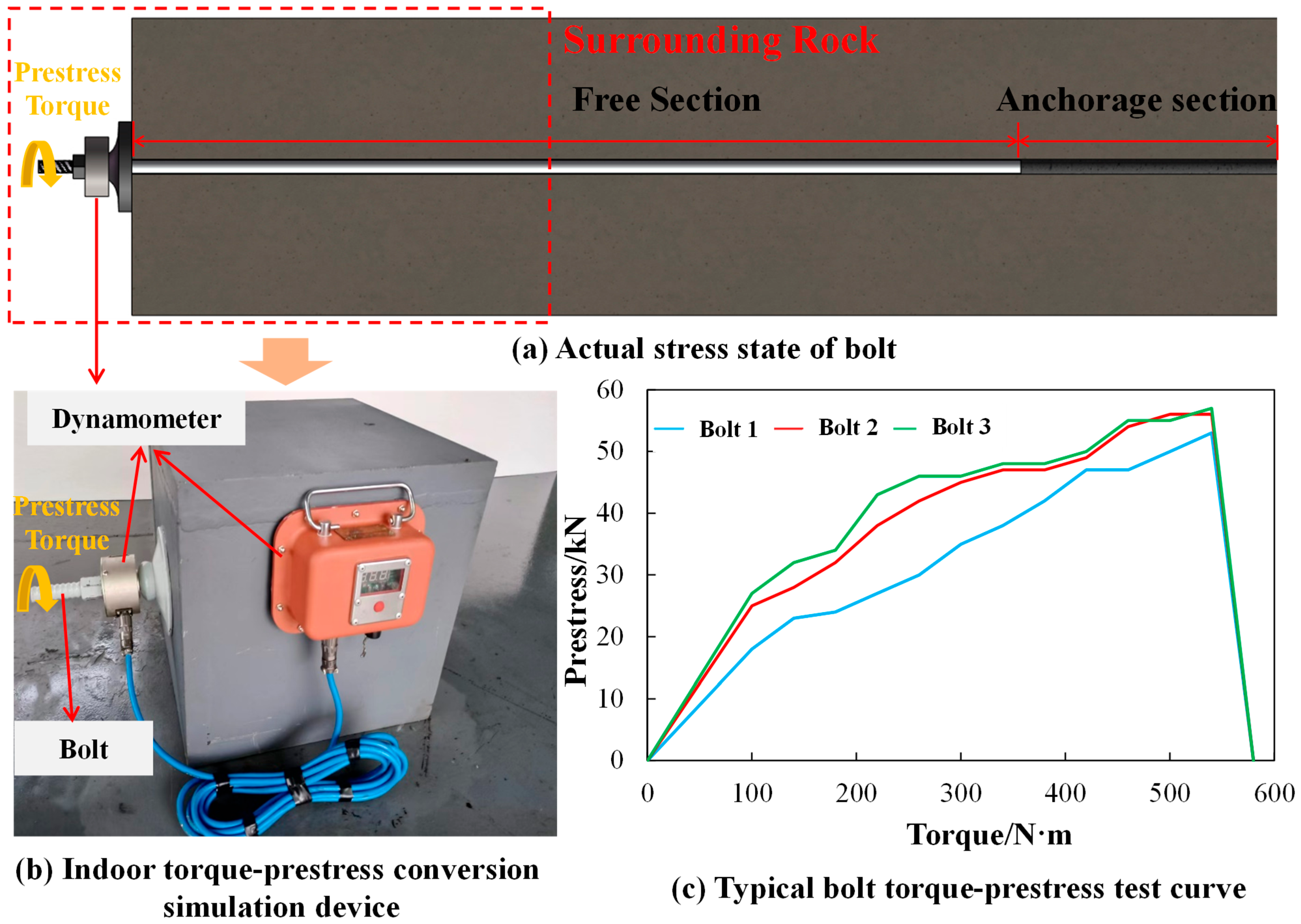
To study the efficiency of the torque method in prestress conversion, samples of HRB400 bolts with a diameter of 22 mm were taken at a tunnel engineering site, and a torque–prestress conversion test was conducted on the bolt. The test equipment included a bolt dynamometer and a support simulation device, as shown in Figure 5b. The bolt dynamometer is produced by Zhongtian Security Control Co., Ltd. Attached to Shandong University of Science and Technology in Taian, China. For each bolt, a prestress torque of 0 N·m to 580 N·m was applied, and the prestress force values were monitored and recorded, as shown in Table 4.
Figure 5.
Test equipment and results of torque–prestress conversion. (a) Actual stress state of bolt on site. (b) Indoor torque-prestress conversion simulation device. (c) Typical bolt torque-prestress test curve.
Table 4.
Summary of conversion results of torque–prestress.
From Figure 5c, it can be observed that the prestress and torque exhibit a linear relationship, and the torque–prestress conversion efficiency is generally consistent for the three bolts. When the torque reaches 540 N·m, the maximum prestress for bolt 2 and bolt 3 is 56 kN and 57 kN, respectively. When the prestress torque reaches around 580 N·m, the threads of the bolt fail, leading to a sudden drop in prestress. When the torque is 540 N·m, the average prestress of the three bolts is 55.33 kN, the standard deviation is 2.08 kN, and the coefficient of variation is 3.76%, indicating good consistency in the prestress conversion results. The average conversion ratio between prestress torque and prestress is 10.6 N·m/kN. The prestress that the bolt can apply is within 60 kN, indicating that the torque method may struggle to meet the requirements for high-prestress application.
3.2. Tensile Test of Bolt–Nut Combination Structure
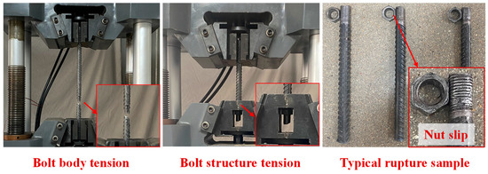
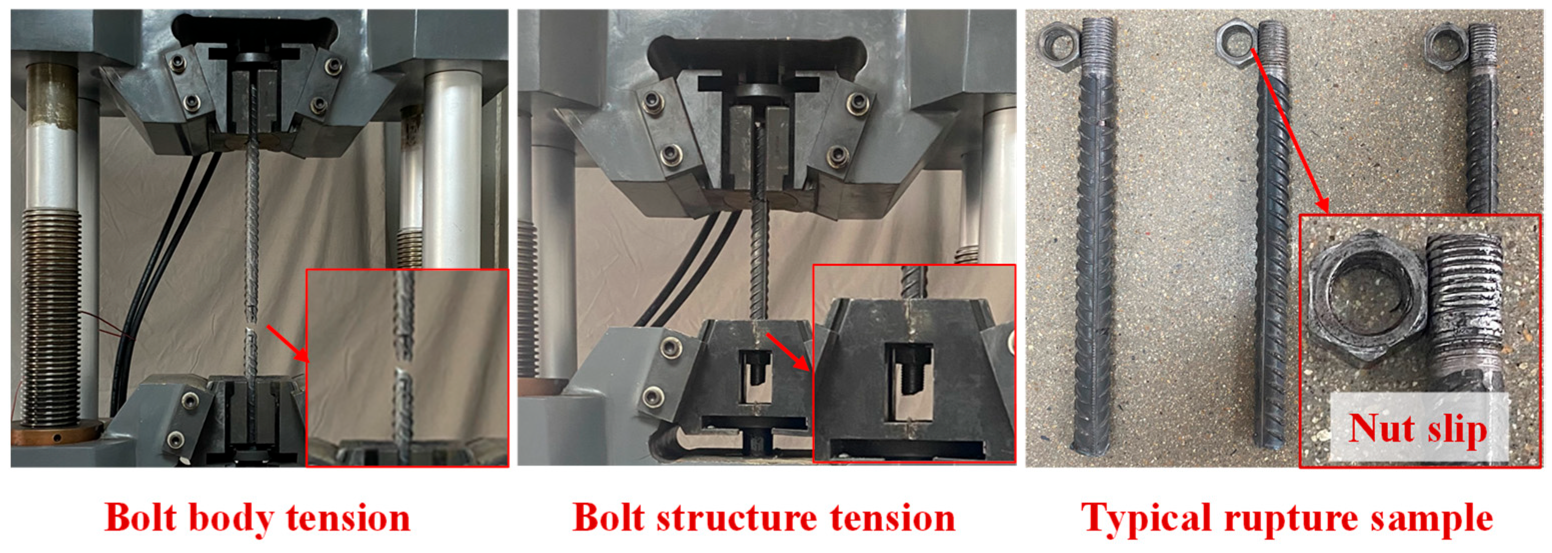
To investigate the self-bearing performance of the bolt–nut combination structure and analyze the impact of the nut on the deterioration properties of the bolt structure, a comparative test between the bolt–nut combination structure and the bolt of material static tensile test was conducted. The test equipment is a 1000 kN universal hydraulic testing machine, which is produced by Jinan Qulai Electromechanical Technology Co., Ltd. in Jinan, China. The test subjects were on-site HRB400 bolts with a diameter of Φ 22 and a length of 500 mm. Three sets of bolt–nut combination structures were selected for the test, and static tensile tests of the bolt body were conducted for comparison, as shown in Figure 6.
Figure 6.
Tensile test diagram of bolt–nut combination structure.
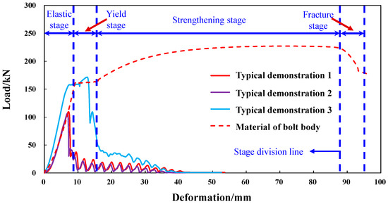
As shown in Figure 7, it can be observed that the tensile curve of the bolt body is roughly divided into four stages: an elastic stage, a yield stage, a strengthening stage, and a fracture stage. The yield load and ultimate bearing capacity of the bolt are 161.8 kN and 228.9 kN, respectively. The tensile test of the bolt–nut combination structure revealed that the instantaneous failure of the structure was caused by the nut slipping, and the bolt did not enter the strengthening stage. The average ultimate bearing capacity of the bolt body threads is 129.3 kN, which is a 43.5% reduction compared to the ultimate bearing capacity of the bolt. The bolt thread was the weak part of the whole bolt, which limited the bearing performance of the bolt. The tensile test curves of the bolt body and the bolt–nut combination structures are shown in Figure 7, where typical demonstrations 1-3 represent the typical bolt–nut combination structures in Figure 6.
Figure 7.
Tensile test curve of bolt–nut composite structure.
3.3. Tension–Prestress Conversion Test
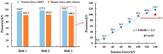
To study the supporting components and prestressing application methods that can meet the high-prestress requirements of bolts, on-site prestressing tension conversion tests of tunnels were conducted. Tensioning equipment was used to apply prestress to bolts, install load cells to measure the actual axial force of bolts, and record the tensioning force applied by the equipment during the prestress application process. The tension force of the bolt was designed to be 0 kN~140 kN, and the prestress conversion curve of the bolt is shown in Figure 8. The above anchor bolt tensioning equipment is manufactured by Weishan Longgong Machinery Co., Ltd. in Jining, China.
Figure 8.
Conversion curve of tension–prestress.
As shown in Figure 8, the actual axial forces for the three bolts when tensioned to 140 kN are 114.9 kN, 117.2 kN, and 116.7 kN, respectively, can be observed. The average value is 116.27 kN, the standard deviation is 1.21 kN, and the coefficient of variation is 1.04%. After tensioning and unloading, the bolt will experience a loss of prestress, resulting in actual prestress values of 101.9 kN, 103.5 kN, and 100.5 kN, with prestress loss rates of 11.3%, 11.7%, and 13.9%, respectively. The average value is 101.97 kN, the standard deviation is 1.50 kN, and the coefficient of variation is 1.47%. The average prestress loss rate is 12.30%, with a standard deviation of 1.40%. A linear fitting analysis was conducted on the relationship between tension force and prestress conversion during the tensioning process, with a coefficient of determination, R2, of 0.99, indicating a linear correlation between bolt tension force and prestress as a whole. When the applied tensioning force is less than or equal to 100 kN, the tensioning force transforms into prestress, with an average loss of 3.82 kN each time. When the applied tensioning force exceeds 100 kN, the efficiency of the tensioning force-to-prestress transformation decreases, resulting in an average loss of 19.13 kN each time.
3.4. Tensile Test of Bolt–Wedge Anchorage Combination Structure
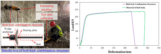
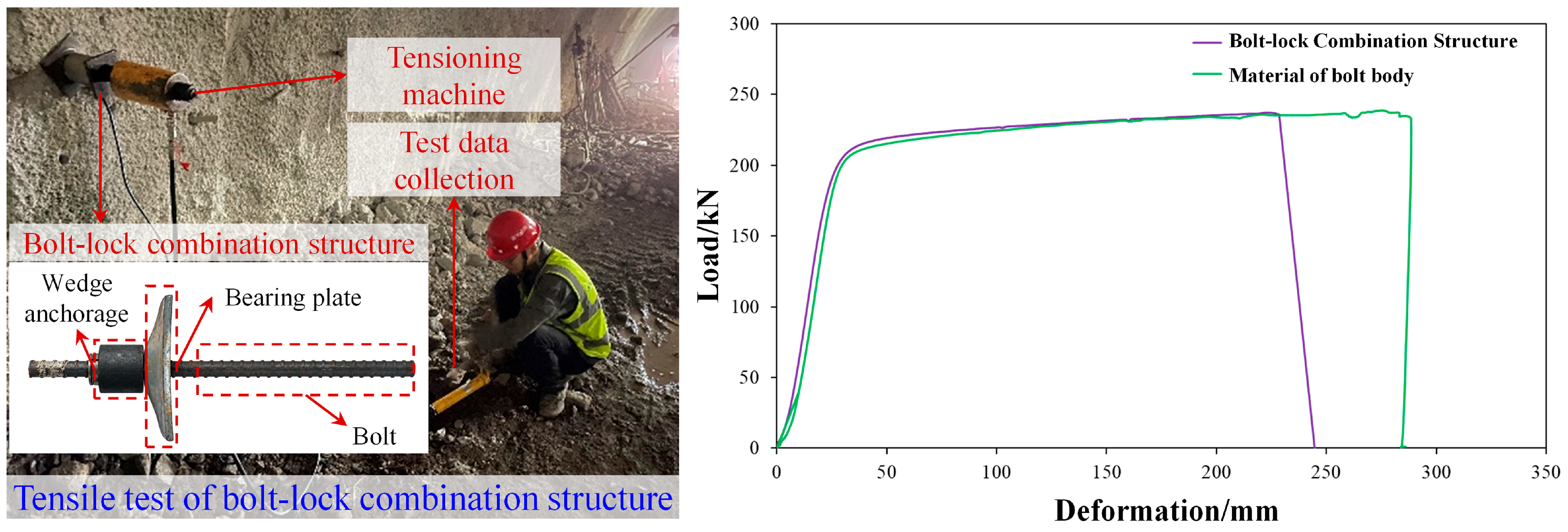
From the above-mentioned tensile test on the bolt–nut combination structure, it is evident that in the process of applying torque to a regular bolt, the threads are prone to failure, leading to nut slippage, and the full performance of the bolt body cannot be fully realized. To meet the demand for high prestress in on-site engineering, a combination structure of bolt and wedge anchorage was adopted. Unlike the bolt–nut combination structure, the bolt–wedge anchorage combination structure consists of a bolt body and a wedge anchorage installed at the end of the bolt. The wedge anchorage directly clamps and locks the bolt body, transferring external loads to the bolt. This structure is anchored by the clamping effect of the wedge anchorage on the bolt body, which can avoid nut slippage caused by thread failure. To analyze the impact of the wedge anchorage device on the deterioration properties of the bolt structure, it was necessary to conduct a static tensile test comparing the bolt–wedge anchorage combination structure with the tensile test of the bolt material. This aimed to verify whether the tensioning method meets the requirements for applying high prestress. The test process and results are shown in Figure 9.
Figure 9.
Tensile test curve of bolt–lock combination structure and bolt body.
According to the results recorded by the test equipment during the test, the ultimate tensile bearing capacities of the bolt-wedge anchorage combination structure and the bolt are 225.8 kN and 229.3 kN, respectively. The addition of the locking device had a minimal impact on the load-bearing capacity of the bolt body, with a difference rate of 1.5%. The maximum deformations for the two are 223.8 mm and 282.1 mm, respectively. The deformation of the bolt–wedge anchorage combination structure is reduced by 20.7% compared to the bolt body alone. It can be seen that applying prestress through a locking device is a more reasonable approach, as the locking device has a minimal impact on the overall load-bearing capacity of the bolt. This method can fully utilize the load-bearing performance of the bolt, meeting the requirements for high-prestress application in on-site engineering.
3.5. Summary
- Using the torque method, the bolt can apply a maximum prestress of 57 kN, after which the threads fail, preventing further prestress application. The threads of the bolt are the weak point of the entire structure, limiting the load-bearing capacity of the bolt.
- When applying prestress to the bolt–wedge anchorage combination structure using the tension method, it can stably apply prestress exceeding 100 kN without affecting the load-bearing capacity of the bolt. After tensioning and unloading, the bolt will experience a loss of prestress within 15%, with a minor impact on the effectiveness of prestress application.
- The uncertainty of this research mainly comes from individual differences in bolts, thread contact friction, loading operations, and testing errors. Comparing the prestressing effects of the torque method and the tensioning method, the tensioning method can apply higher prestress. The locking device structure has minimal impact on the load-bearing capacity of the bolt, enabling the full utilization of the bolt’s load-bearing performance. This satisfies the demand for high-prestressed active support in on-site engineering.
4. Active Support Field Test
4.1. Prestressing Support Scheme
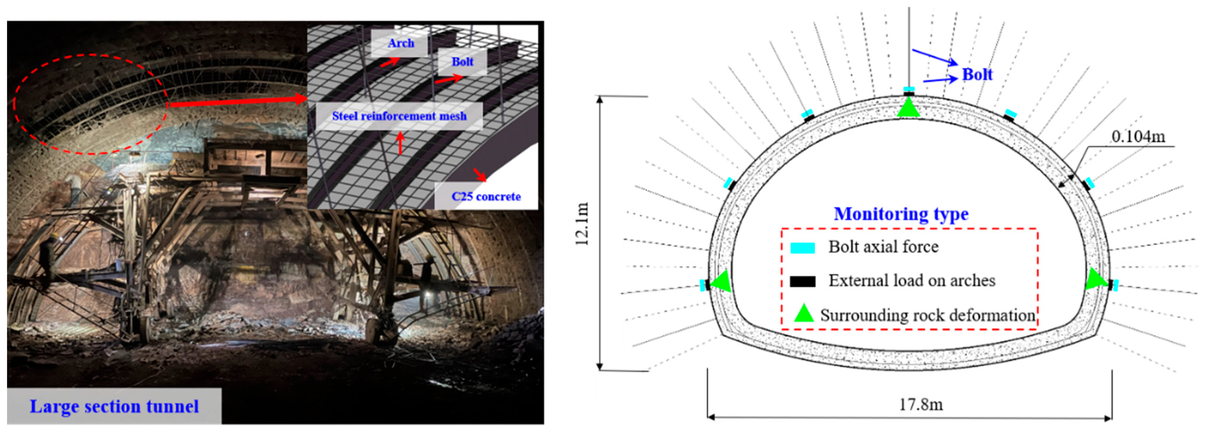
Based on the same numerical simulation experiment of a large-section tunnel in weak surrounding rock in eastern China, a field test was conducted on the prestressed active support of tunnel surrounding rock. Based on the indoor test results, three prestressing schemes were designed with unchanged parameters such as the spacing between bolts: a no-prestress scheme (Scheme A), a 50 kN prestress scheme applied using the torque method (Scheme B), and a 100 kN prestress scheme applied using a tensioning machine (Scheme C). Monitoring of the tunnel surrounding-rock support system includes monitoring of bolt axial forces, arch external load, and surrounding rock displacement.
The arrangement of monitoring elements is shown in Figure 10. The radial solid line in the figure represents the bolts within the current cross-section, and the radial dashed line represents the projection of adjacent longitudinal rows of bolts on the cross-section, used to reflect the staggered arrangement of bolts along the longitudinal direction of the tunnel. The bolt force gauges were arranged on the monitoring bolts of the arch crown, left and right arch shoulders, left and right arch waists, and left and right side walls, respectively, to measure the changes in axial force of the bolts under different support schemes. The pressure box was arranged on the outer side of the arch corresponding to the same location mentioned above, which was used to monitor the pressure transmitted to the arch during the deformation process of the surrounding rock. The displacement measurement points of the surrounding rock were arranged at the positions of the arch top and the left and right side walls, respectively, to monitor the deformation of the surrounding rock.
Figure 10.
Monitoring arrangement scheme of support system.
4.2. Analysis of Monitoring Results
4.2.1. Analysis of Support Forces
- Analysis of bolt axial force
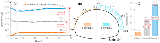
To compare and analyze the stress conditions of bolts under different prestress methods, an analysis was conducted on the bolts at the tunnel vault. Axial force–time curves of the bolts were obtained, as shown in Figure 11.
Figure 11.
Monitoring results of bolt axial force. (a) Axial force-time curves of vault bolt; (b) Outline diagram of bolt axial force; (c) Comparison of mean axial force of bolt.
According to the analysis in Figure 11, the axial force of the anchor bolt in the no-prestress scheme (Scheme A) shows an overall trend of first increasing and then stabilizing. The stabilized axial force in Scheme A is 11.9 kN. For schemes with prestressing (Scheme B and Scheme C), the axial force of bolts was affected by excavation disturbances, leading to a loosening of the axial force, followed by an increasing trend. In Scheme B, with a prestressing torque of 50 N·m applied, the initial axial force was 56.5 kN, and after 4 days, the axial force loss was 8.0 kN. The axial force loss rate, defined as the percentage of bolt axial force lost due to excavation disturbances relative to the initial axial force, is 14.2% for Scheme B. Similarly influenced by excavation disturbances, Scheme C, which applied prestress through tensioning, has an axial force loss rate of 8.5%, which is significantly lower than the torque-based prestressing method in Scheme B.
The stable axial forces of the arch top bolts in Schemes A, B, and C are 12.1 kN, 49.4 kN, and 95.2 kN, respectively. The average axial forces of the bolts are 11.9 kN, 49.1 kN, and 95.0 kN, respectively. The average axial forces of the bolts in Schemes B and C increased by 37.2 kN and 83.1 kN, respectively, compared to Scheme A, and the strength utilization rate increased by 15.80% and 35.29%, respectively. The application of prestress significantly improved the strength utilization rate of the bolt support, thereby enhancing the overall load-bearing performance of the support system.
- 2.
- Analysis of arch external load
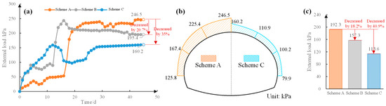
To compare and analyze the impact of different prestress conditions on the load-bearing behavior of the arch, the arch external load at the tunnel vault was monitored and analyzed. The curves of arch external load–time are shown in Figure 12. Meanwhile, a statistical analysis was conducted on the average external load at the arch vault and various monitoring positions.
Figure 12.
Curves of arch external load–time. (a) External load-time curves of arch at vault; (b) Outline diagram of external load on arch; (c) Comparison of average external loads.
As shown in Figure 12, the arch external load in all three schemes initially shows an overall increasing trend during the monitoring period. From days 10 to 15, influenced by the second disturbance caused by the step excavation method, the arch’s force undergoes a redistribution phenomenon. In Scheme A, the arch force experiences a sudden increase followed by stabilization. In Scheme B, the arch force undergoes a sudden increase followed by a slow decline. In Scheme C, the arch external load abruptly drops, then rises, and finally stabilizes.
The stress on the arch crown of Schemes A, B, and C after stabilization is 246.5 kPa, 195.4 kPa, and 160.2 kPa, respectively. The average stress on the arch is 192.3 kPa, 157.3 kPa, and 113.6 kPa, respectively. The stress on the arch of Schemes B and C is reduced by 18.2% and 40.9%, respectively, compared to Scheme A. The above monitoring results indicate that higher prestress helps the surrounding rock bear more load, reducing the impact of force redistribution during the second excavation using the step method.
4.2.2. Analysis of Surrounding Rock Deformation
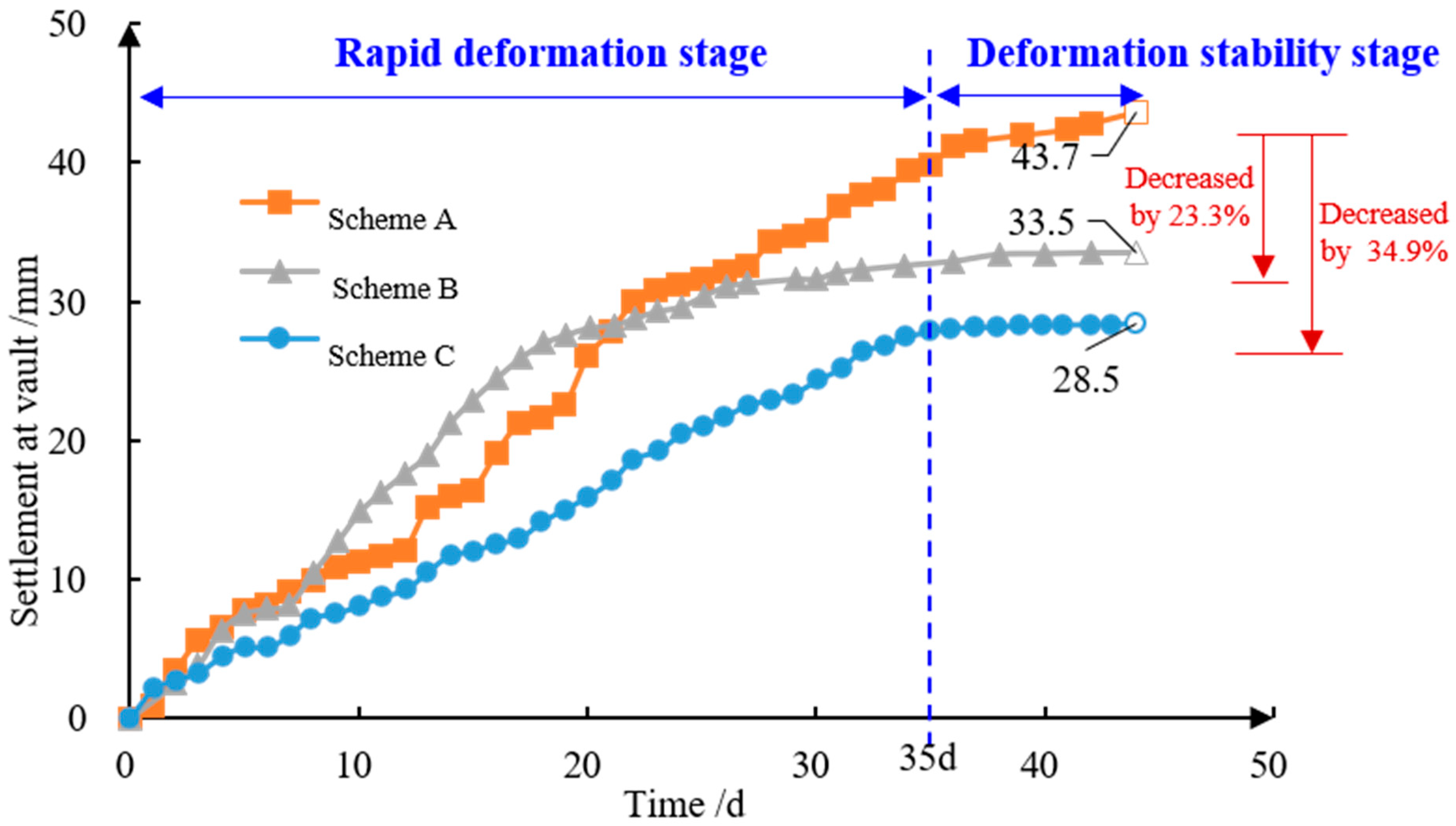
To compare and analyze the deformation control effects of different prestress methods on the surrounding rock, continuous monitoring of the displacement at the tunnel vault was conducted. The resulting crown settlement–time curve is shown in Figure 13.
Figure 13.
Surrounding rock deformation–time curves.
As shown in Figure 13, the deformation of the surrounding rock can be divided into two stages. In the rapid deformation stage, the rock displacement continues to increase. Subsequently, the vault settlement stabilizes after 35 days of excavation. For the prestressed Schemes B and C, the rock deformations are 33.5 mm and 28.5 mm, respectively, reducing by 23.3% and 34.9%, compared to the non-prestressed Scheme A. The on-site monitoring results demonstrate that higher prestress values applied to the bolts lead to better control of surrounding rock deformation, confirming the effectiveness of prestressed support.
4.3. Summary
Based on the indoor test results and relying on the large-section traffic tunnel site, an active support field test was carried out using different prestress methods. Three deployment schemes were adopted: Scheme A, without prestress; Scheme B, with a torque-method prestress of 50 kN; and Scheme C, with tension-method prestress of 100 kN. The monitoring results of Scheme A, B, and C are as follows:
- (1)
- In terms of the stress on the arch bolt, the application of prestress significantly improves the strength utilization rate of the bolt support, which can increase the strength utilization rate of the bolt by 35.29%, thereby improving the overall load-bearing performance of the support system.
- (2)
- In terms of the stress on the arch crown, the higher the applied prestress, the more effective the self-bearing capacity of the surrounding rock. The external load on the arch is reduced by 40.9%. During the secondary excavation of the step method, the influence of external load on the stress redistribution of the arch will be reduced.
- (3)
- In terms of the deformation of surrounding rock, on-site monitoring results show that the higher the prestress applied to the bolt, the better the control effect of the surrounding rock deformation in the support system, and the arch crown settlement is reduced by 34.9%, verifying the control effect of prestressed support.
4.4. Discussion
The existing research on the prestressed support of large-section tunnels mainly focuses on the control effect of prestressed bolts on the deformation of surrounding rock, the evolution of plastic zones, and the stress characteristics of support structures, as well as the optimization of parameters such as bolt length, spacing, and prestressing level. Related research has shown that prestressed bolts can actively constrain early loosening deformation of surrounding rock, improve the stress state of supporting structures, and enhance the self-bearing capacity of surrounding rock. However, existing research is mostly based on numerical simulations and indoor tests, and the level of prestressing research is relatively low. The prestress application method is difficult to meet the high-prestressed active support requirements of large-section tunnel engineering sites. However, there is still a lack of on-site test research on the effectiveness of high-prestressed bolt support and its synergistic mechanism with passive support.
Based on this, this paper conducts research on prestressed active support around the case of a large-section traffic tunnel, in accordance with the demand for high-prestressed active support in large-section tunnels. A numerical simulation experiment on prestressed support, a bolt prestressing conversion test, and field application research on large-section tunnels were conducted, indicating that high prestressing can maximize the active support effect of bolts and effectively regulate the active and passive coordinated support effect of surrounding rock. This research has achieved three innovations:
- (1)
- Through a numerical simulation analysis of the deformation, plastic zone evolution, and stress changes of surrounding rock under different prestressing conditions, a prestressing range that meets the active support requirements of large-section tunnel surrounding rock was determined, providing a basis for the design of high-prestressed bolt support parameters.
- (2)
- Through prestress application and conversion tests, the stress and deformation characteristics of the bolt–wedge anchorage structure under high-prestress conditions were clarified, and it was verified that the structure can achieve stable application and maintenance of high prestress. It was also proved that the use of the tension method and a bolt–wedge anchorage structure can meet the requirements of high-prestress application in tunnel engineering sites.
- (3)
- Conducting active support tests on large-section tunnels, the axial force of bolts, support stress, and the deformation evolution of surrounding rock under the combined action of high-prestressed bolt active support and passive support, such as steel arches, were revealed. This indicates that active and passive support can exert the self-bearing capacity of surrounding rock through collaborative regulation, improve the overall stability of the support system, and provide an on-site basis for the design and construction parameter optimization of large-section tunnel support.
This research mainly focuses on bolts, wedge anchorage, and surrounding rock in large-section tunnels under specific engineering conditions. The research conclusions are applicable to the prestress range, torque–tensile force conversion relationship, and support parameters obtained from numerical simulations and laboratory tests. The tension–prestress conversion relationship is also affected by the properties of bolt materials, thread processing quality, friction conditions, lock form, and construction and installation quality. An on-site test for large-section tunnels was conducted, focusing on the anchor net spray and arch support system, specific surrounding rock conditions, and the bench excavation method.
Based on the above research, future studies can conduct high-prestress application, prestress loss, and long-term bearing performance tests for bolts with different diameters, strength grades, and anchoring forms and establish a tension–prestress conversion model considering the influence of lock types and construction errors. At the same time, complex conditions, such as blasting disturbance and cyclic loads, should also be considered. On-site monitoring and numerical analysis should be carried out to reveal the collaborative bearing mechanism of active and passive systems, such as high-prestressed bolts, shotcrete, and arches. Furthermore, a parameter optimization method for high-prestressed active and passive support with different surrounding rock conditions, section sizes, and construction methods is proposed, providing support and a reference for the rational design of large-section tunnel surrounding rock support under complex conditions.
5. Conclusions
- Numerical experiments were conducted on large-section tunnels under different prestressing conditions to clarify the influence mechanism of prestressing on surrounding rock stress, plastic zone distribution, and surrounding rock deformation. As the prestress increases from 0 kN to 100 kN, the maximum vertical compressive stress of the surrounding rock decreases by 0.25 MPa, the plastic zone area decreases by 85.1 m2, and the maximum deformation decreases by 59.33%. This indicates that high-prestressed anchor rods can effectively reduce the vertical stress and plastic zone area of surrounding rock, greatly improving the deformation control effect of surrounding rock.
- Two types of pretensioning methods, torque and tension, were tested for prestressing conversion efficiency. The prestress conversion efficiency applied by the torque method was 10.6 N·m/kN, and the maximum prestress applied was within 57 kN. The prestress applied by the tensioning method can reach 103.5 kN. Compared with the prestress applied by the torque wrench, the prestress applied by the tensioning method is higher, which can effectively utilize the bearing performance of the anchor bolt and better meet the requirements of actual engineering prestress application.
- Active support field tests were conducted using different prestress methods, revealing the control mechanism of prestress on the stress and deformation of the support structure and surrounding rock. The results show that compared with the no-prestress anchor bolt support scheme, applying high prestress can improve the utilization rate of anchor bolt strength by 35.29%, reduce the external load on the arch by 40.9%, and reduce the settlement of the arch crown by 34.9%. High prestress can fully utilize the mechanical properties of anchor bolts, improve the safety reserve of passive support, control the stability of surrounding rock, and provide reference for the safety support design of large-section tunnels under complex conditions.
- Based on the above research, it is concluded that high prestress can effectively improve the stability of tunnel surrounding rock. At the same time, the use of the tensioning method and a bolt–wedge anchorage combination structure can stably apply a prestress of more than 100 kN, meeting the active support requirements of high prestress for large-section tunnels. Therefore, in large-section tunnels with weak surrounding rock, large excavation spans, and difficulty in controlling surrounding rock deformation, it is recommended to use the tension method and a bolt–wedge anchorage combination structure to apply high prestress, which can fully exert the active support effect of anchor bolts and reduce the influence of surrounding rock load on passive support components, such as arches. This provides methods and technical support for optimizing the design of surrounding-rock active and passive support, ensuring the safe control of surrounding rock, and reducing construction costs.
Author Contributions
M.W.: Writing—original draft, Methodology, Investigation, and Funding acquisition. H.G.: Writing—original draft, Methodology, Funding acquisition, and Conceptualization. G.G.: Visualization, Project administration, and Investigation. Z.B.: Writing—original draft and Data curation. C.X.: Writing—original draft and Project administration. Z.Y.: Validation and Data curation. X.M.: Writing—original draft and Data curation. All authors have read and agreed to the published version of the manuscript.
Funding
This work was supported by the Science and Technology Program Project of the Shandong High-Speed Group Co., Ltd. (Grant No. HS2022B112).
Institutional Review Board Statement
Not applicable.
Informed Consent Statement
Not applicable.
Data Availability Statement
Some or all data, models, or code that support the findings of this study are available from the corresponding author upon reasonable request.
Conflicts of Interest
Authors Mingfa Wang, Guangming Guo, Changjin Xu, and Xinjie Man were employed by Shandong Hi-Speed Infrastructure Construction Co., Ltd. and Shandong Hi-Speed Zilin Expressway Co., Ltd. The remaining authors declare that the research was conducted in the absence of any commercial or financial relationships that could be construed as a potential conflict of interest.
References
- He, M.C.; Wang, Q. Excavation compensation method and key technology for surrounding rock control. Eng. Geol. 2022, 307, 106784. [Google Scholar] [CrossRef] [Scilit]
- Qu, C.Q.; Xue, Y.G.; Qiu, D.H.; Zhang, G.D.; Liu, H.T. Research on General Model of Railway Route Selection in CSM Areas Using the Sichuan–Tibet Railway and Other Typical Mountain Railways as Case Studies. J. Transp. Eng. Part A Syst. 2023, 149, 04023054. [Google Scholar] [CrossRef] [Scilit]
- Tian, X.X.; Song, Z.P.; Wang, H.Z.; Zhang, Y.W.; Wang, J.B. Evolution characteristics of the surrounding rock pressure and construction techniques: A case study from Taoshuping tunnel. Tunn. Undergr. Space Technol. 2022, 125, 104522. [Google Scholar] [CrossRef] [Scilit]
- Wang, Q.; Xin, Z.X.; Jiang, B.; Zhang, H.B.; Xiao, Y.C.; Bian, W.H.; Li, L.N. Comparative experimental study on mechanical mechanism of combined arches in large section tunnels. Tunn. Undergr. Space Technol. 2020, 99, 103386. [Google Scholar] [CrossRef] [Scilit]
- Yu, X.Z.; Mou, R.F. System modeling and risk analysis of the Sichuan–Tibet Railway project. J. Transp. Eng. Part A Syst. 2021, 147, 04021094. [Google Scholar] [CrossRef] [Scilit]
- Jiang, B.; Xin, Z.X.; Zhang, X.F.; Deng, Y.S.; Wang, M.Z.; Li, S.D.; Ren, W.T. Mechanical properties and influence mechanism of confined concrete arches in high-stress tunnels. Int. J. Min. Sci. Technol. 2023, 33, 829–841. [Google Scholar] [CrossRef] [Scilit]
- Zhang, D.L.; Sun, Z.Y.; Fang, Q. Scientific problems and research proposals for Sichuan–Tibet railway tunnel construction. Undergr. Space 2022, 7, 419–439. [Google Scholar] [CrossRef] [Scilit]
- Huang, Y.B.; Wang, Q.; Gao, H.K.; Jiang, Z.H.; Li, K.; Chen, K. Failure mechanism and construction process optimization of deep soft rock chamber group. J. China Univ. Min. Technol. 2021, 50, 69–78. [Google Scholar] [CrossRef]
- Zhang, D.L.; Xu, T.; Fang, H.C. Analytical modeling of complex contact behavior between rock mass and lining structure. J. Rock Mech. Geotech. Eng. 2022, 14, 813–824. [Google Scholar] [CrossRef] [Scilit]
- Jiang, K.; Liu, Z.; Wang, Y.; Tian, Y.; Zhang, C.; Zhang, T. Effects of different friction coefficients on input torque distribution in the bolt tightening process based on the energy method. J. Tribol. 2022, 144, 071203. [Google Scholar] [CrossRef] [Scilit]
- Sun, Z.Y.; Zhang, D.L.; Fang, Q.; Huangfu, N.Q.; Chu, Z.F. Convergence-confinement analysis for tunnels with combined bolt–cable system considering the effects of intermediate principal stress. Acta Geotech. 2023, 18, 3323–3348. [Google Scholar] [CrossRef] [Scilit]
- Lu, W.; Meng, L.X.; Li, S.C.; Xu, Y.D.; Wang, L.; Zhang, P.; Dou, S.T.; Sun, H.B. Study on progressive failure behavior and mechanical properties of tunnel arch support structures. Tunn. Undergr. Space Technol. 2023, 140, 105285. [Google Scholar] [CrossRef] [Scilit]
- Li, L.P.; Shang, C.S.; Chu, K.W.; Zhou, Z.Q.; Song, S.G.; Liu, Z.H.; Chen, Y.H. Large-scale geo-mechanical model tests for stability assessment of super-large cross-section tunnel. Tunn. Undergr. Space Technol. 2021, 109, 103756. [Google Scholar] [CrossRef] [Scilit]
- Li, G.; Hu, Y.; Tian, S.M. Analysis of deformation control mechanism of prestressed anchor on jointed soft rock in large cross-section tunnel. Bull. Eng. Geol. Environ. 2021, 80, 9089–9103. [Google Scholar] [CrossRef] [Scilit]
- Wang, Q.; Wu, W.R.; Wang, Y.T.; He, M.C.; Xue, H.J.; Wei, H.Y. Evolution and control mechanism of rockburst in rock anchored by new energy-absorbing material. Rock Mech. Rock Eng. 2023, 56, 4569–4582. [Google Scholar] [CrossRef] [Scilit]
- Yuan, H.; Shan, R.; Su, X. Deformation characteristics and stability control of a gateroad in fully mechanized mining with large mining height. Arab. J. Geosci. 2018, 11, 767. [Google Scholar] [CrossRef] [Scilit]
- Li, A.; Dai, F.; Wu, W.; Liu, Y.; Liu, K.; Wang, K. Deformation characteristics of sidewall and anchorage mechanisms of prestressed cables in layered rock strata dipping steeply into the inner space of underground powerhouse cavern. Int. J. Rock Mech. Min. Sci. 2022, 159, 105234. [Google Scholar] [CrossRef] [Scilit]
- Wang, Q.; Xu, S.; Xin, Z.X.; He, M.C.; Wei, H.Y.; Jiang, B. Mechanical properties and field application of constant resistance energy-absorbing anchor cable. Tunn. Undergr. Space Technol. 2022, 125, 104526. [Google Scholar] [CrossRef] [Scilit]
- He, M.C.; Wang, Q.; Wu, Q. Innovation and future of mining rock mechanics. J. Rock Mech. Geotech. Eng. 2021, 13, 1–21. [Google Scholar] [CrossRef] [Scilit]
- Cao, J.; Zhang, N.; Wang, S.; Qian, D.; Xie, Z. Physical model test study on support of super pre-stressed anchor in the mining engineering. Eng. Fail. Anal. 2020, 118, 104833. [Google Scholar] [CrossRef] [Scilit]
- Jiang, B.; Ma, F.L.; Wang, Q.; Gao, H.K.; Zhai, D.H.; Deng, Y.S.; Xu, C.J.; Yao, L.D. Drilling-based measuring method for the c-φ parameter of rock and its field application. Int. J. Min. Sci. Technol. 2024, 34, 65–76. [Google Scholar] [CrossRef] [Scilit]
- Lv, C.; Liu, A.; Liu, D.; Zhang, F.; Yang, W. Study on the load conversion of bolt-nut fasteners between tightening and service conditions. Exp. Tech. 2021, 45, 721–734. [Google Scholar] [CrossRef] [Scilit]
- Meng, X.Z. Laboratory studies of the mechanical properties of bolt thread connection. Adv. Mater. Res. 2013, 724–725, 1740–1744. [Google Scholar] [CrossRef] [Scilit]

Disclaimer/Publisher’s Note: The statements, opinions and data contained in all publications are solely those of the individual author(s) and contributor(s) and not of MDPI and/or the editor(s). MDPI and/or the editor(s) disclaim responsibility for any injury to people or property resulting from any ideas, methods, instructions or products referred to in the content. |
© 2026 by the authors. Licensee MDPI, Basel, Switzerland. This article is an open access article distributed under the terms and conditions of the Creative Commons Attribution (CC BY) license.