


Abstract
(1) Background: HTPLA FDM-printed cutting guides enable the low-cost, in-hospital production of patient-specific instruments. However, annealing, which is required for steam sterilization, may alter the dimensions of fit-critical fixation pin holes. (2) Methods: HTPLA cylindrical specimens (height 5 mm) were printed with fixed process parameters and vertical orientation. Inner diameter (1.6–5.0 mm) and wall thickness (2–6 mm) were varied using a two-factor Central Composite Design (n = 13). Following a two-stage annealing treatment (80 °C, 10 min; 100 °C, 50 min), post-annealing dimensions were measured and modeled using Response Surface Methodology. An illustrative verification was performed on additional specimens. (3) Results: Annealing induced a systematic decrease in inner diameter (−0.4 to −0.9 mm) and an increase in wall thickness (+0.1 to +0.4 mm). A reduced quadratic model accurately captured these trends within the investigated range, with small residuals observed during verification (≤0.1 mm). (4) Conclusions: The proposed local, geometry-driven model supports compensation in fixation pin-hole dimensions in annealed HTPLA cutting guides, improving dimensional predictability within a defined design and process window.
1. Introduction
Three-dimensional (3D) printing, also known as additive manufacturing (AM), is a process based on the layer-by-layer deposition of material to build objects directly from digital Computer Aided Design (CAD) models. Since its introduction in the 1980s, with Chuck Hull’s stereolithography (SLA) patent [1], 3D printing has rapidly evolved from a rapid-prototyping technology [2] into a key tool in the aerospace, automotive, fashion, and medical sectors [3,4,5,6,7], enabling the construction of precise and complex shapes with high design freedom.
AM enables reduced overproduction, shorter supply chains, and lower material waste, especially for small, customized plastic components. Among AM technologies, Fused Deposition Modeling (FDM) is the most accessible and cost-effective [8], offering design flexibility, low equipment and material costs, and compatibility with numerous thermoplastics [9,10]. Over recent years, advances in filament development have improved manufacturability and surface quality. In particular, Polylactic Acid (PLA), a semicrystalline biopolymer, has gained widespread use due to its versatility, from biodegradable packaging and disposable goods to medical devices and personal care applications [11].
In healthcare, 3D printing has been used since the early 1990s, initially for the reconstruction of cranial models from Computer Tomography (CT) scans [12]. Now, it is widely adopted across multiple surgical fields, including oral and maxillofacial, cardiothoracic, plastic, neurosurgical, and orthopedic surgery [13,14,15,16,17,18]. This technology enables the cost-effective production of customized prosthetics, implants, dental devices, and anatomical models to support virtual surgical planning (VSP) [7,19]. More recently, it has also supported the creation of patient-specific instruments (PSIs), such as surgical cutting guides, further improving precision and personalization in clinical practice [20,21,22].
However, the overall accuracy of PSIs is influenced by multiple sources of geometric uncertainty along the digital workflow, including image acquisition, segmentation, and surface reconstruction, as CT-based bone models may already introduce non-negligible deviations from true anatomy [23].
Particularly in orthopedics, 3D-printed cutting guides, also referred to as drilling guides or surgical templates, assist surgeons by defining screw and wire trajectories, osteotomy orientation, and resection margins in bone tumor surgery [24,25], where accurate positioning of cutting planes is critical and relies on precise geometric modeling [26]. These guides enhance precision, safety, and reproducibility, simplifying complex procedures and supporting the accurate execution of the VSP. In pediatric orthopedics, their use has been associated with reduced operating time, fluoroscopy exposure, blood loss, and complication rates, together with improved surgical accuracy and overall efficiency [27,28,29,30]. Additionally, cutting guides support surgical training by providing structured intraoperative guidance and increasing confidence during complex procedures [31,32,33].
Efficient sterilization remains a key challenge for the clinical adoption of 3D-printed parts, particularly those made of polymeric materials such as PLA. Steam sterilization is currently the most widely adopted method for 3D-printed PSIs in hospital settings, owing to its reliability, standardization, and broad availability within routine clinical workflows [34,35]. Although exposure to elevated temperatures may induce dimensional deformation in polymer-based components, steam sterilization is increasingly integrated into clinical 3D printing workflows due to its cost-effectiveness and ease of implementation.
Alternative low-temperature sterilization techniques, including ethylene oxide (EtO), hydrogen-peroxide plasma, and peracetic acid, have been reported for polymeric medical devices; however, their adoption may be constrained by longer processing times, higher costs, material compatibility issues, and limited availability in hospital environments [34].
Generally, PLA offers good print quality and stiffness but has a low glass transition temperature, making it unable to maintain shape at moderate heat and unsuitable for thermal or steam sterilization [36]. To address these limitations, High-Temperature PLA (HTPLA) incorporates crystallization agents that enhance thermal stability and mechanical performance. After thermal annealing, HTPLA gains strength, dimensional stability, and heat resistance, enabling compatibility with autoclave sterilization without the associated deformation [37].
Among post-processing techniques for FDM parts, annealing is one of the most effective. By increasing crystallinity, it reduces internal stresses, improves interlayer adhesion, and enhances mechanical properties [38,39,40,41]. In PLA, higher crystallinity increases flexural strength, depending on the annealing temperature and heating/cooling cycles [42,43]. However, annealing can also induce dimensional changes, making shrinkage or expansion effects relevant design considerations [44].
Despite its improved thermal resistance compared to standard PLA, HTPLA remains a polymer-based material whose mechanical behavior differs substantially from that of metallic guides and high-performance engineering polymers. PLA is intrinsically brittle, typically exhibiting limited elongation at break and reduced fracture toughness [45]. Although annealing can enhance certain properties, the heat deflection temperature and mechanical stability of PLA-based materials remain lower than those of metallic guides, potentially raising concerns regarding fragmentation or debris generation when subjected to localized thermal loads [46].
These material characteristics impose specific constraints on the design of polymeric PSIs, particularly with respect to dimensional accuracy, fixation stability, and interaction with surgical tools.
The design of 3D-printed cutting guides is highly case-specific and difficult to fully standardize, as each procedure presents unique anatomical and surgical requirements [47]. Several design pipelines for patient-specific orthopedic devices, including statistical shape model-based approaches and structured CAD workflows for custom cutting guide design, rely on high geometric fidelity to ensure accurate translation from virtual planning to physical devices. Consequently, dimensional stability during manufacturing and post-processing represents a non-negligible constraint in the overall accuracy chain [48,49,50]. Nonetheless, certain functional features, such as fixation pins, screw trajectories, and osteotomy orientation, are recurrent and critical to ensure accurate reproduction of the preoperative plan [51]. Since dimensional changes may occur after annealing and before sterilization, geometry-driven design strategies that anticipate these effects are required to avoid instability or misalignment during surgery.
Several studies have investigated the dimensional stability of PLA-based materials after annealing, primarily focusing on global shrinkage behavior, crystallinity changes, or the optimization of thermal treatment parameters using standardized or generic benchmark specimens [52,53]. While these studies provide important insights into material behavior, they rarely address how post-processing deformation affects local, functionally critical features of patient-specific instruments [23,26,49]. In particular, the impact of dimensional changes on fixation pin holes in polymer-based cutting guides remains comparatively less explored, especially within clinically oriented, in-hospital manufacturing workflows, where small geometric deviations may have a disproportionate effect on guide stability and surgical reproducibility.
In this context, the present study aims to establish preliminary design guidelines by focusing on one key feature: the fixation pin holes. The work experimentally evaluates how the manufacturing and annealing process affects their final dimensions and develops a regression model to estimate post-processing shrinkage, helping designers select the appropriate nominal hole diameters during the CAD phase and ensure accurate pin fit, guide stability, and surgical precision.
2. Materials and Methods
This work focuses on improving the dimensional precision of the holes of the cutting guides used for pins. By varying the initial hole diameter and wall thickness, a predictive model was developed to help compensate for the dimensional reduction occurring after the annealing phase of the process. This approach allows designers to define appropriate nominal dimensions in advance, ensuring that the final printed components meet the requirements defined during the VSP phase.
All process-related parameters, including print orientation, infill strategy, and annealing setup, were intentionally kept constant to isolate the effect of the local geometric variables investigated in this study.
2.1. Process Workflow
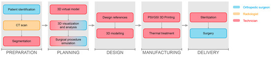
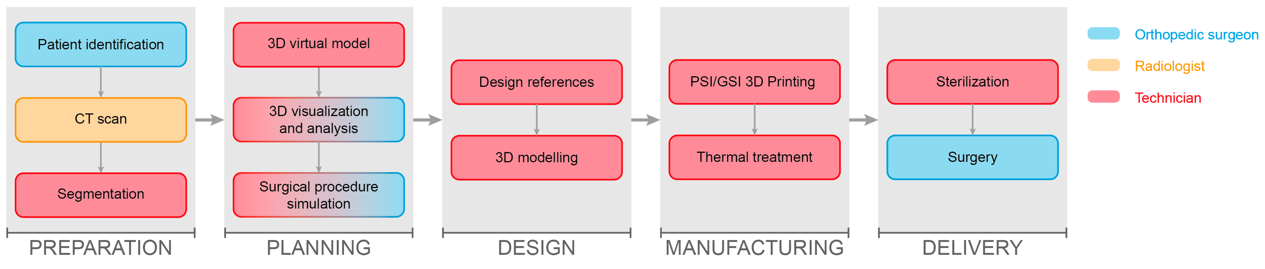
Our well-established PSI manufacturing process [54] (Figure 1) began with a preparation phase, which included a surgical request and the acquisition of the patient’s CT scan. Imaging data were processed using Materialise Mimics (Materialise NV, Leuven, Belgium) to segment the region of interest and generate a 3D virtual model of the target bone, which was then exported as an STL file.
Figure 1.
Overview of the workflow simplified to the main steps from patient selection to 3D printing and surgery.
Preoperative planning was subsequently performed in Blender (Blender Foundation, Amsterdam, The Netherlands), in close collaboration with the requesting surgeon. During this stage, key surgical parameters were defined, including correction angles, cutting planes, fixation wire dimensions and placement, cutting guide positioning, and surgical approach. Critical considerations also included nearby soft tissues and vital anatomical structures to be preserved. The entire surgical workflow was assessed, taking into account anatomical and clinical constraints as well as the instrumentation available in the operating room, including fixation plates when required. The available bone surface for accurate PSI placement was carefully evaluated.
Once all planning elements had been defined, the 3D model and surgical specifications were used to design the PSIs in Creo Parametric (PTC Inc., Boston, MA, USA). Design parameters were set based on the features and constraints identified during planning. Attention was paid to the diameter of the fixation wire holes, which represented the specific focus of this study.
The cutting guides designed were subsequently manufactured using an FDM Bambu Lab X1 Carbon 3D printer (Bambu Lab, Shenzhen, China), using HTPLA filament (Filamentum Manufacturing Czech s.r.o., Hulín, Czech Republic). Material selection and optimized printing parameters were established in previous studies [37]. The main material properties and printing parameters are reported in Table 1 and Table 2.
Table 1.
Main Properties of HTPLA (PLA Crystal Clear, Fillamentum Manufacturing Czech).
Table 2.
Optimized printing parameters defined for HTPLA cutting guide 3D printing.
Following printing, the components underwent a thermal annealing cycle, as previously validated, to stabilize their geometry and enhance their mechanical properties and material strength. Specifically, annealing was performed in two phases: an initial stage at 80 °C for 10 min, followed by a second stage at 100 °C for 50 min. During annealing, specimens were positioned upright, with the cylindrical axis oriented vertically and perpendicular to the supporting surface, resting freely without external mechanical constraints. At the end of the annealing cycle, specimens were allowed to cool naturally to room temperature, without forced cooling.
The material behavior resulting from the cumulative effects of printing and annealing, from nominal CAD geometry to the final component, represented the phenomenon investigated in this study for the definition of design guidelines.
Finally, the finished instruments were sterilized and delivered directly to the operating room on the day of surgery.
2.2. Design of the Experiment
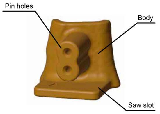
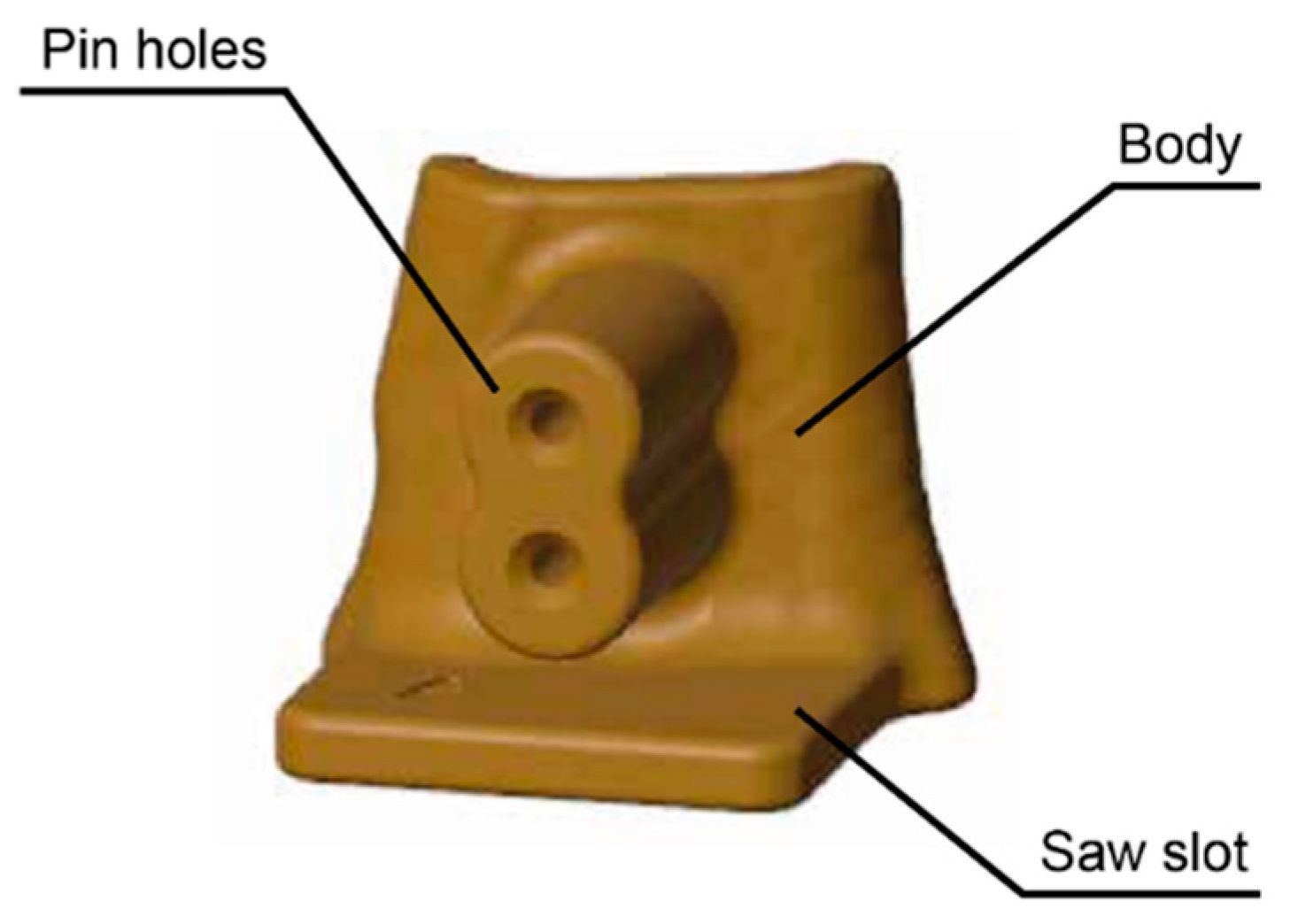
Cutting guides are extremely case-specific and therefore difficult to fully standardize, as previously discussed, due to the high level of customization required for each patient’s anatomy and the planned treatment. Nevertheless, some key elements have been identified, namely, the main body of the PSI, the fixation pin holes, and the saw slot, which is the feature that guides the surgical saw during the osteotomy (Figure 2).
Figure 2.
Illustrative example of a cutting guide showing its main structural features.
In this study, the fixation pin-hole feature was isolated and evaluated separately, allowing a focused investigation of its dimensional behavior throughout the manufacturing process.
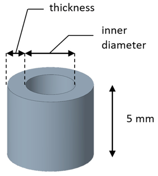
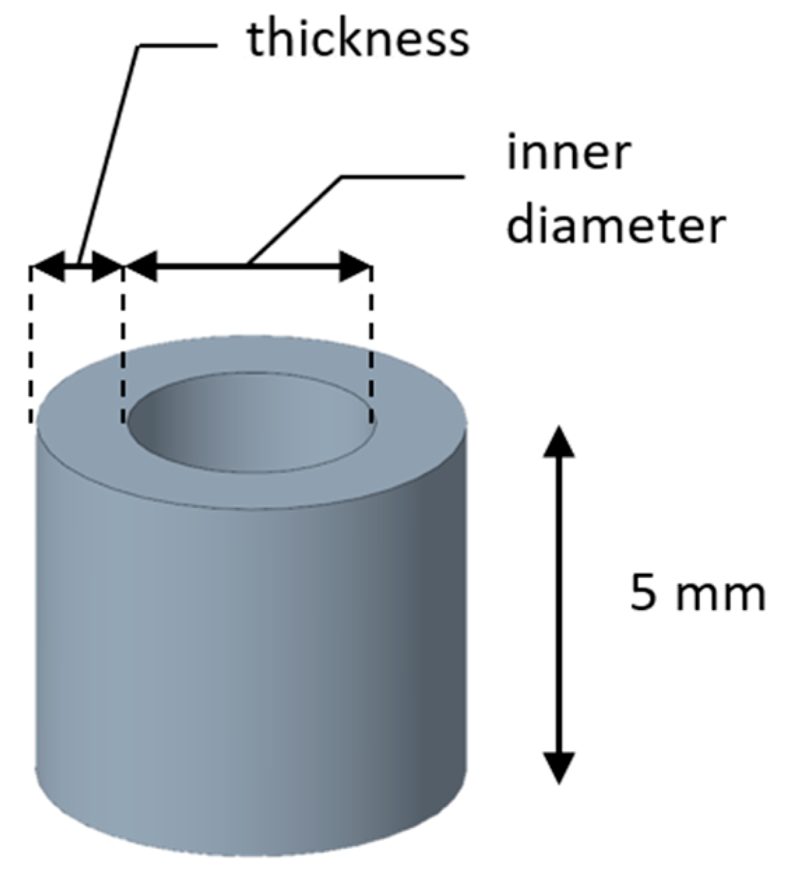
A set of specimens with varying dimensions was produced to collect data and establish the relationship between the planned and effective dimensions. The specimen height was fixed at 5 mm to standardize the geometry and exclude it as a variable, thereby focusing the analysis exclusively on inner diameter and hole thickness (Figure 3). After the 3D printing phase and subsequent annealing, the final dimensions were manually measured with a digital caliper. Response Surface methodology (RSM) was applied to derive an empirical relationship capable of predicting the final inner diameter of the annealed specimens within the practical range of parameter values. The purpose here was not to identify an optimization plateau, but rather to establish a usable relationship within the specific diameter range employed in practice.
Figure 3.
Three-dimensional representation of the specimen with a fixed height of 5 mm and variable inner diameter and thickness.
Thirteen 3D-printed samples were produced from the combination of the selected parameters for a comprehensive study. The investigated factors were inner diameter and wall thickness, each defined at a specific range of levels (“high” and “low”):
- The inner diameter was included as the main focus of the study to investigate how it changed from the initial design to the final post-process condition. The values ranged from 1.6 mm to 5 mm, which were selected based on surgical practice, reflecting the minimum and maximum diameters commonly used, in our experience, in the operating room, and ensuring that they could be reliably measured with a digital caliper at the end of the process, while accounting for a safety margin to accommodate shrinkage.
- Thickness was the second parameter considered, as the amount of material surrounding the inner diameter was expected to play a key role in the shrinkage results. The values were set between a minimum of 2 mm and a maximum of 6 mm.
To derive a compensation model accounting for dimensional variations induced by annealing, a response surface methodology was adopted. A Central Composite Design (CCD) was adopted, which extends a factorial design by adding center and axial points to capture curvature effects. For a two-factor, two-level design (four factorial points), the axial distance α was 1.414. Unlike a simple factorial design, which captures only linear effects and interactions, CCD enabled the modeling of both linear and quadratic terms, making it suitable for response surface analysis. According to the principles of CCD, replications were performed at the center point to ensure the stable variance of the predicted response and to allow for estimation of experimental error and model curvature, as recommended in the design-of-experiments literature [55]. While CCD is typically applied to identify an optimum point, in this study, it was used solely to develop a descriptive model, capturing the relationship between planned and effective dimensions within the practical range of values. The variable parameters and their levels are reported in Table 3.
Table 3.
High and low levels of variable parameters.
2.3. Measurements
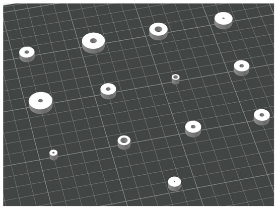
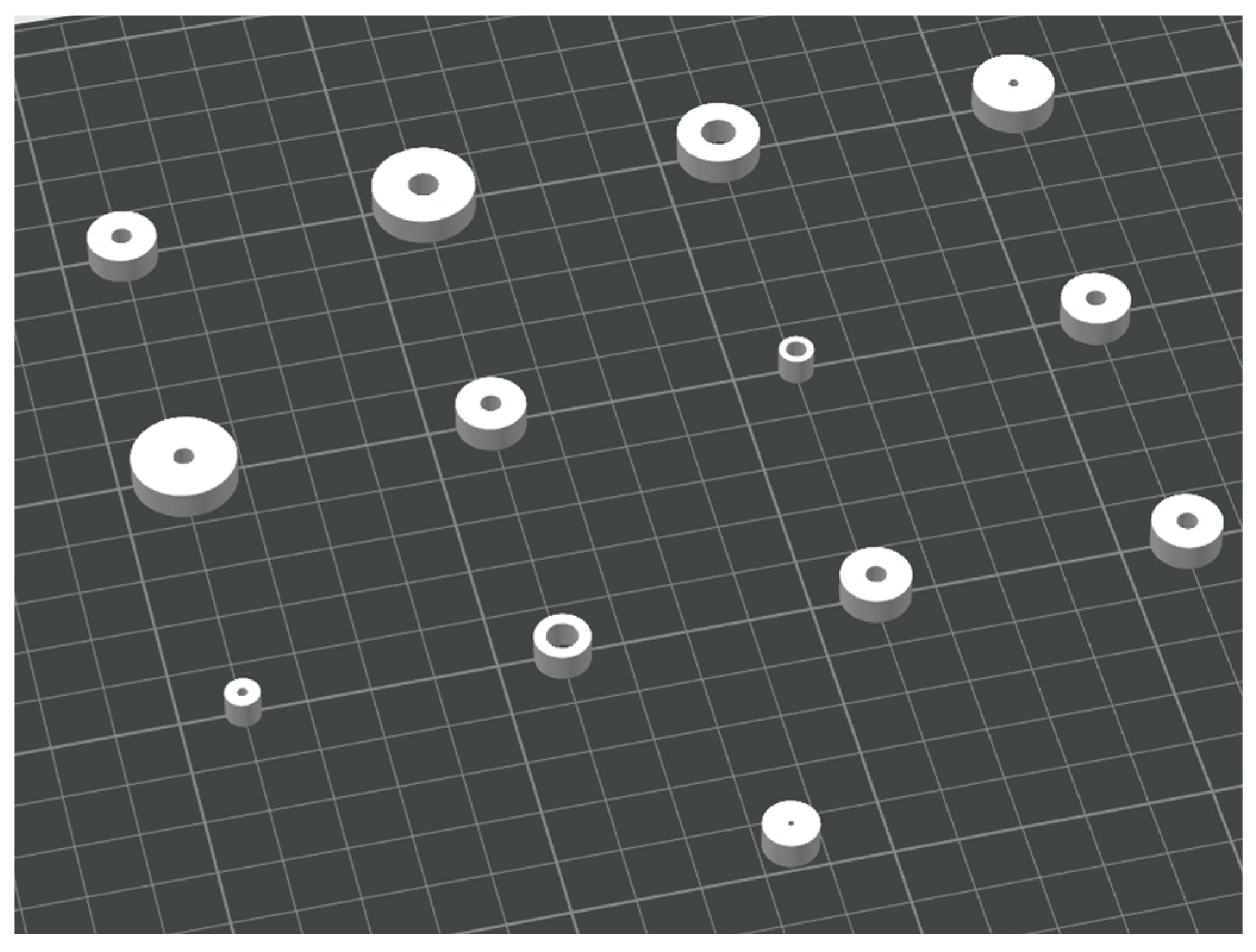
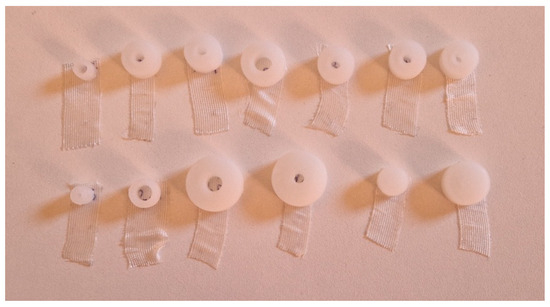
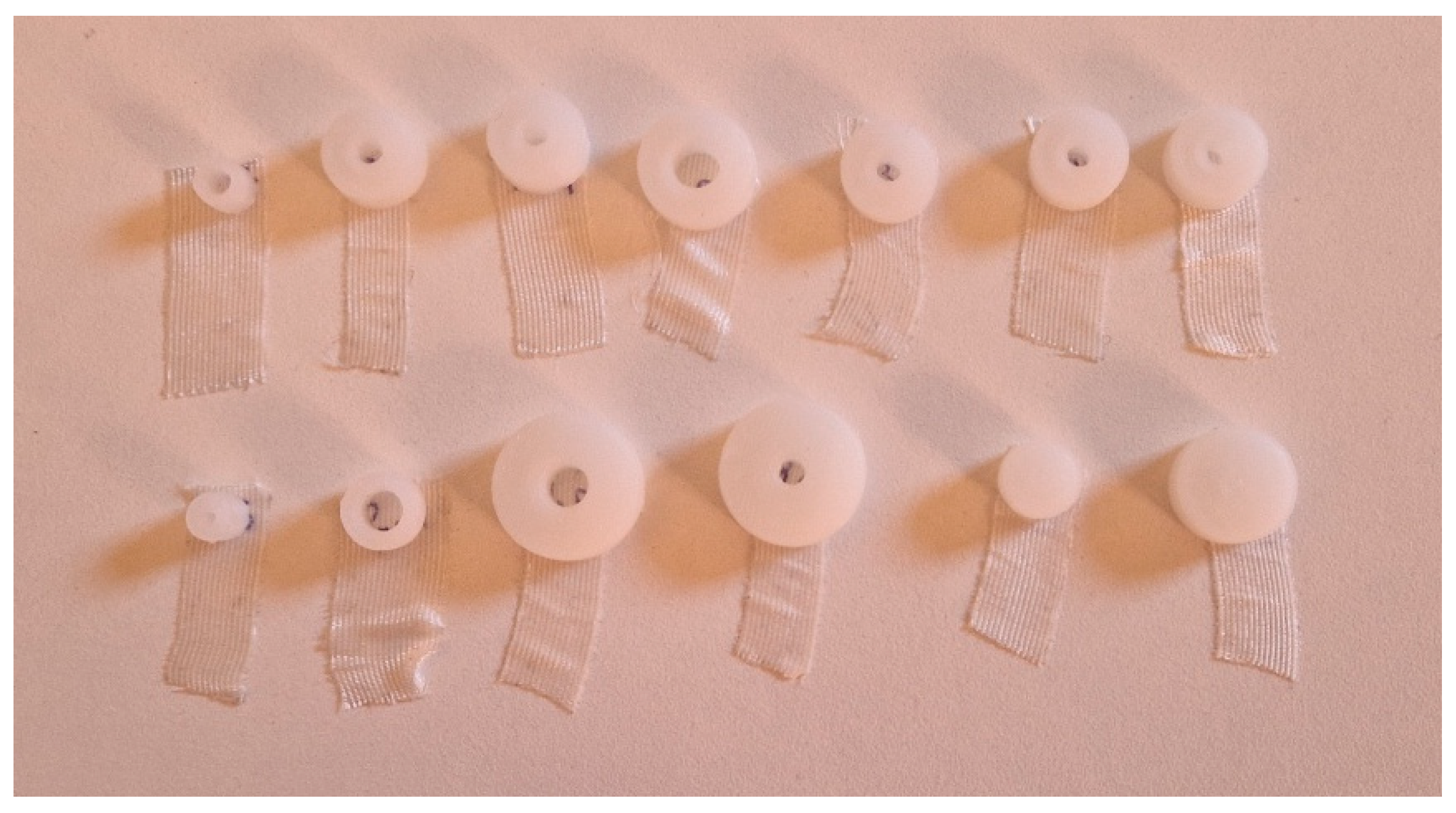
CAD models of each specimen were designed according to the design-of-experiments specifications. All specimens were 3D-printed, with the cylindrical axis oriented vertically, perpendicular to the supporting surface, and annealed in an upright position, resting in plane and without external constraints (Figure 4 and Figure 5). The proposed regression model was therefore valid only for this specific printing and annealing configuration, as different orientations may introduce additional deformation mechanisms, including ovalization.
Figure 4.
The 13 specimens randomly arranged on the build plate according to the randomized order.
Figure 5.
The 13 specimens after annealing, ready for measurement.
The effective values of inner diameter, thickness, and height (the latter not included as a design variable but monitored as a control) were manually measured three times by the same operator using a digital caliper, and the average values were used for the analysis. Measurement repeatability was estimated from repeated measurements, resulting in standard deviations on the order of 0.05 mm for both inner diameter and thickness. All reported deviations were obtained from physically measured, annealed specimens and compared with the nominal CAD dimensions (Table 4).
Table 4.
Central Composite Design of the experiments, including randomized run order, point type, and corresponding values (in mm). Please note that the height is maintained constant at 5 mm in the experiment.
From these measured dimensions, the corresponding volume was calculated, and the differences with respect to the designed geometry were then computed (Δinner, Δthickness, Δheight, Δvolume, and Δvolume%) to quantify the dimensional changes induced by the combined printing and annealing process (Table 5).
Table 5.
Final measurement (in mm) and values for each specimen.
3. Results
A preliminary inspection of the data clearly showed a consistent decrease in inner diameter, with measured reductions ranging from −0.4 to −0.9 mm, and a systematic increase in thickness, with variations between +0.1 and +0.4 mm. Specimen height exhibited a slight positive variation, despite being maintained as a constant design parameter, with measured increases between +0.2 and +0.3 mm. Overall, volumetric variations remained limited in percentage terms, suggesting that the dimensional changes were primarily associated with material redistribution rather than an actual loss of volume. Among the investigated dimensions, the reduction in inner diameter represented the most critical feature for the correct fit of pins.
The response of interest was the final inner diameter, considering the varied values for the experiment (inner diameter and thickness) as independent factors. The model fit summary (Table 6) indicated that the quadratic model was the most suitable for describing the variation in our response. The linear and 2FI models were not adequate, despite showing high R2 values, while the cubic model was aliased and therefore not considered. The quadratic model was statistically significant (p = 0.0129), with no significant lack-of-fit (p = 0.7698), and showed excellent agreement between adjusted R2 (0.9984) and predicted R2 (0.9973). Based on these results, the quadratic model was selected.
Table 6.
Fit summary for the choice of the model.
ANOVA results for the full quadratic model (Table 7) confirmed that the model was statistically significant (p < 0.0001). Among the individual terms, inner diameter showed the strongest effect on the final diameter (p < 0.0001), together with its quadratic term (p = 0.0047), indicating a non-linear relationship between nominal and final inner diameter. Conversely, the main effect of thickness was only marginally non-significant (p = 0.061), while the interaction (Inner Diameter×Thickness) and quadratic effect of thickness were clearly not significant.
Table 7.
ANOVA analysis for the full quadratic model.
Based on these results, a model reduction was performed to retain only the significant terms. The ANOVA of the reduced model (Table 8) confirmed that the simplified model remained highly significant (p < 0.0001) with no lack of fit (p = 0.8646). The retained terms included the following: the main effects of inner diameter and thickness, as well as the quadratic effect of inner diameter. Among these, inner diameter was by far the dominant factor (p < 0.0001), while thickness had a smaller but still significant effect (p = 0.0397). The quadratic term of inner diameter confirmed the presence of curvature in the relationship between nominal and final inner diameter. The interaction term and the quadratic term of thickness were excluded as they were not significant. The coefficients of determination confirmed the quality of the fit, with R2 = 0.9989, Adjusted R2 = 0.9986, and Predicted R2 = 0.9982, all in close agreement.
Table 8.
ANOVA analysis for model reduction.
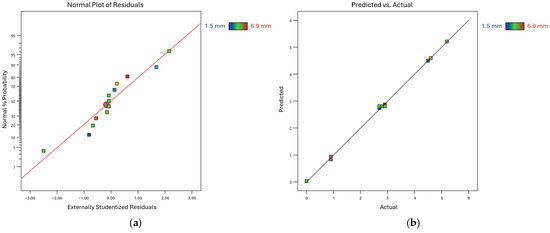
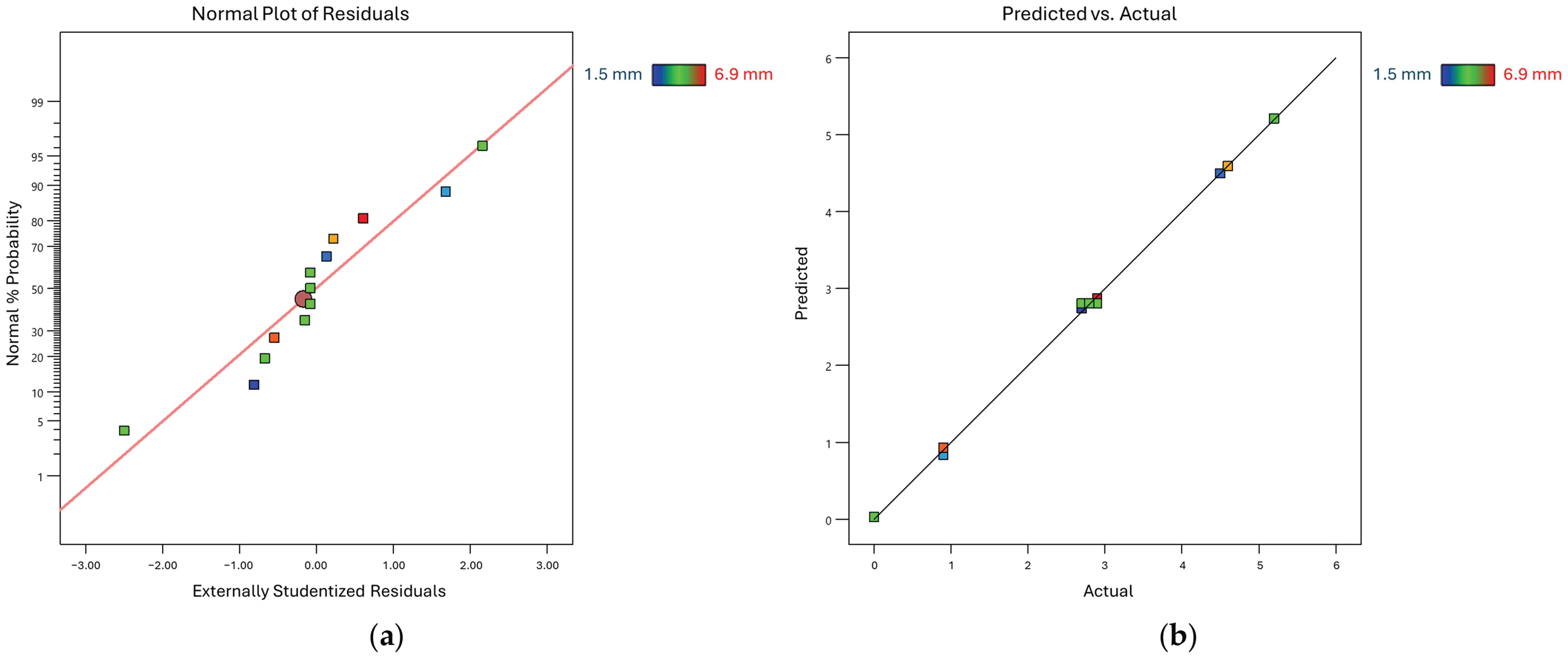
Diagnostic plots confirmed the adequacy of the model (Figure 6): residuals were approximately normally distributed, and the predicted versus actual plot showed that the experimental data aligned closely with the bisector, indicating an adequate description of the observed experimental trends.
Figure 6.
(a) Normal probability plot of residuals confirming the normal distribution of the data; (b) Predicted vs. actual plot demonstrating good agreement between the fitted model and the experimental data within the investigated design space.
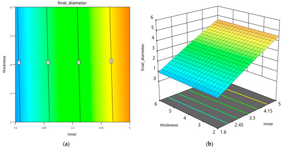
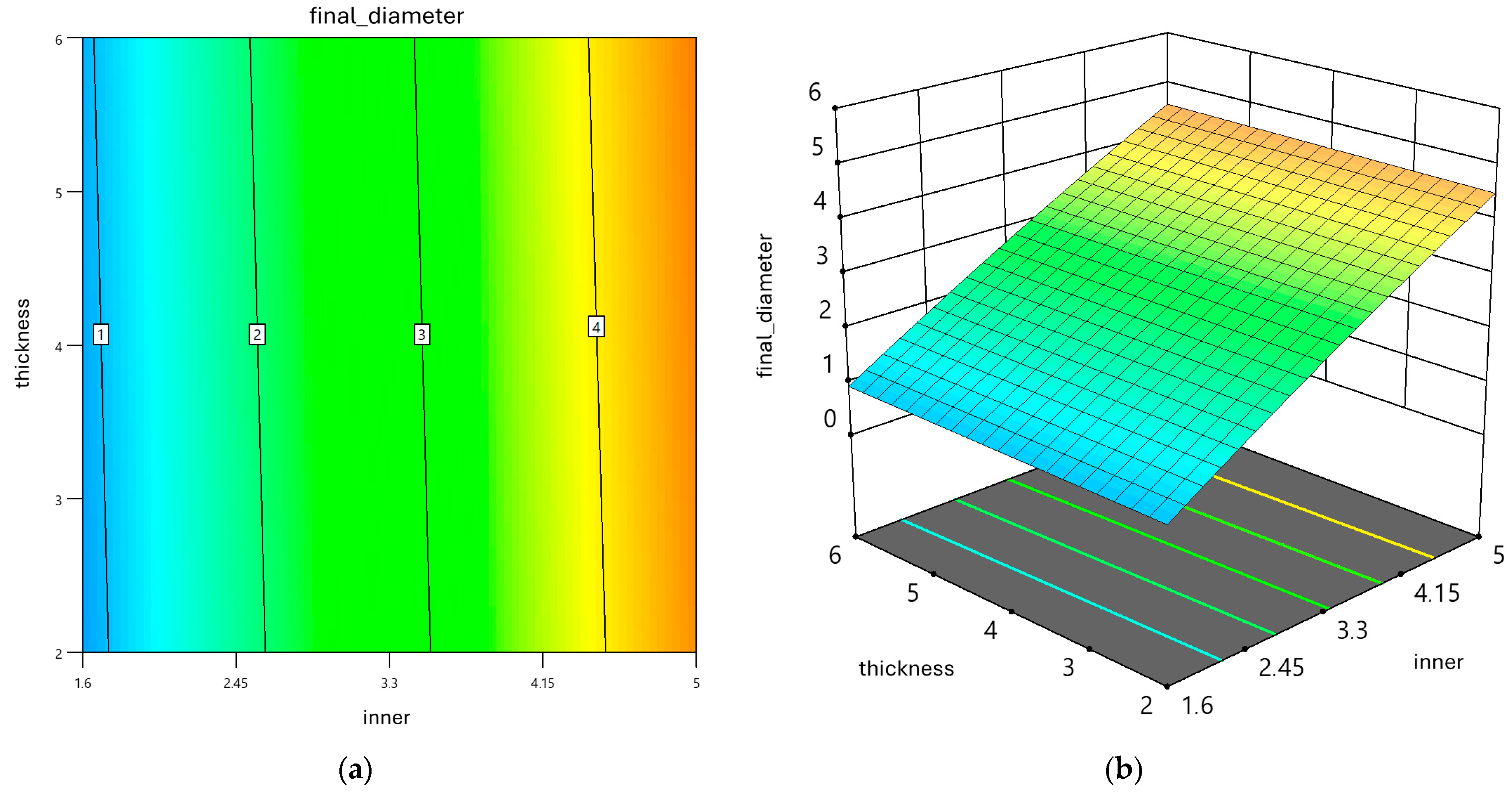
In addition, contour and response surface plots (Figure 7) illustrated the effect of nominal inner diameter and thickness on the final inner diameter. The plots clearly highlighted that inner diameter was the dominant factor, with a non-linear curvature confirmed by the quadratic term, while thickness had a smaller but significant effect. These graphical representations allowed a direct interpretation of how dimensional changes evolved across the design space and supported the use of the regression model as a local design-support relationship within the investigated parameter range.
Figure 7.
(a) Contour plot of the predicted final inner diameter as a function of inner diameter and thickness. Colors represent the predicted final diameter, while black contour lines indicate iso-diameter levels. Numbered labels (1–4) denote selected iso-diameter levels used as reference values; (b) Three-dimensional response surface of the predicted final inner diameter as a function of inner diameter and thickness, with the same color scale used in (a).
The reduced quadratic model resulted in the following regression equation:
final diameter = −1.20343 + 1.29346 × inner diameter + 0.023928 × thickness − 0.032722 × inner diameter2
In this context, “inner diameter” refers to the nominal inner diameter defined in the CAD, “thickness” to the nominal wall thickness of the hole, and “final diameter” to the effective diameter obtained after the annealing process. The model allows the prediction of the final diameter for any combination of design parameters within the experimental range. Its strength lies in the possibility of inverting the regression equation to determine the nominal CAD diameter required to achieve a specific post-annealing size. This makes the model not only predictive but also directly applicable as a compensation rule during design, supporting the definition of appropriate nominal pin-hole dimensions to achieve the desired fit after annealing.
The reported goodness-of-fit metrics should be interpreted in the context of a local response surface model and are not intended to imply broad predictive validity beyond the investigated design space.
For transparency, comparison between measured and predicted inner diameters for all experimental runs included in the CCD, together with the corresponding residuals, is reported in Appendix A.
3.1. Illustrative Verification of Model Applicability
A limited set of additional annealed specimens was used for an illustrative verification of the practical applicability of the proposed regression model beyond the original dataset.
The specimens were manufactured and annealed following the same process described above. Nominal inner diameter and wall thickness were used as inputs to the regression equation to estimate the expected post-annealing inner diameter. Nominal, predicted, and measured values and their corresponding residual deviations are reported in Table 9. Residuals were computed as the difference between the measured and predicted values, with negative residuals indicating a measured diameter slightly smaller than the predicted value, which was computed using the regression model reported in Equation (1).
Table 9.
Illustrative verification of model applicability on additional annealed specimens. Predicted and measured inner diameters and residual deviation (in mm).
The illustrative verification shows a reasonable correspondence between the predicted and measured inner diameters for additional specimens within the investigated design space, with limited residual deviations. In accordance with standard response surface methodology practice, this illustrative verification was intended to assess model adequacy within the investigated domain rather than to provide a statistical or clinical validation [55].
3.2. Example of Target-Driven Design Compensation
To provide an applied example of how the proposed regression model can be used during the design phase, a target final inner diameter was selected within the investigated range. A target diameter of 2.0 mm was chosen, corresponding to a commonly used pin size in clinical practice, with a wall thickness of 4 mm.
The regression equation was inverted (2) to determine the nominal CAD inner diameter required to achieve the selected target. Substituting the target values into the model and solving the resulting quadratic equation yielded a nominal design diameter of approximately 2.57 mm. Based on this calculation, an additional specimen was designed, manufactured, and annealed following the same process described above.
After annealing, the final inner diameter was measured three times using a digital caliper, resulting in a mean value of 1.96 ± 0.05 mm. The measured diameter was close to the target value, with a deviation comparable to the measurement repeatability. Pin insertion confirmed an appropriate fit without excessive clearance or interference. This example demonstrates the applicability of the proposed model as a design-support tool within the investigated domain.
4. Discussion
The literature addressing design parameters or process tuning specifically for 3D-printed surgical instruments remains limited. While several authors have applied RSM to optimize the properties of FDM-printed parts and obtain predictive models [56,57,58], the present study adopts a similar methodological approach while focusing on a critical geometrical feature (fixation pin-hole diameter) with the explicit goal of generating a predictive equation that is directly applicable during the design phase.
Most studies on annealed PLA components report dimensional changes primarily in terms of global shrinkage or average dimensional variation in standardized specimens, often linked to increased crystallinity and stress relaxation induced by thermal treatment. Although these observations are consistent with the general behavior of PLA-based materials, they do not capture the feature-level effects observed in the present study.
Here, the experimental results show that post-annealing dimensional changes in fixation pin holes are not governed solely by nominal diameter but are also significantly influenced by the local wall thickness surrounding the hole. This highlights that, even under identical material and processing conditions, local geometry plays a key role in determining final dimensions. Such geometry-dependent effects may be masked when only global shrinkage metrics are considered, as is commonly reported in the literature [37,52,53,59].
From a design perspective, the present work finding supports the need for local, geometry-driven compensation strategies when polymer-based cutting guides are manufactured and annealed for clinical use, rather than relying on uniform shrinkage factors derived from bulk measurements.
Similarly, Kwan et al. investigated the thickness and cutting slot height of in-house 3D-printed jigs made of surgical-grade resin, assessing their effect on cutting accuracy and aiming to identify tangible design parameters to serve as guidelines [51]. Their study focused on a different feature, namely the saw slot, approached from a purely geometrical design perspective. While the goal was likewise to define design guidelines, dimensional changes introduced during printing or sterilization were not considered. As a result, although their geometrical approach makes the findings broadly applicable across different materials and manufacturing technologies, further refinement and adaptation are required before clinical implementation.
Wijnbergen et al. investigated FDM using tough PLA for low-cost prosthetic sockets and evaluated different annealing methods. They reported that sand annealing produced the least deformation, whereas the oven annealing of vertically placed rings resulted in the largest dimensional changes but also the greatest improvement in mechanical properties [60]. Their study also examined the deformation of test rings (conceptually similar to the specimens used in the present work, but 3D-printed in the transverse direction and without dimensional variation) by measuring changes in inner diameter, thickness, and height under different annealing conditions. They also highlighted that the position of the part during annealing is an additional factor influencing deformation, an aspect not addressed in the present work but potentially relevant for future investigations alongside printing parameters and infill orientation. Furthermore, consistently with the present findings, thickness was reported to be less sensitive to dimensional changes (p-value > 0.05) than inner diameter (p-value < 0.05), despite differences in experimental approach.
The present study aligns with the recommendation of Popescu et al., who emphasized the importance of including adequate allowances in fit-critical areas during guide design [61]. By focusing on a specific feature of the cutting guide, design parameters were identified, and an empirical regression model was developed to enable compensation rules in CAD, ensuring that post-annealing dimensions matched surgical requirements. As also noted by Popescu et al., such considerations strongly depend on the material and manufacturing process used.
In clinical practice, the HTPLA cutting guides investigated in this study are used under an institutional protocol approved by the local ethics committee. Although the present work focuses on the dimensional stability of fixation pin holes, the overall guide design was conceived to ensure stable positioning and reliable transfer of the planned osteotomy geometry. Early design iterations adopted closed saw-slot geometries. However, practical experience revealed increased friction and localized heat accumulation at the blade–polymer interface. The guide design was therefore refined toward an open-support configuration, which minimizes blade–polymer contact while preserving accurate guidance of the osteotomy plane.
Within this framework, dimensional accuracy of fixation pin holes remains a key enabling factor for guide stability and reproducibility, as secure fixation is required to prevent micromotions and ensure stable osteotomy guidance. The present results support geometry-driven compensation of fixation features to ensure dimensional reliability after annealing and sterilization.
HTPLA was selected over metallic alternatives based on the intended application of disposable, patient-specific, low-load guiding structures. While metallic cutting guides manufactured via selective laser melting provide superior mechanical and thermal stability, they involve higher production costs, longer fabrication times, and reduced flexibility for rapid in-hospital deployment [62].
In contrast, HTPLA enables fast, low-cost fabrication directly within hospital-based 3D-printing facilities [37]. Within this context, HTPLA represents a pragmatic balance between material performance and clinical workflow.
Limitations
This study has some limitations that should be acknowledged when interpreting the results. First, the regression model obtained through RSM is valid only within the experimental range of inner diameter and thickness investigated. The approach cannot be directly extrapolated to substantially different values, such as very large holes or very thin walls, which were not part of the tested domain. The predictive equation should therefore be considered a local model, accurate within the tested domain but requiring new calibration if the design space changes. In addition, the experimental design was conceived to model average dimensional trends rather than part-to-part or batch-to-batch variability. In accordance with standard CCD practice, replications were performed only at the center point to estimate experimental error and model curvature. The lack of a systematic assessment of manufacturing dispersion should be interpreted in the context of patient-specific cutting guides, which are intrinsically customized and rarely produced as identical replicas.
Second, the specimens were deliberately simplified to cylindrical rings with constant height to isolate the effect of the two studied parameters, as fixation pin holes represent local, functionally critical features whose post-annealing dimensional behavior is expected to be strongly influenced by their immediate geometry under the controlled processing conditions investigated. This controlled geometry facilitates a clear interpretation of the results but does not fully reflect the complexity of real cutting guides, which may include multiple adjacent holes, irregular curvatures, and other local features that could affect deformation. In such cases, dimensional changes may also be influenced by interactions between neighboring elements or by structural constraints not reproduced in our setup. Furthermore, the positioning of pin holes is not always guaranteed to be perpendicular to the build plate. When multiple holes are present and oriented differently from one another, some of them may end up being printed at different angles.
Third, although specimen height was fixed at 5 mm, slight variations were still observed after annealing. Since height was not investigated as a factor, its potential influence on deformation remains unexplored. It cannot be excluded that taller or thinner components may show different shrinkage or expansion behavior, suggesting that height should be systematically varied in future studies to assess its role as an additional parameter.
In addition, the measurement of final dimensions was performed manually using a digital caliper. While care was taken to minimize operator bias, this method inherently carries a small degree of uncertainty compared to automated or scanning-based measurements. Employing 3D scanning techniques or optical metrology could improve accuracy and enable a more detailed mapping of deformation across the entire geometry.
Finally, the model is strongly material- and process-dependent. The predictive equation developed here applies specifically to HTPLA processed with the selected printer, printing parameters, and annealing protocol. Any change in material, print settings, or thermal treatment would alter the deformation behavior, requiring renewed tuning of the model. This highlights both a limitation and an opportunity: the methodology can be replicated and adapted, but calibration is necessary whenever process or material conditions differ.
5. Conclusions
This study investigates how the annealing process affects pin holes in 3D-printed cutting guides. The objective is to understand how dimensions defined during the design phase change after processing, so that nominal hole diameters can be adjusted to achieve their desired final size.
Further studies are needed to fully characterize the behavior of 3D-printed PSIs and the other design features they include, such as multiple pin holes with different print orientations and guiding slots, which may deform differently depending on their geometry and positioning. In addition, future work should explore different printing parameters to validate and expand the applicability of these findings.
Nevertheless, this work represents an initial step toward establishing design guidelines for patient-specific cutting guides, supporting more predictable dimensional outcomes and improving process reliability, ultimately enhancing surgical precision, intraoperative stability, and overall workflow efficiency.
Author Contributions
Conceptualization, G.C.M. and G.A.; methodology, G.D. and L.F.; software, G.A. and P.P.; validation,; formal analysis, A.D. and G.T.; investigation, G.C.M.; resources, G.T. and G.R.; data curation, G.C.M. and P.P.; writing—original draft preparation, G.C.M.; writing—review and editing, A.D. and G.T.; visualization, G.A. and P.P.; supervision, G.D. and L.F.; project administration, L.F., G.T., and G.R.; funding acquisition, G.D. All authors have read and agreed to the published version of the manuscript.
Funding
This work is funded by the Ministry of Health, 5xmille 2023 (2022 income) contribution granted to Istituto Ortopedico Rizzoli, 5M-2023-23687109.
Institutional Review Board Statement
Not applicable.
Informed Consent Statement
Not applicable.
Data Availability Statement
The original contributions presented in this study are included in the article. Further inquiries can be directed to the corresponding author.
Conflicts of Interest
The authors declare no conflicts of interest.
Abbreviations
The following abbreviations are used in this manuscript:
| AM | Additive Manufacturing |
| CAD | Computer-Aided Design |
| SLA | Stereolithography |
| FDM | Fused Deposition Modeling |
| PLA | Polylactic Acid |
| HTPLA | High-Temperature Polylactic Acid |
| VSP | Virtual Surgical Planning |
| PSI | Patient-Specific Instrument |
| RSM | Response Surface Methodology |
| CCD | Central Composite Design |
| ANOVA | Analysis of Variance |
Appendix A
This appendix reports the detailed regression outputs and step-by-step calculations used to derive the predicted values of the response surface model. The predicted final inner diameters reported in this study were calculated using the reduced quadratic regression model defined in Equation (1), which relates the nominal CAD inner diameter and thickness to the effective final inner diameter after annealing.
For each experimental run included in the CCD, the nominal values of inner diameter and thickness were substituted into the regression equation to compute the predicted final diameter. Table A1 reports, for all 13 specimens, the nominal design parameters, the experimentally measured final inner diameters after annealing, the corresponding predicted values obtained from the regression model, and the residuals. Residuals were calculated as the difference between measured and predicted values (measured − predicted). Negative residuals, therefore, indicate measured diameters slightly smaller than the predicted ones. The residuals are symmetrically distributed around zero and range between −0.10 mm and +0.10 mm.
The high coefficient of determination (R2 = 0.9989) obtained for the model reflects the controlled and limited experimental domain in which the response surface was fitted, and should be interpreted accordingly, together with the observed residuals and measurement repeatability.
Table A1.
Experimental data, predicted values, and residuals. Residuals are computed as the difference between measured and predicted values (measured − predicted). Negative residuals, therefore, indicate slightly smaller measured diameters than predicted.
References
- Hull, C. On Stereolithography. Virtual Phys. Prototyp. 2012, 7, 177. [Google Scholar] [CrossRef] [Scilit]
- Kruth, J.P.; Leu, M.C.; Nakagawa, T. Progress in Additive Manufacturing and Rapid Prototyping. CIRP Ann. 1998, 47, 525–540. [Google Scholar] [CrossRef] [Scilit]
- Karkun, M.S.; Dharmalingam, S. 3D Printing Technology in Aerospace Industry—A Review. Int. J. Aviat. Aeronaut. Aerosp. 2022, 9, 4. [Google Scholar] [CrossRef] [Scilit]
- Blakey-Milner, B.; Gradl, P.; Snedden, G.; Brooks, M.; Pitot, J.; Lopez, E.; Leary, M.; Berto, F.; du Plessis, A. Metal Additive Manufacturing in Aerospace: A Review. Mater. Des. 2021, 209, 110008. [Google Scholar] [CrossRef] [Scilit]
- Mohanavel, V.; Ashraff Ali, K.S.; Ranganathan, K.; Allen Jeffrey, J.; Ravikumar, M.M.; Rajkumar, S. The Roles and Applications of Additive Manufacturing in the Aerospace and Automobile Sector. Mater. Today Proc. 2021, 47, 405–409. [Google Scholar] [CrossRef] [Scilit]
- Khajavi, S.H.; Mandolini, M. Additive Manufacturing in the Clothing Industry: Towards Sustainable New Business Models. Appl. Sci. 2021, 11, 8994. [Google Scholar] [CrossRef] [Scilit]
- Javaid, M.; Haleem, A. Additive Manufacturing Applications in Medical Cases: A Literature Based Review. Alex. J. Med. 2018, 54, 411–422. [Google Scholar] [CrossRef] [Scilit]
- Thomas, D.S.; Gilbert, S.W. Costs and Cost Effectiveness of Additive Manufacturing; NIST: Gaithersburg, MD, USA, 2014. [CrossRef] [Scilit]
- Cano-Vicent, A.; Tambuwala, M.M.; Hassan, S.S.; Barh, D.; Aljabali, A.A.A.; Birkett, M.; Arjunan, A.; Serrano-Aroca, Á. Fused Deposition Modelling: Current Status, Methodology, Applications and Future Prospects. Addit. Manuf. 2021, 47, 102378. [Google Scholar] [CrossRef] [Scilit]
- Shahrubudin, N.; Lee, T.C.; Ramlan, R. An Overview on 3D Printing Technology: Technological, Materials, and Applications. Procedia Manuf. 2019, 35, 1286–1296. [Google Scholar] [CrossRef] [Scilit]
- Doshi, M.; Mahale, A.; Singh, S.K.; Deshmukh, S. Printing Parameters and Materials Affecting Mechanical Properties of FDM-3D Printed Parts: Perspective and Prospects. Mater. Today Proc. 2022, 50, 2269–2275. [Google Scholar] [CrossRef] [Scilit]
- Mankovich, N.J.; Cheeseman, A.M.; Stoker, N.G. The Display of Three-Dimensional Anatomy with Stereolithographic Models. J. Digit. Imaging 1990, 3, 200–203. [Google Scholar] [CrossRef] [Scilit]
- Choi, J.W.; Kim, N. Clinical Application of Three-Dimensional Printing Technology in Craniofacial Plastic Surgery. Arch. Plast. Surg. 2015, 42, 267. [Google Scholar] [CrossRef] [Scilit] [PubMed]
- Giannopoulos, A.A.; Steigner, M.L.; George, E.; Barile, M.; Hunsaker, A.R.; Rybicki, F.J.; Mitsouras, D. Cardiothoracic Applications of 3-Dimensional Printing. J. Thorac. Imaging 2016, 31, 253–272. [Google Scholar] [CrossRef] [Scilit]
- Chae, M.P.; Rozen, W.M.; McMenamin, P.G.; Findlay, M.W.; Spychal, R.T.; Hunter-Smith, D.J. Emerging Applications of Bedside 3D Printing in Plastic Surgery. Front. Surg. 2015, 2, 25. [Google Scholar] [CrossRef] [Scilit]
- Randazzo, M.; Pisapia, J.; Singh, N.; Thawani, J. 3D Printing in Neurosurgery: A Systematic Review. Surg. Neurol. Int. 2016, 7, S801. [Google Scholar] [CrossRef] [Scilit] [PubMed]
- Wong, T.M.; Jin, J.; Lau, T.W.; Fang, C.; Yan, C.H.; Yeung, K.; To, M.; Leung, F. The Use of Three-Dimensional Printing Technology in Orthopaedic Surgery. J. Orthop. Surg. 2017, 25, 2309499016684077. [Google Scholar] [CrossRef] [Scilit] [PubMed]
- Auricchio, F.; Marconi, S. 3D Printing: Clinical Applications in Orthopaedics and Traumatology. EFORT Open Rev. 2017, 1, 121–127. [Google Scholar] [CrossRef] [Scilit]
- Jariwala, S.H.; Lewis, G.S.; Bushman, Z.J.; Adair, J.H.; Donahue, H.J. 3D Printing of Personalized Artificial Bone Scaffolds. 3D Print. Addit. Manuf. 2015, 2, 56–64. [Google Scholar] [CrossRef] [Scilit]
- Hao, Y.; Luo, D.; Wu, J.; Wang, L.; Xie, K.; Yan, M.; Dai, K. A Novel Revision System for Complex Pelvic Defects Utilizing 3D-Printed Custom Prosthesis. J. Orthop. Transl. 2021, 31, 102–109. [Google Scholar] [CrossRef] [Scilit]
- Aimar, A.; Palermo, A.; Innocenti, B. The Role of 3D Printing in Medical Applications: A State of the Art. J. Healthc. Eng. 2019, 2019, 5340616. [Google Scholar] [CrossRef] [Scilit]
- Ensini, A.; Timoncini, A.; Cenni, F.; Belvedere, C.; Fusai, F.; Leardini, A.; Giannini, S. Intra- and Post-Operative Accuracy Assessments of Two Different Patient-Specific Instrumentation Systems for Total Knee Replacement. Knee Surg. Sports Traumatol. Arthrosc. 2014, 22, 621–629. [Google Scholar] [CrossRef] [Scilit]
- Puggelli, L.; Uccheddu, F.; Volpe, Y.; Furferi, R.; Di Feo, D. Accuracy Assessment of CT-Based 3D Bone Surface Reconstruction. In Advances on Mechanics, Design Engineering and Manufacturing II; Lecture Notes in Mechanical Engineering; Springer Nature: Berlin/Heidelberg, Germany, 2019; pp. 487–496. [Google Scholar] [CrossRef] [Scilit]
- Ritacco, L.E.; Milano, F.E.; Farfalli, G.L.; Ayerza, M.A.; Muscolo, D.L.; Aponte-Tinao, L.A. Accuracy of 3-D Planning and Navigation in Bone Tumor Resection. Orthopedics 2013, 36, e942–e950. [Google Scholar] [CrossRef] [Scilit] [PubMed]
- Kamat, A.; Chinder, P.; Gopurathingal, A.; Hindiskere, S. 3D Printing in Orthopedic Oncology—Workflow and Outcomes of 59 Cases. Indian J. Surg. Oncol. 2025, 16, 1225–1237. [Google Scholar] [CrossRef] [Scilit]
- Romanelli, A.; Servi, M.; Buonamici, F.; Volpe, Y. Automatic Positioning of Cutting Planes for Bone Tumor Resection Surgery. Med. Biol. Eng. Comput. 2025, 63, 1521–1534. [Google Scholar] [CrossRef] [Scilit]
- Raza, M.; Murphy, D.; Gelfer, Y. The Effect of Three-Dimensional (3D) Printing on Quantitative and Qualitative Outcomes in Paediatric Orthopaedic Osteotomies: A Systematic Review. EFORT Open Rev. 2021, 6, 130. [Google Scholar] [CrossRef] [Scilit]
- Yammine, K.; Karbala, J.; Maalouf, A.; Daher, J.; Assi, C. Clinical Outcomes of the Use of 3D Printing Models in Fracture Management: A Meta-Analysis of Randomized Studies. Eur. J. Trauma Emerg. Surg. 2022, 48, 3479–3491. [Google Scholar] [CrossRef] [Scilit]
- Papotto, G.; Testa, G.; Mobilia, G.; Perez, S.; Dimartino, S.; Giardina, S.M.C.; Sessa, G.; Pavone, V. Use of 3D Printing and Pre-Contouring Plate in the Surgical Planning of Acetabular Fractures: A Systematic Review. Orthop. Traumatol. Surg. Res. 2022, 108, 103111. [Google Scholar] [CrossRef] [Scilit] [PubMed]
- Aguado-Maestro, I.; Simón-Pérez, C.; García-Alonso, M.; Ailagas-De Las Heras, J.J.; Paredes-Herrero, E. Clinical Applications of “In-Hospital” 3D Printing in Hip Surgery: A Systematic Narrative Review. J. Clin. Med. 2024, 13, 599. [Google Scholar] [CrossRef] [Scilit]
- Meng, M.; Wang, J.; Sun, T.; Zhang, W.; Zhang, J.; Shu, L.; Li, Z. Clinical Applications and Prospects of 3D Printing Guide Templates in Orthopaedics. J. Orthop. Transl. 2022, 34, 22. [Google Scholar] [CrossRef] [Scilit]
- Yilmaz, A.; Badria, A.F.; Huri, P.Y.; Huri, G. 3D-Printed Surgical Guides. Ann. Jt. 2019, 4, 16. [Google Scholar] [CrossRef] [Scilit]
- George, M.; Aroom, K.R.; Hawes, H.G.; Gill, B.S.; Love, J. 3D Printed Surgical Instruments: The Design and Fabrication Process. World J. Surg. 2017, 41, 314–319. [Google Scholar] [CrossRef] [Scilit]
- Tipnis, N.P.; Burgess, D.J. Sterilization of Implantable Polymer-Based Medical Devices: A Review. Int. J. Pharm. 2018, 544, 455–460. [Google Scholar] [CrossRef] [Scilit]
- Pérez Davila, S.; González Rodríguez, L.; Chiussi, S.; Serra, J.; González, P. How to Sterilize Polylactic Acid Based Medical Devices? Polymers 2021, 13, 2115. [Google Scholar] [CrossRef] [Scilit]
- Hamad, K.; Kaseem, M.; Yang, H.W.; Deri, F.; Ko, Y.G. Properties and Medical Applications of Polylactic Acid: A Review. Express Polym. Lett. 2015, 9, 435–455. [Google Scholar] [CrossRef] [Scilit]
- Frizziero, L.; Santi, G.M.; Leon-Cardenas, C.; Ferretti, P.; Sali, M.; Gianese, F.; Crescentini, N.; Donnici, G.; Liverani, A.; Trisolino, G.; et al. Heat Sterilization Effects on Polymeric, FDM-Optimized Orthopedic Cutting Guide for Surgical Procedures. J. Funct. Biomater. 2021, 12, 63. [Google Scholar] [CrossRef] [Scilit] [PubMed]
- Ravoori, D.; Salvi, S.; Prajapati, H.; Qasaimeh, M.; Adnan, A.; Jain, A. Void Reduction in Fused Filament Fabrication (FFF) through in Situ Nozzle-Integrated Compression Rolling of Deposited Filaments. Virtual Phys. Prototyp. 2021, 16, 146–159. [Google Scholar] [CrossRef] [Scilit]
- Kim, H.-C.; Kim, D.-Y.; Lee, J.-E.; Park, K. Improvement of Mechanical Properties and Surface Finish of 3d-Printed Polylactic Acid Parts by Constrained Remelting. Adv. Mater. Lett. 2017, 8, 1199–1203. [Google Scholar] [CrossRef] [Scilit]
- Lee, S.K.; Kim, Y.R.; Kim, S.H.; Kim, J.H. Investigation of the Internal Stress Relaxation in FDM 3D Printing: Annealing Conditions. J. Korean Soc. Manuf. Process Eng. 2018, 17, 130–136. [Google Scholar] [CrossRef] [Scilit]
- Liao, Y.; Liu, C.; Coppola, B.; Barra, G.; Di Maio, L.; Incarnato, L.; Lafdi, K. Effect of Porosity and Crystallinity on 3D Printed PLA Properties. Polymers 2019, 11, 1487. [Google Scholar] [CrossRef] [Scilit]
- Wach, R.A.; Wolszczak, P.; Adamus-Wlodarczyk, A. Enhancement of Mechanical Properties of FDM-PLA Parts via Thermal Annealing. Macromol. Mater. Eng. 2018, 303, 1800169. [Google Scholar] [CrossRef] [Scilit]
- Singh, S.; Singh, M.; Prakash, C.; Gupta, M.K.; Mia, M.; Singh, R. Optimization and Reliability Analysis to Improve Surface Quality and Mechanical Characteristics of Heat-Treated Fused Filament Fabricated Parts. Int. J. Adv. Manuf. Technol. 2019, 102, 1521–1536. [Google Scholar] [CrossRef] [Scilit]
- Butt, J.; Bhaskar, R. Investigating the Effects of Annealing on the Mechanical Properties of FFF-Printed Thermoplastics. J. Manuf. Mater. Process. 2020, 4, 38. [Google Scholar] [CrossRef] [Scilit]
- Farah, S.; Anderson, D.G.; Langer, R. Physical and Mechanical Properties of PLA, and Their Functions in Widespread Applications—A Comprehensive Review. Adv. Drug Deliv. Rev. 2016, 107, 367–392. [Google Scholar] [CrossRef] [Scilit]
- Khouri, N.G.; Bahú, J.O.; Blanco-Llamero, C.; Severino, P.; Concha, V.O.C.; Souto, E.B. Polylactic Acid (PLA): Properties, Synthesis, and Biomedical Applications—A Review of the Literature. J. Mol. Struct. 2024, 1309, 138243. [Google Scholar] [CrossRef] [Scilit]
- Caiti, G.; Dobbe, J.G.G.; Strijkers, G.J.; Strackee, S.D.; Streekstra, G.J. Positioning Error of Custom 3D-Printed Surgical Guides for the Radius: Influence of Fitting Location and Guide Design. Int. J. Comput. Assist. Radiol. Surg. 2017, 13, 507–518. [Google Scholar] [CrossRef] [Scilit]
- Marzola, A.; Buonamici, F.; Guariento, L.; Governi, L. Enhanced Statistical Shape Model: A Statistical-Based Tool to Design Custom Orthopaedic Devices. In Design Tools and Methods in Industrial Engineering II; Lecture Notes in Mechanical Engineering; Springer Nature: Berlin/Heidelberg, Germany, 2022; pp. 27–38. [Google Scholar] [CrossRef] [Scilit]
- Servi, M.; Buonamici, F.; Guariento, L.; Busato, A.; Volpe, Y.; Scorianz, M.; Campanacci, D. A CAD Procedure for Planning and Modelling Custom Surgical Guides for Tumor Resection. Comput.-Aided Des. Appl. 2023, 21, 487–498. [Google Scholar] [CrossRef] [Scilit]
- Durastanti, G.; Belvedere, C.; Ruggeri, M.; Donati, D.M.; Spazzoli, B.; Leardini, A. A Pelvic Reconstruction Procedure for Custom-Made Prosthesis Design of Bone Tumor Surgical Treatments. Appl. Sci. 2022, 12, 1654. [Google Scholar] [CrossRef] [Scilit]
- Kwan, Y.H.; Owyang, D.; Ho, S.W.L.; Yam, M.G.J. 3D-Printed Patient Specific Surgical Guides: Balancing Accuracy with Practicality. J. Clin. Orthop. Trauma 2023, 46, 102293. [Google Scholar] [CrossRef] [Scilit]
- Shbanah, M.; Jordanov, M.; Nyikes, Z.; Tóth, L.; Kovács, T.A. The Effect of Heat Treatment on a 3D-Printed PLA Polymer’s Mechanical Properties. Polymers 2023, 15, 1587. [Google Scholar] [CrossRef] [Scilit]
- Plamadiala, I.; Croitoru, C.; Pop, M.A.; Roata, I.C. Enhancing Polylactic Acid (PLA) Performance: A Review of Additives in Fused Deposition Modelling (FDM) Filaments. Polymers 2025, 17, 191. [Google Scholar] [CrossRef] [Scilit]
- Frizziero, L.; Pagliari, C.; Donnici, G.; Liverani, A.; Santi, G.M.; Papaleo, P.; Napolitano, F.; Leon-Cardenas, C.; Trisolino, G.; Zarantonello, P.; et al. Effectiveness Assessment of CAD Simulation in Complex Orthopedic Surgery Practices. Symmetry 2021, 13, 850. [Google Scholar] [CrossRef] [Scilit]
- Montgomery, D.C. Design and Analysis of Experiments; Wiley: Hoboken, NJ, USA, 2013. [Google Scholar]
- Radhwan, H.; Shayfull, Z.; Farizuan, M.R.; Effendi, M.S.M.; Irfan, A.R. Optimization Parameter Effects on the Quality Surface Finish of the Three-Dimensional Printing (3D-Printing) Fused Deposition Modeling (FDM) Using RSM. AIP Conf. Proc. 2019, 2129, 020155. [Google Scholar] [CrossRef] [Scilit]
- Firtikiadis, L.; Tzotzis, A.; Kyratsis, P.; Efkolidis, N. Response Surface Methodology (RSM)-Based Evaluation of the 3D-Printed Recycled-PETG Tensile Strength. Appl. Mech. 2024, 5, 924–937. [Google Scholar] [CrossRef] [Scilit]
- Donnici, G.; Freddi, M.; Liverani, A. RSM Applied to Lattice Patterns for Stiffness Optimization. Rapid Prototyp. J. 2024, 30, 344–355. [Google Scholar] [CrossRef] [Scilit]
- Stojković, J.R.; Turudija, R.; Vitković, N.; Górski, F.; Păcurar, A.; Pleşa, A.; Ianoşi-Andreeva-Dimitrova, A.; Păcurar, R. An Experimental Study on the Impact of Layer Height and Annealing Parameters on the Tensile Strength and Dimensional Accuracy of FDM 3D Printed Parts. Materials 2023, 16, 4574. [Google Scholar] [CrossRef] [Scilit] [PubMed]
- Wijnbergen, D.C.; van der Stelt, M.; Verhamme, L.M. The Effect of Annealing on Deformation and Mechanical Strength of Tough PLA and Its Application in 3D Printed Prosthetic Sockets. Rapid Prototyp. J. 2021, 27, 81–89. [Google Scholar] [CrossRef] [Scilit]
- Popescu, D.; Iacob, M.C.; Marinescu, R. Dimensional Accuracy of 3D-Printed Surgical Cutting Guides after Hospital Sterilization: A Comparative Evaluation of Ten MEX Materials. 3D Print. Med. 2025, 11, 44. [Google Scholar] [CrossRef] [Scilit] [PubMed]
- Ebrahimi, M.; Shaikh, H.; Rezvani Sichani, H.; Ramachandran, R.A.; Paramasivan, M.; Fazle Alam, M.; Mezzomo, L.; Dubey, N.; Mathew, M.T. Additive Manufacturing for Dentistry: A Comprehensive Review of Techniques and Applications. Prog. Mater. Sci. 2026, 157, 101613. [Google Scholar] [CrossRef] [Scilit]

Disclaimer/Publisher’s Note: The statements, opinions and data contained in all publications are solely those of the individual author(s) and contributor(s) and not of MDPI and/or the editor(s). MDPI and/or the editor(s) disclaim responsibility for any injury to people or property resulting from any ideas, methods, instructions or products referred to in the content. |
© 2026 by the authors. Licensee MDPI, Basel, Switzerland. This article is an open access article distributed under the terms and conditions of the Creative Commons Attribution (CC BY) license.