


Abstract
This paper proposes a power-based optimization procedure to identify the optimal number and vertical placement of buckling restrained brace (BRB) outrigger systems for enhancing the seismic performance of core-wall-dominated benchmark model. The proposed method is validated using a nine-zone numerical model subjected to nonlinear time-history analysis implemented in MATLAB R2025.a (25.1.0.2943329). The optimization variables include the number and locations of outriggers as well as the stiffness of the BRBs, while the objective function is defined as the minimization of the maximum inter-story drift response. Outriggers are installed between zones 2 and 9, with each zone subdivided into five potential outrigger levels located 150 mm above the floor level, resulting in 40 potential outrigger placement scenarios. The total number of outriggers is constrained to range from one to eight, with at most one outrigger allowed per zone. Optimal outrigger–BRB configurations are identified by incrementally distributing BRB stiffness at the perimeter column-outrigger connection regions using a power-based allocation strategy. At each optimization step, the proposed framework evaluates only one candidate configuration per eligible story and outrigger level, resulting in several nonlinear time-history analysis grows linearly with the number of candidate locations. This contrasts with the combinatorial growth in computational demand typically associated with exhaustive or evolutionary optimization methods and leads to a significant reduction in overall computational efforts.
1. Introduction
As the number of high-rise building structures continues to rise worldwide, the design focus is shifting towards tall buildings with minimum structural responses. This shift is especially evident in the adoption of outrigger systems for core-tube type buildings surrounded by perimeter columns. The outrigger system has demonstrated its effectiveness as a lateral load resistance mechanism, significantly improving the seismic performance of high-rise buildings. It works in conjunction with perimeter columns to provide additional support to the core wall and counteract the overturning moment resulting from lateral loading [1]. Nonetheless, the installation of outriggers can introduce abrupt variations in story stiffness and shear forces, potentially resulting in the creation of vulnerable stories during severe seismic events [2].
In response to this challenge, the introduction of damped outrigger systems in high-rise buildings has emerged as a solution. These systems serve to dissipate energy, reduce structural seismic responses, and preserve the primary structure by offering an alternative means of energy dissipation. This approach complements and restores structural strength and stiffness while preventing unexpected damage. The concept of employing damped outriggers has been proposed to enhance damping, rather than increasing stiffness [3,4,5,6]. In these outrigger system structures, energy dissipation devices can be installed at the outrigger connection zones to absorb vibrations caused by natural hazards. Various damping strategies, including passive, active, hybrid, and semi-active approaches are widely accepted and provide effective ways to enhance the seismic response of structures [7].
The optimal placement of outriggers, along with supplemental energy dissipation devices, is crucial for the seismic performance of super-tall buildings and has been the subject of extensive research. The primary objective of previous research efforts has been to achieve the optimal design by using complex modal analysis and response spectral analysis (RSA) numerically to maximize the damping ratio involving the selection of suitable damper sizes and outrigger locations. In this context, BRB and fluid viscous damper (FVD) outriggers have been shown to enhance seismic performance by increasing energy dissipation and reducing drift and force demands compared to conventional steel bracing outriggers [8]. Furthermore, modal-based optimal design procedures have been proposed to maximize equivalent damping ratios through parametric and analytical approaches for improved response mitigation [9]. The optimum configuration for the damped outrigger system incorporating BRB dampers has been studied using series of RSA and Nonlinear Response History Analysis (NRHA) [10]. The findings indicate that when BRBs are used as dampers within the damped outrigger system, the optimal placement is approximately 70% of the building height for single-layer damped outrigger systems and approximately 80% and 50% of the building height for double-layer configurations.
A simplified damped outrigger, incorporating the BRB as energy dissipation devices, was proposed to evaluate the seismic behavior of buildings with a BRB–outrigger system [11]. Subsequent studies extended this concept to single and multi-outrigger configurations, demonstrating that the incorporation of BRBs can significantly reduce seismic response through enhanced energy dissipation [12]. This integration results in a reduction in structural response to seismic forces achieved through the dissipation of seismic energy due to the high elastic stiffness of the buckling restrained braces.
Previous studies have also investigated the optimal number of outriggers. It has been reported that the use of four or more outriggers does not necessarily improve the efficiency of reducing top-story displacement [13]. Simplified mechanical models have been proposed to compare different outrigger layouts and identify optimal configurations for seismic resistance [14]. Based on energy dissipation criteria, the optimal location of BRB–outrigger systems has been reported to lie between 0.45 H and 0.65 H [15]. Other studies have explored advanced damping concepts, such as negative stiffness devices incorporated in parallel with viscous dampers (VD) in damped outrigger systems [16].
Optimization-based approaches have also been widely adopted. Multi-objective genetic algorithm was applied to determine the optimal number and locations of outriggers [17]. Finite Element (FE) model calibrated against shaking table tests has been used to identify effective outrigger configurations in nine-zone benchmark model using response spectrum and time-history analysis [18]. They expanded their investigation by converting conventional outriggers into energy dissipation outriggers and employed time-history analysis to determine the most efficient combination of these outriggers throughout the structure. A research study employing the sensitive vector algorithm optimization method examined the optimal number and positioning of outriggers for a super-tall building, revealing that the optimal outrigger arrangement is influenced by both quantity and placement, rather than being solely proportional to the quantity [19]. Placing a single damped outrigger at an elevation of around 70% to 80% of the building height and positioning a conventional outrigger at 70% height and a damped outrigger at 50% height have been identified as effective measures for mitigating structural damages [20].
Furthermore, an analysis of the inter-story drift parameter to determine the best position for the outrigger in tall buildings indicated that, when subjected to earthquake loads, the optimal elevation of the outrigger is slightly lower compared to when subjected to wind loads [21]. The results of the dynamic time-history analysis revealed that the optimal positioning of outriggers is influenced by the characteristics of the earthquake records [22]. The study further concluded that placing a single outrigger at the upper portion of a tall building is more effective in reducing lateral displacement at the top of the structure. A study reported that 40% of total amount of BRBs can be reduced by optimal placement of BRBs within the height of the structure [23]. However, many of these optimization investigations rely on multiple constraints and complex analytical models, leading to significant computational efforts and analysis costs.
While the power-based optimization concept was previously introduced by the authors for BRB placement in core-wall system [24], the present study extends the framework in three fundamental ways: (i) the algorithm is reformulated for outrigger–BRB system, (ii) variable vertical installation heights within each story are explicitly incorporated as design variables, and (iii) a direct comparison between fixed-height and variable-height outrigger configuration is conducted to assess their relative seismic effectiveness. This extension substantially expands the design space and provides new insights not addressed in the authors’ prior work. Although several effective methodologies have been proposed for BRB–outrigger design, these approaches generally do not consider the combined optimization of the number of outrigger systems and their vertical placement under a prescribed total BRB stiffness in a nonlinear response-history context. In contrast, the present study introduces a power-based optimization framework that (i) incrementally allocates BRB stiffness using a systematic incremental strategy to generate candidate configurations, (ii) identifies optimal configurations by minimizing a dynamic performance objective (maximum inter-story drift), and (iii) evaluates the relative influence of candidate levels for multiple outrigger systems simultaneously.
The study considers configurations with one to eight outriggers and aims to minimize inter-story drift subject to constraints on the total BRB stiffness and the number of outriggers. BRBs are attached vertically at perimeter column–outrigger connection zones to form damped outrigger systems. A nine-zone FE model is developed in MATLAB to simulate shaking table tests conducted at Guangzhou University [25]. The proposed power optimization framework automatically determines the optimal placement and number of outriggers through a single analysis procedure, significantly reducing computational effort while maintaining accuracy in evaluating the seismic response of multiple outrigger configurations.
2. Case Study
A nine-zone FE model was developed in MATLAB programming, and the power optimization procedure was implemented using time-history analysis of 1940 El Centro ground acceleration. Two separate approaches have been explored for this optimization. The first approach involves fixed outrigger–BRBs levels, while the second approach includes variable outrigger–BRBs levels. Our objective is to assess and determine the optimal number and placement of outrigger–BRBs to minimize inter-story drift of the model.
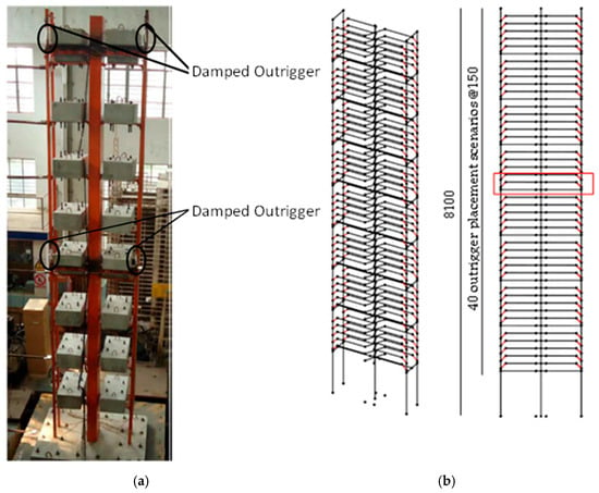
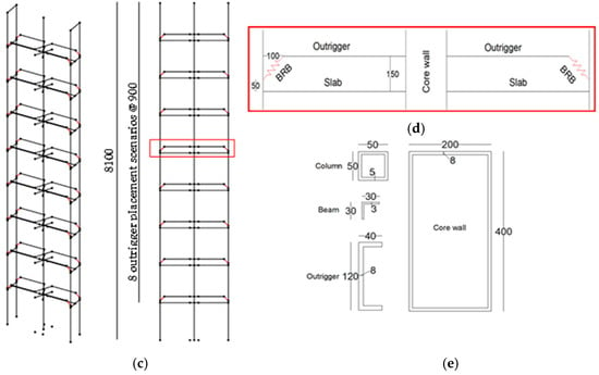
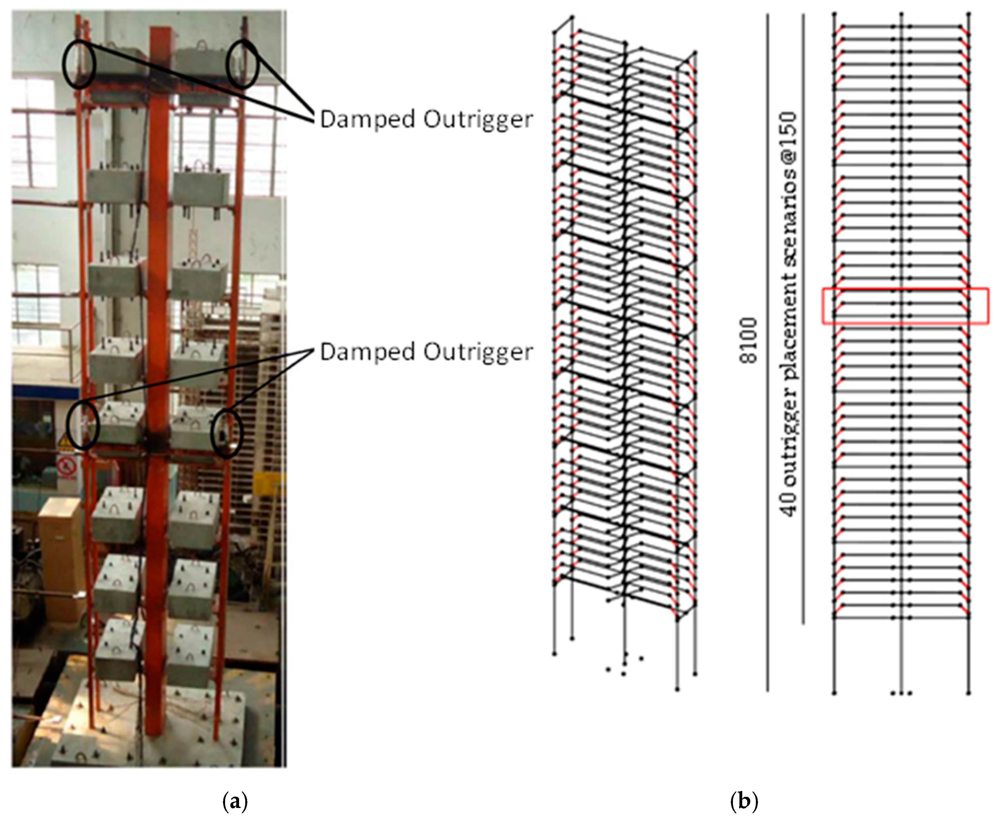
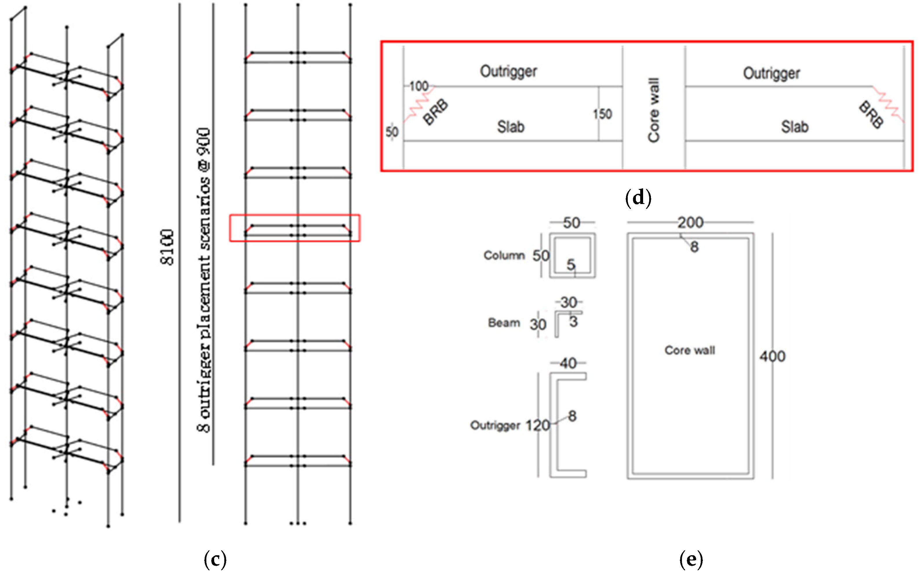
The structural model employed in this study is derived from the prototype used in the shaking table experiments reported in [25]. The model has dimensions of 1600 mm by 400 mm in each horizontal direction and is constructed using steel with a nominal yield strength of 345 MPa. A core wall measuring 200 mm by 400 mm features an 8 mm thick steel tube. The columns have dimensions of 50 mm by 50 mm with a 5 mm thickness. In the Y-direction, each zone is connected to the column using two L-section steel beams measuring 30 mm by 30 mm with a 3 mm thickness. The outriggers are constructed from steel channels with a cross-section of 120 mm by 40 mm and an 8 mm thickness. An additional mass of 280 kg is added to each story. The original model shown in Figure 1a includes two outriggers with attached VD located at zones 4 and 8, representing damped outriggers.
Figure 1.
Schematic image of target model, (a) original model on shaking table test [25], (b) model with variable heights of outrigger–BRBs, (c) model with fixed heights of outrigger–BRBs (d) details of outrigger–BRB configurations, (e) sectional sizes of structural member. (units: mm).
In this study, the overall height of the structure is set to 8100 mm and discretized into a nine-zone model. Each zone has a uniform height of 900 mm, as illustrated in Figure 1b,c. Outriggers are permitted in zones 2 through 9, and BRBs are installed at each outrigger level to represent damped outrigger–BRB systems.
Two similar optimization strategies are evaluated using the same Finite Element FE model but with different outrigger configurations as illustrated in Table 1. In the first strategy, eight discrete outrigger–BRB location scenarios are considered. In the second strategy, a total of 40 potential outrigger–BRB levels are defined within zones 2 to 9, as shown in Figure 1b. Each zone is subdivided into five possible outrigger levels; each located 150 mm above the floor level. For the optimization process, each zone is constrained to contain a maximum of one outrigger–BRB selected from the five available locations. In this configuration, outriggers are installed at a fixed elevation of 150 mm above the floor levels, rigidly connected to the core wall and linked to the perimeter columns through BRBs. A 100 mm clearance is provided between the outriggers and the columns to accommodate the BRBs. The BRBs are installed between the outrigger and the column, with the i-end connected to the outrigger at the outrigger level and the j-end connected to the column at a point 50 mm above the floor level, as shown in Figure 1d.
Table 1.
Overview of fixed and variable height outrigger–BRB configurations.
3. Optimization Formulation
This study addresses the optimal allocation of a prescribed total stiffness of BRB along the height of a core-wall-dominated structural model to minimize its seismic response. The optimization variables are the vertical locations of outrigger–BRB and the BRB stiffness assigned to each location, while the objective function is defined as the minimization of the maximum inter-story drift under seismic excitation, subject to a constraint on the total available BRB stiffness.
A power-based optimization algorithm is implemented in MATLAB, in which the total BRB stiffness is incrementally distributed starting from zero. At each optimization step, a predefined stiffness increment ∆k is temporarily assigned to one eligible story (and outrigger level, where applicable), while previously selected configurations are retained. Nonlinear time-history analysis is performed for the resulting candidate models, and the configuration yielding the minimum objective function value is selected. This sequential allocation process is repeated until the prescribed total BRB stiffness is reached.
At each optimization step, the number of candidate models evaluated is equal to the number of eligible installation locations, resulting in a total number of nonlinear analysis that scales linear with the size of the candidate set. This contrasts with the combinatorial growth associated with exhaustive or evolutionary optimization methods and leads to a significant reduction in computational efforts. The stiffness increment ∆k was selected to balance resolution and efficiency, and sensitivity studies confirmed that further reductions in ∆k did not materially alter the identified optimal zones, indicating robust optimization outcomes. The proposed approach follows a greedy allocation strategy and is intended as a computationally efficient framework for preliminary design and comparative assessment rather than a guarantee of global optimality.
3.1. Optimization Procedure of Outrigger–BRBs with Fixed-Height
The optimization formulation of fixed height outrigger–BRBs is illustrated in Figure 2 and Figure 3, and expressed mathematically by Equations (1)–(3) as follows:
where and indicate total BRB stiffness and BRB stiffness of i-th story, and indicates the maximum inter-story drift response of the i-th story.
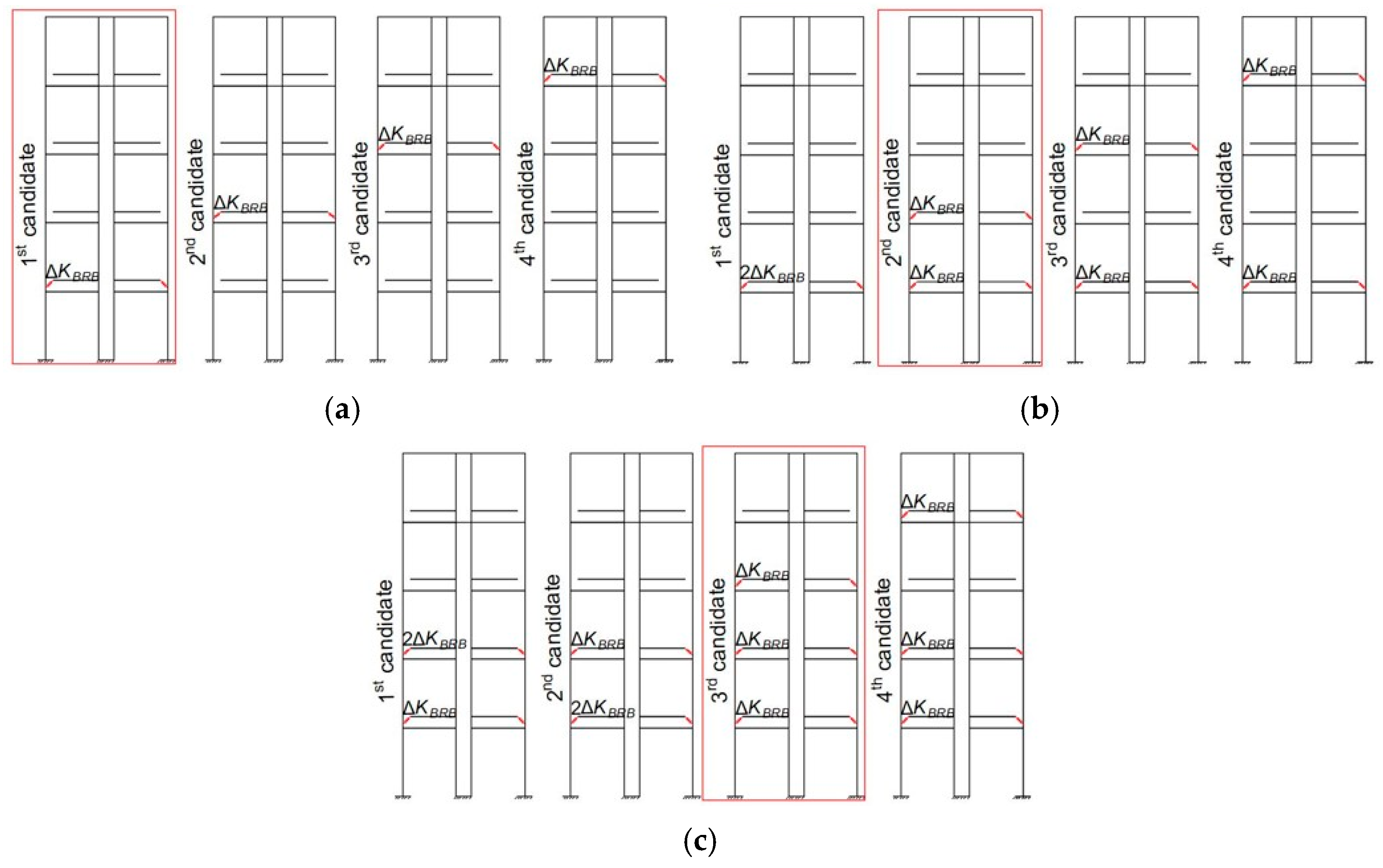
Figure 2.
Schematic model of outrigger–BRB placement with fixed height, (a) 1st step, 1st candidate is selected, (b) 2nd step, 2nd candidate is selected, (c) 3rd step, 3rd candidate is selected.
Figure 3.
Optimization flowchart of outrigger–BRBs configuration with variable heights.
Figure 2 conceptually illustrates the sequential allocation of BRB stiffness across the building height. Although only four candidate models are shown for clarity, a total of eight candidate solutions is considered for the nine-zone model, consistent with the number of zones eligible for outrigger–BRB installation.
In the initial optimization step, candidate models are generated by assigning incremental stiffness Δk to different stories. The candidate exhibiting the lowest inter-story drift response is selected as the optimal configuration, as illustrated in Figure 2a. The identified optimal story is then fixed, and in the subsequent step an additional stiffness increment Δk is assigned to the remaining stories. The second optimal story is determined based on the minimum inter-story drift response, as shown in Figure 2b. This sequential allocation process continues iteratively until the final stiffness distribution is achieved, as illustrated in Figure 2c. The optimization workflow is further summarized in the flowchart shown in Figure 3.
3.2. Optimization Procedure of Outrigger–BRBs with Variable-Height
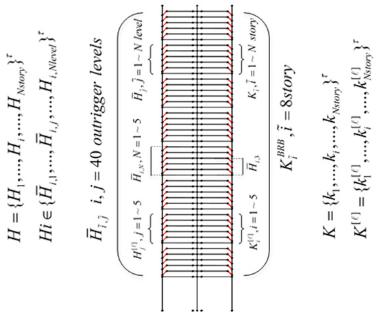
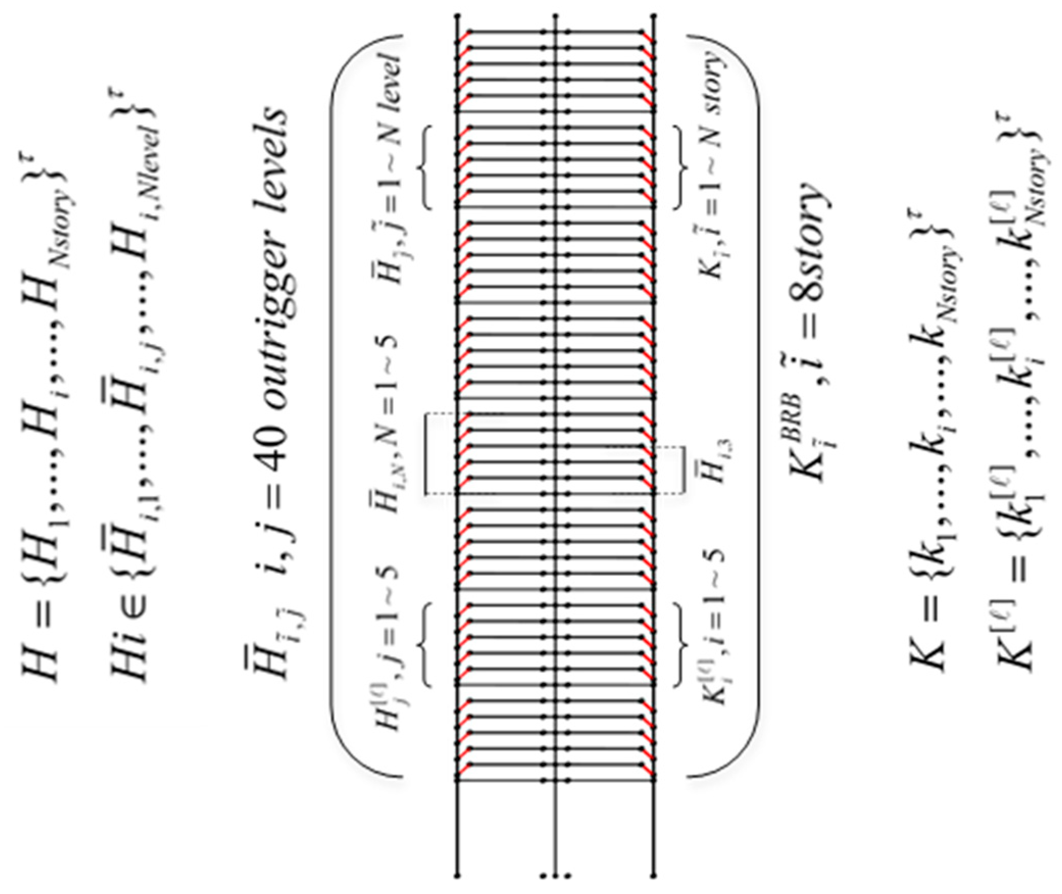
Figure 4 illustrates the configuration of the outrigger–BRB system with variable installation heights considered in this study. In contrast to the fixed-height formulation described in the previous section, the proposed approach extends the optimization framework to simultaneously determine (a) the optimal outrigger installation level within each story, (b) the optimal distribution of BRB stiffness, and (c) the corresponding story locations along the building height. This formulation allows a more flexible representation of practical outrigger placement constraints and significantly expands the search space explored by the optimization algorithm.
Figure 4.
Schematic representation of the discretized building height and candidate outrigger–BRB installation with variable heights.
The building height is discretized into a finite set of admissible story elevations, denoted by
where represents the elevation of the -th story measured from the first story, and is the total number of stories where outrigger–BRBs are to be installed. As illustrated in Figure 4, each element corresponds to a potential installation location for the outrigger–BRB system.
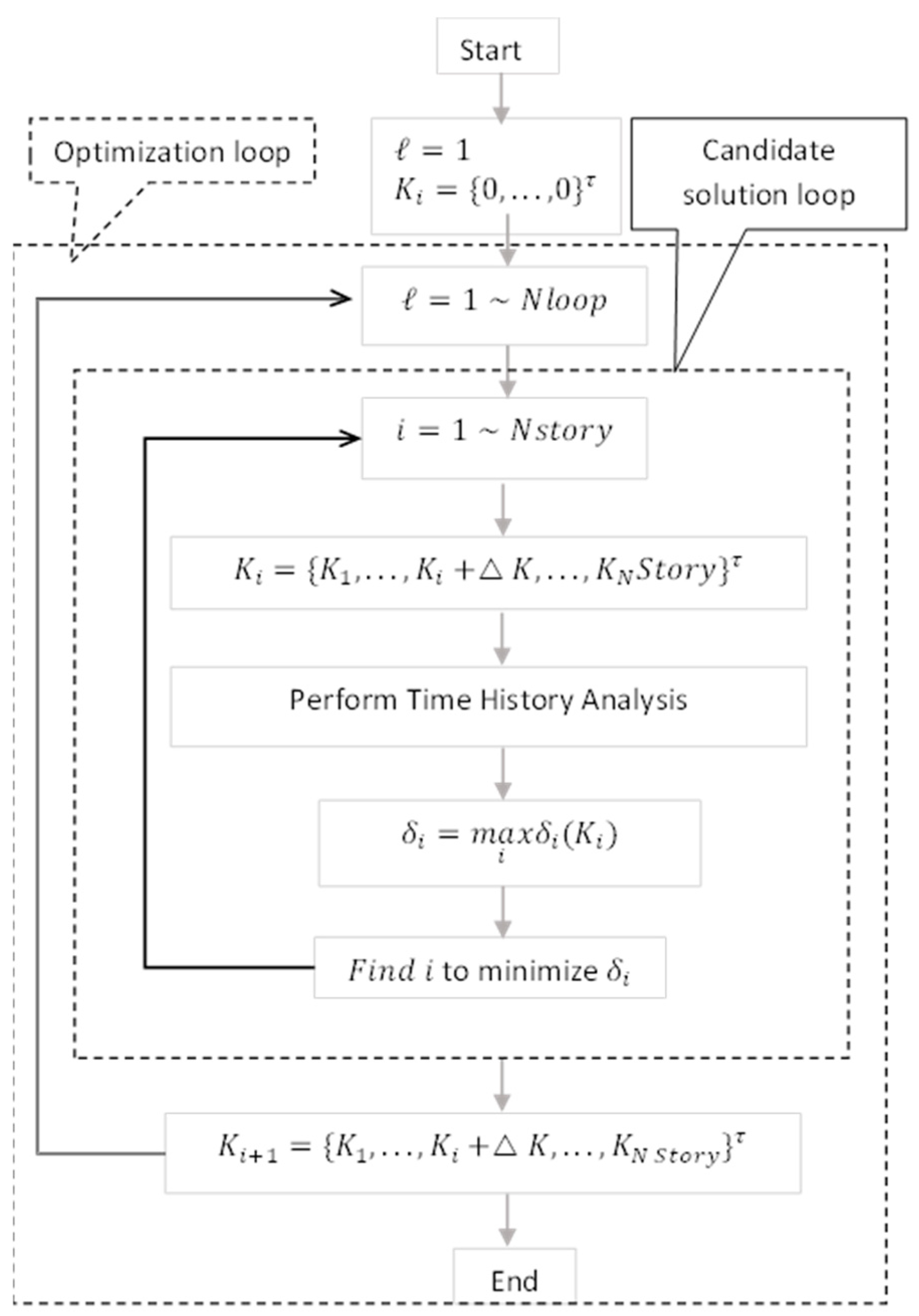
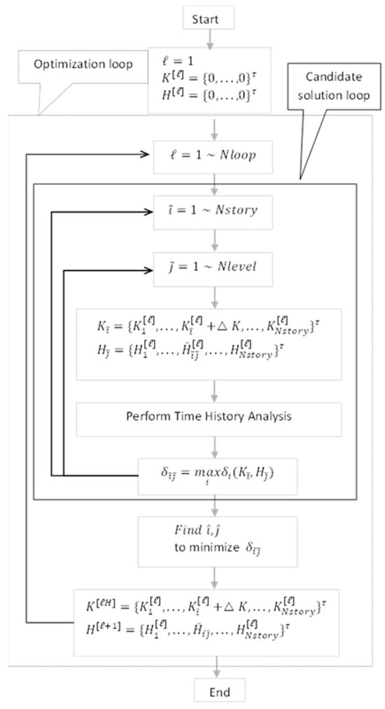
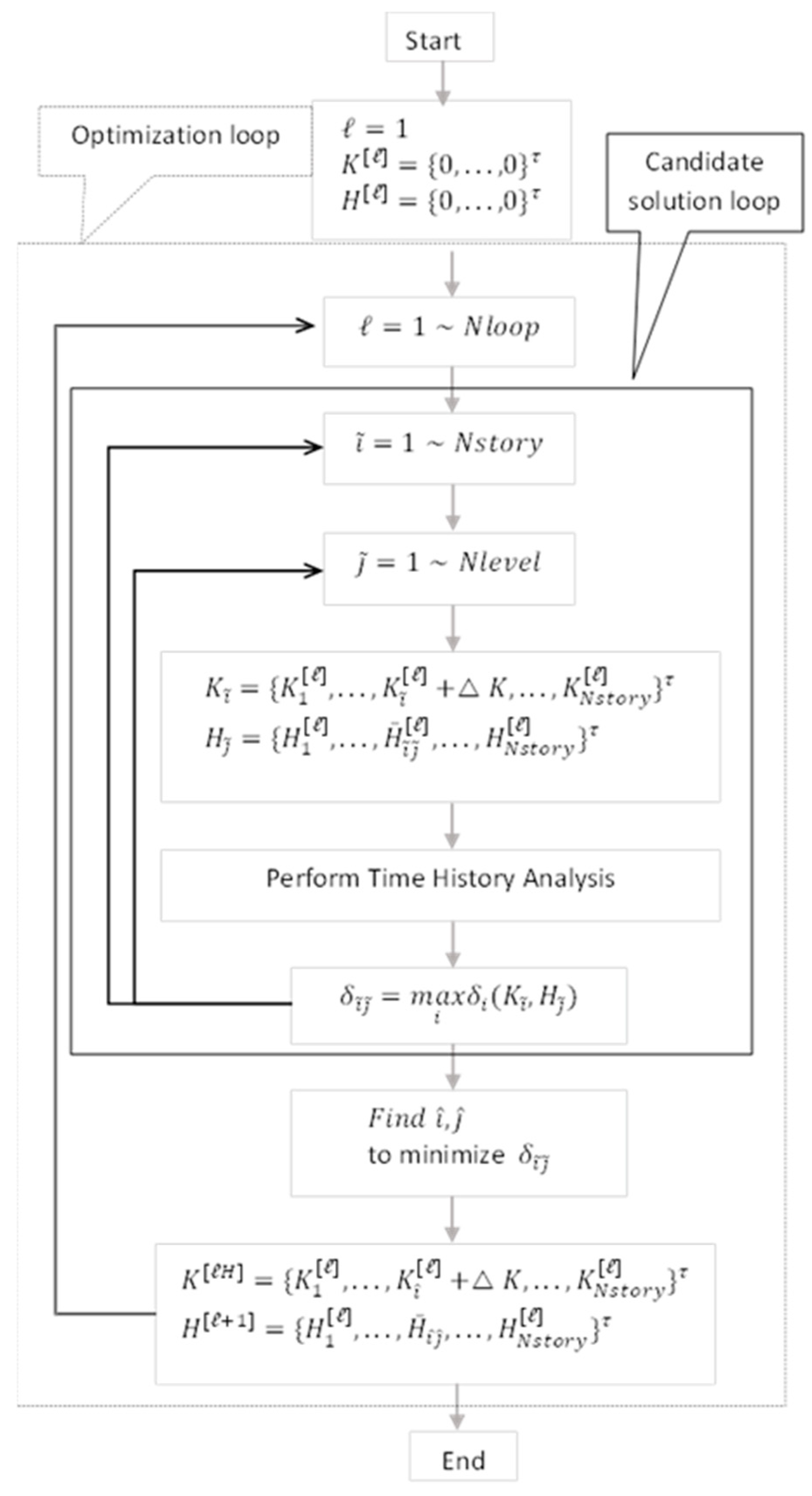
To facilitate interpretation of Figure 4 and Figure 5, the notation used in this section is defined as follows. The index denotes the optimization loop number. The indices and represent the story number and the outrigger level within a given story, respectively. The variable denotes the BRB stiffness assigned to the -th story, while represents the height of the -th outrigger level measured from the corresponding floor level. The term denotes the effective global height of the outrigger–BRB system associated with the -th story. The seismic response quantity represents the maximum inter-story drift response corresponding to the -th outrigger level with BRB stiffness at the -th optimization loop.
Figure 5.
Optimization flowchart of outrigger–BRBs configuration with variable heights.
As shown in Figure 5, the proposed optimization procedure consists of two nested loops: a candidate solution loop and an optimization loop. The optimization process begins with the candidate solution loop, in which outriggers are initially installed at all designated stories. For each story, multiple discrete outrigger levels are predefined, and BRBs are temporarily assigned to each level to generate candidate configurations.
For each candidate structural model, nonlinear time-history analysis is performed, and the corresponding maximum inter-story drift response is computed. The candidate configuration yielding the minimum inter-story drift response is identified as the optimal solution for that optimization step.
In the present study, a total of 40 candidate solutions are considered, corresponding to five potential outrigger levels within each of the eight eligible stories. Accordingly, five candidate configurations are evaluated during each iteration of the candidate solution loop. Once the optimal story and outrigger level are identified, the selected configuration is retained, and the optimization loop proceeds to the next iteration by increasing the total BRB stiffness. This process is repeated until the prescribed total BRB stiffness is reached. Through this iterative procedure, the proposed method systematically identifies the optimal number, story location, and vertical placement of outrigger–BRBs based on the minimization of inter-story drift response.
4. Results
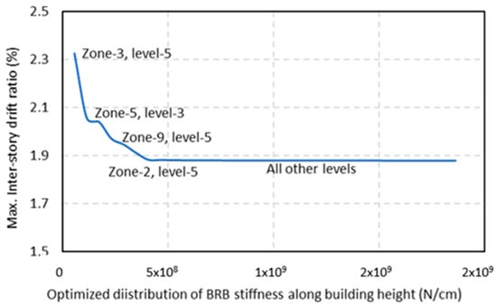
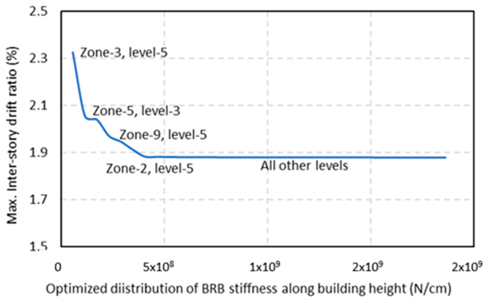
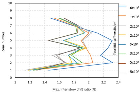
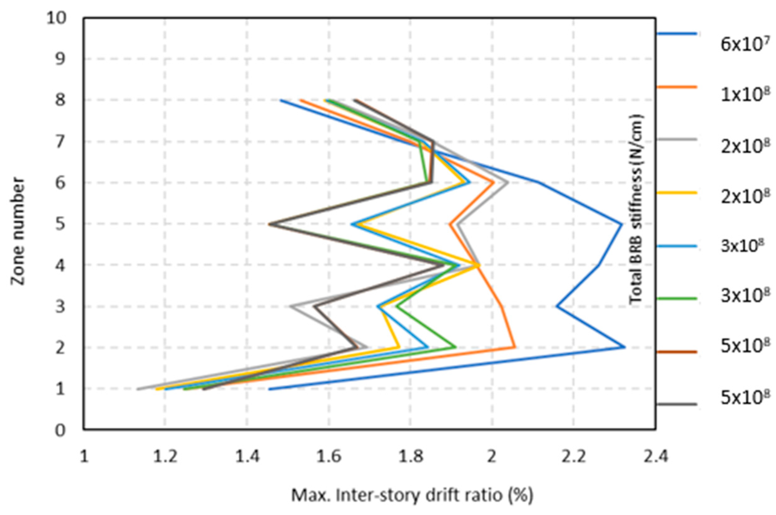
The results of the proposed optimization procedure are presented in Figure 6, Figure 7, Figure 8, Figure 9 and Figure 10. The primary objective of this study is to determine the optimal distribution of BRBs at each outrigger connection zone and to investigate the influence of BRB stiffness on optimal outrigger placement and overall seismic performance.
Figure 6.
Optimal solution of outrigger–BRBs configuration with variable heights.
Figure 7.
Inter-story drift response of model at each optimization step for outrigger–BRBs configuration with variable heights.
Figure 8.
Optimal solution of outrigger–BRBs configuration with fixed heights.
Figure 9.
Inter-story drift response of model at each optimization step for outrigger–BRBs configuration with fixed heights.
Figure 10.
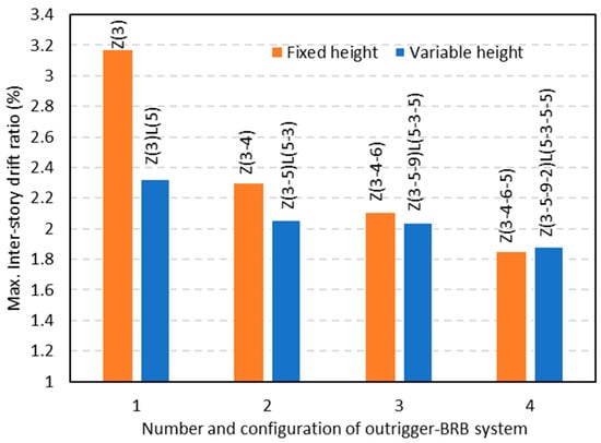
Comparison of optimal placement of outrigger–BRBs configuration with variable and fixed heights.
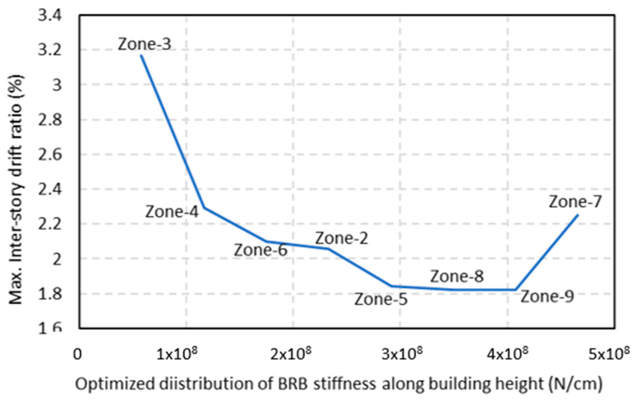
Figure 6 illustrates the results of the optimization steps for the variable-height configuration. The results indicate that outrigger–BRBs installed in zones 3, 5, 9, and 2 at outrigger levels 5, 3, 5, and 5, respectively, provide the most effective reduction in inter-story drift response. These zones are therefore identified as the optimal locations for outrigger–BRB installation in the variable-height model. In contrast, the remaining optimization steps corresponding to zones 4, 6, 7, and 8 do not result in noticeable improvement in structural response.
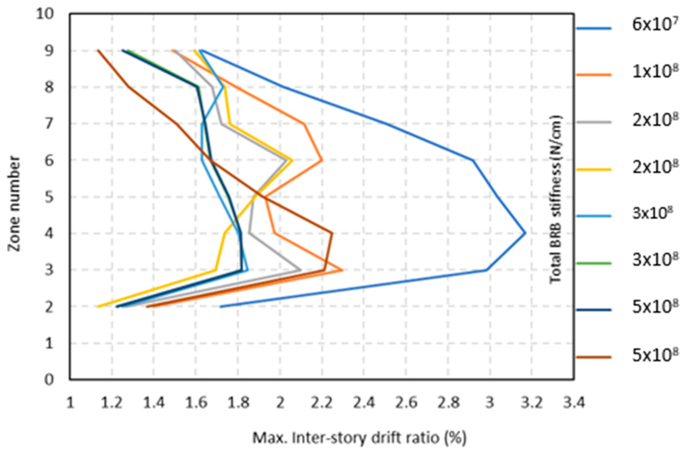
Figure 7 presents the evolution of inter-story drift response at successive optimization steps for the variable-height configuration. Although a total of 40 optimization steps is associated with all possible outrigger-level combinations, only representative steps are shown for clarity. The legend values represent the cumulative BRB stiffness allocated at each optimization step (N/cm).
The optimal outrigger–BRB configuration for the fixed-height model is shown in Figure 8. For this configuration, zones 3, 4, 6, and 5 are identified as the most effective locations. Installations in zones 2, 8, and 9 exhibit minimal influence, while placement in zone 7 leads to a slight increase in inter-story drift response. Figure 9 illustrates the variation in inter-story drift response at each optimization step for the fixed-height configuration as a function of total BRB stiffness distribution.
A comparative assessment of both strategies is presented in Figure 10. For configurations involving one, two, and three outrigger–BRBs, the variable-height approach consistently achieves lower inter-story drift responses than the fixed-height configuration. When four outrigger–BRBs are installed, both strategies converge to nearly identical performance levels. Both approaches consistently identify zone 3 as the optimal location for a single outrigger–BRB. For the variable-height configuration, the optimal outrigger–BRB installation heights correspond to height ratios of 0.2037 H, 0.3148 H, 0.5 H, and 0.981 H, whereas the fixed-height configuration yielded optimal height ratios of 0.2407 H, 0.3518 H, 0.463H, and 0.574 H.
Table 2 summarizes the distribution of stiffness allocation increments Δk across the outrigger connection zones for both optimization strategies. For the variable-height configuration, stiffness allocation is concentrated primarily in zones 3, 5, and 2, with the highest number of increments assigned to zone 3. In contrast, the fixed-height configuration exhibits a uniform distribution, with one stiffness increment assigned to each eligible zone.
Table 2.
Number of stiffness allocation increments (Δk) at each outrigger connection zone/level. “–” indicates that no (Δk) is allocated at the corresponding zone/level.
5. Discussion
This study proposed a power-based optimization framework to determine the optimal number and vertical placement of outrigger–BRB systems for improving seismic performance. The optimization objective was defined as the minimization of peak inter-story drift under a prescribed total BRB stiffness constraint.
Two optimization strategies were investigated: fixed-height and variable-height outrigger–BRB placement. The results demonstrate that only a subset of installation zones contributes meaningfully to seismic response reduction. For the fixed-height configuration, zones 3, 4, 6, and 5 were found to be optimal, with certain zones producing minimal or adverse effects. For the variable-height configuration, zones 3, 5, 9, and 2 were identified as most effective, whereas additional BRB installations in other zones yielded negligible improvements.
These observations can be interpreted in the context of core–perimeter interaction mechanics. Outrigger effectiveness depends on the relative rotation and lateral deformation between the core wall and perimeter columns. At elevations where differential deformation is significant, outrigger–BRB systems mobilize higher axial forces, resulting in greater restraint of core rotation and reduced inter-story drift.
The comparative analysis indicates that allowing vertical flexibility in outrigger placement enhances performance for low-to-moderate numbers of outriggers. However, as the number of installed outriggers increases, the performance difference between fixed and variable height strategies diminishes.
Several limitations should be noted. The optimization framework was demonstrated using a scaled nine-zone benchmark model subjected to a single earthquake record (1940 El Centro). Consequently, the identified optimal configurations are influenced by the selected ground-motion characteristics and model configuration. The results should therefore be interpreted as applicable to the benchmark investigated system rather than as universal design recommendations.
Furthermore, the optimization objective was limited to peak inter-story drift response. While drift is a primary indicator of seismic damage, other response metrics including floor accelerations, base shear, internal force demands, and BRB ductility were not explicitly evaluated. Multi-objective optimization incorporating these performance measures is recommended for future research. The scaled benchmark model captures key deformation characteristics of core-dominated systems but does not explicitly account for scaling laws, higher-mode effects, P–Δ behavior, or torsional response. Extension to full-scale high-rise archetypes remains a topic for future investigation.
6. Conclusions
This study presented a power-based optimization framework for determining the optimal number and vertical placement of outrigger–BRB systems in core-wall-dominated structures. The proposed algorithm incrementally allocates BRB stiffness and identifies optimal configurations based on nonlinear time-history drift response while maintaining computational efficiency. The results indicate that only a limited number of outrigger locations contribute significantly to seismic performance improvement. For the investigated nine-zone benchmark model, the optimal number of outrigger–BRBs required to achieve minimum inter-story drift was found to be four for both variable- and fixed-height configurations.
The variable-height strategy provided superior performance for configurations involving one to three outriggers, demonstrating the benefit of vertical placement flexibility. However, both approaches converged to similar performance when four outriggers were installed. The proposed framework offers an efficient preliminary design tool for evaluating outrigger–BRB placement strategies and identifying effective stiffness distributions with reduced computational demand. Future work will extend the methodology to multiple ground-motion records, alternative structural archetypes, and multi-objective performance criteria.
Author Contributions
H.N.: Writing—original draft preparation, conceptualization, methodology and visualization, analysis, investigation, data curation; S.Y.: Supervision, review and software development and validation. All authors have read and agreed to the published version of the manuscript.
Funding
This work was supported by JST SPRING, Grant Number JPMJSP2101.
Data Availability Statement
The data presented in this study are available in the article.
Acknowledgments
During the preparation of this manuscript, the author(s) used Grammarly and ChatGPT 5.2 for the purpose of revising the text editing and grammar refinement. The authors have reviewed and edited the output and take full responsibility for the content of this publication.
Conflicts of Interest
The authors declare no conflicts of interest.
Abbreviations
The following abbreviations are used in this manuscript:
| BRB | Buckling Restrained Brace |
| RSA | Response Spectrum Analysis |
| NRHA | Nonlinear Response History Analysis |
| LVD | Viscous Damper |
| FE | Finite Element |
| FVD | Fluid Viscous Damper |
References
- Stafford Smith, B.B.; Salim, I. Parameter study of outrigger-braced tall building structures. J. Struct. Div. ASCE 1981, 107, 2001–2014. [Google Scholar] [CrossRef] [Scilit]
- Sun, F.F.; Yang, G.; Hu, Z.B. A single-step seismic optimal design method for damped outrigger structures with buckling-restrained braces. Eng. Struct. 2021, 249, 113262. [Google Scholar] [CrossRef] [Scilit]
- Smith, R.J.; Willford, M.R. The damped outrigger concept for tall buildings. Struct. Des. Tall Spec. Build. 2007, 16, 501–517. [Google Scholar] [CrossRef] [Scilit]
- Huang, B.; Takeuchi, T. Dynamic response evaluation of damped-outrigger systems with various heights. Earthq. Spectra 2017, 33, 665–685. [Google Scholar] [CrossRef] [Scilit]
- Chen, Y.; McFarland, D.M.; Wang, Z.; Spencer, B.F.; Bergman, L.A. Analysis of tall buildings with damped outriggers. J. Struct. Eng. 2010, 136, 1435–1443. [Google Scholar] [CrossRef] [Scilit]
- Tan, P.; Fang, C.; Zhou, F. Dynamic characteristics of a novel damped outrigger system. Earthq. Eng. Eng. Vib. 2014, 13, 293–304. [Google Scholar] [CrossRef] [Scilit]
- Kavyashree, B.G.; Patil, S.; Rao, V.S. Evolution of outrigger structural systems: A state-of-the-art review. Arab. J. Sci. Eng. 2021, 46, 10313–10331. [Google Scholar] [CrossRef] [Scilit]
- Viise, J.; Ragan, P.; Swanson, J. BRB and FVD alternatives to conventional steel brace outriggers. In Proceedings of the CTBUH 2014 Shanghai Conference, Shanghai, China, 16–19 September 2014; pp. 691–699. [Google Scholar]
- Asai, T.; Terazawa, Y.; Miyazaki, T.; Lin, P.C.; Takeuchi, T. First-mode damping-ratio-oriented optimal design procedure for damped outrigger systems with additional linear viscous dampers. Eng. Struct. 2021, 247, 113229. [Google Scholar] [CrossRef] [Scilit]
- Lin, P.C.; Tsai, S.J. Seismic performance and design of damped-outrigger systems incorporating buckling-restrained braces for buildings with various heights. Structures 2022, 44, 1565–1582. [Google Scholar] [CrossRef] [Scilit]
- Lin, P.C.; Takeuchi, T.; Matsui, R. Seismic performance evaluation of single damped-outrigger systems incorporating buckling-restrained braces. Earthq. Eng. Struct. Dyn. 2018, 47, 2343–2365. [Google Scholar] [CrossRef] [Scilit]
- Lin, P.C.; Takeuchi, T.; Matsui, R. Optimal design of multiple damped-outrigger systems incorporating buckling-restrained braces. Eng. Struct. 2019, 194, 441–457. [Google Scholar] [CrossRef] [Scilit]
- Baygi, S.; Khazaee, A. The optimal number of outriggers in a structure under different lateral loadings. J. Inst. Eng. (India) Ser. A 2019, 100, 753–761. [Google Scholar] [CrossRef] [Scilit]
- Zhou, Y.; Zhang, C.; Lu, X. Seismic performance of a damping outrigger system for tall buildings. Struct. Control Health Monit. 2017, 24, e1864. [Google Scholar] [CrossRef] [Scilit]
- Tavakoli, R.; Kamgar, R.; Rahgozar, R. Optimal location of energy dissipation outriggers in high-rise buildings considering nonlinear soil–structure interaction effects. Period. Polytech. Civ. Eng. 2020, 64, 887–903. [Google Scholar] [CrossRef] [Scilit]
- Wang, M.; Nagarajaiah, S.; Sun, F.F. Dynamic characteristics and responses of damped outrigger tall buildings using negative stiffness. J. Struct. Eng. 2020, 146, 04020273. [Google Scholar] [CrossRef] [Scilit]
- Chen, Y.; Zhang, Z. Analysis of outrigger numbers and locations in outrigger-braced structures using a multi-objective genetic algorithm. Struct. Des. Tall Spec. Build. 2018, 27, e1408. [Google Scholar] [CrossRef] [Scilit]
- Xing, L.; Zhou, Y.; Aguaguiña, M. Optimal vertical configuration of combined energy dissipation outriggers. Struct. Des. Tall Spec. Build. 2019, 28, e1579. [Google Scholar] [CrossRef] [Scilit]
- Wang, L.; Zhao, X. Fast optimization of outriggers for super-tall buildings using a sensitivity vector algorithm. J. Build. Eng. 2021, 43, 102531. [Google Scholar] [CrossRef] [Scilit]
- Morales-Beltran, M.; Turan, G.; Dursun, O.; Nijsse, R. Energy dissipation and performance assessment of double damped outriggers in tall buildings under strong earthquakes. Struct. Des. Tall Spec. Build. 2019, 28, e1554. [Google Scholar] [CrossRef] [Scilit]
- Zhou, Y.; Zhang, C.; Lu, X. An inter-story drift-based parameter analysis of the optimal location of outriggers in tall buildings. Struct. Des. Tall Spec. Build. 2016, 25, 215–231. [Google Scholar] [CrossRef] [Scilit]
- İnam, İ.E.; Çeribaşı, S.; Karapınar, I.S. Determining the optimum outrigger locations for steel tall buildings by using time-history analyses. Struct. Des. Tall Spec. Build. 2021, 30, e1843. [Google Scholar] [CrossRef] [Scilit]
- Nikzad, H.; Yoshitomi, S. Application of power algorithm optimization for optimal placement of buckling-restrained braces in a 3D shear wall–frame building structure. IOP Conf. Ser. Earth Environ. Sci. 2023, 1196, 012061. [Google Scholar] [CrossRef] [Scilit]
- Nikzad, H.; Yoshitomi, S. Optimal placement method of outrigger with buckling-restrained braces in a core wall system structure. In Proceedings of the 9th International Conference on Computational Methods in Structural Dynamics and Earthquake Engineering, Athens, Greece, 12–14 June 2023; pp. 4624–4631. [Google Scholar] [CrossRef] [Scilit]
- Tan, P.; Fang, C.J.; Tu, W.R.; Zhou, F.L.; Wang, Y.; Jiang, M. Experimental study on the outrigger damping system for high-rise building. In Proceedings of the 15th World Conference on Earthquake Engineering (WCEE), Lisbon, Portugal, 24–28 September 2012. Paper No. 2709. [Google Scholar]

Disclaimer/Publisher’s Note: The statements, opinions and data contained in all publications are solely those of the individual author(s) and contributor(s) and not of MDPI and/or the editor(s). MDPI and/or the editor(s) disclaim responsibility for any injury to people or property resulting from any ideas, methods, instructions or products referred to in the content. |
© 2026 by the authors. Licensee MDPI, Basel, Switzerland. This article is an open access article distributed under the terms and conditions of the Creative Commons Attribution (CC BY) license.