


Abstract
This study addresses the growing demand for efficient customization in industrial design by proposing a structured approach to automate Computer Aided Design (CAD) assembly generation and documentation. The objective is to reduce repetitive engineering effort while maintaining consistency and integration within existing digital environments. The methodology combines parametric modelling, configuration-driven design, and Visual Basic for Applications (VBA)-based scripting through CAD Application Programming Interfaces, supported by integration with a Product Lifecycle Management system. A structured data model and reorganised modular CAD architecture enable automated generation of assemblies, selection of configurations, and creation of technical drawings. The approach is validated through an industrial case study involving configurable mechanical assemblies, where performance is evaluated using a quantitative time-based framework. The results show a reduction in total configuration time from 8 to 16 h to approximately 2–3 h, corresponding to an average time saving of 79% and a significant decrease in effective engineering workload. Assessment of scalability indicates that engineering effort becomes largely independent of the number of configurations, while economic evaluation indicates strong return-on-investment potential under typical industrial conditions. The findings confirm that systematic CAD automation can substantially improve productivity and consistency in configuration-driven design processes, provided that parametric models and data structures are properly standardised.
1. Introduction
Modern industrial production is increasingly influenced by the demand for customised products and rapid delivery times. Companies are expected to adapt their products to specific customer requirements while maintaining short development cycles and a high level of documentation quality [1,2,3]. These expectations place considerable pressure on engineering departments, where design tasks must be completed quickly, consistently, and with minimal risk of error.
Computer-aided design systems provide a wide range of tools intended to support this process. Parametric modelling enables engineers to define relationships between dimensions, constraints, and functional parameters so that model geometry can adapt automatically to changes in design inputs [4,5,6,7]. At the same time, contemporary CAD platforms offer Application Programming Interfaces that allow external scripts to interact with the modelling environment. Through such interfaces, it becomes possible to automate repetitive design activities, generate assemblies programmatically, and integrate CAD environments with enterprise information systems such as product lifecycle management platforms [8,9,10,11].
Despite these capabilities, a large portion of engineering work in many companies still consists of repetitive manual activities. Engineers often create assemblies from predefined components, manually select configurations, modify parameters, and prepare drawing documentation for each individual order. When the number of product variants increases, these tasks become time-consuming and susceptible to human error. Furthermore, manual procedures limit scalability and introduce inconsistencies in documentation [12,13,14].
Although various studies discuss CAD automation and knowledge-based engineering approaches, practical implementations frequently remain tailored to specific use cases. Many solutions focus on particular product families and do not provide a structured methodology that could be reused in other contexts [15,16,17,18]. In addition, quantitative evidence demonstrating the real benefits of automation in industrial environments is relatively scarce [19,20].
This paper therefore presents a methodology for automating customized CAD assembly generation and drawing documentation using VBA scripting and CAD Application Programming Interfaces. The approach combines parametric modelling principles, structured configuration logic, and integration with PLM systems. A real industrial case study is used to evaluate the effectiveness of the method and to quantify its impact on engineering efficiency.
The contribution of this work lies not only in demonstrating a working automation solution but also in formulating a general framework for CAD automation that can be transferred to other engineering environments dealing with configurable products.
2. Background and Related Work
The increasing demand for product customization and shorter development cycles has significantly influenced modern engineering design practices [1,2,3]. Computer-aided design (CAD) systems have become a central tool in mechanical engineering, enabling the creation, modification, and documentation of complex products within digital environments [21,22,23]. Over the past decades, research has focused on extending the capabilities of CAD systems through parametric modelling, design automation, and integration with enterprise information systems [12,19,24].
2.1. Parametric Modelling in Mechanical Design
Parametric modelling represents one of the fundamental paradigms of modern CAD systems. In parametric design, geometric entities are defined through parameters, constraints, and relationships, enabling the model geometry to update automatically in response to changes in design variables [4,5,6,7]. This approach allows engineers to develop flexible and adaptable models capable of representing multiple product variants within a single parametric structure.
Parametric modelling is particularly valuable in environments where products must be frequently adapted to customer-specific requirements. By defining relationships between dimensions and features, engineers can efficiently generate alternative configurations without rebuilding the entire model from scratch. Such flexibility significantly reduces modelling effort and helps maintain consistency across product families [24,25].
In addition to improving design flexibility, parametric modelling also supports integration with optimization and simulation workflows. By linking parameter changes to analysis models, automated updates of simulation results become possible, enabling iterative design improvements and more efficient engineering processes [26,27,28,29,30,31].
2.2. Design Automation and Knowledge-Based Engineering
While parametric modelling provides the structural basis for flexible design models, the concept of design automation aims to reduce manual engineering effort by automatically generating design solutions based on predefined rules and knowledge [12,19].
One widely studied approach in this context is Knowledge-Based Engineering (KBE). KBE systems capture engineering knowledge in the form of rules, constraints, and procedures that can be reused across multiple design tasks [32,33,34,35]. By formalizing expert knowledge and embedding it into digital tools, KBE systems can automatically generate product variants, assist with design decisions, and reduce the time required for repetitive modelling tasks.
The primary advantage of KBE lies in its ability to transform engineering expertise into reusable digital assets. Once design rules and dependencies are defined, the system can automatically construct models or assemblies that satisfy specified requirements. This capability is particularly useful in industries producing configurable products, where similar design tasks are repeated across multiple customer orders [15,33].
Despite its advantages, full-scale implementation of KBE systems often requires significant development effort and organizational change. As a result, many companies adopt intermediate approaches that combine parametric modelling with scripting or macro-based automation rather than implementing complete KBE frameworks [16,34,36,37].
2.3. CAD Automation Using Application Programming Interfaces
Modern CAD platforms provide Application Programming Interfaces (APIs) that allow external programs or scripts to control modelling operations programmatically. These APIs enable developers to automate tasks such as creating parts, generating assemblies, modifying parameters, and producing drawing documentation directly from external applications [8,9,10,11].
Automation through CAD APIs has become an increasingly important research and industrial topic. By integrating CAD software with programming environments, engineers can build custom tools that streamline repetitive modelling tasks and improve data consistency. Several studies demonstrate that combining parametric modelling with scripting languages or VBA macros can significantly accelerate the generation of CAD models and reduce the risk of manual errors [38,39,40].
In industrial practice, API-based automation is often used to connect CAD systems with external data sources such as spreadsheets, configuration databases, or enterprise information systems. These integrations allow engineering data to drive the generation of design models directly, creating a more consistent and scalable digital workflow [30,31,41].
2.4. Integration with Product Lifecycle Management Systems
Product Lifecycle Management (PLM) systems provide a structured environment for managing product data throughout the entire lifecycle, from early design stages to manufacturing, maintenance, and eventual product retirement [1,42,43,44]. Integration between CAD tools and PLM platforms plays a crucial role in maintaining data consistency and traceability across engineering processes.
Research has shown that PLM systems can serve as a foundation for automated design workflows by providing a central repository for design objects, configuration data, and metadata [45,46,47,48]. Leveraging PLM architectures enables object reuse, distributed data management, and automated execution of engineering processes across multiple system components.
However, many PLM environments are not inherently designed for advanced design automation and often require custom extensions or API-based solutions to support automated workflows. Consequently, practical implementations frequently involve hybrid architectures combining parametric CAD models, automation scripts, and PLM database connectivity [3].
2.5. Research Gap
Although the literature demonstrates substantial progress in parametric modelling, knowledge-based engineering, and CAD automation, published studies often address specific product families, individual engineering tasks, or experimental prototypes rather than fully integrated industrial applications [16,19]. This limited scope does not necessarily reflect the extent of industrial adoption. Similar solutions are used in various forms by companies working with highly configurable products and repetitive engineering processes, but their implementation details and results are rarely disclosed. Such information may involve proprietary methods, internal know-how, intellectual property, and commercially sensitive performance or economic data. As a result, a gap remains between the practical use of CAD automation in industry and the amount of corresponding evidence available in the scientific literature.
Quantitative evaluations conducted in real industrial environments are particularly scarce. Although existing studies report improvements in modelling efficiency and automation capabilities, detailed assessments of engineering time savings, scalability, and economic impact are less common [20,36]. Publicly available research that combines such quantitative evaluation with the integration of CAD automation, CAD Application Programming Interfaces (APIs), and enterprise-level systems such as Product Lifecycle Management (PLM) platforms remains limited.
The present study addresses this gap by proposing a structured automation framework and evaluating its performance using quantitative data from an industrial case study. It therefore contributes both a transferable methodological approach to CAD automation and empirical evidence from its application in a real engineering environment.
3. Problem Definition and System Architecture
The problem addressed in this research originates from an industrial environment in which engineers repeatedly create customized product assemblies based on similar sets of input data. Although the company maintains a library of predefined components and subassemblies, the overall design process remains largely manual.
In the original workflow, customer requirements arrive in the form of technical specifications and configuration requests. These requirements must be reconciled with legislative constraints and internal company standards. The resulting information is processed in spreadsheet and document formats, typically using office software, and then handed over to a design engineer.
Based on these inputs, the engineer manually constructs the final assembly using predefined subassemblies stored in the company’s PLM database. The required components must be individually located, downloaded, and inserted into the CAD assembly structure. During this process, the engineer adapts certain parameters and introduces minor modifications reflecting the specific customer requirements. Once the 3D model is completed, the engineer prepares the necessary drawing documentation and uploads the results back into the PLM system.
Although the process relies on previously prepared data, it remains highly labor-intensive. In practice, the complete procedure typically requires between eight and sixteen hours of engineering work for a final assembly. The duration depends on the complexity of the assembly, the number of required adjustments, and the preparation of technical documentation.
From a system perspective, the process involves several interconnected elements: structured input data, a CAD modelling environment, a PLM data repository, and the engineer who manually coordinates the entire workflow. The absence of automated communication between these elements results in inefficiencies and unnecessary repetition of routine tasks [45,46,47,48].
The objective of this research is therefore to design an automated system capable of generating assemblies and documentation directly from structured input data while maintaining compatibility with the existing PLM infrastructure. The system architecture developed to address this objective consists of a Python (version 3.13) preprocessor, a CAD platform connected to a PLM database through an API layer and controlled by automation scripts written in VBA. Within this architecture, the automation script acts as the central coordinator that reads input parameters, constructs assemblies, generates documentation, and manages data exchange with the PLM system [8,9,10,11].
This architecture allows the previously fragmented process to be transformed into a structured digital workflow in which data, models, and documentation are handled in a consistent and automated manner.
4. Proposed Automation Methodology
The proposed methodology is based on the principle that effective automation requires not only programming but also appropriate structuring of engineering data and models. Before automation could be implemented, the existing product structures had to be reorganised so that they could be processed programmatically [16,19].
The first step involved the parametrisation of all relevant input data. Customer requirements, internal constraints, and configuration options were transformed into structured parameters that serve as the primary drivers of the generation process. These data are provided mainly through formatted Microsoft Office documents, including spreadsheets and technical forms. Since the documents follow formatting conventions but lack a rigid structure that would allow direct addressing of specific cells or text segments, a preprocessing layer was developed in Python using the openpyxl and python-docx libraries. This layer extracts, validates, and transforms the required information into a unified data structure suitable for subsequent automated processing while remaining robust to minor variations in document layout.
At the same time, the existing library of CAD models was reorganised. Predefined assemblies were remodelled so that their reference geometry corresponded to a predefined coordinate system. This step was essential because automated assembly generation requires predictable positioning of components. Without such consistency, automated placement of parts would not be reliable [13].
To increase modularity, configurations were introduced within assemblies. Instead of creating large numbers of individual models, multiple design variants were handled through parametrised configurations with structured naming conventions. This approach significantly reduced the total number of CAD files while preserving flexibility [24,34].
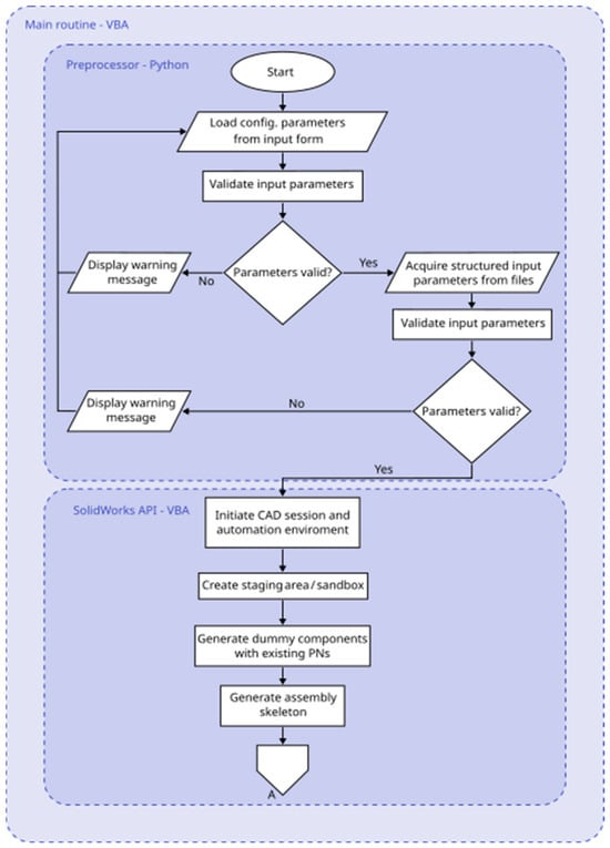
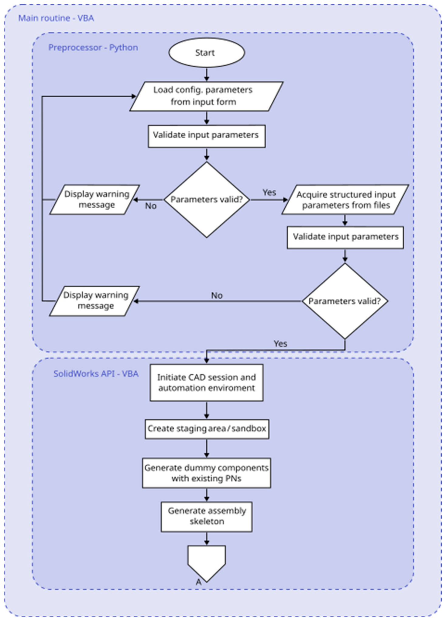
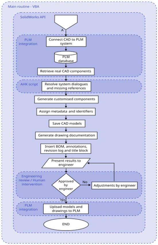
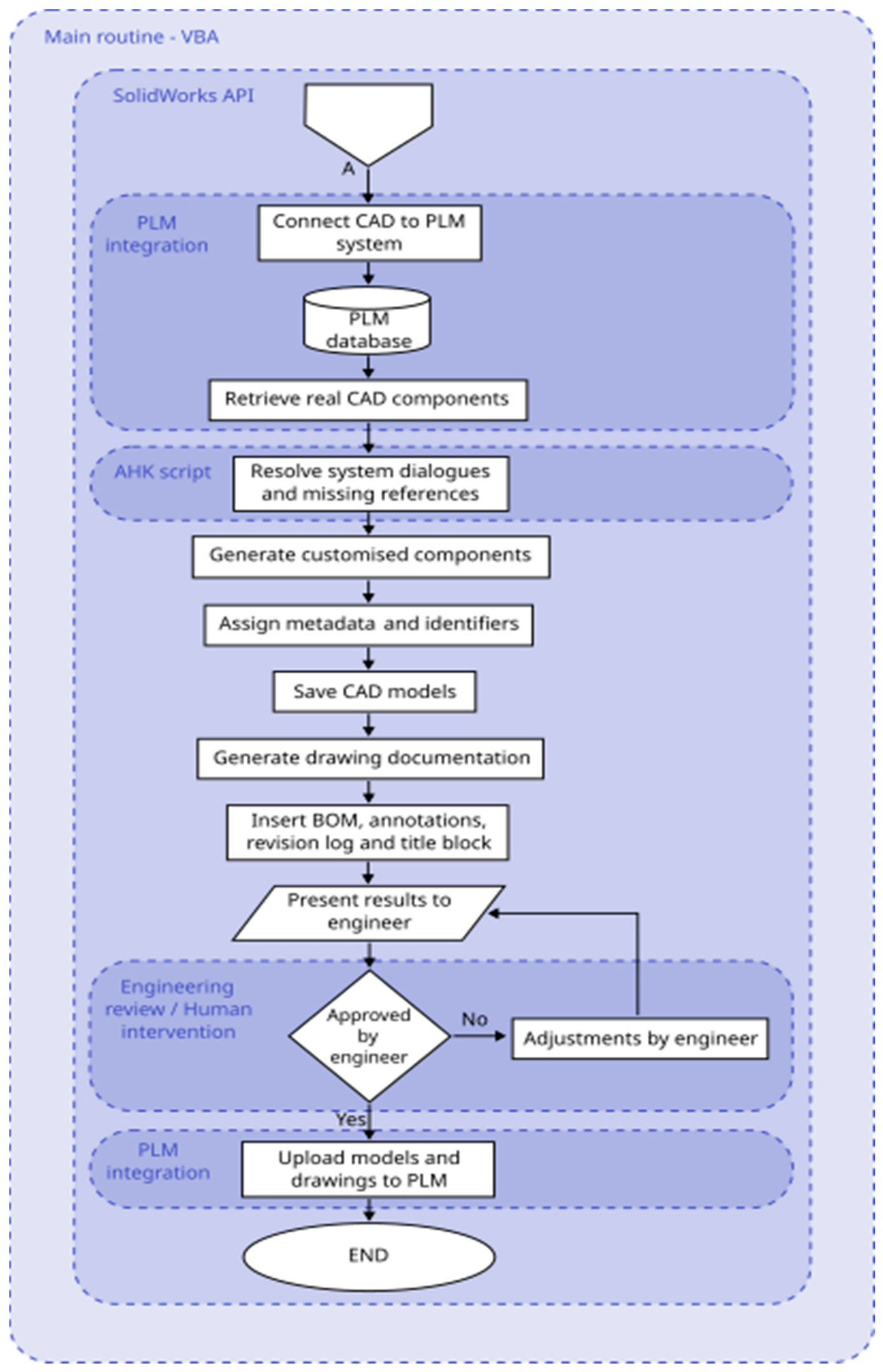
Once the parametric model structure was prepared, the automation logic was implemented using the CAD programming interface (API) and VBA. For visual representation of the automation logic see Figure 1 and Figure 2. The automated workflow begins when the engineer initiates the process by filling in a structured input form that specifies the desired configuration. The script reads the input data and prepares the modelling environment accordingly.
Figure 1.
Algorithm flowchart—Part 1: Initialization and input processing.
Figure 2.
Algorithm flowchart—Part 2: CAD–PLM integration and customization.
In the next phase, the system generates placeholder files in a staging area using existing part numbers from the PLM system. These placeholder files are used to construct a temporary assembly structure that represents the final product configuration. After the assembly structure has been created, the temporary files are removed while the assembly definition remains intact.
Subsequently, the integration between the CAD system and the PLM database is activated. When the assembly is opened, the missing references trigger automatic retrieval of the corresponding real models from the database. Dialogue windows that would normally require manual confirmation are resolved automatically by the script.
The automation process then selects the correct configurations of the retrieved components and generates any required customised parts or assemblies. During this stage, relevant metadata are assigned to ensure compatibility with the PLM system. The completed models are saved and prepared for documentation generation.
Drawing creation represents the final stage of the automated workflow. Based on predefined templates, the system generates drawing sheets, inserts standard views, and automatically creates bills of materials. Item numbers, title block information, and revision tables are filled in according to company standards. The resulting documentation is stored and presented to the engineer for verification and possible final adjustments.
Through this approach, the automation script effectively replaces many routine manual steps while still allowing engineers to maintain control over the final result.
Error handling was implemented using three complementary approaches rather than through a fully comprehensive automated exception-handling system. The most frequent source of errors identified during the development and testing of the process was incorrect input data or data that did not correspond to the expected format or engineering requirements. This issue was addressed partially by restricting the available input options at the user interface level and by applying data formatting on the programming side to minimise common user errors, such as inconsistent capitalisation, incorrect date formats, or different numbers of decimal places. The formatted input is subsequently validated against the internal design requirements. If an invalid input is detected, the form is automatically returned to the user for correction during the preprocessing stage, preventing the error from propagating into subsequent processing steps.
The second approach is used for known errors that are reported by the CAD or PLM environment through predefined dialogue windows. These messages are intercepted using an AutoHotkey (AHK) script. Each recognised error message is evaluated and matched to a predefined response, allowing the process to continue without manual intervention where the appropriate response is known in advance.
The third approach is applied to unexpected errors for which no predefined handling procedure exists. Although no such unexpected error occurred during the implementation and testing of the automation, this mechanism was introduced as a preventive measure to ensure that unforeseen situations do not result in uncontrolled continuation of the automated process. In such cases, the automated process is suspended and the user is notified of the situation. The corresponding error message is then passed to an expert user, who assesses the cause and determines the appropriate course of action. As a final safeguard against errors in the generated technical documentation, an engineering review is performed immediately before the end of the automated process. This review provides a final verification of the generated models and documentation before the results are released for further use.
5. Experimental Case Study
To evaluate the practical benefits of the proposed methodology, a case study was conducted within an industrial environment where the described manual workflow had been used for several years. The study focused on a configurable mechanical assembly that regularly required adaptation to customer-specific requirements [17,23].
Prior to the introduction of automation, the preparation of a single configuration typically required between eight and sixteen hours of engineering work. A significant portion of this time was spent on repetitive activities such as locating components in the PLM database, inserting them into assemblies, adjusting configurations, and preparing drawing documentation.
After implementation of the automation framework, the same tasks were executed using the automated workflow. Engineers initiated the process by entering configuration parameters into the input interface. The automation script then performed the majority of the modelling and documentation steps without further intervention.
The evaluation focused on comparing the duration and complexity of the manual and automated procedures. Particular attention was paid to the amount of engineering effort required and the proportion of tasks performed automatically by the system.
6. Quantitative Evaluation Framework
To ensure objective assessment of the proposed automation methodology, a formal quantitative evaluation framework was established. This framework defines the time-based performance model, productivity metrics, scalability characteristics, and economic efficiency indicators used to evaluate the transition from manual to automated CAD assembly generation. The evaluation model was designed to be generalisable and transferable to other industrial environments dealing with configurable products and repetitive engineering workflows [23,24].
6.1. Time Decomposition Model
The total engineering time required to prepare a customised assembly configuration is defined as:
where
- Tmodel represents time required for part modelling or modification;
- Tassy denotes time needed for assembly construction and constraint definition;
- Tplmd reflects interaction with the PLM system (data retrieval);
- Tdoc corresponds to drawing and documentation generation;
- Treview represents engineering validation and approval;
- Tplmu represents interaction with the PLM system (data upload).
This decomposition allows direct comparison between manual and automated workflows at a structural level.
6.2. Manual Workflow Model
In the original process, all time components depend entirely on human intervention. The total time required for one configuration can therefore be expressed as:
where each component corresponds to the time categories defined above. Because all activities are sequential and engineer-driven, the manual process scales linearly with the number of configurations N:
This linear dependence represents a structural limitation in environments with high product variability.
6.3. Automated Workflow Model
In the automated workflow, time components are divided into human-executed and machine-executed segments:
where:
- Tinput denotes structured parameter entry;
- Tmachine,execution represents automated execution time (assembly generation, configuration selection, documentation creation, PLM download);
- Treview corresponds to final human verification;
- Tmachine,upload represents data upload to PLM after engineering review.
Unlike the manual process, only Tinput and Treview require direct engineering effort. Therefore, effective human workload is:
For multiple configurations:
Since Tmachine,execution and Tmachine,upload do not consume engineering capacity, the automated workflow significantly reduces human time demand while maintaining identical output structure.
6.4. Productivity Gain Metric
To quantify performance improvement, a productivity gain coefficient G is defined as:
where:
- G > 1 indicates improved efficiency;
- G = 1 represents no improvement;
- G < 1 indicates performance degradation;
- Treview corresponds to final human verification,
Additionally, relative time reduction R is expressed as:
This formulation enables comparison across different industrial contexts regardless of absolute time values.
6.5. Scalability Model
Scalability represents one of the key advantages of automation in configurable product environments. While the manual process scales strictly linearly with N, the automated system decouples engineering effort from full execution time [23].
Total execution time including machine processing is:
However, engineering effort remains:
As the number of configurations increases, the proportion of time spent on repetitive modelling tasks approaches zero relative to total output volume. This structural shift enables significantly higher throughput without proportional increases in engineering staff.
6.6. Economic Efficiency Model
To evaluate industrial applicability, return on investment ROI is defined as.
where:
- Chour denotes engineering cost per hour;
- N represents the number of configurations per year;
- Cdevelopment is the one-time cost of automation system development.
Automation becomes economically viable when:
This formulation provides a decision-support mechanism for industrial deployment planning.
7. Results
This section presents the quantitative evaluation of the proposed automation framework based on the model defined in Section 6. The statistical evaluation was conducted on a sample of n = 20 customized assembly configurations representing typical industrial orders. The scalability and economic impact were subsequently projected to an annual production volume of N = 110 configurations. It is worth noting, when interpreting the results, that each newly generated customised assembly is unique to the specific customer and application requirements; therefore, no identical configurations are generated. Consequently, the time and cost savings presented below are not diminished by the repeated processing of identical configurations or model geometry.
7.1. Experimental Dataset
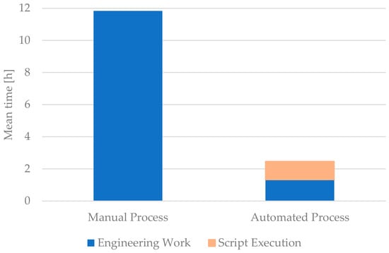
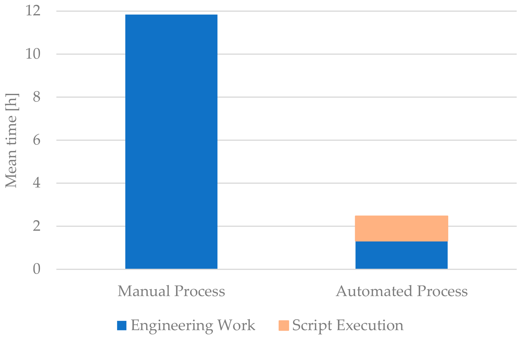
For each configuration, the total engineering time was recorded for both the original manual workflow and the automated workflow. Figure 3 and Table 1 summarizes recorded values. For the manual process, engineering times were recorded using the company’s internal activity-reporting software. The recorded times were subsequently compared with the company’s established engineering time standards (normatives), which are based on more than ten years of practical experience with the analysed product. This comparison was used to assess the consistency and plausibility of the measured manual-process times against established company reference values.
Figure 3.
Comparison of mean process times for manual and automated workflows for n = 20 customized assembly configurations.
Table 1.
Statistical summary of measured engineering time for manual and automated workflows based on n = 20 customized assembly configurations.
The reference dataset underlying the company normatives has a standard deviation of 2.8 h, whereas the standard deviation calculated for the evaluated sample of 20 configurations was 2.31 h. This difference may be attributed to the composition of the reference dataset used to establish the normative values. The reference data include engineering times recorded for both experienced designers and less experienced or newly trained designers. In contrast, all 20 configurations evaluated in the present study were prepared by experienced designers. The resulting lower variability in engineering times is therefore consistent with the more homogeneous experience level of the designers involved in the experimental evaluation.
The execution times of the automated process were measured automatically by the system. Time measurement was directly integrated into the automation script, which recorded the relevant execution times during the automated workflow. This approach eliminated manual intervention in time recording and ensured a consistent measurement procedure across all evaluated configurations.
The measured values are summarised below:
The automated process time includes both machine execution and required human intervention. The mean effective human time in the automated workflow was:
7.2. Time Reduction and Productivity Gain
Using the productivity coefficient defined in Section 6:
For mean values:
The automation therefore achieves approximately a 4.8-fold increase in overall process efficiency.
Relative time reduction is:
Thus, the total time required to prepare a customised configuration is reduced by approximately 79%.
When considering only direct human engineering effort:
This corresponds to an approximately 90% reduction in effective engineering workload.
7.3. Scalability Analysis
To evaluate industrial impact, the results were projected to an annual production volume of N = 110 customised configurations.
Manual process:
Automated Process (total execution time):
Effective Human Engineering Time
Annual engineering time savings are therefore:
Assuming 1600 productive engineering hours per year, this corresponds to approximately:
or roughly 72% of a full-time engineering position.
These results demonstrate that the automation framework substantially decouples engineering workload from configuration volume.
7.4. Economic Impact Estimation
To assess the potential economic implications of the proposed automation framework, a simplified cost model was applied. Assuming an average engineering labour cost of:
and an annual production volume of N = 110 configurations, the projected yearly engineering time savings amount to:
The corresponding annual cost reduction can be estimated as:
Given a one-time development cost of:
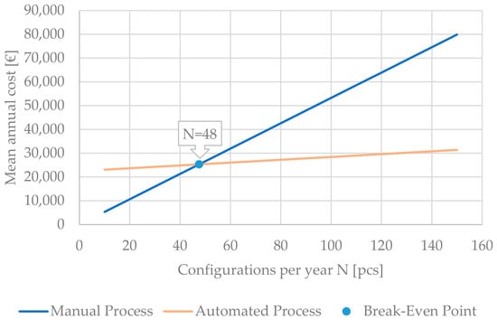
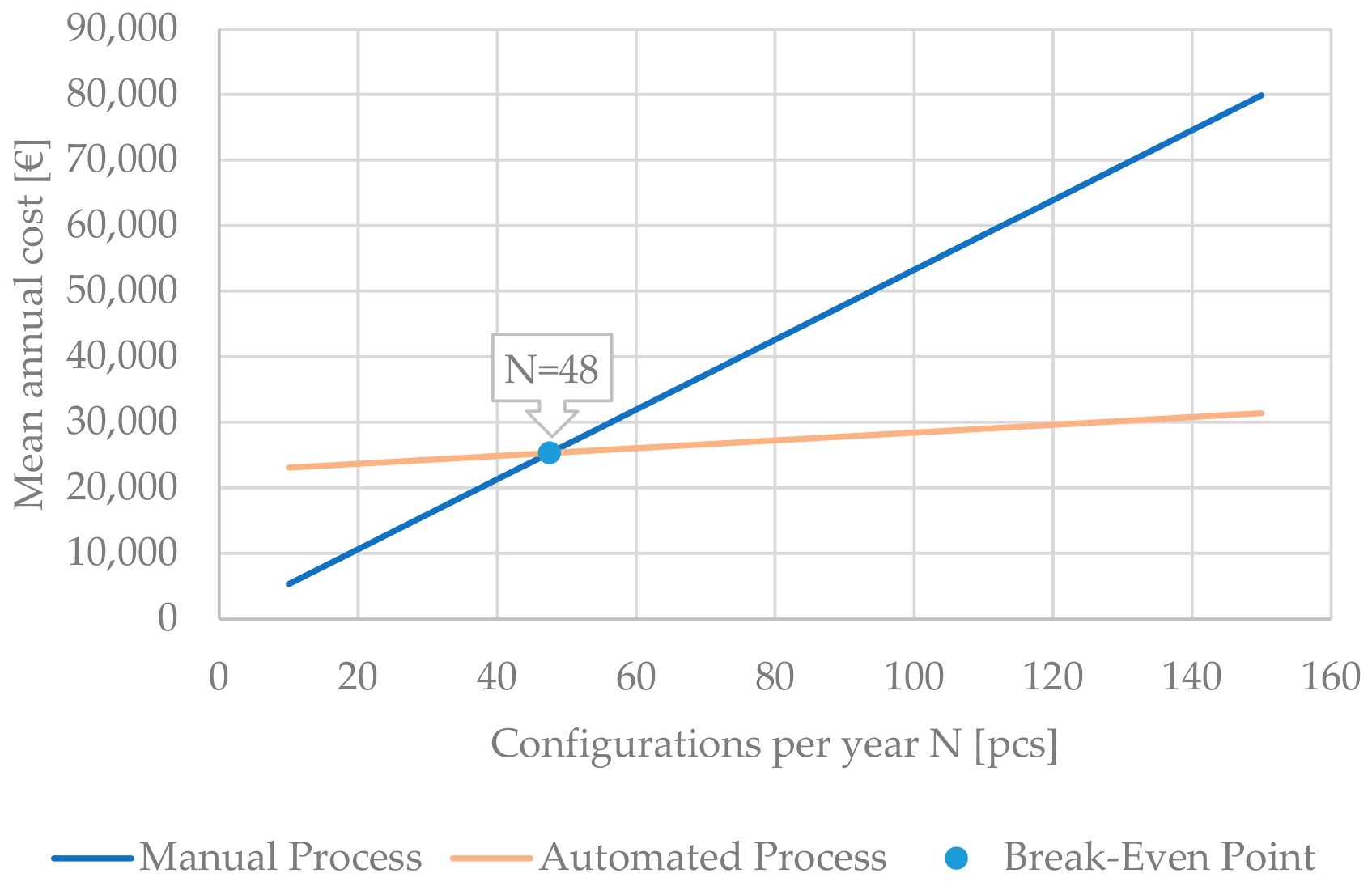
As the calculations and Figure 4 indicate, under the stated assumptions, the development cost could be recovered within the first year of operation, with estimated return on investment reaching 31%.
Figure 4.
Break-even analysis of manual and automated configuration processes as a deterministic projection over an annual volume of 10–150 configurations.
However, it should be emphasised that this estimation represents a simplified projection based on average labour cost and assumed annual production volume. Actual economic performance may vary depending on factors such as:
- Variability in configuration complexity;
- Changes in production volume;
- System maintenance costs;
- Required updates to parametric models;
- Organisational adaptation and training requirements.
Therefore, while the results indicate a strong potential for favourable economic impact, the exact return is context-dependent and should be evaluated individually for each industrial deployment.
7.5. Summary of Findings
The evaluation based on 20 experimentally analysed configurations indicates that:
- The average configuration preparation time decreased by approximately 79%;
- Direct engineering workload was reduced by nearly 90%;
- When extrapolated to an annual volume of 110 configurations, the projected reduction exceeds 1100 engineering hours;
- Under the assumed cost conditions, the automation framework demonstrates the potential for economically advantageous deployment.
Overall, the results suggest that systematic CAD automation can substantially reduce engineering effort while maintaining configurability. The economic attractiveness of the approach appears promising, although its magnitude depends on specific organisational and operational conditions.
8. Discussion
The presented results illustrate the considerable potential of combining parametric modelling with API-based automation in industrial design environments. By transforming previously manual activities into structured automated processes, engineering departments can focus more on design decisions rather than repetitive operations. In addition to reducing the time required for routine engineering tasks, the implemented automation had a positive impact on the overall quality and consistency of the resulting technical documentation.
A significant source of errors in the original manual workflow was associated with user-dependent data entry and document preparation. These errors included formal inconsistencies, such as the use of commas instead of decimal points, inconsistent use of upper- and lower-case characters, incorrect designations, typographical errors, and other unintended user mistakes. According to the internal key performance indicator (KPI) data, the long-term error rate of the existing manual process corresponded to approximately 3% when normalised to an annual volume of N = 110 configurations. These errors typically required subsequent rework before the affected documentation could be considered complete and suitable for release. By incorporating predefined design requirements and formatting rules directly into the automated workflow, a substantial part of these error sources could be eliminated. The automation therefore not only accelerated the generation of customised assemblies and their associated documentation but also ensured a more consistent application of the defined design requirements.
The effect of the proposed automation on error occurrence was also reflected in the internal KPI evaluation. Following the implementation of the automated workflow, the observed error rate decreased to approximately 0.5% for the same reference production volume. Furthermore, approximately 65% of the remaining errors were detected during the engineering review stage, before the documentation was released. These errors were therefore identified and corrected within the existing review process and did not result in rework after the release of the documentation. This finding indicates that the combination of automated processing and engineering review substantially reduces the number of errors reaching the released documentation and, consequently, the need for subsequent rework.
An important aspect of the implemented approach is the validation of input data prior to execution of the automated operations. This validation mechanism verifies whether the input parameters conform to the predefined requirements and expected data formats. As a result, invalid or inconsistent input data can be identified before they are propagated into the CAD model and subsequent documentation. This is particularly important in an integrated CAD–PLM environment, where an error introduced at an early stage could subsequently affect multiple dependent outputs. The validation therefore represents an important safeguard against the introduction of new errors by the automation itself. Within the evaluated workflow, no new errors attributable to the automated processing were identified.
Consequently, the benefits of the proposed automation extend beyond the reduction in processing time and engineering effort. By systematically incorporating design requirements, validation rules, and formatting conventions into the workflow, the approach also reduces the dependency on individual user attention during repetitive activities. This contributes to improved consistency, reduced occurrence of rework, and higher overall quality of the generated technical documentation. In this respect, automation can be considered not only as a means of improving process efficiency but also as a mechanism for enforcing predefined engineering and documentation standards.
In cases involving highly complex models or incompatible databases, the effort required to restructure and parameterise the system may exceed the expected benefits and cost savings of the proposed automation. The costs of these modifications should therefore be carefully assessed before implementation.
Although the models used in this study were parametrised to support automation, as described earlier, this parametrisation was a prerequisite for implementing the proposed process rather than the primary objective of the study. The main focus was the development and evaluation of the automated CAD–PLM workflow, while model preparation and restructuring served as enabling activities. The associated effort should therefore be considered when assessing the overall applicability and economic benefits of similar automation solutions, even though its detailed optimisation was beyond the scope of this study.
Another important consideration concerns system integration. Because the automation relies on interaction between CAD software and a PLM database, stable communication between these systems must be ensured. Differences between CAD platforms may also influence the implementation details of the automation logic. In addition, the interfaces between the CAD environment, automation layer, and PLM system must be sufficiently robust to ensure that validated data are transferred consistently throughout the entire workflow.
Despite these challenges, the benefits observed in the case study demonstrate that the methodology can provide substantial value in industrial practice. Companies dealing with configurable products and repetitive engineering workflows are particularly suitable candidates for the adoption of similar solutions. The results indicate that such an approach can simultaneously improve process efficiency, reduce the occurrence of user-induced errors and subsequent rework, and increase the consistency and quality of technical documentation. The combination of automated design generation, input-data validation, and PLM integration therefore provides a foundation for more reliable and standardised engineering workflows.
9. Generalised Framework for CAD Automation
Although the automation system developed and evaluated in this study was implemented for a specific industrial case, the primary objective was to formulate a generalized automation framework that can be applied to a broader range of engineering and industrial contexts. The specific industrial implementation presented in this study therefore serves as a case study for the practical verification of the proposed framework. In this case study, the generalized framework was instantiated and adapted to the requirements of a specific configurable product and its associated engineering workflow, thereby demonstrating how the general principles can be transformed into a functional application in industrial practice.
The first stage of the framework involves analysing the engineering workflow to identify repetitive and rule-based activities that are suitable for automation. Once these activities have been identified, the product structure is reorganised into parametrically defined modules capable of responding to variable input requirements. This step establishes a structured product representation that can be systematically processed by the automation system.
The next stage consists of defining configuration rules that formally describe the relationships between parameters, components, and design constraints. These rules provide the logical foundation for the automation process and allow product configurations to be generated consistently according to the specified requirements. After the configuration logic has been established, the automation functionality can be implemented using the programming interfaces provided by the CAD system.
An important component of the generalized framework is integration with enterprise-level data systems, such as Product Lifecycle Management (PLM) platforms. Such integration connects the automated design process with the broader product lifecycle and enables automated access to and management of relevant product data. The framework therefore extends beyond isolated CAD scripting and considers the interaction between design automation and the surrounding engineering information environment.
Finally, the generalized framework requires practical validation through an industrial case study. The generalized principles are instantiated for a specific product, implemented as a functional automation solution, and evaluated using representative engineering configurations. This validation provides evidence that the proposed framework can be translated from a general methodological concept into a practical industrial application.
The proposed approach thus provides a systematic pathway for transforming isolated automation scripts into generalized engineering automation solutions. While the specific implementation and configuration logic are necessarily dependent on the selected product and industrial environment, the underlying methodology—workflow analysis, modular parametrisation, configuration-rule definition, CAD API implementation, enterprise–system integration, and practical validation—can be transferred to other configurable products and engineering contexts. In this way, the presented case study represents a concrete instantiation of the generalized framework rather than the framework itself.
10. Conclusions
This study presented a practical methodology for automating the generation of customised CAD assemblies and technical documentation through the integration of parametric modelling, VBA scripting, CAD Application Programming Interfaces, and PLM-based data management. The proposed approach was developed and validated in a real industrial environment characterised by a high degree of product variability and repetitive engineering activities.
The results demonstrate that effective design automation requires more than the implementation of software scripts alone. Successful deployment depends on the systematic standardisation of product structures, parameter definitions, configuration logic, and data management processes. By combining these elements within a unified workflow, the developed system was able to automatically generate assembly structures, select appropriate configurations, create technical documentation, and synchronise data with the PLM environment while maintaining consistency with existing engineering practices.
Quantitative evaluation performed on twenty representative industrial configurations confirmed substantial performance improvements. The average configuration preparation time was reduced from 11.84 h to 2.47 h, corresponding to a time reduction of approximately 79%. When considering only direct human engineering effort, the reduction approached 90%, demonstrating that the majority of previously manual activities can be successfully automated. Scalability analysis further showed that the proposed approach significantly reduces the dependence of engineering workload on the number of product configurations, thereby enabling higher throughput without proportional increases in engineering resources.
From an industrial perspective, the presented methodology offers not only productivity improvements but also enhanced process consistency, reduced risk of human error, and improved reuse of engineering knowledge. The economic evaluation suggests that under typical production conditions the investment required for automation development can be recovered within a relatively short period, making the approach attractive for companies dealing with configurable products and recurring design tasks.
Several limitations should nevertheless be acknowledged. The proposed solution was validated within a specific industrial environment and relies on the availability of well-structured parametric models, standardised configuration rules, and stable CAD–PLM integration. The achieved benefits may therefore vary depending on the maturity of existing engineering data and organisational processes. Furthermore, the study focused primarily on time-based performance metrics and did not quantitatively evaluate the impact of automation on design quality, error reduction, or long-term maintainability.
Future research should investigate the integration of artificial intelligence techniques, knowledge-based reasoning systems, and generative design methods to further increase automation capabilities. Additional work could also explore the application of the proposed framework to other CAD platforms, more complex product families, and fully digitalised engineering environments incorporating digital twins and digital thread concepts. Such developments may further strengthen the role of intelligent automation in supporting efficient and scalable engineering design processes.
Author Contributions
Conceptualization, J.R.; methodology, J.R.; software, J.R.; validation, A.B.; formal analysis, A.B.; investigation, J.R.; resources, J.R.; data curation, J.R.; writing—original draft preparation, J.R.; writing—review and editing, A.B.; visualization, A.B.; project administration, J.R.; funding acquisition, A.B. All authors have read and agreed to the published version of the manuscript.
Funding
The publication was supported by institutional support for the Long-Term Conceptual Development of a Research Organisation (IP DKRVO), provided by the Ministry of Education, Youth and Sports (MŠMT) of the Czech Republic.
Data Availability Statement
The original contributions presented in this study are included in the article. Further inquiries can be directed to the corresponding author.
Conflicts of Interest
The authors declare no conflict of interest.
References
- Stark, J. Product Lifecycle Management; Decision Engineering; Springer: London, UK, 2011. [Google Scholar] [CrossRef] [Scilit]
- Stark, J. PLM and Digital Threads. In Product Lifecycle Management (Volume 1); Decision Engineering; Springer: Cham, Switzerland, 2022; pp. 403–419. [Google Scholar] [CrossRef] [Scilit]
- Camba, J.D.; Contero, M.; Pérez, D. On the integration of model-based feature information in Product Lifecycle Management systems. Int. J. Inf. Manag. 2017, 37, 611–621. [Google Scholar] [CrossRef] [Scilit]
- Shah, J.J.; Mäntylä, M. Parametric and Feature-Based CAD/CAM: Concepts, Techniques, and Applications; John Wiley & Sons: Hoboken, NJ, USA, 1995. [Google Scholar]
- Anderl, R.; Mendgen, R. Modelling with constraints: Theoretical foundation and application. Comput.-Aided Des. 1996, 28, 155–168. [Google Scholar] [CrossRef] [Scilit]
- Bidarra, R.; Bronsvoort, W. Semantic feature modelling. Comput.-Aided Des. 2000, 32, 201–225. [Google Scholar] [CrossRef] [Scilit]
- Bouma, W.; Fudos, I.; Hoffmann, C.; Cai, J.; Paige, R. Geometric constraint solver. Comput.-Aided Des. 1995, 27, 487–501. [Google Scholar] [CrossRef] [Scilit]
- Moreno, R.; Bazán, A.M. Design automation using script languages. High-Level CAD templates in Non-Parametric programs. IOP Conf. Ser. Mater. Sci. Eng. 2017, 245, 062039. [Google Scholar] [CrossRef] [Scilit]
- Dvořák, K. Management of parametric CAD model by external tools. Appl. Mech. Mater. 2013, 390, 616–620. [Google Scholar] [CrossRef] [Scilit]
- Wang, R. Development of Parametric Drawing Program Based on AutoCAD VBA. In Proceedings of the 2010 International Conference on Computational Aspects of Social Networks; IEEE: New York, NY, USA, 2010; pp. 757–760. [Google Scholar] [CrossRef] [Scilit]
- Álvares, A.J.; Ferreira, J.C.E.; Lorenzo, R.M. An integrated web-based CAD/CAPP/CAM system for the remote design and manufacture of feature-based cylindrical parts. J. Intell. Manuf. 2008, 19, 643–659. [Google Scholar] [CrossRef] [Scilit]
- Heikkinen, T.; Johansson, J.; Elgh, F. Multidisciplinary design automation—A conceptual framework for working with product model extensions. Int. J. Agil. Syst. Manag. 2020, 13, 28. [Google Scholar] [CrossRef] [Scilit]
- Amadori, K.; Tarkian, M.; Ölvander, J.; Krus, P. Flexible and robust CAD models for design automation. Adv. Eng. Inform. 2012, 26, 180–195. [Google Scholar] [CrossRef] [Scilit]
- Baxter, D.; Gao, J.; Case, K.; Harding, J.; Young, B.; Cochrane, S.; Dani, S. An engineering design knowledge reuse methodology using process modelling. Res. Eng. Des. 2007, 18, 37–48. [Google Scholar] [CrossRef] [Scilit]
- La Rocca, G.; Van Tooren, M. Enabling distributed multi-disciplinary design of complex products: A knowledge based engineering approach. J. Des. Res. 2007, 5, 333. [Google Scholar] [CrossRef] [Scilit]
- Verhagen, W.J.C.; Curran, R. Knowledge-Based Engineering Review: Conceptual foundations and research issues. In New World Situation: New Directions in Concurrent Engineering; Advanced Concurrent Engineering; Springer: London, UK, 2010; pp. 267–276. [Google Scholar] [CrossRef] [Scilit]
- Van Der Elst, S.W.G.; Van Tooren, M.J.L. Application of a knowledge engineering process to support engineering design application development. In Collaborative Product and Service Life Cycle Management for a Sustainable World; Advanced Concurrent Engineering; Springer: London, UK, 2008; pp. 417–431. [Google Scholar] [CrossRef] [Scilit]
- Chandrasegaran, S.K.; Ramani, K.; Sriram, R.D.; Horváth, I.; Bernard, A.; Harik, R.F.; Gao, W. The evolution, challenges, and future of knowledge representation in product design systems. Comput.-Aided Des. 2012, 45, 204–228. [Google Scholar] [CrossRef] [Scilit]
- Wiberg, A. Towards Design Automation for Additive Manufacturing: A Multidisciplinary Optimization Approach. Master’s Thesis, Linköping University, Linköping, Sweden, 2019. [Google Scholar] [CrossRef] [Scilit]
- Dworschak, F.; Dietze, S.; Wittmann, M.; Schleich, B.; Wartzack, S. Reinforcement learning for engineering Design automation. Adv. Eng. Inform. 2022, 52, 101612. [Google Scholar] [CrossRef] [Scilit]
- Vukašinović, N.; Duhovnik, J. Advanced CAD Modeling; Springer Tracts in Mechanical Engineering; Springer International Publishing: Cham, Switzerland, 2019. [Google Scholar] [CrossRef] [Scilit]
- Storti, D. Principles of CAD/CAM/CAE Systems; Kunwoo Lee; Addison-Wesley, Reading, MA, 1999, 582 pages, ISBN 0-201-38036-6 (US$ 91.00). Comput.-Aided Des. 2000, 32, 227–228. [Google Scholar] [CrossRef] [Scilit]
- Gao, S.; Zhao, W.; Lin, H.; Yang, F.; Chen, X. Feature suppression based CAD mesh model simplification. Comput.-Aided Des. 2010, 42, 1178–1188. [Google Scholar] [CrossRef] [Scilit]
- Camba, J.D.; Contero, M.; Company, P. Parametric CAD modeling: An analysis of strategies for design reusability. Comput.-Aided Des. 2016, 74, 18–31. [Google Scholar] [CrossRef] [Scilit]
- Li, M.; Lin, C.; Chen, W.; Liu, Y.; Gao, S.; Zou, Q. XVoxel-Based Parametric Design Optimization of Feature Models. Comput.-Aided Des. 2023, 160, 103528. [Google Scholar] [CrossRef] [Scilit]
- Zou, Q.; Feng, H.; Gao, S. Variational Direct Modeling: A framework towards integration of parametric modeling and direct modeling in CAD. Comput.-Aided Des. 2022, 157, 103465. [Google Scholar] [CrossRef] [Scilit]
- Safdar, M.; Jauhar, T.A.; Kim, Y.; Lee, H.; Noh, C.; Kim, H.; Lee, I.; Kim, I.; Kwon, S.; Han, S. Feature-based translation of CAD models with macro-parametric approach: Issues of feature mapping, persistent naming, and constraint translation. J. Comput. Des. Eng. 2020, 7, 603–614. [Google Scholar] [CrossRef] [Scilit]
- Hanayneh, L.; Wang, Y.; Wang, Y.; Wileden, J.C.; Qureshi, K.A. Feature Mapping Automation for CAD Data Exchange. In Proceedings of the ASME 2008 International Design Engineering Technical Conferences and Computers and Information in Engineering Conference, Brooklyn, NY, USA, 3–6 August 2008; pp. 1257–1266. [Google Scholar] [CrossRef] [Scilit]
- Gujarathi, G.; Ma, Y. Parametric CAD/CAE integration using a common data model. J. Manuf. Syst. 2011, 30, 118–132. [Google Scholar] [CrossRef] [Scilit]
- Benaouali, A.; Kachel, S. An automated CAD/CAE integration system for the parametric design of aircraft wing structures. J. Theor. Appl. Mech./Mech. Teoretyczna I Stosow. 2017, 55, 447–459. [Google Scholar] [CrossRef] [Scilit]
- Chapman, C.B.; Pinfold, M. The application of a knowledge based engineering approach to the rapid design and analysis of an automotive structure. Adv. Eng. Softw. 2001, 32, 903–912. [Google Scholar] [CrossRef] [Scilit]
- Kwong, C.; Jiang, H.; Luo, X. AI-based methodology of integrating affective design, engineering, and marketing for defining design specifications of new products. Eng. Appl. Artif. Intell. 2015, 47, 49–60. [Google Scholar] [CrossRef] [Scilit]
- Ortner-Pichler, A.; Landschützer, C. Integration of parametric modelling in web-based knowledge-based engineering applications. Adv. Eng. Inform. 2022, 51, 101492. [Google Scholar] [CrossRef] [Scilit]
- Desouza, K.C. Managing Software Engineering knowledge. Knowl. Manag. Res. Pract. 2004, 2, 63–64. [Google Scholar] [CrossRef] [Scilit]
- Dworschak, F.; Kügler, P.; Schleich, B.; Wartzack, S. Model and knowledge representation for the reuse of design process knowledge supporting design automation in mass customization. Appl. Sci. 2021, 11, 9825. [Google Scholar] [CrossRef] [Scilit]
- Yoo, S.; Lee, S.; Kim, S.; Hwang, K.H.; Park, J.H.; Kang, N. Integrating deep learning into CAD/CAE system: Generative design and evaluation of 3D conceptual wheel. Struct. Multidiscip. Optim. 2021, 64, 2725–2747. [Google Scholar] [CrossRef] [Scilit]
- Santos, L.; Schleicher, S.; Caldas, L. Automation of CAD models to BEM models for performance based goal-oriented design methods. Build. Environ. 2016, 112, 144–158. [Google Scholar] [CrossRef] [Scilit]
- Rasheed, A.; San, O.; Kvamsdal, T. Digital Twin: Values, challenges and enablers from a modeling perspective. IEEE Access 2020, 8, 21980–22012. [Google Scholar] [CrossRef] [Scilit]
- Saaksvuori, A.; Immonen, A. Product Lifecycle Management; Springer: Berlin/Heidelberg, Germany, 2004. [Google Scholar] [CrossRef] [Scilit]
- Abramovici, M. Future Trends in Product Lifecycle Management (PLM). In The Future of Product Development; Springer: Berlin/Heidelberg, Germany, 2007; pp. 665–674. [Google Scholar] [CrossRef] [Scilit]
- Duda, J.; Oleszek, S.; Santarek, K. Product Lifecycle Management (PLM) in the context of industry 4.0. In Advances in Manufacturing III; Lecture Notes in Mechanical Engineering; Springer: Cham, Switzerland, 2022; pp. 171–185. [Google Scholar] [CrossRef] [Scilit]
- Li, J.; Tao, F.; Cheng, Y.; Zhao, L. Big Data in product lifecycle management. Int. J. Adv. Manuf. Technol. 2015, 81, 667–684. [Google Scholar] [CrossRef] [Scilit]
- Sudarsan, R.; Fenves, S.; Sriram, R.; Wang, F. A product information modeling framework for product lifecycle management. Comput.-Aided Des. 2005, 37, 1399–1411. [Google Scholar] [CrossRef] [Scilit]
- Mostefai, S.; Bouras, A.; Batouche, M. Data Integration in a PLM Perspective for Mechanical Products. Int. Arab. J. Inf. Technol. 2005, 2, 141–147. [Google Scholar] [CrossRef] [Scilit]
- Peng, T.; Trappey, A.J. A step toward STEP-compatible engineering data management: The data models of product structure and engineering changes. Robot. Comput.-Integr. Manuf. 1998, 14, 89–109. [Google Scholar] [CrossRef] [Scilit]
- Romero, D.; Wuest, T.; Harik, R.; Thoben, K. Towards a Cyber-Physical PLM environment. IFAC-Pap. 2020, 53, 10911–10916. [Google Scholar] [CrossRef] [Scilit]
- Gopalakrishnan, S.; Hartman, N.W.; Sangid, M.D. Integrating Materials Model-Based Definitions into Design, Manufacturing, and Sustainment: A Digital Twin Demonstration of Incorporating Residual Stresses in the Lifecycle Analysis of a Turbine Disk. J. Comput. Inf. Sci. Eng. 2020, 21. [Google Scholar] [CrossRef] [Scilit]
- Forrai, M.; Gavačová, J.; Gulan, L. A practical methodology for creating robust parametric surface-based models in automotive engineering. Procedia CIRP 2016, 50, 484–489. [Google Scholar] [CrossRef] [Scilit][Green Version]

Disclaimer/Publisher’s Note: The statements, opinions and data contained in all publications are solely those of the individual author(s) and contributor(s) and not of MDPI and/or the editor(s). MDPI and/or the editor(s) disclaim responsibility for any injury to people or property resulting from any ideas, methods, instructions or products referred to in the content. |
© 2026 by the authors. Licensee MDPI, Basel, Switzerland. This article is an open access article distributed under the terms and conditions of the Creative Commons Attribution (CC BY) license.