


Abstract
The control of Dual-Star Induction Machines (DSIMs) with high performance remains a challenging task, particularly in the presence of parameter variations and under sensorless operation. In practice, widely used controllers such as Proportional–Integral (PI) and classical sliding mode (SM) often reach their limits, especially in terms of dynamic responses, sensitivity to disturbances, and chattering, which can negatively affect system stability and efficiency. In this work, an improved Rotor Flux-Oriented Control (RFOC) strategy is proposed. It combines a super-twisting sliding mode (STSM) speed controller with a Model Reference Adaptive System (MRAS) observer. The STSM controller ensures faster convergence and enhanced robustness while significantly reducing chattering. Meanwhile, the MRAS observer enables accurate rotor speed estimation without mechanical sensors, thereby simplifying the system and improving reliability. The control scheme is developed using the Xilinx System Generator (XSG) in a fixed-point environment, providing an FPGA-oriented and compatible simulation framework. To assess its effectiveness, the proposed method is evaluated through several simulation scenarios and compared with conventional RFOC-PI and RFOC-SM approaches. The results demonstrate clear improvements in dynamic performance, disturbance rejection capability, and steady-state accuracy. Overall, the proposed approach provides a practical and efficient solution for DSIM drive systems operating under demanding conditions.
1. Introduction
Dual-Star Induction Machines (DSIMs) are increasingly used in automotive, railway, marine, aerospace, and renewable-energy applications due to their high fault tolerance, efficient power sharing between the two stator windings, reduced torque ripple, and relatively simple control implementation [1,2]. Despite these advantages, the mathematical modeling of DSIMs is inherently more complex than conventional induction motors, and the strong coupling between flux and torque complicates the design of effective controllers. Advanced vector-control strategies, such as Rotor Flux-Oriented Control (RFOC), are commonly adopted to achieve torque–flux decoupling similar to that of DC machines [3].
RFOC structures traditionally rely on Proportional–Integral (PI) speed controllers. Although straightforward to implement, PI regulators are sensitive to parameter variations, modeling uncertainties, and external disturbances, which limits their robustness [4]. To achieve a better dynamic performance, researchers have explored various nonlinear control techniques, such as sliding mode control (SMC), fuzzy logic, backstepping, and adaptive methods [5]. SMC is particularly attractive due to its robustness and strong disturbance-rejection capability; however, classical SMC suffers from chattering, as widely reported [6,7].
Fuzzy logic has been combined with sliding mode control (SMC) to adaptively tune the switching gain, thereby enhancing the robustness and dynamic performance [8,9]. In [8], a fuzzy SMC strategy was proposed for doubly salient induction motors (DSIMs), demonstrating superior robustness and dynamic response compared with conventional PI controllers. Similarly, ref. [9] developed a fuzzy fast-terminal SMC for switched reluctance motors, achieving high tracking accuracy and reduced chattering. Nonetheless, the integration of fuzzy logic with SMC increases controller complexity and complicates parameter tuning [10]. To address these challenges, the super-twisting algorithm, a second-order SMC technique, has emerged as an attractive solution for maintaining robustness while reducing chattering and preserving simpler implementation. This method only requires the sliding variable, facilitating practical deployment. In particular, ref. [11] demonstrated that incorporating a super-twisting controller within a direct torque control (DTC) framework leads to smoother torque profiles and improved dynamic performance.
The implementation of advanced control strategies requires accurate rotor speed information. Using mechanical sensors, such as encoders, increases both the cost and system complexity while potentially reducing reliability. As a result, sensorless control has become widely adopted, improving robustness and simplifying maintenance. However, many sensorless techniques still depend on precise motor parameters, which can degrade the performance when parameter variations occur. Various sensorless strategies have been investigated for DSIMs. Recent reviews [12,13,14,15] highlight approaches such as sliding mode observers, extended Kalman filters, neural networks, and Model Reference Adaptive Systems (MRASs). Among these, MRAS-based estimators are particularly attractive for rotor speed estimation due to their high accuracy, fast dynamic response, low computational burden, robustness to measurement noise, suitability for real-time implementation on DSP or FPGA platforms, and overall cost-effectiveness.
Beyond control design, the choice of hardware platform plays a critical role in the overall system performance, as high-speed and efficient control requires a substantial computational capability. Microcontrollers (e.g., STM32) and DSPs are commonly used in industrial drives and can provide a satisfactory performance for many applications. In contrast, FPGAs offer significant advantages, including the parallel execution of multiple complex algorithms, low-latency control, and deterministic timing, making them particularly suitable for high-performance or research-oriented applications [16,17,18]. Traditionally, FPGA development relies on hardware description languages such as VHDL or Verilog, which can be complex and time-consuming. In this work, the Xilinx System Generator (XSG) is employed as a high-level tool that automates VHDL code generation, enabling the rapid, portable, and platform-independent implementation of control systems across different FPGA architectures [19,20].
Motivated by these considerations, this paper proposes a hybrid sensorless control strategy for Dual-Star Induction Machines that combines RFOC with a super-twisting sliding mode (STSM) speed controller and an adaptive MRAS-based observer for speed estimation. The main contribution of this work is the unified integration of these established techniques within a DSIM-oriented framework, along with an FPGA-oriented fixed-point simulation-based XSG. This coordinated approach improves the dynamic performance, robustness, and chattering mitigation. The effectiveness of the proposed method is validated through comparative analysis with conventional control strategies.
The structure of this paper is as follows. Section 2 presents the DSIM model and RFOC fundamentals. Section 3 details the speed controllers. Section 4 introduces the adaptive MRAS observer. Section 5 reports the simulation results, comparing controller performance and evaluating the MRAS estimator. Section 6 describes the FPGA-compatible implementation using the XSG-based fixed-point simulation framework. Finally, Section 7 concludes the paper by highlighting the main contributions and summarizing the key findings.
2. DSIM Rotor Field-Oriented Approach
2.1. Model of DSIM
This study investigates a Dual-Star Induction Machine (DSIM) with two star-connected three-phase stator windings, electrically displaced by 30° and supplied by voltage sources of equal amplitude and frequency with the same phase shift [21]. The machine’s behavior is described by its mathematical model, which captures the electrical dynamics of each winding. The voltage equations, forming the foundation for subsequent control design, are presented below:
The flux equations are established as shown below:
The electromagnetic torque equation is given as follows:
The mechanical formula is illustrated as:
In the above equations, represent stator voltage, stator flux, and stator current, respectively. and indicate the leakage inductances of the stator windings for the first and second star circuits, whereas corresponds to the rotor leakage inductance. The stator and rotor resistances are given by and , respectively. defines the mutual inductance between the two stator windings, while describes the cyclic mutual inductance between the stator and rotor. With denoting the mechanical angular speed of the rotor, the stator electrical angular speed, the rotor electrical angular speed, and the slip angular speed. The number of pole pairs is indicated by represents the rotor inertia, is the viscous friction coefficient, the electromagnetic torque, and the load torque.
2.2. DSIM RFOC
The main principle of the Rotor Flux-Oriented Control (RFOC) is to operate the induction motor similarly to a DC machine by decoupling the torque and flux. This is accomplished by aligning the rotor flux vector with the direct axis (d-axis) of the Park reference frame, effectively forcing the quadrature-axis flux component to zero [22,23]:
By replacing Equation (7) in Equation (4) and simplifying, the rotor flux expression is obtained as follows:
Through Equation (8), the rotor current is expressed as follows:
By substituting Equations (7) and (9) into Equation (3) and simplifying, the stator flux expression is presented as follows:
where .
By replacing Equation (9) with Equation (2) and simplifying, we obtain:
where .
The electromagnetic torque, given in Equation (5), can be expressed as follows:
Substituting Equations (7) and (10) into Equation (2) yields the direct and quadrature stator voltages expressions:
The DSIM equations are rewritten to decouple the d–q axes and simplify the computation of the stator current controller coefficients:
where
3. DSIM Speed Controller
3.1. Speed Control Using a Proportional–Integral Controller
The conventional fixed-gain PI controller is typically expressed as follows:
The controller gains and are usually tuned under nominal operating conditions, often using pole-placement techniques, and remain constant during operation. In this work, the PI controller gains are determined using pole compensation to obtain the desired closed-loop speed dynamics. From Equation (6), the transfer function between the electromagnetic torque and the rotor speed is expressed as:
The PI controller is mathematically defined as follows:
where .
The parameters of the speed controller are determined based on open-loop time constant compensation. The proportional gain is selected such that the closed-loop time constant is four times smaller than that of the open loop. A pole–zero compensation approach is adopted, where a controller of zero cancels the mechanical pole. Consequently, the controller parameters can be expressed as and .
Despite its simplicity, the fixed-gain PI controller remains sensitive to parameter variations and external disturbances, which may degrade the overall performance. To address these limitations and enhance robustness, a sliding mode controller (SMC) can be introduced, offering improved adaptability to system uncertainties and disturbances.
3.2. Speed Control Using a Sliding Mode Controller
Sliding mode control (SMC) offers several advantages for speed control, particularly in addressing the limitations of conventional Proportional–Integral (PI) controllers. Its key features include fast transient response, strong robustness to system uncertainties, and low sensitivity to matched disturbances.
An SMC-based controller is typically designed in two steps. First, a sliding surface is defined to represent the desired system dynamics. Then, a control law is developed to drive the system states toward this surface and maintain them on it [7,24]. In this work, the sliding mode speed controller is used to generate the reference electromagnetic torque. Accordingly, Equation (6) can be rewritten as follows:
Let denote the desired speed and the actual speed. The tracking error is defined as . Based on this error, the sliding surface can be expressed as follows [11]:
where is a positive constant.
The corresponding expression of the control law is given in Equation (22) [7]:
Here, the equivalent control governs the system behavior on the sliding surface, while the discontinuous term acts as a switching function to compensate for disturbances and parameter variations. The discontinuous component can be , written as follows:
where is a positive constant.
Owing to its discontinuous nature, this term leads to chattering effects, which can be attenuated by using a continuous (smooth) control function. The equivalent control law is derived by imposing the sliding condition (). The derivative of the sliding surface is defined as [25]:
Considering , the previous equation can be rewritten as:
To fulfill the equivalent control concept , we can obtain:
According to Equation (23), the reference torque is expressed as:
Once the SMC law is established, it is essential to assess the system stability. This can be done using the Lyapunov stability criterion, as described below [26]:
The existence and reachability of the sliding mode are guaranteed when the time derivative of the Lyapunov function is a negative definite. Based on the Lyapunov candidate introduced in Equation (28), the derivative of is obtained as:
Therefore, the reachability condition of the sliding mode speed controller is ensured. Combining Equations (25) and (29) yields:
Hence, the stability condition is confirmed.
Nevertheless, classical SMC designs may induce chattering due to high-frequency switching, which can negatively affect actuator performance. To overcome this limitation, advanced strategies such as the super-twisting sliding mode controller (STSMC) are commonly employed, providing continuous control action while preserving the robustness of conventional sliding mode control.
3.3. Speed Control Using a Sliding Mode Super-Twisting Controller
High-order sliding mode (HOSM) control has been proposed to overcome the inherent limitations related to the relative degree and to significantly reduce the chattering phenomenon observed in conventional sliding mode control (SMC). Among the various HOSM strategies, the super-twisting sliding mode controller (STSMC) has attracted significant attention due to its superior robustness and enhanced dynamic performance, particularly in electric driving applications [27]. As a second-order sliding mode technique, the STSMC ensures finite-time convergence through a continuous control action, thereby eliminating the high-frequency switching associated with classical first-order SMC [28]. This property is achieved by exploiting the tracking error and its intrinsic dynamics without requiring explicit differentiation, which simplifies practical implementation. Furthermore, the STSMC preserves the inherent robustness of SMC against parameter uncertainties and external disturbances, while effectively attenuating chattering. It is particularly suitable for systems with a relative degree equal to one and can be extended to more complex dynamics without requiring higher-order derivatives of the sliding variable. Consequently, the super-twisting algorithm provides an effective trade-off between robustness, accuracy, and implementation simplicity, making it a powerful and reliable solution for high-performance speed control systems operating under smooth disturbances with bounded gradients.
Consider the following nonlinear system:
where is the sliding surface, is the control signal, and and are uncertain functions with upper and lower bounds.
To guarantee convergence of the sliding surface to zero in the presence of disturbances and uncertainties, the functions and must verify the following conditions:
According to Equations (20) and (21), the derivative of the surface is written as follows:
The STSMC control law is composed of two parts, and , represented as follows [29,30]:
where
where and are chosen as positive constants, and the parameter r presents the degree of nonlinearity. The sufficient conditions by Levant to offer a finite-time convergence are given as follows [31]:
where and are considered the bounds of the function . By identification, and using Equation (31) together with the condition in Equation (32), the variable and can be expressed as follows:
where
From Equation (38) and based the condition of Equation (36), we have and we can choose the and :
4. Design of an Adaptive MRAS Speed Observer
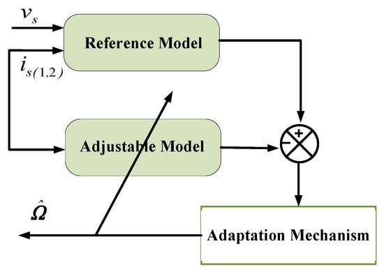
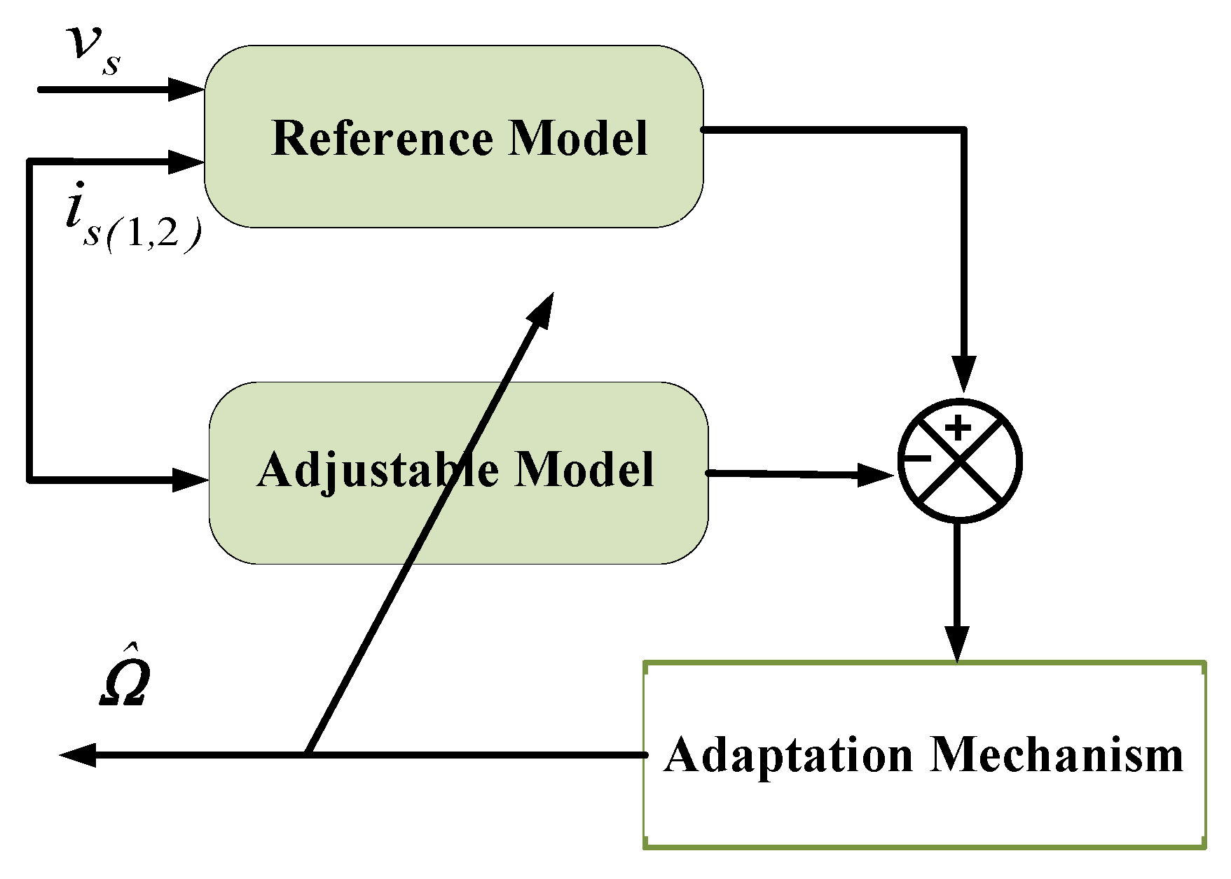
The Model Reference Adaptive System (MRAS) is a well-established approach for sensorless speed estimation in AC drives, owing to its simple structure, satisfactory accuracy, and suitability for real-time applications. In this study, an adaptive MRAS observer is designed for the DSIM to estimate the rotor speed without mechanical sensors, thereby improving system reliability and reducing hardware costs [32]. The proposed scheme relies on two models: a reference model that is independent of the rotor speed and an adaptive model that explicitly depends on it, as shown in Figure 1. The mismatch between the outputs of these two models is processed through an adaptation mechanism to generate the estimated rotor speed [33]. It is important to note that the proposed MRAS is solely dedicated to speed estimation, while the electrical variables are regulated independently by the inner current and flux control loops.
Figure 1.
Functional diagram of the adaptive MRAS observer.
The observer is formulated using simple algebraic expressions, which facilitates its implementation on FPGA-based platforms. The rotor speed is obtained by minimizing the error between the reference and adaptive models. Although parameter variations, such as temperature changes or magnetic saturation, may influence estimation accuracy, the proposed MRAS demonstrates sufficient robustness under the considered operating conditions.
4.1. MRAS Modeling
The DSIM model is transformed from the synchronous d–q frame to the stationary frame to simplify MRAS implementation. From this model, two independent expressions of the rotor flux are obtained.
The first expression corresponds to the reference model, where the rotor flux is estimated using the stator voltage equations:
where is the operator place.
The second expression corresponds to the adaptive model, where the rotor flux is based on voltage equations and depends on the rotor speed:
where and denote the components of the rotor flux estimated by the reference and adaptive models, respectively, and represents the inverse of the rotor time constant.
Using the errors and as a function of and :
This leads us to the following system of equations:
This expression can be represented in matrix form as follows:
4.2. Development and Derivation of the Adaptation Mechanism
The adaptation law plays a key role in the estimation process by ensuring system stability and the asymptotic convergence of the estimated variables toward their true values. To guarantee hyperstability in time-varying linear systems, the adaptation mechanism is designed based on Popov’s inequality. In this work, the proposed adaptation law is integrated within the rotor flux-based MRAS scheme. Accordingly, Equation (45) can be expressed as follows:
where
The necessary and sufficient condition for hyperstability is that the considered transfer matrix is strictly positive real. Under this condition, system stability is guaranteed when all eigenvalues have negative real parts. In addition, the second term of the matrix formulation must converge to zero or at least remain bounded with minimal energy. Meanwhile, the adaptation mechanism must satisfy Popov’s hyperstability criterion, which can be expressed as follows:
Following the formulation introduced in [34], the adaptation law considered in this work is expressed as follows:
By substituting the expressions of and into Popov’s inequality, we obtain:
The following relationship allows us to obtain the solution to this equation:
When Popov’s inequality is resolved with the preceding expression, the following relationships emerge:
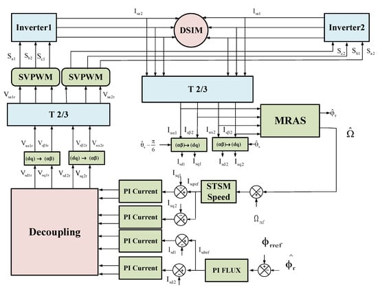
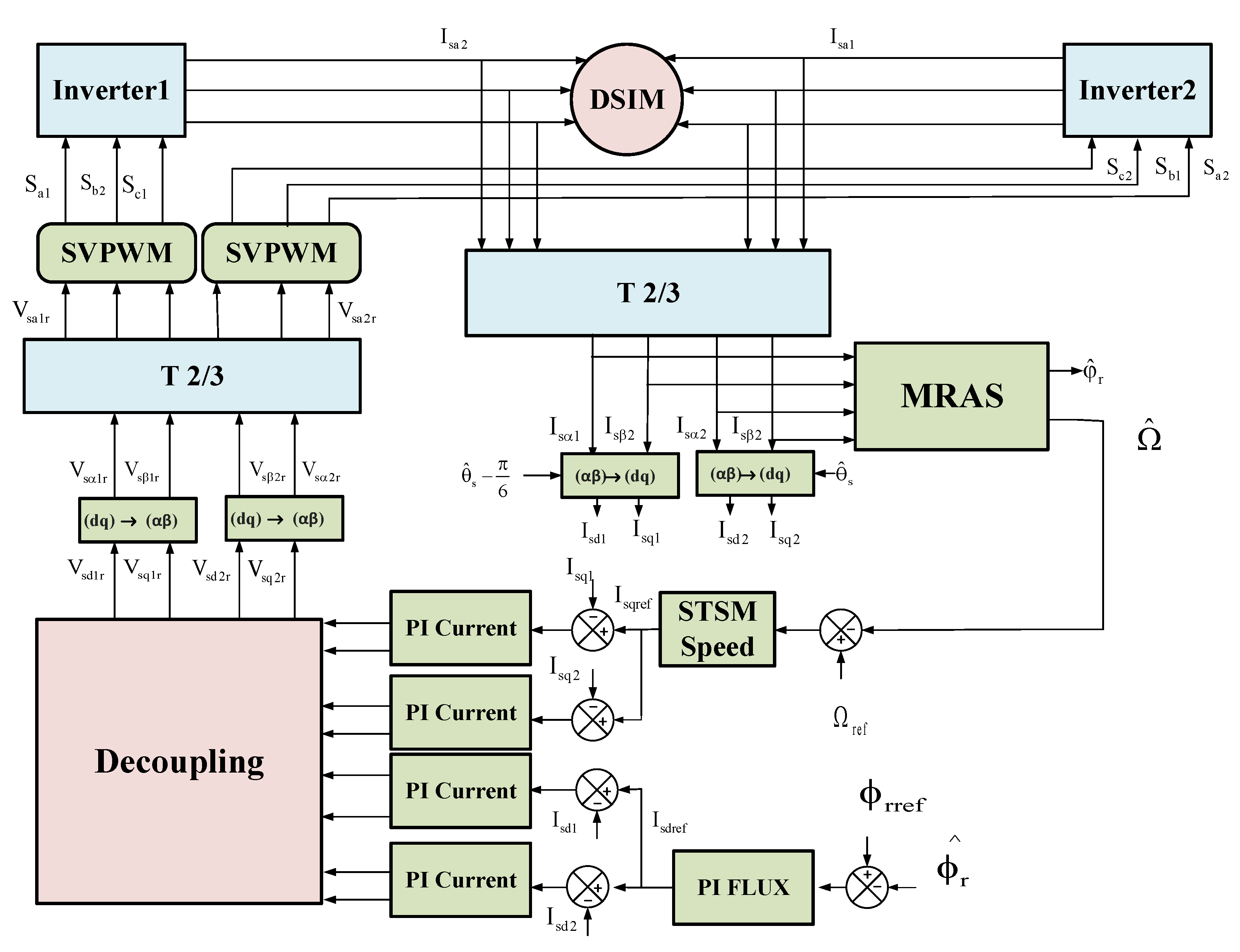
To implement the adaptation mechanism, a Proportional–Integral (PI) controller is employed, where the integral and proportional gains are respectively determined. Figure 2 illustrates the block diagram of RFOC-STSMC with an adaptive MRAS observer.
Figure 2.
Block diagram of the DSIM under RFOC-STSM with an adaptive MRAS.
5. Simulation Results
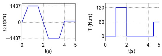
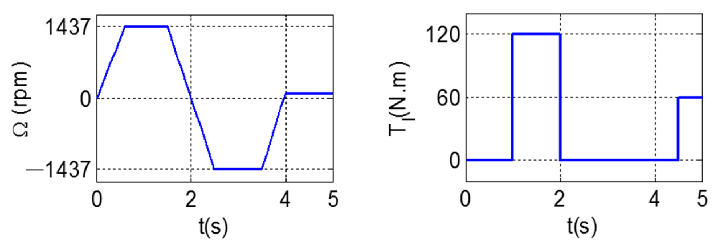
To validate the DSIM performance under the proposed RFOC-STSM control and assess the effectiveness of the adaptive MRAS, numerical simulations were conducted under different operating speeds and load torques, as illustrated in Figure 3. The nominal machine parameters are summarized in Appendix A.
Figure 3.
Reference motor speed and load torque variations.
The performance of the considered control strategies (RFOC-PI, RFOC-SM, and RFOC-STSM) is evaluated using a set of quantitative indices that reflect different dynamic and steady-state characteristics. In particular, the Integral Square Error (ISE), Integral Absolute Error (IAE), and Integral Time Absolute Error (ITAE) are adopted to assess the tracking performance and transient behavior. These indices are defined as [35]:
In addition, the ripple is used as a performance indicator to evaluate the smoothness of the electromagnetic torque and stator current. It is defined as the relative peak-to-peak variation in the signal with respect to its average steady-state value and is expressed as:
where X represents either the electromagnetic torque or the stator current. These performance metrics provide a comprehensive evaluation framework for comparing the effectiveness of the different control strategies.
5.1. Comparison of the Three Approaches
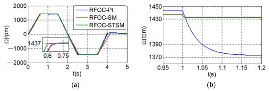
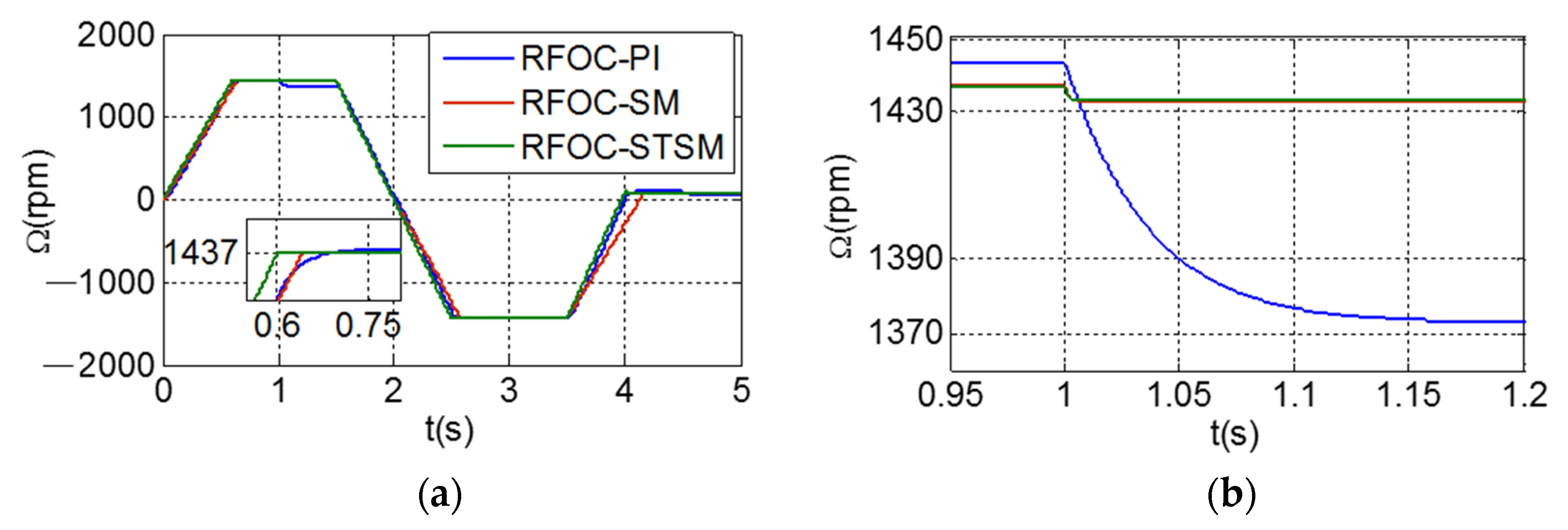
Figure 4 compares the rotor speed responses of the DSIM under load torque disturbances using three control strategies: RFOC-PI, RFOC-SM, and RFOC-STSM. All controllers ensure stable operation and acceptable dynamic performance during startup while accurately tracking the reference speed profile; however, clear differences appear in transient behavior and disturbance rejection. A load torque of 120 Nm is applied at t = 1 s to evaluate the robustness of the control strategies under sudden disturbance conditions. The RFOC-PI exhibits the largest speed deviation when the load is applied at t = 1 s, with a speed drop of about 62 rpm and a slower dynamic response characterized by a settling time of 0.75 s. In contrast, the RFOC-SM significantly improves robustness, reducing the speed drop to approximately 4 rpm and decreasing the settling time to 0.65 s. The proposed RFOC-STSM achieves the best performance, maintaining nearly the same minimal speed drop (≈4 rpm) while ensuring the fastest dynamic response with a settling time of 0.61 s. This improvement confirms the superior robustness and disturbance rejection capability of the STSM-based control, ensuring precise speed regulation and enhanced stability.
Figure 4.
DSIM speed response under three control strategies: (a) speed curves; (b) zoomed view.
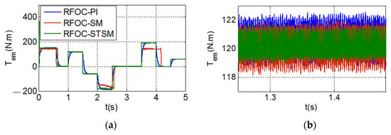
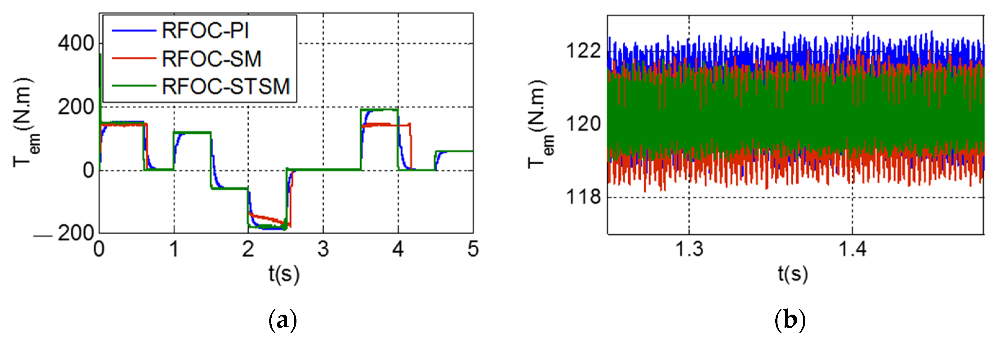
Figure 5 presents the electromagnetic torque responses of the DSIM under RFOC-PI, RFOC-SM, and RFOC-STSM control strategies in the presence of load torque disturbances. The comparison highlights clear differences in the dynamic performance and torque quality among the three approaches. The RFOC-STSM strategy provides the smoothest torque response with the lowest ripple level (2.44%), confirming its effectiveness in reducing oscillations and improving steady-state behavior. In contrast, the RFOC-SM exhibits higher torque ripples (3.49%) due to the chattering phenomenon inherent to the first-order sliding mode control, while the RFOC-PI also shows relatively higher ripples (3.48%) and slower dynamic responses. These results validate the superiority of the super-twisting sliding mode approach in mitigating chattering and enhancing both the dynamic performance and torque smoothness.
Figure 5.
DSIM electromagnetic torque response under three control strategies: (a) torque curves; (b) zoomed view.
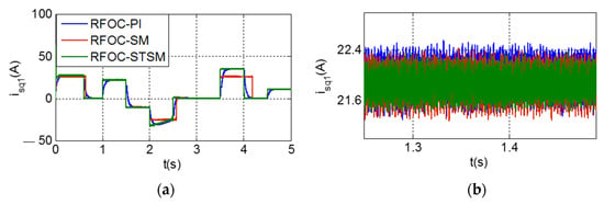
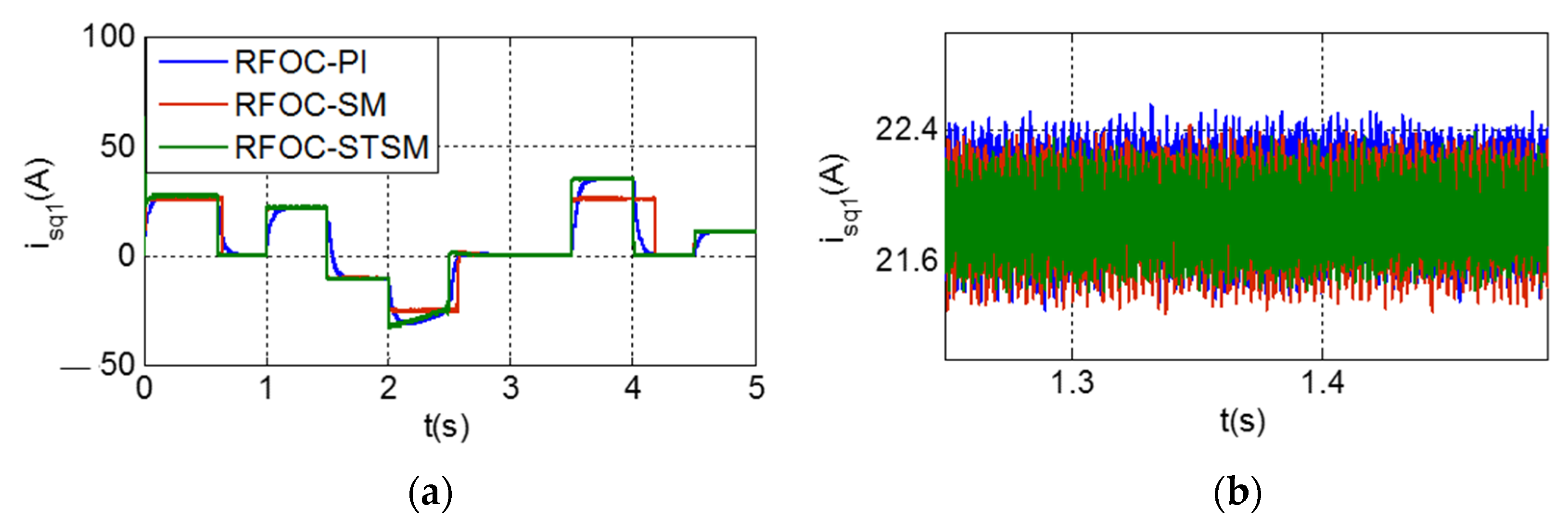
Figure 6 illustrates the stator current component under the RFOC-PI, RFOC-SM, and RFOC-STSM control strategies. The obtained results indicate that all controllers are able to ensure satisfactory tracking of the reference current trajectory, confirming the effectiveness of the overall control structure. But there are clear differences in the quality of the current and the amount of ripples. The RFOC-STSM controller provides the smoothest current waveform, achieving the lowest ripple level (4.88%), which reflects its strong capability in attenuating oscillations and improving current regulation. In contrast, the RFOC-SM exhibits more pronounced fluctuations (5.94%) due to the chattering effect associated with classical sliding mode control, while the RFOC-PI presents a slightly lower performance in terms of smoothness with a ripple level of (5.92%). These results are consistent with the previous torque analysis and confirm that the super-twisting sliding mode strategy significantly enhances current quality by effectively reducing chattering and enhancing current smoothness and overall control quality under the considered operating conditions.
Figure 6.
DSIM stator current response under three control strategies: (a) stator current curves; (b) zoomed view.
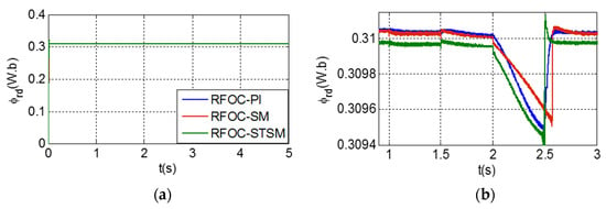
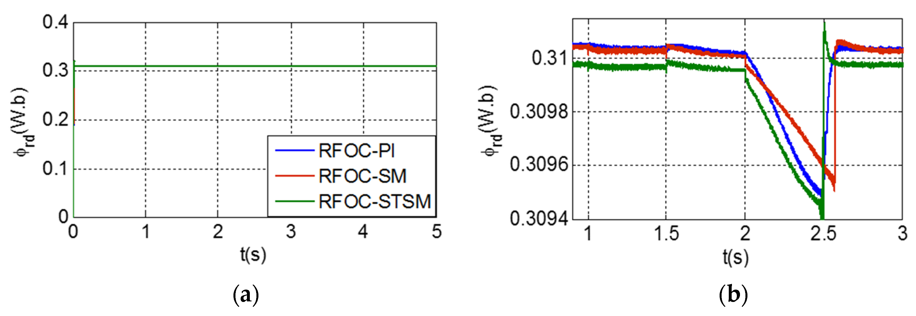
Figure 7 illustrates the rotor flux response of the dual-star induction motor under the RFOC-PI, RFOC-SM, and RFOC-STSM control strategies. Prior to the speed variation, all methods maintain the flux close to its reference value (0.31 Wb), confirming effective steady-state regulation. During the transient induced by the speed change, a slight flux deviation is observed for all controllers. However, the RFOC-STSM strategy achieves the fastest recovery toward the reference value, whereas the RFOC-PI and RFOC-SM exhibit slower convergence. This behavior highlights the superior dynamic response and robustness of the STSM-based approach in preserving flux stability under varying operating conditions.
Figure 7.
DSIM rotor flux response under three control strategies: (a) rotor flux curves; (b) zoomed view.
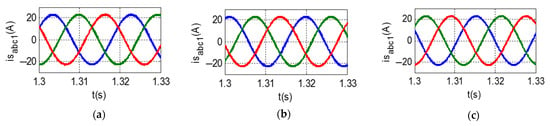
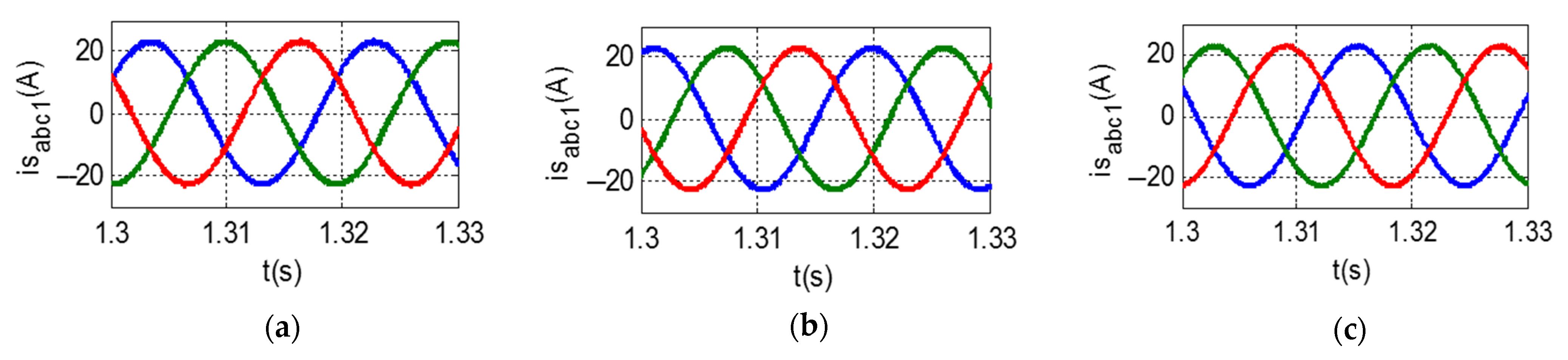
Figure 8 illustrates the stator current waveforms in the (a, b, c) frame under the different control strategies. The comparison highlights the quality of the phase currents in terms of waveform smoothness and distortion. The RFOC-STSM approach achieves a significant reduction in current distortion, resulting in more sinusoidal waveforms and improved current quality. This improvement demonstrates the effectiveness of the super-twisting algorithm in enhancing current waveform quality, thereby contributing to a better overall system performance.
Figure 8.
Zoom of the DSIM stator current response under the three control strategies and rotor flux response under three control strategies: (a) RFOC-PI; (b) RFOC-SM; and (c) RFOC-STSM.
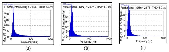
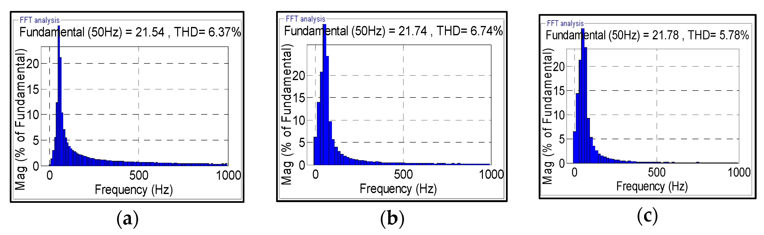
Figure 9 presents a comparison of the total harmonic distortion (THD) obtained under the RFOC-PI, RFOC-SM, and RFOC-STSM control strategies. The THD values are evaluated under identical steady-state operating conditions, using the same sampling period and a sufficiently long time window after system convergence to ensure accurate harmonic assessment. The results clearly show that the RFOC-STSM controller achieves the lowest THD value (5.78%) compared to (6.37%) for RFOC-PI and (6.74%) for RFOC-SM. This improvement confirms a reduction in harmonic content and better quality of the current waveform. The superior performance of the RFOC-STSM strategy is attributed to its ability to reduce the chattering phenomenon, which leads to smoother current waveforms and improved harmonic performance under the considered operating conditions.
Figure 9.
Total harmonic distortion (THD) for the three control strategies: (a) RFOC-PI; (b) RFOC-SM; and (c) RFOC-STSM.
The integral performance indices, namely ISE, IAE, and ITAE, provide a comprehensive assessment of the tracking accuracy and dynamic behavior of the considered control strategies. The obtained results clearly indicate that the proposed controller achieves superior performance in terms of minimizing tracking errors and improving transient response. In comparison, the conventional PI and first-order sliding mode controllers exhibit significantly higher error levels, reflecting less accurate tracking and slower dynamic convergence. Overall, these results confirm the effectiveness of the proposed approach in enhancing both steady-state and dynamic performances.
Table 1 presents a comprehensive comparison of the dynamic performance of the DSIM under the three considered control strategies. The reported metrics include torque ripple, stator current ripple, settling time, performance indices, and speed deviation under load disturbances. The results demonstrate that the RFOC-STSM controller consistently achieves the best performance among all methods, ensuring reduced speed deviations, faster transient response, and lower ripple levels in both the torque and stator current. These outcomes clearly highlight the superiority of the proposed control strategy in enhancing system robustness and dynamic behavior when compared to conventional PI and first-order sliding mode controllers.
Table 1.
Comparison of stator current ripple, torque ripple, THD, ISE, IAE, ITAE, settling time, and speed drop under three control strategies.
5.2. Effectiveness of the Adaptive MRAS Combined with the RFOC-STSM
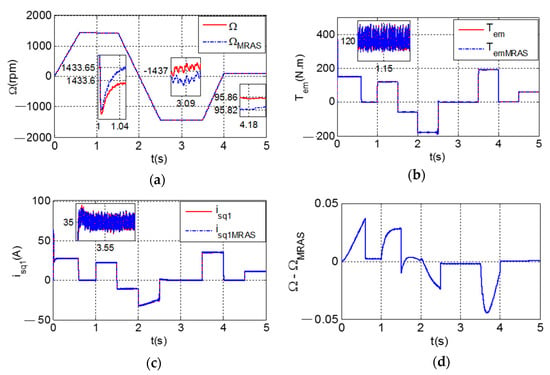
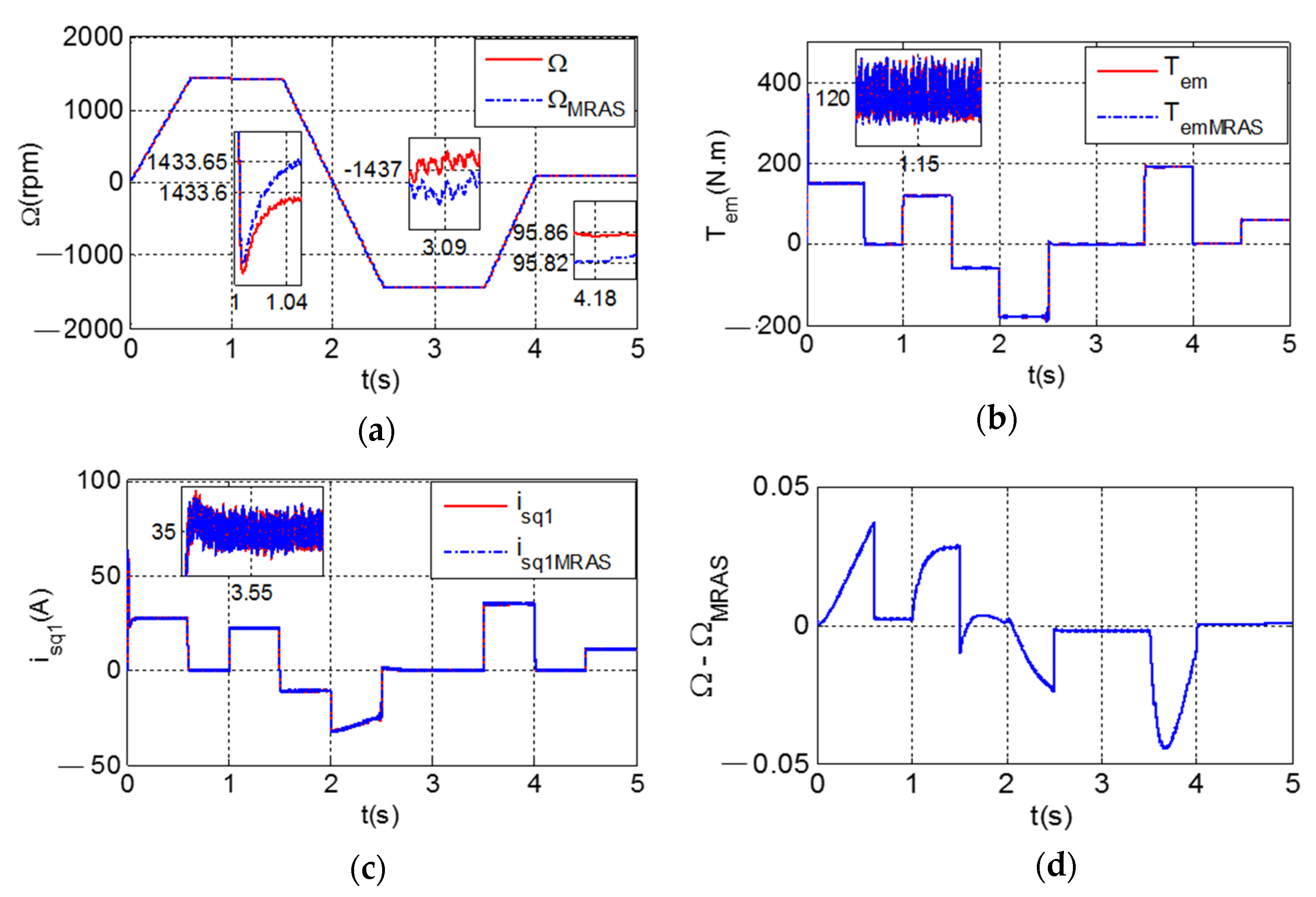
Figure 10 illustrates the dynamic performance of the DSIM drive under the RFOC-STSM control strategy, both with and without the MRAS-based speed estimator.
Figure 10.
Dynamic performance of the DSIM drive operating under the RFOC-STSM control strategy, with and without the integration of the MRAS observer: (a) rotor speed evolution; (b) electromagnetic torque response; (c) stator current component; and (d) speed tracking error.
Figure 10a shows the rotor speed response, where it can be clearly seen that the estimated speed closely follows the actual speed throughout the entire operating range, including acceleration, deceleration, low-speed operation, and speed reversal. A closer examination of the transient behavior reveals that the estimated speed converges rapidly during abrupt changes in the reference, with negligible overshoot and a short settling time. This highlights the high estimation accuracy of the MRAS observer. In addition, both configurations exhibit almost identical dynamic responses, which indicates that incorporating the MRAS estimator does not adversely affect the tracking performance of the drive. Notably, even in low-speed conditions, the observer maintains stable and precise estimation without oscillations or drift, confirming its robustness under demanding operating scenarios.
Figure 10b presents the electromagnetic torque response under the same operating conditions. It can be observed that the torque remains smooth and well-regulated for both configurations, with rapid stabilization following load disturbances. In addition, no significant increase in the torque ripple is introduced when the MRAS estimator is integrated, confirming that the proposed observer does not degrade the inherent robustness or disturbance rejection capability of the RFOC-STSM controller.
Similarly, Figure 10c illustrates the stator current response, where the currents remain smooth and well-controlled throughout all operating conditions. The stator currents stay stable and smooth, with quick recovery after load changes, showing good control performance. Moreover, the integration of the MRAS observer does not introduce additional oscillations or instability, ensuring that both the dynamic and steady-state performance characteristics of the drive are fully preserved.
In steady-state operation, the estimated speed closely matches the actual speed, with only very small deviations. Figure 10d further confirms this behavior, showing that the speed error remains tightly bounded within ±0.04 rad/s. This demonstrates the strong robustness of the observer against load changes and speed transients.
Overall, these results demonstrate that the integration of the adaptive MRAS with the RFOC-STSM controller provides accurate real-time speed estimation, superior disturbance rejection, and high robustness, making the proposed scheme highly suitable for precise control of Dual-Star Induction Machines in practical automation applications.
6. Configuration of the Proposed Control Approach on an FPGA
6.1. FPGA-Oriented Design of the RFOC-STSMC-MRAS Method Using XSG
The RFOC-STSMC-MRAS control strategy was developed using the Xilinx System Generator (XSG) within the Simulink environment, following a hardware-oriented design approach. Here, hardware-oriented implementation refers to fixed-point modeling and FPGA-compatible simulation rather than experimental execution on a physical FPGA platform.
FPGA-based solutions are particularly suitable for advanced nonlinear control because they offer parallel processing, low latency, and predictable execution capabilities that conventional DSP and microcontroller-based platforms often struggle to provide [36]. Accordingly, the full control scheme, including the Park and Clarke transformations, the STSMC speed controller, and the MRAS observer, was developed using XSG blocks configured in fixed-point and Boolean formats for FPGA-compatible implementation.
Since some functions, such as trigonometric operations, saturation, and integration, are not directly available in XSG, they were reconstructed using basic arithmetic and logical blocks (adders, delays, and logical operators). This ensures hardware compatibility while maintaining efficient resource usage and real-time capability in simulation [37,38].
XSG also supports co-simulation with Simulink, enabling the verification of internal signals and performance evaluation before synthesis in Vivado. This unified workflow simplifies the transition from control design to FPGA-oriented implementation and accelerates prototyping compared to conventional software-based approaches [39].
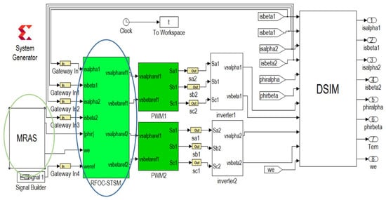
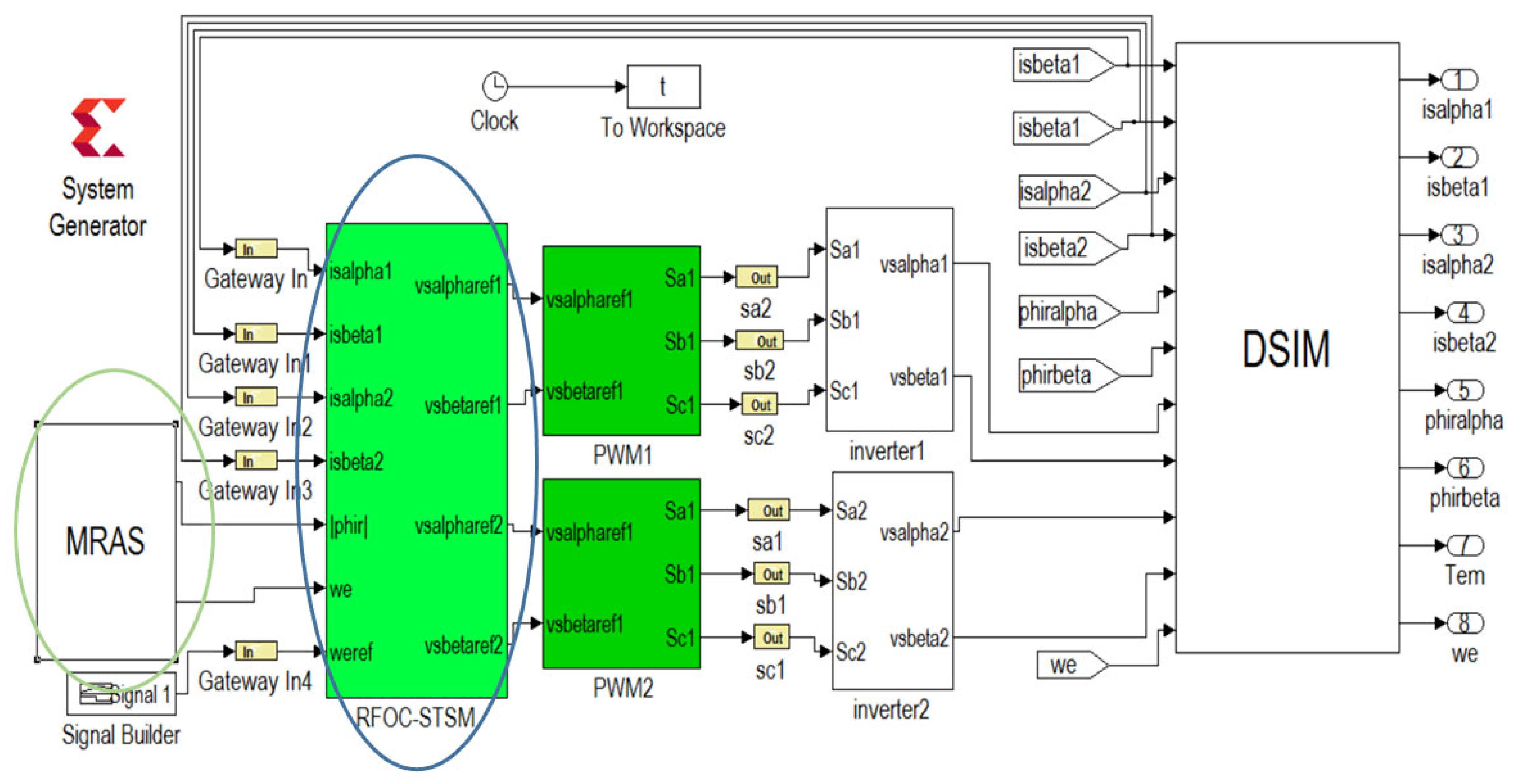
The proposed control architecture consists of several interconnected modules. Components not natively available in XSG—such as the Concordia transformation, the MRAS adaptation mechanism, and the STSMC—were specifically developed and integrated. Figure 11 presents the complete RFOC-STSMC-MRAS structure. In this setup, the controller and observer outputs drive the Dual-Star Induction Machine via PWM voltage signals generated in the XSG/Simulink environment.
Figure 11.
The block RFOC-STSM-MRAS under Xilinx System Generator.
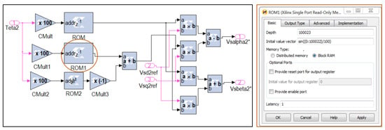
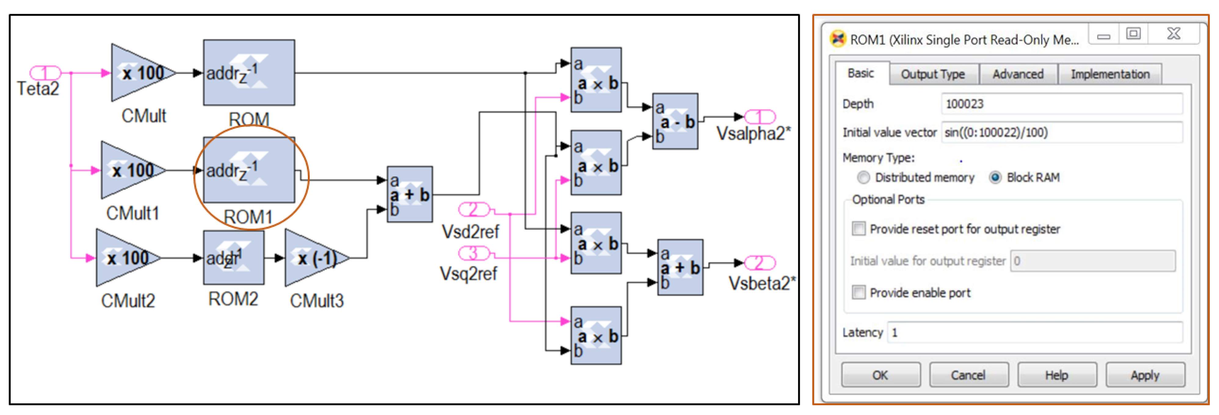
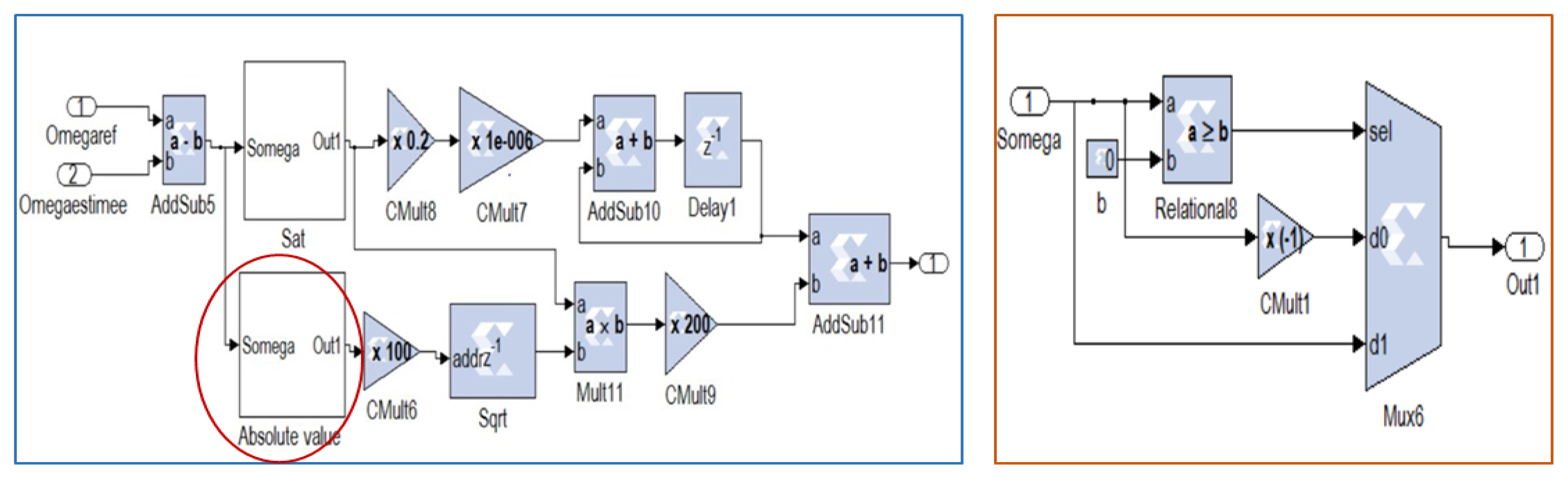
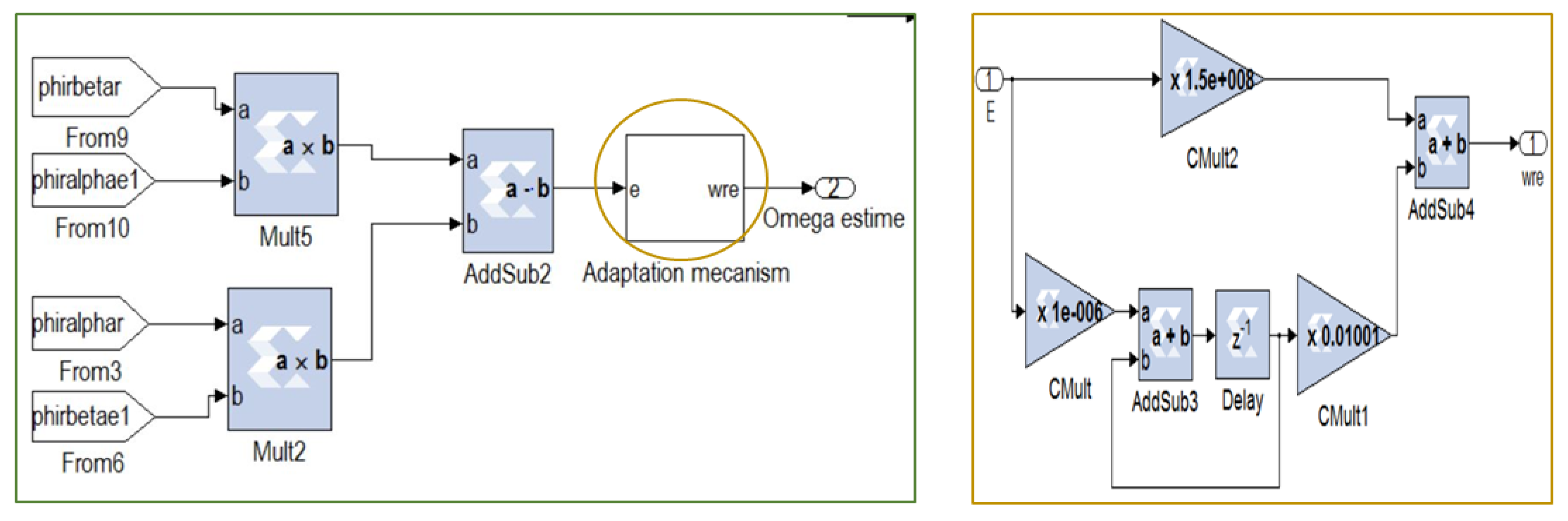
As shown in Figure 12, Figure 13 and Figure 14, each module operates based on predefined parameters that define its role within the control scheme. Careful tuning of these parameters is therefore essential to ensure stability, robustness, and good dynamic performance.
Figure 12.
XSG’s internal architectures of the Concordia.
Figure 13.
XSG’s internal architectures of the STSM controller.
Figure 14.
XSG’s internal architectures of the MRAS adaptation mechanism.
6.2. Implementation and Simulation Results of the RFOC-STSMC-MRAS Strategy Using Xilinx System Generator
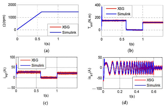
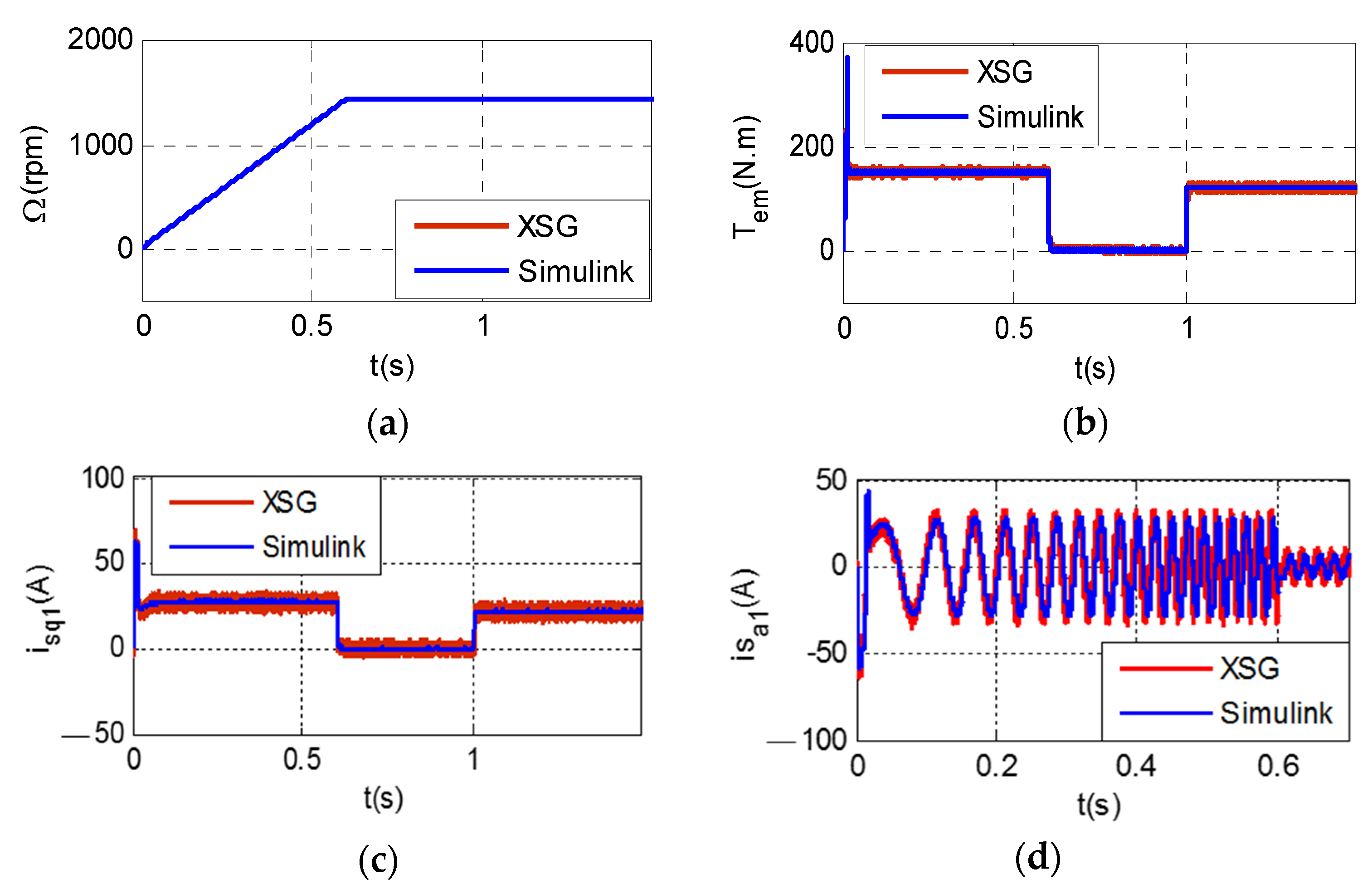
The implementation and simulation of the RFOC-STSMC-MRAS strategy using the Xilinx System Generator (XSG) produced results that are highly consistent with those obtained in the Simulink environment. This strong agreement validates both the accuracy of the developed control algorithm and the fidelity of its hardware-oriented modeling. XSG enabled the conversion of high-level control models into a fixed-point, logic-compatible structure suitable for FPGA-compatible implementation. This fixed-point realization allows for the efficient utilization of FPGA resources while ensuring deterministic real-time execution—a significant advantage over conventional software-based implementations.
A detailed comparison shows that the ripple levels observed in the XSG -based simulation environment closely follow those obtained in the Simulink simulation, with deviations remaining below 4% for both the current and torque. The dynamic motor characteristics were carefully analyzed, and both simulation environments exhibit closely matched transient and steady-state responses for rotor speed, torque, and phase currents. In particular, transient peaks, including initial torque and current overshoots, align closely in magnitude and timing, further confirming the accuracy and reliability of the XSG-based implementation relative to the Simulink model. These findings demonstrate that the hardware-oriented XSG modeling faithfully reproduces the simulated performance and that the proposed RFOC-STSM control combined with the adaptive MRAS observer maintains low ripple levels, ensuring stable and reliable operation for real-time applications. Figure 15 illustrates the comparative results, highlighting the excellent consistency between both environments.
Figure 15.
Comparison of DSIM simulation results under the RFOC-STSMC-MRAS approach using XSG and Simulink: (a) rotor speed evolution; (b) electromagnetic torque response; (c) stator current component; and (d) stator phase current .
7. Conclusions
This paper presented an RFOC-STSMC strategy integrated with an adaptive MRAS observer for sensorless control of Dual-Star Induction Machines. The proposed approach was thoroughly validated through comprehensive simulations and an FPGA-compatible simulation using the Xilinx System Generator (XSG) in a fixed-point modeling environment. Comparative analyses demonstrated that the RFOC-STSMC scheme significantly enhances the dynamic performance, reduces torque and current ripple, and provides improved robustness compared to conventional PI and sliding mode controllers.
The adaptive MRAS observer ensured accurate and stable rotor speed estimation without relying on mechanical sensors, thereby increasing system reliability and reducing implementation costs. Furthermore, the close agreement between Simulink and XSG simulation results confirms the consistency of the control algorithm and its suitability for FPGA-oriented implementation.
Overall, simulation results of the proposed control strategy represent a reliable and efficient solution for high-performance DSIM drives, making it particularly well suited for demanding industrial applications. Its FPGA-oriented design allows for efficient digital implementation, enabling fast prototyping within an FPGA-compatible framework. Moreover, the methodology provides a general framework that can be extended to other types of electrical machines, paving the way for broader applications in advanced industrial automation. Future work will focus on experimental validation on a physical FPGA platform, hardware resource optimization, and further extension to different machine types and embedded platforms.
Author Contributions
Conceptualization, F.Z.L. and A.B.R.; Methodology, F.Z.L.; Software, F.Z.L. and A.B.R.; Validation, F.Z.L., A.B.R. and A.K.; Investigation, F.Z.L. and A.B.R.; Writing—original draft preparation, F.Z.L.; Writing—review and editing, F.Z.L., A.B.R., and A.K.; Visualization, F.Z.L.; Supervision, A.K. All authors have read and agreed to the published version of the manuscript.
Funding
This research received no external funding.
Data Availability Statement
The original contributions presented in this study are included in the article. Further inquiries can be directed to the corresponding author.
Conflicts of Interest
The authors declare no conflicts of interest.
Appendix A. Parameters of the Dual-Star Induction Machine for Simulation (SI Units)
The analyzed Dual-Star Induction Machine operates at a rated voltage of 220 V and a nominal speed of 1437 rpm. It delivers a rated torque of 120 N·m, with stator currents of 2 × 19 A. The electrical parameters include stator resistances of 0.4 Ω and a rotor resistance of 0.096 Ω. The stator and rotor inductances are 82 mH and 8.9 mH, respectively, while the mutual inductances are 26.3 mH (stator–rotor) and 81.2 mH (stator–stator). From a mechanical standpoint, the machine is characterized by a moment of inertia of 0.6 kg·m2, a viscous friction coefficient of 0.8 N·m·s/rad, and two pole pairs.
References
- Mezaache, S.E.; Zaidi, E. Performance enhancement of dual-star induction machines using neuro-fuzzy control and multi-level inverters: A comparative study with PI controllers. Int. J. Robot. Control Syst. 2025, 5, 197–221. [Google Scholar]
- Nesri, M.; Nounou, K.; Sifelislam, G.; Benkhoris, M.F.; Azeddine, H.O. Hybrid flatness-based control of dual star induction machine drive system for more electrical aircraft. Power Electron. Drives 2024, 9, 50–62. [Google Scholar] [CrossRef] [Scilit]
- Nesri, M.; Benkadi, H.; Nounou, K.; Sifelislam, G.; Benkhoris, M.F. Fault-tolerant control of a dual star induction machine drive system using a hybrid fractional controller. Power Electron. Drives 2024, 9, 161–175. [Google Scholar]
- Zahraoui, Y.; Akherraz, M.; Ma’arif, A. A comparative study of nonlinear control schemes for induction motor operation improvement. Int. J. Robot. Control Syst. 2022, 2, 1–17. [Google Scholar]
- Bouguerra, Z. Comparative study between PI, FLC, SMC and fuzzy sliding mode controllers of DFIG wind turbine. J. Renew. Energy 2023, 26, 209–223. [Google Scholar] [CrossRef] [Scilit]
- Utkin, V.; Lee, H. Chattering problem in sliding mode control systems. In Proceedings of the International Workshop on Variable Structure Systems, Alghero, Italy, 5–7 June 2006. [Google Scholar]
- Latrech, F.Z.; Rhouma, A.B.; Khedher, A. Dual star induction machine driven by direct torque control using sliding mode speed controller. In Proceedings of the 2023 IEEE International Conference on Advanced Systems and Emergent Technologies (IC_ASET), Hammamet, Tunisia, 29 April–1 May 2023; IEEE: Piscataway, NJ, USA, 2023; pp. 1–5. [Google Scholar]
- Divandari, M.; Rezaie, B.; Noei, A.R. Speed control of switched reluctance motor via fuzzy fast terminal sliding-mode control. Comput. Electr. Eng. 2019, 80, 106472. [Google Scholar] [CrossRef] [Scilit]
- Reghioui, H.; Benguesmia, H.; Sadouni, R. DTC-SVM strategy of double star induction motor using sliding mode controller enhanced by fuzzy logic. Stud. Eng. Exact Sci. 2024, 5, e6045. [Google Scholar] [CrossRef] [Scilit]
- Prasad, K.A.; Unnikrishnan, A.; Nair, U. Fuzzy sliding mode control of a switched reluctance motor. Procedia Technol. 2016, 25, 735–742. [Google Scholar] [CrossRef] [Scilit]
- Krim, S.; Gdaim, S.; Mimouni, M.F. Robust direct torque control with super-twisting sliding mode control for an induction motor drive. Complexity 2019, 2019, 7274353. [Google Scholar]
- Elbarbary, Z.M.S.; Al-Harbi, O.K.; Al-Gahtani, S.F.; Irshad, S.M.; Abdelaziz, A.Y.; Mossa, M.A. Review of speed estimation algorithms for three-phase induction motor. MethodsX 2024, 12, 102546. [Google Scholar] [PubMed]
- Lazreg, M.H.; Bentaallah, A. Sensorless speed control of double star induction machine with five-level DTC exploiting neural network and extended Kalman filter. Iran. J. Electr. Electron. Eng. 2019, 15, 142–150. [Google Scholar]
- Lazreg, M.H.; Bentaallah, A. Speed sensorless vector control of double star induction machine using reduced order observer and MRAS estimator. In Proceedings of the 2017 5th International Conference on Electrical Engineering-Boumerdes (ICEE-B); IEEE: Boumerdes, Algeria, 2017; pp. 1–6. [Google Scholar]
- Benmiloud, I.; Kouzi, K.; Ameur, A. Sensorless vector control of dual star induction motor associated with fuzzy mutual–MRAS estimator in electric vehicle. Rom. J. Inf. Technol. Autom. Control 2023, 33, 135–146. [Google Scholar]
- Salehfar, H. DSP-based implementation of vector control of induction motor drives. In Handbook of Automotive Power Electronics and Motor Drives; CRC Press: Boca Raton, FL, USA, 2017; pp. 405–414. [Google Scholar]
- Prayogo, R.C.; Triwiyatno, A.; Riyadi, M.A. Field-oriented control implementation on BLDC motor controller with PI and SVPWM using STM32F103C8T6. J. Phys. Conf. Ser. 2023, 2622, 012025. [Google Scholar]
- Lai, C.K.; Ciou, J.S.; Tsai, C.C. The modelling, simulation, and FPGA-based implementation for stepper motor wide-range speed closed-loop drive system design. Machines 2018, 6, 56. [Google Scholar]
- Narjess, F.A.S.; Sofiene, S.B.G.; Ramzi, T.; Faouzi, M.M.; Badre, T.C.B. Direct torque control of an induction motor using Xilinx system generator: FPGA-based implementation. In Proceedings of the 14th International Conference on Sciences and Techniques of Automatic Control and Computer Engineering (STA); IEEE: Sousse, Tunisia, 2013; pp. 207–215. [Google Scholar]
- Boukadida, S.; Gdaim, S.; Mtibaa, A. A novel direct torque control for induction machine drive system with low torque and flux ripples using XSG. Int. J. Power Electron. Drive Syst. 2014, 4, 517. [Google Scholar] [CrossRef] [Scilit]
- Khedher, A.; Mimouni, M.F. Sensorless-adaptive DTC of double star induction motor. Energy Convers. Manag. 2010, 51, 2878–2892. [Google Scholar] [CrossRef] [Scilit]
- Latrech, F.Z.; Ben Rhouma, A.; Khedher, A. Sensorless vector control of dual star induction machine using sliding mode flux observer. In Proceedings of the 2023 IEEE International Conference on Advanced Systems and Emergent Technologies (IC_ASET)), Hammamet, Tunisia, 29 April–1 May 2023; IEEE: Piscataway, NJ, USA, 2023; pp. 1–5. [Google Scholar]
- Khelif, H.; Ben Hamed, M.; Dhaoui, M.; Lassaad, S. Indirect rotor field-oriented control of a dual star induction machine. In Proceedings of the 2017 International Conference on Green Energy Conversion Systems (GECS), Hammamet, Tunisia, 23–25 March 2017; IEEE: Piscataway, NJ, USA, 2017; pp. 1–6. [Google Scholar]
- Jnayah, S.; Moussa, I.; Khedher, A. IM fed by three-level inverter under DTC strategy combined with sliding mode theory. Electronics 2022, 11, 3656. [Google Scholar] [CrossRef] [Scilit]
- Sami, I.; Ullah, S.; Basit, A.; Ullah, N.; Ro, J.S. Integral super-twisting sliding mode based sensorless predictive torque control of induction motor. IEEE Access 2020, 8, 186740–186755. [Google Scholar]
- Benkhoris, M.F.; Gayed, A. Discrete sliding control technique of DC motor drives. In Proceedings of the Sixth IEEE International Conference on Power Electronics and Variable Speed Drives, Nottingham, UK, 23–25 September 1996. [Google Scholar]
- Levant, A. Robust exact differentiation via sliding mode technique. Automatica 1998, 34, 379–384. [Google Scholar] [CrossRef] [Scilit]
- Picó, J.; Picó-Marco, E.; Vignoni, A.; De Battista, H. Stability preserving maps for finite-time convergence: Super-twisting sliding-mode algorithm. Automatica 2013, 49, 534–539. [Google Scholar]
- Touati, Z.; Mahmoud, I.; Araújo, R.E.; Khedher, A. Fuzzy super-twisting sliding mode controller for switched reluctance wind power generator in low-voltage DC microgrid applications. Energies 2024, 17, 1416. [Google Scholar]
- Mirzaei, M.J.; Hamida, M.A.; Plestan, F.; Taleb, M. Super-twisting sliding mode controller with self-tuning adaptive gains. Eur. J. Control 2022, 68, 100690. [Google Scholar]
- Levant, A. Higher-order sliding modes, differentiation and output feedback control. Int. J. Control 1998, 76, 924–941. [Google Scholar]
- Korzonek, M.; Tarchala, G.; Orlowska-Kowalska, T. A review on MRAS-type speed estimators for reliable and efficient induction motor drives. ISA Trans. 2019, 93, 1–13. [Google Scholar] [CrossRef] [Scilit] [PubMed]
- Zerzeri, M.; Moussa, I.; Khedher, A. A software-implemented wind turbine emulator using a robust sensorless soft-VSI induction motor drive with STA-based flux observation and MRAS speed estimation. Automation 2026, 7, 30. [Google Scholar]
- Schauder, C. Adaptive speed identification for vector control of induction motors without rotational transducers. In Proceedings of the IEEE Industry Applications Society Annual Meeting; IEEE: Piscataway, NJ, USA, 1989; pp. 493–499. [Google Scholar]
- Tymerski, R. Optimizing Pole Placement Strategies for a Higher-Order DC-DC Buck Converter: A Comprehensive Evaluation. J. Power Energy Eng. 2025, 13, 47–69. [Google Scholar]
- Latrech, F.Z.; Ben Rhouma, A.; Khedher, A. FPGA implementation of a DTC SVM super-twisting sliding mode controller with adaptive stator flux observer for a double star induction motor. Stud. Inform. Control 2025, 34, 41–52. [Google Scholar] [CrossRef] [Scilit]
- Jnayah, S.; Ben Mahmoud, Z.; Guenenna, T.; Khedher, A. An improved DTC scheme based on common-mode voltage reduction for three-level NPC inverter in induction motor drive applications. Automation 2026, 7, 33. [Google Scholar]
- Latrech, F.Z.; Rhouma, A.B.; Khedher, A. FPGA implementation of a robust DTC-SVM based sliding mode flux observer for a double star induction motor: Hardware-in-the-loop validation. Microelectron. Reliab. 2023, 150, 115118. [Google Scholar]
- Moussa, I.; Khedher, A. A theoretical and experimental study of a laboratory wind turbine emulator using DC-motor controlled by an FPGA-based approach. Electr. Power Compon. Syst. 2020, 48, 399–409. [Google Scholar]

Disclaimer/Publisher’s Note: The statements, opinions and data contained in all publications are solely those of the individual author(s) and contributor(s) and not of MDPI and/or the editor(s). MDPI and/or the editor(s) disclaim responsibility for any injury to people or property resulting from any ideas, methods, instructions or products referred to in the content. |
© 2026 by the authors. Licensee MDPI, Basel, Switzerland. This article is an open access article distributed under the terms and conditions of the Creative Commons Attribution (CC BY) license.