


Highlights
- A functional diagram and a simulation model of a PID controller were developed, integrating fully virtual components: a Simatic S7-1500 PLC simulator, a SINAMICS S210 frequency converter Digital Twin, and a SIMOTICS S-1FK2 electric motor.
- Procedures for automatic tuning (autotuning) using the TIR algorithm were implemented and tested in a virtual environment, demonstrating stable system response to pulse, triangular, and random disturbance signals.
- The approach allows for the direct transfer of simulation results, configurations, and application software to physical Simatic S7 hardware, significantly streamlining the implementation of control systems.
- Implementation of Digital Twin technology for virtual commissioning makes it possible to apply control algorithms and research equipment operating modes without the risk of damaging real physical objects.
Abstract
The object of the research is the information interaction processes between the components of a simulation model of a PID controller based on Digital Twin technology. The problem addressed lies in the need to extend the functionality of various models when they are integrated into real control systems. The aim of the study is to develop a simulation model of a PID controller for electric-drive frequency-based control systems using Digital Twin technology. A concept for constructing a simulation model using unified hardware–software tools from Simatic S7 and Digital Twin technology is proposed. In this approach, virtual components of the simulation model are configured, parameterized, and programmed within the same engineering environment as the real ones. Projects developed based on simulation results of PID controllers provide the foundation for their implementation on real Simatic S7 hardware. The simulation model provides for integration and interaction of fully virtual components, including PLC, frequency converter, electric drive, SCADA, and communication environment. Procedures for parameterizing monitoring tools and for the automatic tuning of PID controller parameters according to the chosen strategy were implemented, which enabled a clear graphical evaluation of transient processes under different operating modes of the simulation model. The response of the PID controller to periodic and random disturbance signals within up to100% of the control range was tested.
1. Introduction
In the current conditions of intensive development of industrial automation and digitalization of production processes, the role of automated control systems for technological objects (ACS TO) is growing as a key element in ensuring the efficiency, reliability and safety of the functioning of complex technical systems. Increasing requirements for the quality of regulation, energy efficiency, and adaptability of such systems necessitate the use of new approaches to the design, configuration, and verification of regulators. At the same time, the creation of simulation models based on the Digital Twin is an integral part of a comprehensive approach during the design, creation, implementation, operation, and support of ACS TO [1,2,3,4].
One of the promising areas of development of ACS TO is the use of simulation models of regulators, which allow for the research of the dynamic properties of control systems in different operating modes without interfering with the real technological process [5,6,7].
The use of modern information technologies, intelligent data analysis algorithms, and modeling environments significantly expands the capabilities of simulation modeling and increases its significance and practical value in line with the concept of “Industry 4.0” [8,9,10]. The use of smart controllers and threshold vibration indicators to indicate node degradation and reduced productivity has been demonstrated in applied research in the mining industry [11,12].
In the above context, the Digital Twin technology attracts attention, involving the creation of virtual components of the ACS TO that operate in a mode close to real time. The integration of simulation models of regulators in the Digital Twin creates new prospects for optimizing control algorithms, predicting system behavior, conducting virtual experiments, and supporting engineering decision-making throughout the life cycle of the controlled object.
Particularly relevant is the direction of expanding the functionality, maximum compliance, and binding of fully virtual components of simulation models to real hardware, software, and technological equipment. The implementation of such a concept should ensure the compatibility and consistency of information processes for direct transfer of the results of simulation modeling of configurations, algorithms, and application software into working designs of the ACS TO [13,14].
In this regard, the development, testing, and research of information processes of interaction between components of simulation models of ACS TO based on modern information technologies and the Digital Twin technology is an urgent scientific and practical task.
In some research [15], a practical implementation of a behaviorally oriented Digital Twin for an electropneumatic actuator based on the PLC Simatic S7-1500 (Siemens AG, Munich, Germany) was performed. A comparative analysis of three models of a digital Digital Twin with different levels of physical reliability was developed and conducted. The methodology includes geometric modeling in “NX Mechatronics Concept Designer” (Siemens AG, Munich, Germany), behavioral simulation in “SIMIT” (Siemens AG, Munich, Germany), and PLC emulation in “PLCSIM Advanced” (Siemens AG, Munich, Germany). The results demonstrate high accuracy of actuator dynamics reproduction (correlation with experimental data), flexibility for testing various control strategies and the possibility of virtual modeling without physical equipment. The work has significant practical value for industrial automation but is limited to pneumatic systems without adaptation for real-time operation.
In the study [16], a Digital Twin is presented for the identification of three-phase inverter and sensor parameters, which are directly related to frequency converters. A virtual model is proposed for the estimation of PID controller parameters. From the point of view of frequency control, the model accounts for the inverter’s frequency characteristics (harmonics, impedance). The methodology includes modeling the inverter dynamics, taking into account sensor errors. The results demonstrate accurate identification for improved control (error <5%). The concept is the integration of Digital Twin with sensor signals. Practical significance is the application in power systems for diagnostics, with the possibility of implementation on Simatic S7 hardware. The validation problems on real hardware are unresolved.
The authors of [17] proposed a Digital Twin for frequency control in hydrogen technological installations (electrolyzers, fuel cells, and H2 storage) that use frequency converters. Dynamics modeling was performed in MATLAB-Simulink, V R2020a (MathWorks, Natick, MA, USA) with a PI loop for power control. The model provides frequency control at a frequency of 50 Hz. The methodology includes validation of Digital Twin with real frequency converters (response time 2.2–2.8 s.). Unsolved problems—simulation models based on MATLAB-Simulink require significant complication for their possible transfer to projects with real hardware and software.
In [18], a methodology for building a Digital Twin for logistics tasks of conveyor transportation of products using frequency control based on the “Industry 4.0” concept was proposed. A production line was modeled in the Tecnomatix environment connected to the PLC Simatic S7-1200 (Siemens AG, Munich, Germany) via OPC UA. The model simulates frequency control to optimize conveyor speed. At the same time, the unsolved problems include the lack of a full-fledged Digital Twin frequency converter. In the study [19], an approach to modeling production equipment based on the integration of Digital Twin IIoT, and VR is proposed to ensure real-time synchronization between the physical system and the Digital Twin close to real time. Experimental results confirm the practical effectiveness of the proposed solution for monitoring and analyzing control processes. The combination of Edge architectures with a Digital Twin for IIoT data processing, where PID optimization is possible through ML (Machine Learning) (MathWorks, Natick, MA, USA), is considered. The work demonstrates the advantages of Edge, but is limited to laboratory conditions.
The publication [20] presents the results of the study of Digital Twin for detecting unauthorized interventions in industrial SCADA systems interacting with PLC Simatic S7-1200 with PID controllers. The results of modeling based on a Digital Twin for the simulation of anomalies and testing of PID controllers in a virtual environment are presented. The work has practical significance for cybersecurity, but the optimization of PID controller parameters remains unresolved.
In [21], the cloud platform “PROSIM” is presented—software for simulation of technological processes (Fives ProSim S.A.S., Labège, France) for educational tasks in the direction of automation of technological processes based on the simulator of the PLC Simatic S7-1200 and the software platform “TIA Portal” (Siemens AG, Munich, Germany), which are integrated with “Factory I/O”—a software simulator of industrial automation (Real Games AS, Gondomar, Portugal). The work has practical significance for modeling PID controllers but is limited to educational tasks and lacks virtual components for frequency control of the electric drive.
Researchers [22] proposed a methodology for tuning a PID controller using Digital Twin” for dynamic systems. The structure and mechanism of the Digital Twin model for optimizing a PID controller based on virtual simulation with parameter estimation (Kp, Ki, Kd) and optimization by stability criteria are described. The methodology includes integration with PLC (in particular, Simatic S7) for data exchange between the physical system and the model in real time. The results obtained provide a 20–30% reduction in tuning time. However, the study is limited to laboratory conditions without full integration of ML for optimizing PID controllers.
In [23], the implementation of a digital PID controller based on the PLC Simatic S7-300 is considered. An adaptive approach to temperature control problems is proposed. The work has practical significance for industrial systems, but the problem of building a simulation model of a PID controller with fully virtual components based on the Digital Twin technology remains unsolved. The authors of [24] developed a Digital Twin for a PID controller on an FPGA with fixed accuracy and the possibility of integration into the PLC Simatic S7. The paper provides a comparative analysis of the accuracy and speed parameters of the PID controller and demonstrates the advantages of such an implementation for real-time systems. The study has practical significance for embedded systems, but uses separate hardware without full virtualization of the Digital Twin components.
In [25], an integrated computational methodology for energy-efficient configuration of industrial electric drives using Digital Twin and Virtual Commissioning (VC) is proposed. The main focus of the work is on the creation of parameterized component models based on manufacturer data, which are implemented in a commercial simulation environment and integrated into the industrial Virtual Commissioning platform. This allows for the assessment of energy consumption, losses, and efficiency of electric drives at an early stage of design. The validation of the proposed methodology was performed on two experimental stands with conveyors, where the simulation results were compared with real tests. The study showed that such an integration of Digital Twin and Virtual Commissioning allows for the quantitative assessment of trade-offs between minimizing energy consumption and maximizing efficiency across various production solutions. The methodology has practical significance for planning energy-efficient solutions for industrial electric drive systems. At the same time, the practical implementation of the method is relatively complex, which is due to the need to integrate not completely virtual components, take into account the operating modes of the model, and perform a significant number of experimental tests to determine the optimal parameters of the PID controller.
In the paper [26], a method of dynamic tuning of the PID controller in real time for industrial automation systems based on the PLC Simatic S7-300 and the SINAMICS G120C frequency converter (Siemens AG, Munich, Germany) is considered. The proposed approach is based on the hybrid PSO-MANFIS algorithm, which combines PSO (Particle Swarm Optimization) and MANFIS (Multiple Adaptive Neuro-Fuzzy Inference System). PSO is used to globally search for optimal controller coefficients (Kp, Ki, and Kd), while MANFIS adapts them during operation of the controlled object based on the current error and its change. Data exchange between the PLC and the optimization environment is carried out via the OPC (Open Platform Communications) server—a standard in industrial automation systems. Experimental results indicate a reduction in the transient time, a decrease in the root mean square error (RMSE), and a practically complete absence of overshoot compared to classical static methods of tuning PID controllers. Integration of the MATLAB-Simulink environment with industrial automation systems via an OPC server allows the use of advanced MATLAB optimization algorithms to determine the optimal parameters of an industrial PID controller. Such an interface MATLAB ↔ OPC ↔ PLC ↔ Frequency Converter provides continuous data exchange, real-time monitoring, data analysis, and complex computational methods. At the same time, the approach is characterized by increased implementation complexity, dependence on the quality of measurements and stability of communications, as well as lower controller interpretability. In general, the work confirms the prospects of intelligent adaptive methods for dynamic tuning of PID controllers in industrial control systems, provided that a compromise is made between control quality and the practical complexity of implementation.
Analysis of research results [15,16,17,18,19,20,21,22,23,24,25,26] allows us to conclude that during the creation of modern control systems for technological objects, modeling methods, tools, and technologies are widely used, both for individual components of such systems and for technological processes as a whole. At the same time, special attention is paid to the creation and integration of Digital Twin into various types of control system models, which significantly increases the efficiency of design processes. This applies, first of all, to design time, quality of design solutions, cost of design and prototyping, reliability, flexibility, and scalability. In addition, the results of the analysis indicate that for practical engineering, it is precisely imitation models based on Digital Twin that play an important role, as they are the most approximate in functionality and compatible with real hardware and software tools of ACS TO.
At the same time, when creating and using simulation models, it is necessary to comprehensively address individual scientific and technical problems related to expanding functionality, standardizing and unifying design procedures, and studying information processes in the interaction between components.
From the analysis of the research results [15,16,17,18,19,20,21,22,23,24,25,26] it also follows that when creating and integrating simulation models into projects, the hardware and software tools Simatic S7 [15,18,20,21,22,23,24,25,26] and MATLAB-Simulink [17,19] are relatively widely used. In simulation models based on Simatic S7 equipment, the virtual simulators PLCSIM for the PLC Simatic S7-1200 series are used as a Digital Twin, which emulate the PLC logic and support separate virtual communications. However, only PLCSIM Advanced supports the functionality for PID controllers of the PLC Simatic S7-1500 series. At the same time, in studies [15,18,20,21,22,23,24,25,26], the problem of creating and integrating full-fledged Digital Twin frequency converters into the simulation model, as the main and most complex components of control systems for technological objects, remains unresolved.
In this regard, the development, integration into working projects, testing, and research of information processes of interaction between components of simulation models of regulators based on unified hardware and software tools and Digital Twin technology is an urgent scientific and practical task.
The research hypothesis is formulated as follows. A concept is proposed for constructing a PID controller simulation model for frequency drive control systems based on unified Simatic S7 hardware and software and Digital Twin technology. The implementation of this concept will enable the preliminary determination of PID controller parameters using a selected strategy and the investigation of the operating regimes of electric-drive control systems for industrial plants, with direct correlation to physical Simatic S7 hardware. This approach assumes that the virtual components of the simulation model are configured, parameterized, and programmed in the same manner as physical components within a common engineering environment. Consequently, the simulation results for PID controllers with modified parameters serve as a foundation for their transfer to real Simatic S7 hardware assets.
The comprehensive solution to the stated objectives requires the application of structural and functional design methods, control system simulation modeling techniques, control theory and practice of control engineering, and methodologies for the development of algorithms and application software.
Purpose and objectives of the study. The purpose of the study is to develop a simulation model of a PID controller for frequency control systems of an electric drive based on the Simatic S7 hardware and software and Digital Twin technology.
This will enable preliminary testing and determination of the parameters of components of electric drive control systems for technological objects.
To achieve the set goal, it is necessary to solve the following tasks:
- Develop a functional diagram of a simulation model of a PID controller;
- Develop a design and components of a simulation model of a PID controller;
- Implement procedures for automatically determining the coefficients of a simulation model of a PID controller;
- Test the reaction of the simulation model of a PID controller to disturbance signals.
2. Materials and Methods
The object of the study is the information processes of interaction between the components of the simulation model of the PID controller for frequency control systems of the electric drive based on the Digital Twin technology.
A Digital Twin is a virtual representation of a physical object, system, or process that leverages real-world data for simulation, monitoring, and analysis. “Digital Twins” enable the emulation of physical asset operation, facilitating the identification of errors and potential issues during the design phase, the prediction of functionality, the investigation of operating regimes, and the optimization of industrial process control. A Digital Twin constitutes a virtual component in the form of a 3D model, a mathematical or simulation model, or an integrated combination of these elements. “Digital Twins” are integral to the Industry 4.0 and Industry 5.0 paradigms, representing a key frontier in the advancement of industrial engineering, information technology, and scientific research.
The following assumptions are made: the functionality of the virtual components of the simulation model of the PID controller based on Digital Twin technology may have some limitations compared to the real components (as defined in the technical documentation and regulations of the hardware and software manufacturer) [27].
The following simplifications are made in the work: the simulation model of the PID controller based on the Digital Twin technology is developed for certain types of Simatic S7-1500T PLCs, SINAMICS S210 PN 3.5 kW frequency converter, SIMOTICS S-1FK2 3.3 kW electric drive, at a nominal speed of 3000 1/min.
In the process of developing a simulation model of a PID controller based on the functional block of the PID-Compact_V3 technological object, the formula and corresponding coefficients of the controller from the technical documentation of the manufacturer of hardware and software Simatic S7 [28] were used:
Table 1 provides the definition of symbols in Equation (1) and corresponding parameters of the functional block of the PID-Compact_V3 technological object. Parameters with the prefix “Retain” refer to those stored in the non-volatile memory of the PLC, and without the prefix—to current variables.
Table 1.
Symbols in equation (1) and corresponding parameters of the functional block of the technological object “PID-Compact_V3”.
To analyze the results of testing the simulation model of the PID controller, various disturbance signals were applied (periodic pulse, periodic triangular shape, and pulse from a random number generator).
In the process of developing a simulation model of the PID controller based on the Digital Twin technology for control systems, the following hardware and software tools were used:
- PLC (Programmable Logic Controller CPU 1511T-1 PN V4.0), (Siemens AG, Munich, Germany) [29];
- FC (Frequency Converter SINAMICS S210 PN), (Siemens AG, Munich, Germany) [30];
- Motor (SIMOTICS S-1FK2), (Siemens AG, Munich, Germany) [31];
- Communication Network (PROFINET/Industrial Ethernet);
- TIA Portal V20 tool package, (Siemens AG, Munich, Germany) [32];
- SCADA WinCC Unified V20, (Siemens AG, Munich, Germany) [32];
- SINAMICS FC integration software package in TIA Portal V20 projects (StartDrive Advanced V20), (Siemens AG, Munich, Germany) [33];
- Virtual simulator for PLC S7-1500 (S7-PLCSIM Advanced V8.0), (Siemens AG, Munich, Germany) [34];
- Software package for generating and parameterizing “Digital Twins” SINAMICS S210 PN with integrated SIMOTICS S-1FK2 (DriveSim Engineer V2.1), (Siemens AG, Munich, Germany) [35].
3. Results
3.1. Development of a Functional Diagram of a Simulation Model of a PID Controller
The simulation model of the PID controller based on the hardware-software tools of Simatic S7 technology and the Digital Twin is presented as a functional diagram (Figure 1).
Figure 1.
Functional diagram of the simulation model of the PID controller based on the Simatic S7 hardware-software toolset and Digital Twin technology.
The functional diagram includes the following components:
- TIA_Portal_V20: an engineering environment for control systems design;
- PLC_Simulator: a virtual PLC simulator capable of integrating PID controller functionality;
- Digital Twin: a virtual frequency converter (FC) capable of integrating a virtual electric drive (M);
- PID controller signals: “Setpoint,” “Input,” and “Output.”
When creating the simulation model, the following tasks and procedures must be developed:
- Developing the functional diagram of the PID controller simulation model, considering the specifics of the virtual communication environment.
- Developing the project and components of the PID controller simulation model (configuring, parameterizing, establishing the communication environment, developing application software for the PLC_Simulator, generating the Digital Twin of the frequency converter (FC) with an integrated electric drive (M) possessing specified parameters, and organizing the interaction between the virtual components of the model).
- Implementing the procedure for the automatic determination of the PID controller simulation model coefficients (for its initiation and successful completion, a prerequisite is the correct execution of the preceding tasks and procedures, taking into account the functional characteristics of the virtual model components). This procedure is functional both for real equipment and for simulation modeling tasks based on the hardware-software tools of Simatic S7.
- Creating test imbalance signals at the “Setpoint” input, testing the response of the PID controller simulation model, and organizing the output of the simulation results in the form of time trends using SCADA tools.
A simulation model of a PID controller based on Simatic S7 hardware and software and Digital Twin technology provides for a comprehensive integration and interaction of fully virtualized components, including a communication environment:
- Virtual PLC simulator Simatic S7-1500 (PLCSIM Advanced V8.0);
- Digital Twin Frequency Converter SINAMICS S210 PN with an integrated electric drive “SIMOTICS S-1FK2” (created and parameterized in the DriveSim Engineer V2.1 environment);
- Siemens Virtual Ethernet Adapter (for communication with PLCSIM Advanced V8.0);
- SINAMICS DriveSim Virtual Network Interface (for communication with the Digital Twin frequency converter SINAMICS S210 PN);
- S7-PLCSIM Advanced Virtual Switch (for interaction between network virtual components);
- Software functional block “PID_Compact” for implementing the PID controller algorithm;
- TIA Portal V20 (industrial platform for creating projects, configuring and parameterizing hardware, setting up the communication environment, developing application software, and visualizing and interacting with virtual components of process control systems;
- SINAMICS StartDrive Advanced V20 (software package for integrating Frequency Converter into TIA Portal projects with configuration, parameterization, programming, diagnostics, and commissioning functions);
- SCADA WinCC Unified V20 (a web-based SCADA system for Human Machine Interface (HMI) applications).
Figure 2 shows a functional diagram of the simulation model of the PID controller based on Simatic S7 hardware and software and Digital Twin technology.
Figure 2.
Functional diagram of the simulation model of the PID controller based on Simatic S7 hardware and software and Digital Twin technology.
PLCSIM Advanced V8.0 interacts with the SINAMICS S210 PN Digital Twin with the integrated SIMOTICS S-1FK2 electric drive via the virtual Siemens Virtual Ethernet Adapter, S7-PLCSIM Advanced Virtual Switch, and SINAMICS DriveSim Virtual Network Interface. In this case, bidirectional data exchange occurs via the SIEMENS_telegram_105 communication protocol [14].
The TIA Portal V20 tool package is used to configure, parameterize, debug the communication environment, and develop application software for the hardware part of the simulation model based on the PLC Simatic S7-1500. The SINAMICS StartDrive Advanced V20 extension package integrated into TIA Portal V20 provides functionality for parameterizing the SINAMICS S210 PN Digital Twin, automatically determining the coefficients of PID controller, testing, and commissioning the FC SINAMICS S210 PN. The software function block “PID_Compact” directly implements the PID controller algorithm based on the defined “PID Parameters”. The PID controller parameters can be automatically calculated within the TIA Portal engineering environment or entered manually.
The hardware and software parameters for the functional diagram shown in Figure 1 have been refined:
- PLC (CPU 1511T-1 PN FW 4.0—Technology CPU: work memory 450 KB code and 1.5 MB data; 6 ns bit operation time; PROFINET interface RT/IRT with 2 ports; FW 4.0, article 6ES7511-1TL03-0AB0);
- Virtual PLC simulator Simatic S7-1500 (PLCSIM Advanced V8.0, article 6ES7823-1FE06-0YA5);
- Digital Twin Frequency Converter (SINAMICS S210 PN, FW 6.4, article 6SL5310-1BE13-5xFx) with an integrated electric drive (SIMOTICS S-1FK2, article 1FK2106-6AF0x-xDxx)—created and parameterized in the DriveSim Engineer V2.1 environment, article 9SV1310-4AA00-0AA0);
- TIA Portal V20 Upd 4 (industrial platform for creating projects, configuring and parameterizing hardware, setting up the communication environment, developing application software, and visualizing and interacting with virtual components of process control systems, article 6ES7822-1AA24-0YA5);
- Software technology object PID (PID_Compact V3.0) for implementing the PID control algorithm (integrated to TIA Portal);
- SINAMICS StartDrive Advanced V20 SP1 (software package for integrating Frequency Converter into TIA Portal projects with configuration, parameterization, programming, diagnostics and commissioning functions, article 6SL3072-4LA02-0XG5);
- SCADA WinCC Unified V20 Upd 4 (WinCC Unified PC (10k) ES, article 6AV2153-2FB02-4LA5).
Thus, the functional diagram of the PID controller simulation model, based on the unified hardware and software tools of Simatic S7 and Digital Twin technology, serves as the basis for developing individual virtual components of the simulation model.
3.2. Development of the Design and Components of the PID Controller Simulation Model
Before the start of development, the following parameters of the PID controller simulation model were determined:
- The PID controller simulation model is being developed to study the operating modes, testing, and commissioning of unified hardware and software tools of the Simatic S7 control systems;
- Development environment: industrial software platform TIA Portal V20 with an integrated SINAMICS StartDrive Advanced V20 extension package;
- The model is developed on the basis of the technological PLC Simatic S7-1511T-1 PN;
- The algorithm and control parameters are implemented in a virtual PLC simulator, which exchanges data with the Frequency Converter SINAMICS S210 PN via the communication protocol “SIEMENS_telegram_105”;
- Digital Twin SINAMICS S210 PN with integrated SIMOTICS S-1FK2 electric drive is generated and parameterized using the DriveSim Engineer V2.1 software package;
- Output power of SINAMICS S210 PN is 3.5 kW while the nominal power of integrated SIMOTICS S-1FK2 electric drive is 3.3 kW;
- Nominal speed of SIMOTICS S-1FK2 electric drive is 3000 1/min.
To develop a simulation model of the PID controller, test disturbance signals are created:
- Pulse disturbance signal (amplitude change 0–100% depending on the control range 0–3000 1/min, period 10 s, 50% duty cycle);
- Periodic disturbance signal of triangular shape (amplitude change 0–100% depending on the control range 0–3000 1/min, period 10 s);
- Disturbance signal from random number generator (change in values 0–100% depending on the control range 0–3000 1/min, duration of value 5.0 s).
3.2.1. Development of Components of the PID Controller Simulation Model at the Technological PLC Level
Development of the project and components of the PID controller simulation model at the technological PLC level includes the following stages:
- Creation of the simulation model project in the TIA Portal V20 environment;
- Configuration and parameterization of the hardware of the simulation model;
- Development and parameterization of the communication environment of the simulation model;
- Development of the application software of the PID controller simulation model (software blocks for controlling the operating modes of the technological PLC, the “PID_Compact” controller software block, software blocks for disturbance signals, software blocks for the measuring loop and feedback).
Figure 3 shows the result of creating the project, configuring, parameterizing the hardware and communication environment of the PID controller simulation model in the TIA Portal V20 design environment [36].
Figure 3.
The result of creating a project, configuring, and parameterizing the hardware and communication environment of the PID controller simulation model in the TIA Portal V20 environment.
The project components displayed in the TIA Portal V20 “Network view” editor are the following (Figure 3):
- PLC_1 CPU 1511T-1 PN;
- FC Drive unit_1 S210 PN with an integrated SIMOTICS S-1FK2 electric drive;
- SCADA WinCC UnPCRT deployed on the basis of a SIMATIC PC Station;
- PROFINET/Industrial Ethernet.
Figure 4 shows the result of parameterizing and operating in online mode of the “PID_Compact” software instruction of the simulation model based on automatically determined PID controller coefficients [28].
Figure 4.
The result of parameterizing and operating in “online” mode of the “PID_Compact” software instruction of the simulation model based on automatically determined PID controller coefficients.
Figure 4 displays, in “online” mode, the project tree (DCE_V2.1_proj_170426_1—on the left), the software instruction (PID_Compact—in the center), and the catalog of technology instructions (Technology → PID Control → Compact PID → PID_Compact → Universal PID controller with integrated tuning V3.0).
In the process of developing the application software for the PID controller simulation model, the following main parameters of the “PID_Compact” block were determined:
- Input “Setpoint”: PID controller setpoint in the range of 0–3000 1/min for the variable-frequency drive (the reference value relative to which PID control is performed);
- Input “Input”: 0–3000 1/min (feedback signal value in the PID controller simulation model, associated with the “ActualSpeed” signal);
- Input “ManualValue”: 0–100% (output signal value of “PID_Compact” in “Manual mode”);
- Input “Mode”: (“Inactive”, “Pretuning”, “Fine tuning”, “Automatic mode”, “Manual mode”);
- Output “Output”: 0–100% (corrective signal value at the output of “PID_Compact” in “Automatic mode”).
Figure 5 shows the results of parameterization and operation in “online” mode of the program blocks of the disturbance signals for the simulation model of the PID-controller “LGF_TriangleCI_DB” and “LGF_RandomRange_Real” [37].
Figure 5.
The result of parameterization and operation in “online” mode of the program blocks of the disturbance signals for the simulation model of the PID-controller “LGF_TriangleCI_DB” and “LGF_RandomRange_Real”.
The following main parameters of the “LGF_TriangleCI_DB” block are defined:
- Input “amplitude”: ±1500.0 (range of amplitude change of the periodic triangular disturbance signal, which corresponds to 0–100% depending on the control range 0–3000 1/min) (Figure 5);
- Input “period”: 10,000 ms (period of the triangular disturbance signal) (Figure 5);
- Input “OB_CyclicInterrupt_1”: 31 (number of “CyclicInterrupt [OB31]” in which “LGF_TriangleCI_DB” is executed);
- Output “value”: ±1500.0 (signal at the output of “LGF_TriangleCI_DB”).
The following main parameters of the “LGF_RandomRange_Real” block are defined:
- Input “minValue”: −1500.0 (the minimum value of the deviation signal from the random number generator, relative to the setpoint signal “Setpoint” = 1500 1/min);
- Input “maxValue”: +1500.0 (the maximum value of the deviation signal from the random number generator, relative to the setpoint signal “Setpoint” = 1500 1/min);
- Output «Ret_Val»: ±1500.0 (signal at the output «LGF_RandomRange_Real»).
The pulse disturbance signal was parameterized in a similar way (range of amplitude change 0–100% depending on the control range 0–3000 1/min, period 10 s, 50% duty cycle).
3.2.2. Development of Components of the Simulation Model of the PID Controller at the Level of the Digital Twin SINAMICS S210 PN
Development of components of the simulation model of the PID controller at the level of the Digital Twin SINAMICS S210 PN includes the following stages:
- Configuration and parameterization of the Frequency Converter SINAMICS S210 PN with the integrated electric drive SIMOTICS S-1FK2 using the TIA Portal V20 tool package and the SINAMICS StartDrive Advanced V20 extension package;
- Generation of the Digital Twin SINAMICS S210 PN with the integrated electric drive SIMOTICS S-1FK2 using the DriveSim Engineer V2.1 software;
- Establishing a communication link between the PLCSIM Advanced V8.0 virtual simulator and the SINAMICS S210 PN Digital Twin based on the Siemens Virtual Ethernet Adapter and the SINAMICS DriveSim Virtual Network Interface based on the SIEMENS_telegram_105 communication protocol.
Figure 6 shows the procedure for creating a Digital Twin of a SINAMICS S210 PN with an integrated SIMOTICS S-1FK2 electric drive.
Figure 6.
Procedure for creating a Digital Twin of SINAMICS S210 PN with an integrated SIMOTICS S-1FK2 electric drive.
After the configuration and parameterization procedures of the Frequency Converter SINAMICS S210 PN with the integrated SIMOTICS S-1FK2 electric drive, the procedure for generating the Digital Twin of SINAMICS S210 PN is performed using the DriveSim Engineer V2.1 software. As a result, the Digital Twin of SINAMICS S210 PN is created in the form of a DriveSim instance object with the corresponding ID, Name, and IP address [14]. At the same time, the Digital Twin can interact with other virtual components of the PID controller simulation model via virtual network adapters (Figure 2) and support a built-in Web server for setting operating modes, monitoring information processes and parameterizing SINAMICS S210 PN. The feature and advantage of the above implementation of the simulation model is the binding of virtual components to unified Simatic S7 hardware and software tools, which makes it possible to directly transfer previously tested projects to real hardware Simatic S7 control systems.
3.2.3. Development of the PID Controller Simulation Model Components at the Communication Environment Level
During the development and testing of the simulation model, the following parameters of the main cycle of the virtual CPU 1511T-1 PN FW4.0 were recorded under active and inactive communication with the SINAMICS S210 PN Digital Twin (Table 2).
Table 2.
Parameters of the main program cycle of the virtual CPU 1511T-1 PN under different communication modes with the SINAMICS S210 PN Digital Twin.
“Virtual Time Scaling” for PLCSIM Advanced was not applied.
The interaction between the virtual components of the simulation model took place under the following parameters of the PROFINET I/O System (100) communication bus:
- The communication parameters at the SINAMICS S210 PN level are presented in Figure 7;
- The communication parameters at the CPU 1511T-1 PN level are presented in Figure 8.
Figure 7.
Communication parameters at the SINAMICS S210 PN level.
Figure 8.
Communication parameters at the PLC level.
The PLC cyclic interrupt organization block MC_Servo [OB91] handles the communication between the virtual SINAMICS S210 PN and the CPU 1511T-1 PN with a “Send clock = 4.0 ms” and a “Cycle time = 32 ms”. Meanwhile, the cyclic interrupt time of the “CyclicInterrupt [OB30]” organization block, in which the “PID_Compact” software instruction is executed, was 10 ms during testing.
3.3. Implementation of Procedures for Automatic Determination of Coefficients of the PID Controller Simulation Model
The procedure for automatic determination of coefficients of the PID controller simulation model in the toolkit “Technology objects” → “PID_Compact_1” → “Commissioning” includes the following [28,38]:
- Parameterization of the toolkit for monitoring and automatic determination of coefficients of the PID controller simulation model;
- Automatic identification and tuning of the parameters of the PID controller simulation model.
3.3.1. Parameterization of the Toolkit for Monitoring and Automatic Determination of Coefficients of the PID Controller Simulation Model
The toolkit “Autotuning” for monitoring and automatic determination of coefficients of the PID controller simulation model allows automatic determination of control parameters based on the modern embedded TIR (Tuning Identification Rule) algorithm in “Siemens” implementation [39]. The TIR algorithm for the autotuning of “PID_Compact_1” is based on the virtual identification of the parameters of the controlled object’s digital twin by simulating test inputs and subsequently calculating the controller parameters according to model-oriented rules.
TIR is not the classical Ziegler–Nichols (ZN) method, but a more adaptive method that estimates the model of the controlled object, minimizes overshoot, and operates more effectively for real electric drives [40].
TIR is associated with “oscillation-based identification + rule-based parameter calculation”. The implementation of TIR involves the following:
- Transferring the system into a controlled oscillation mode;
- Measuring the amplitude and period of the oscillations;
- Refining the model of the controlled object;
- Recalculating the controller parameters.
In the StartDrive Advanced toolset for “PID_Compact_1,” the “tuning rule” parameter determines exactly how the coefficients of the PID controller, or controllers of other types, will be calculated:
- Values of the “tuning rule” parameter 0–2 correspond to the TIR algorithm (0—Auto (recommended), 1—Fast, 2—Slow);
- Values of the “tuning rule” parameter 3–5 correspond to the Ziegler-Nichols (ZN) algorithm (3—ZN PID (recommended), 4—ZN PI, ZN P). (Note: Translated exactly as provided, though it typically follows the 4—ZN PI, 5—ZN P format).
During the “PID_Compact_1” autotuning procedure, the StartDrive Advanced toolset does not generate numerical quality metrics (IAE/ISE/ITAE or RMSE), but only calculates the controller parameters. The “Autotuning” procedure does not directly optimize classical integral criteria; rather, it represents a compromise between response speed, stability, and the physical constraints of the drive. This approach to the controller autotuning process allows for a significant reduction in tuning time and an improvement in control quality; however, achieving optimal results may require additional analysis and correction.
The results of the visual analysis of the transient processes are presented in Table 3.
Table 3.
Transient response parameters of the “PID_Compact_1” simulation model under various error signals.
The “Autotuning” toolkit belongs to the “Commissioning” section of the integrated software package SINAMICS Start Drive Advanced and allows you to enter the required numerical values and display the results in numerical and graphical form (Figure 9). In this case, the blue trend corresponds to the “CurrentSetpoint” signal (0–3000 1/min), the red trend corresponds to the “ScaledInput” signal in (0–3000 1/min) and the yellow trend corresponds to the “Output” signal (0–100%).
Figure 9.
Automatic tuning of the PID controller simulation model parameters at a setpoint of 1500 1/min using the PID_Compact instruction in “online” mode.
The sequence of parameterization of the tool includes the following (Figure 9):
- In the “Measurement” section, “Sampling time” is set within the values (0.3, 0.5, 1.0, 3.0, 5.0, 10, 30.0, and 50.0 s);
- In the “Tuning mode” section, the auto-tuning mode of the PID controller parameters is set “Pretuning” or “Fine Tuning”;
- In the “Tuning status” section, the diagnostics of the states of the process of determining the parameters of the PID controller simulation model “Progress and Status” are indicated;
- In the “Online status of controller” section, the states of the process of determining the parameters of the PID controller simulation model “Setpoint”, “Input” and “Output” are indicated;
- In the “PID parameters” section, the commands “Upload PID parameters” and “Go to PID parameters” are executed.
The following PID controller parameters have been used:
- The autotuning of the PID controller in the modified version of the manuscript was performed at a constant mean value at the “Setpoint” input equal to 1500 1/min relative to the range (0–3000 1/min);
- The “Output” of the PID controller (0–100%) is set relative to the speed range (1500 ± 3000 1/min), but at the output of the frequency converter, it is software-limited to (0–3000 1/min);
- The rated speed of the SIMOTICS S-1FK2 electric drive (1FK2106-6AF0x-xDxx) is 3000 1/min, and the maximum speed is 6000 1/min [31];
- Versions for rated speeds of 1500, 2000, 4500, and 6000 1/min are available.
Before starting the procedure for automatically determining the coefficients of the PID controller, the interface parameters “Technology objects” → “PID_Compact_1” → “Commissioning” are additionally set (Y—CurrentSetpoint (1/min), X—Change X axis units (Samples, Time, Time stamp of the samples) (Figure 9).
The parameters “Signal reference”, “Data type”, “Display format, “Color”, “Scaling group”, “Min. Y scale”, “Max. Y scale”, “Autoscale”, and “Unit” are set separately (Figure 10).
Figure 10.
Additional parameters for the automatic determination of coefficients of the PID controller simulation model.
In this way, the “Technology objects” → “PID_Compact_1” → “Commissioning” toolbox interacts with the “PID_Compact_1” software block and automatically determines the coefficients of the PID controller simulation model based on the selected strategy and the integrated TIR algorithm.
3.3.2. Procedure for Automatic Determination and Correction of PID Controller Coefficients
The procedure for automatic determination of the coefficients of the PID controller simulation model is started after parameterization of the “Commissioning” tool. Figure 11 shows the result of the process of “Autotuning” the PID controller parameters in the “Fine tuning” mode with at a setpoint value of “CurrentSetpoint” = 1500 1/min for the “PID_Compact_1” software instruction.
Figure 11.
The process of “Autotuning” the PID controller parameters in the “Fine tuning” mode (“CurrentSetpoint” = 1500 1/min).
As a result of “Autotuning”, the coefficients of the PID controller simulation model in the “online” mode were determined (Figure 12).
Figure 12.
Calculated coefficients of the PID controller simulation model as a result of the “Auto-tuning” procedure in the “online” mode.
Activating “Enable manual entry” provides the possibility of additional correction of the coefficients of the PID controller simulation model for the “PID_Compact_1” object with subsequent saving and writing to the PLCSIM Advanced V8.0 virtual simulator.
3.4. Testing the Response of the PID Controller Simulation Model to Disturbance Signals
The PID controller simulation model was tested based on the specified coefficients (Figure 12) and the following unbalance signals:
- Pulse disturbance signal (amplitude variation of 0–100% of the control range 0–3000 1/min, period of 10 s, 50% duty cycle);
- Periodic triangular disturbance signal (amplitude variation of 0–100% of the control range 0–3000 1/min, period of 10 s);
- Disturbance signal from a random number generator (value variation within 0–100% of the control range 0–3000 1/min, value duration of 5.0 s).
Figure 13 shows the results of testing the simulation model of the PID controller in the “online” mode based on a periodic pulse signal of disturbance (amplitude variation of 0–100% of the control range 0–3000 1/min, period of 10 s, 50% duty cycle).
Figure 13.
Results of testing the simulation model of the PID controller in the “online” mode based on a periodic pulse signal of disturbance (amplitude variation of 0–100% of the control range 0–3000 1/min, period of 10 s, 50% duty cycle).
In this case, the blue trend corresponds to the signal “PID_Compact_1_Setpoint” (0–3000 1/min), the red trend corresponds to the “PID_Compact_1_Input” signal (0–3000 1/min), and the yellow trend corresponds to the “PID_Compact_1_Output_scaled” signal (0–100%) (Figure 13).
Visual analysis of the PID controller performance for Figure 13:
- The static error of PID controller after the transition process tends to 0 (the system stably returns to setpoint on the input “Setpoint”), the I-component works correctly);
- After each disturbance signal, overshoot is not detected;
Visual analysis of the PID controller stability for Figure 13:
- The system is stable with a sufficient stability margin (exhibiting a consistent response to each repeated imbalance signal), and the PID controller parameters do not approach the stability limit.
Visual analysis of PID control performance for Figure 13:
- Settling time is 1.8–2.0 s (until entering a ±5% tolerance band of the “PID_Compact_1_Setpoint”).
Figure 14 shows the results of testing the simulation model of the PID controller based on a periodic triangular disturbance signal (amplitude variation of 0–100% of the control range 0–3000 1/min, period of 10 s).
Figure 14.
Results of testing the simulation model of the PID controller in the “online” mode based on a periodic triangular disturbance signal (amplitude variation of 0–100% of the control range 0–3000 1/min, period of 10 s).
In this case, the blue trend corresponds to the signal “PID_Compact_1_Setpoint” (0–3000 1/min), the red trend corresponds to the “PID_Compact_1_Input” signal (0–3000 1/min), and the yellow trend corresponds to the “PID_Compact_1_Output_scaled” signal (0–100%) (Figure 14).
Visual analysis of the PID controller performance for Figure 14:
- The normalized error of the PID controller is 5.8%. The I-component provides compensation for the mean deviation but does not eliminate the periodic component of the error;
- Self-oscillations are absent, the damping ratio is sufficient, and the D-component effectively responds to the rising and falling variations of the error signal.
Visual analysis of the PID controller stability for Figure 14:
- The system is stable with a sufficient margin of stability (the same response to each repeated disturbance signal) → the parameters of the PID controller do not approach the stability limit;
- There are no self-oscillations;
- The same response of the PID controller to repeated disturbance signals.
Visual analysis of the PID control response speed for Figure 14:
- Given that steady-state regions are absent, the settling time was not determined.
Figure 15 shows the results of testing the simulation model of the PID controller in the “online” mode based on the disturbance signal from the random number generator (value variation within 0–100% of the control range 0–3000 1/min, with a value duration of 5.0 s).
Figure 15.
Results of testing the simulation model of the PID controller in the “online” mode based on the disturbance signal from the random number generator (value variation within 0–100% of the control range 0–3000 1/min, value duration of 5.0 s).
In this case, the blue trend corresponds to the signal PID_Compact_1_Setpoint” (0–3000 1/min), the red trend corresponds to the “PID_Compact_1_Input” signal (0–3000 1/min), and the yellow trend corresponds to the “PID_Compact_1_Output_scaled” signal (0–100%) (Figure 15).
In this case, an disturbance signal from a random number generator with a duration of 5 s is applied, which is serves as a prerequisite to an oscillatory mode of the PID controller (Figure 15).
Visual analysis of the PID controller performance for Figure 15:
- The steady-state error after each transient process tends to zero (the system stably returns to the PID controller setpoint), indicating the correct operation of the I-component;
- No overshoot was observed following each error signal;
- Self-oscillations are absent, the damping ratio is sufficient, and the D-component effectively responds to rapid changes in the error signal.
Visual analysis of the PID controller stability for Figure 15:
- The system is stable with a sufficient margin of stability (the same reaction to each repeated disturbance signal), the parameters of the PID controller do not approach the stability limit;
- There are no self-oscillations, after each pulse disturbance signal;
- The same reaction of the PID controller to repeated disturbance signals.
Visual analysis of the PID control response speed for Figure 15:
- Settling time is 1.2–2.0 s (until entering a ±5% tolerance band of the “PID_Compact_1_Setpoint”).
The automatically determined parameters of the PID controller are correct and oriented to reproducing the dynamics for each subsequent value of the disturbance pulse signal from the random number generator (Figure 15).
Table 3 summarizes specific transient response parameters of the “PID_Compact_1” simulation model under various error signals at the “Setpoint” input (Figure 1).
The presented results of testing the PID controller simulation model in graphical form show that the applied approach for automatically determining the PID controller coefficients provides acceptable quality and speed of regulation.
The distinctive feature of the developed simulation model of the PID controller is that the coefficients of the PID controller are determined taking into account the connection to the virtual PLC simulator, the Digital Twin frequency converter with an integrated electric drive and the communication environment. Thus, the developed simulation model of the PID controller is as close as possible to real equipment Simatic S7 and can be effectively used for the development, study of operating modes and commissioning of control system components for industrial processes based on Simatic S7 hardware and software [41,42,43].
4. Discussion
The main result of the research is the development and confirmation of the operability and functionality of the PID controller simulation model based on Simatic S7 hardware and software and Digital Twin technology. The developed functional diagram of the PID controller simulation model based on the unified Simatic S7 hardware and software and Digital Twin technology (Figure 1 and Figure 2) serves as the basis for the development and parameterization of the individual virtual components of the PID controller simulation model. A distinctive feature of the proposed approach is the extension of functionality and achieving maximum compatibility of the model with physical systems based on the Simatic S7 hardware and software. At the same time, the functionality of the developed PID controller simulation model involves direct transfer of the results of modeling configurations, algorithms and application software to the working projects of the ACS TO Simatic S7.
A distinctive feature of the proposed approach is the extension of functionality and achieving maximum compatibility of the model with physical systems based on the Simatic S7 hardware and software suite.
Analysis of research results [15,16,17,18,19,20,21,22,23,24,25,26] showed that during the construction of modern ACSs of maintenance, special attention is paid to the creation and integration of Digital Twin components of ACSs of maintenance in various types of models. In addition, the results of the analysis indicate that for practical engineering, it is precisely simulation models based on Digital Twin that play an important role, as they are the most approximate in functionality and compatible with real working designs of ACSs of maintenance. Additionally, analysis and interpretation of research results in this direction [1,2,8,13,14] indicate the need for a comprehensive solution to individual scientific and technical problems related to the expansion of functionality, standardization of design procedures, unification of hardware and software tools and research of information processes in the interaction between individual virtual components of simulation models.
The interpretation of the research results presented in [15,16,17,18,19,20,21,22,23,24,25,26] also showed that when creating and integrating simulation models into ACS TO projects, the hardware and software tools Simatic S7 are quite widely used [15,18,20,21,22,23,24,25,26], which are actually an industrial standard and correspond to the concept of Industry 4.0. However, when building simulation models of PID controllers based on the hardware and software tools Simatic S7, one should take into account the peculiarity that only the virtual simulator “PLCSIM Advanced” supports the functionality of PID controllers for the PLC Simatic S7-1500 series. Another key component of the developed simulation model of the PID controller is the Digital Twin of the Frequency Converter SINAMICS S210 PN with an integrated electric drive SIMOTICS S-1FK2, generated using the latest software environment, DriveSim Engineer V2.1 [35]. This approach provides new features in terms of functionality and maximum proximity of the developed simulation model of the PID controller to real unified hardware and software tools of Simatic S7.
The actual scientific contribution, beyond the integration of existing Simatic S7 hardware and software into the simulation model, includes the following:
- The proposed architecture of the simulation model, which differs from those outlined in the current “DriveSim Engineer V2.1” technical manual [35]. The distinction lies in the fact that while [35] presents two topologies utilizing a Digital Twin of the SINAMICS S210 PN frequency converter (the first featuring a standalone virtual SINAMICS S210 PN, and the second incorporating virtual PLCSIM Advanced and SINAMICS S210 PN), neither topology includes a PID controller nor provides the methodology and procedures for its implementation specifically at the simulation model level. At the same time, the use of virtual components for simulation tasks imposes specific functional restrictions [27,34] that must be accounted for;
- The methodology for implementing interaction procedures between fully virtual model components. It should be noted that while [28] provides examples of PID controller autotuning using real Simatic S7 hardware and software, it only posits the possibility of PID controller simulation in PLCSIM for S7-1500 CPUs without providing a methodology for constructing a fully virtual simulation model for such a controller.
Before the development, the parameters of the components and disturbance signals of disturbance were determined for the simulation model of the PID controller based on the hardware and software tools Simatic S7 and the Digital Twin technology. The simulation model of the PID controller was developed in the “TIA Portal” design tool environment [32]. The Digital Twin of the SINAMICS S210 PN frequency converter for a power of 3.5 kW with an integrated SIMOTICS S-1FK2 electric drive for a power of 3.3 kW and a nominal speed of 3000 1/min was generated using the DriveSimEngineer V2.1 tools (Figure 6).
The developed simulation model of the PID controller is limited to a PLC S7-1500, Digital Twin for the SINAMICS S210 PN frequency converter with a defined set of electric drives SIMOTICS S-1FK2 for power up to 7 kW [31]. At present, the implementation of a frequency control simulation model with PID controller functionality based on a Digital Twin is feasible only using the aforementioned equipment. This is due to the fact that only the combination of components (PLCSIM Advanced + Siemens Virtual Ethernet Adapter + Digital Twin SINAMICS S210 PN with integrated SIMOTICS S-1FK2 + SINAMICS DriveSim Virtual Network Interface + SIEMENS_telegram_105 communication protocol) provides the necessary conditions for implementing a PID controller at the fully virtual simulation model level.
Additionally, the research results can be generalized to the Digital Twin of the SINAMICS G220 PN with power ratings up to 160 kW [44]. A significantly broader range of electric drives from integrated catalogs or with individually defined parameters is supported. However, in the current releases of the “DriveSim Engineer V2.1” toolkit [35], the SINAMICS G220 PN Digital Twin does not support virtual communication telegrams and, consequently, communication with PLCSIM Advanced. The SINAMICS G220 PN Digital Twin utilizes only the built-in “Control Panel” tool for preliminary testing of equipment operating modes during commissioning. Although available virtual “Digital Inputs” can be applied for parameterizing the operating modes of the SINAMICS G220 PN, PID controller functionality at the virtual PLC level is not provided.
Thus, to develop a fully virtual simulation model of a PID controller based on Simatic S7 hardware and software, the configuration presented in the manuscript (Figure 2) was employed.
Two methods for tuning PID controllers are available for the developed simulation model: autotuning and manual entry. An alternative strategy could be the method of generating PID controllers for Simatic S7 hardware and software based on a MATLAB-Simulink model using the “SIMATIC Target” toolkit [45]. The “SIMATIC Target” technology requires PLCs with ODK (Open Development Kit) support, such as the SIMATIC S7-1500 Software PLC or CPU 1518 ODK. Such a topology significantly complicates the implementation of the PID controller simulation model due to additional components and procedures, and MATLAB-Simulink models may require further refinement and investigation for their practical application.
For integration with hardware and software automation tools from other manufacturers, the virtual PLC SIM Advanced simulator used in the simulation model supports OPC UA (Open Platform Communications Unified Architecture) technology. This makes it possible to build topologies and configurations for cross-vendor interaction, while taking certain restrictions into account [34].
The developed application software of the simulation model of the PID controller based on the technological object “PID_Control_V3” (Figure 4) allows you to dynamically change the operating modes of the simulation model based on the disturbance signals (Figure 5) for the tasks of studying transient processes in PID controllers.
The parameterization procedures of the SINAMICS StartDrive Advanced toolkit (Figure 9, Figure 10 and Figure 11) for monitoring and automatically determining PID controller parameters according to the chosen strategy are implemented. At the same time, the possibility of “online” modification of automatically determined PID controller parameters (Figure 12).
To verify the operability and functionality of the developed PID controller simulation model, the model’s response to disturbance signals was tested:
- A periodic pulse disturbance signal (amplitude variation 0–100% of the 0–3000 1/min control range, period 10 s, 50% duty cycle) (Figure 13);
- A periodic disturbance signal of a triangular shape (amplitude variation 0–100% of the 0–3000 1/min control range, period 10 s) (Figure 14);
- A disturbance signal from a random number generator (value variation within 0–100% of the 0–3000 1/min control range, value duration 5.0 s) (Figure 15).
During the development and commissioning of a real-world supervisory control system for variable-frequency-driven pumping units at a water supply station (as reported by the authors in [38]), similar Simatic S7 hardware and software, as well as the same configuration, parameterization, and PID autotuning procedures described in this manuscript, were utilized.
The on-site autotuning procedure proved particularly beneficial during system commissioning. In situ autotuning accounts for the influence of additional variables—such as the electrical parameters of the power network between the frequency converter and the drive, the characteristics of electromagnetic filters and reactors, and the mechanical load on the industrial equipment drive—which are often unavailable in laboratory settings. Consequently, the functionality and requirements defined for physical systems serve as the foundation for the solutions proposed in the development of their simulation models.
Based on the test results, it is shown that the developed simulation model of the PID controller provides acceptable control parameters and can be effectively used to study information processes in control systems of technological objects, in particular, such as industrial installations [46,47], drilling rigs [48], and downhole pumping units [49,50], as well as objects that generate energy [51]. A separate type of equipment for which speed control is important is metal-cutting machine tools [52], such as lathes [53,54], including threading [55,56,57] and gear cutting machines [58,59]. In addition, this approach can be used to develop equipment for studying vibration processes [60].
An example of a complex technological process, where the automation of maintaining electrical modes and stabilization of parameters directly affect the quality of the result, is plasma-electrolytic oxidation of aluminum and titanium alloys for the formation of protective coatings, which is reflected in profile studies [61,62,63,64] and electrospark alloying [65,66].
In further research, it is planned to develop in the direction of creating new, improved models of regulators with extended functionality for special and complex operating conditions and critical requirements for the response of regulators to abnormal operating modes of technological equipment.
5. Conclusions
1. A functional diagram of a simulation model of a PID controller has been developed based on Simatic S7 hardware and software tools and Digital Twin technology with fully virtual PLCs, a frequency converter, an electric drive, and a communication environment. The proposed concept solves the problem of extension functionality and maximum compatibility of the model with real systems based on unified Simatic S7 hardware and software tools and design procedures. The functionality of the developed simulation model of the PID controller involves transfer of the results of modeling configurations, algorithms and application software to working designs of control systems for technological objects based on Simatic S7 hardware and software.
2. A simulation model of a PID controller was developed in the TIA Portal design tool environment based on hardware configuration and parameterization procedures and communication environment setup for interaction between virtual model components. A Digital Twin of a SINAMICS S210 PN frequency converter for a power of 3.5 kW with an integrated SIMOTICS S-1FK2 electric drive for a power of 3.3 kW and a nominal speed of 3000 1/min was generated. Application software for a simulation model of a PID controller was also developed based on the technological object “PID_Control_V3”, which allowed dynamically changing the operating modes of the simulation model based on test disturbance signals for the tasks of studying transient processes in PID controllers.
3. The parameterization procedures of the SINAMICS StartDrive Advanced toolkit were implemented for monitoring and automatically determining the parameters of the PID controller according to the chosen strategy, with the possibility of their “online” modification, which allowed us to visually evaluate transient processes in different operating modes of the PID controller simulation model in a graphical form.
4. The functional blocks of the periodic pulse, triangular, and random number generator disturbance signal generators have been parameterized. The response of the PID controller simulation model to disturbance signals has been tested:
- Periodic pulse disturbance signal (amplitude variation 0–100% of the 0–3000 1/min control range, 10 s period, and 50% duty cycle);
- Periodic triangular disturbance signal (amplitude variation 0–100% of the 0–3000 1/min control range, 10 s period);
- Random number generator disturbance signal (value variation within 0–100% of the 0–3000 1/min control range, 5.0 s value duration).
Based on the test results, the developed PID controller simulation model provides acceptable control parameters and can be effectively used to develop and study information processes in control systems for various technological objects.
Author Contributions
Conceptualization, L.Z. and M.N.; methodology, M.N., L.Z., I.L. and L.R.; software, M.N., V.K. and I.L.; validation, M.N., V.K., L.Z. and I.L.; formal analysis, M.N., V.K., I.L. and L.R.; investigation, M.N., I.L. and L.R.; resources, M.N., V.K., L.Z. and I.L.; data curation, M.N., V.K. and I.L.; writing—original draft preparation, M.N., L.Z., I.L. and L.R.; writing—review and editing, M.N., V.K., L.Z. and L.R.; visualization, M.N., I.L. and L.R.; supervision, L.Z., V.K. and L.R.; project administration, L.Z., V.K. and L.R.; funding acquisition, V.K. and L.R. All authors have read and agreed to the published version of the manuscript.
Funding
This research was funded by Ministry of Education and Science of Ukraine, grant number 0124U000654 and 0124U000668.
Data Availability Statement
All data are available, either in numerical or graphical form, in the main text of the manuscript.
Acknowledgments
The authors express their sincere gratitude and respect to the Armed Forces of Ukraine, who made it possible to complete the preparation of this article for publication. The authors are grateful to the Subsidiary Enterprise with 100% Foreign Investment “Siemens Ukraine” for the support provided within the framework of agreement No. 01-01/KTSU-08 dated 22 February 2008, on cooperation with the Ivano-Frankivsk National Technical University of Oil and Gas (based on agreement No. 81,102,477 dated 16 May 2005, between SE “Siemens Ukraine” and the German Society for Technical Cooperation (GTZ)). The authors express their gratitude to the reviewers for their valuable recommendations, which have been taken into account to significantly improve the quality of this paper.
Conflicts of Interest
The authors declare no conflicts of interest. The funders had no role in the design of the study; in the collection, analyses, or interpretation of data; in the writing of the manuscript; or in the decision to publish the results.
Abbreviations
The following abbreviations are used in this manuscript:
| PID | Proportional–Integral–Derivative controller |
| ASC TO | Automated Control Systems for Technological Objects |
| PLC | Programmable Logic Controller |
| OPC UA | Open Platform Communications Unified Architecture |
| IIoT | Industrial Internet of Things |
| VR | Virtual Reality |
| ML | Machine Learning |
| SCADA | Supervisory Control and Data Acquisition |
| FPGA | Field-Programmable Gate Array |
| VC | Virtual Commissioning |
| PSO | Particle Swarm Optimization |
| MANFIS | Multiple Adaptive Neuro-Fuzzy Inference System |
| RMSE | Root Mean Square Error |
| TIA Portal | Totally Integrated Automation Portal |
| PLCSIM | Programmable Logic Controller Simulator |
| FC | Frequency Converter |
| PN | PROFINET |
| TIR | Tuning Identification Rule |
| ODK | Open Development Kit |
References
- Tao, F.; Zhang, M.; Nee, A.Y.C. Digital twin in industry: State-of-the-art. IEEE Trans. Ind. Inform. 2019, 15, 2405–2415. [Google Scholar] [CrossRef] [Scilit]
- Negri, E.; Fumagalli, L.; Macchi, M. A review of the roles of digital twin in CPS-based production systems. Procedia Manuf. 2017, 11, 939–948. [Google Scholar] [CrossRef] [Scilit]
- Singh, S.; Weeber, M.; Birke, K.P. Advancing Digital Twin Implementation: A Toolbox for Modelling and Simulation. Procedia CIRP 2021, 99, 567–572. [Google Scholar] [CrossRef] [Scilit]
- Striffler, N.; Voigt, T. Concepts and trends of virtual commissioning—A comprehensive review. J. Manuf. Syst. 2023, 71, 664–680. [Google Scholar] [CrossRef] [Scilit]
- Shaikh, M.Z.; Hussain, M.; Kumar, D.; Memon, F.A.; Rustam, B.; Baro, E.N. Design and implementation of PID based flow rate control using PLC. Mehran Univ. Res. J. Eng. Technol. 2023, 42, 115–122. [Google Scholar] [CrossRef] [Scilit]
- Tanegue, H.B.D.; de Paula Ferreira, W.; de Assis, R.F.; Brodeur, D. Synergies Between Virtual Commissioning and Digital Twins. Eng. Proc. 2025, 89, 12. [Google Scholar] [CrossRef] [Scilit]
- Ebadpour, M.; Jamshidi, M.; Talla, J.; Hashemi-Dezaki, H.; Peroutka, Z. Digital Twin Model of Electric Drives Empowered by EKF. Sensors 2023, 23, 2006. [Google Scholar] [CrossRef] [Scilit]
- Martinez-Ruedas, C.; Flores-Arias, J.-M.; Moreno-Garcia, I.M.; Linan-Reyes, M.; Bellido-Outeiriño, F.J. A Cyber–Physical System Based on Digital Twin and 3D SCADA for Real-Time Monitoring of Olive Oil Mills. Technologies 2024, 12, 60. [Google Scholar] [CrossRef] [Scilit]
- Folgado, F.J.; Calderón, D.; González, I.; Calderón, A.J. Review of Industry 4.0 from the Perspective of Automation and Supervision Systems: Definitions, Architectures and Recent Trends. Electronics 2024, 13, 782. [Google Scholar] [CrossRef] [Scilit]
- Javaid, M.; Haleem, A.; Suman, R. Digital Twin Applications toward Industry 4.0: A Review. Cogn. Robot. 2023, 3, 71–92. [Google Scholar] [CrossRef] [Scilit]
- Landar, S.; Velychkovych, A.; Ropyak, L.; Andrusyak, A. A Method for Applying the Use of a Smart 4 Controller for the Assessment of Drill String Bottom-Part Vibrations and Shock Loads. Vibration 2024, 7, 802–828. [Google Scholar] [CrossRef] [Scilit]
- Landar, S.; Velychkovych, A.; Vytvytskyi, V.; Ropyak, L. Threshold vibration metrics of drilling tools as indicators of bit wear and rate of penetration decline: Field trials and data interpretation. Min. Miner. Depos. 2025, 19, 147–157. [Google Scholar] [CrossRef] [Scilit]
- Tesanovic, M.; Bardel, T.; Karl, R.; Berensmeier, S. Towards a digital twin: Digitization and model-based optimization of the innovative high-gradient magnetic separator. Curr. Res. Biotechnol. 2025, 10, 100324. [Google Scholar] [CrossRef] [Scilit]
- Zamikhovskyi, L.; Nykolaychuk, M.; Levytskyi, I. Development of a simulation model of a WEB-oriented servo drive frequency control system based on “Digital Twins” technology. Technol. Audit Prod. Reserves 2025, 6, 76–90. [Google Scholar] [CrossRef] [Scilit]
- Ruzarovsky, R.; Horak, T.; Skypala, R.; Zelník, R.; Csekei, M.; Šido, J.; Nemlaha, E.; Kopček, M. Behaviour-Based Digital Twin for Electro-Pneumatic Actuator: Modelling, Simulation, and Validation Through Virtual Commissioning. Electronics 2025, 14, 2434. [Google Scholar] [CrossRef] [Scilit]
- Zheng, Q.; Ma, M.; Yang, X.; Han, T. A Digital Twin Based Approach for Parameters Identification of a Three-phase Inverter and Sensors. In Proceedings of the 4th Energy Conversion and Economics Annual Forum (ECE Forum 2024), Beijing, China, 14–15 December 2024; Volume 2024, pp. 350–356. [Google Scholar] [CrossRef] [Scilit]
- Allahham, A.; Greenwood, D.; Patsios, C.; Walker, S.L.; Taylor, P. Primary frequency response from hydrogen-based bidirectional vector coupling storage: Modelling and demonstration using power-hardware-in-the-loop simulation. Front. Energy Res. 2023, 11, 1217070. [Google Scholar] [CrossRef] [Scilit]
- Rigó, L.; Fabianová, J.; Lokšík, M.; Mikušová, N. Utilising Digital Twins to Bolster the Sustainability of Logistics Processes in Industry 4.0. Sustainability 2024, 16, 2575. [Google Scholar] [CrossRef] [Scilit]
- Rono, K.; Byiringiro, J.B.; Mharakurwa, E.T.; Kibor, A. Process Modelling of an Analytic Control Machine in Virtual Reality Platform. Int. J. Precis. Eng. Manuf. 2023, 24, 787–796. [Google Scholar] [CrossRef] [Scilit]
- Sayghe, A. Digital Twin-Driven Intrusion Detection for Industrial SCADA: A Cyber-Physical Case Study. Sensors 2025, 25, 4963. [Google Scholar] [CrossRef] [Scilit] [PubMed]
- Rosioru, S.; Mihai, V.; Neghina, M.; Craciunean, D.; Stamatescu, G. PROSIM in the Cloud: Remote Automation Training Platform with Virtualized Infrastructure. Appl. Sci. 2022, 12, 3038. [Google Scholar] [CrossRef] [Scilit]
- He, B.; Li, T.; Xiao, J. Digital Twin-Driven Controller Tuning Method for Dynamics. J. Comput. Inf. Sci. Eng. 2021, 21, 031010. [Google Scholar] [CrossRef] [Scilit]
- Nghiep, D.V.; Son, L.H. Implementation of Digital PID Controller in Siemens PLC S7-300. Int. J. Electr. Electron. Eng. 2018, 5, 10–13. [Google Scholar] [CrossRef] [Scilit]
- Jain, P.; Bhat, S.; Ryali, V. Digital twin based PID control modeling, design, and development for FPGA implementation. In 2024 International Conference on Intelligent and Innovative Technologies in Computing, Electrical and Electronics (IITCEE); Munavalli, J.R., Rekha, P., Shirur, Y.M., Bindu, S., Venkatesha, K., Eds.; IEEE: New York, NY, USA, 2024; pp. 1–7. [Google Scholar] [CrossRef] [Scilit]
- Al-Najari, B.; Hen, C.K.; Siaw Paw, J.K.; Marhoon, A.F. Dynamic Tuning of PLC-Based Built-In PID Controller Using PSO-MANFIS Hybrid Algorithm via OPC Server. Automation 2025, 6, 83. [Google Scholar] [CrossRef] [Scilit]
- Bysko, S.; Bysko, S.; Blachowicz, T. Virtual Commissioning and Digital Twins for Energy-Aware Industrial Electric Drive Systems. Energies 2025, 18, 5375. [Google Scholar] [CrossRef] [Scilit]
- Siemens AG. DriveSim Engineer: Restrictions V2.1. Siemens Industry Online Support. 2025. Available online: https://support.industry.siemens.com/cs/mdm/109997560?c=194276245515&lc=en-WW (accessed on 27 February 2026).
- Siemens AG. SIMATIC S7-1200, S7-1500 PID Control: Function Manual (Documentation No. A5E35300227-AJ). Siemens Industry Online Support. 2025. Available online: https://support.industry.siemens.com/cs/document/108210036/simatic-s7-1200-s7-1500-pid-control?dti=0&lc=en-US (accessed on 27 February 2026).
- Siemens AG. S7-1500/S7-1500T Motion Control Overview: Function Manual (Version 7.0, A5E03879256-AH). 2022. Available online: https://support.industry.siemens.com/cs/attachments/109812056/s71500_s71500t_motion_control_overview_function_manual_en-US_en-US.pdf?utm_source (accessed on 27 February 2026).
- Siemens AG. Motion Control Drives D32: SINAMICS S210 Servo Drive System (Update 02/2026) (Catalog D32). 2026. Available online: https://support.industry.siemens.com/cs/document/109754381/catalog-d-32-sinamics-s210-servo-drive-system?dti=0&lc=en-US (accessed on 7 May 2026).
- Siemens AG. S210/S-1FK2/S-1FT2: Operating Instructions (A5E52380168B AF). 2025. Available online: https://support.industry.siemens.com/cs/attachments/109982746/S210_S-1FK2_S-1FT2_op_instr_0525_en-US.pdf (accessed on 27 February 2026).
- Siemens AG. Sales and Delivery Release of TIA Portal V20; Siemens: 2024. Available online: https://support.industry.siemens.com/cs/document/109963848 (accessed on 5 May 2026).
- Siemens AG. SINAMICS/SIMATIC—Application Examples for Production Machine Building (Entry ID: 109821826). 2025. Available online: https://support.industry.siemens.com/cs/document/109821826 (accessed on 5 May 2026).
- Siemens AG. S7-PLCSIM Advanced Function Manual (V 8.0, 11/2025, A5E37039512-AK) [PDF]. Siemens Industry Online Support. 2025. Available online: https://support.industry.siemens.com/cs/attachments/109997788/s7-plcsim_advanced_function_manual_en-US_en-US.pdf (accessed on 27 February 2026).
- Siemens AG. DriveSim Engineer: Function Manual (Ed. 10/2025, Doc. A5E52754110B AE) [PDF]. 2025. Available online: https://cache.industry.siemens.com/dl/files/560/109997560/att_1349832/v1/DriveSim_Engineer_fct_man_1025_en-US.pdf (accessed on 27 February 2026).
- Zamikhovskyi, L.; Nykolaychuk, M.; Levytskyi, I. Extending the functionality of topologies of Web-oriented control systems for technological objects based on “Open User Communication”. East.-Eur. J. Enterp. Technol. 2025, 6, 94–115. [Google Scholar] [CrossRef] [Scilit]
- Siemens AG. SIMATIC S7-1500/S7-1200 Library of General Functions (LGF) (Library for STEP 7/TIA Portal). Siemens Industry Online Support. 2025. Available online: https://support.industry.siemens.com/cs/document/109479728/simatic-s7-1500-s7-1200-library-of-general-functions-(lgf) (accessed on 27 February 2026).
- Zamikhovskyi, L.; Nykolaychuk, M.; Levytskyi, I. Organizing the automated system of dispatch control over pump units at water pumping stations. East.-Eur. J. Enterp. Technol. 2024, 5, 61–75. [Google Scholar] [CrossRef] [Scilit]
- Siemens AG. PID Control with PID_Compact for SIMATIC S7-1200/S7-1500 (Entry-ID 100746401, V3.0). Siemens Industry Online Support. 2022. Available online: https://support.industry.siemens.com/cs/document/100746401/pid-control-with-pid_compact-for-simatic-s7-1200-s7-1500?dti=0&lc=en-US (accessed on 27 February 2026).
- Siemens AG. SINAMICS S—Drive Optimization Guide. 2023. Available online: https://support.industry.siemens.com/cs/document/60593549/sinamics-s-drive-optimization-guide?dti=0&lc=en-UA (accessed on 27 February 2026).
- Nazarenko, I.V.; Nikolaychuk, M.Y.; Ferenets, V.D.; Sukhanov, D.Y. Construction and modeling of unified control systems of actuating mechanisms for objects of gas-transport system. East.-Eur. J. Enterp. Technol. 2014, 1, 41–48. [Google Scholar] [CrossRef] [Scilit]
- Zamikhovskyi, L.; Zamikhovska, O.; Ivanyuk, N.; Mirzoieva, O.; Nykolaychuk, M. Development of an anti-surge protection system for gas pumping units based on hardware and software vibration monitoring tools. East.-Eur. J. Enterp. Technol. 2025, 4, 117–132. [Google Scholar] [CrossRef] [Scilit]
- Zamihovskyi, L.; Levytskyi, I.; Nykolaychuk, M. Designing a System that Removes Metallic Inclusions from Bulk Raw Materials on the Belt Conveyor. East.-Eur. J. Enterp. Technol. 2021, 3, 79–87. [Google Scholar] [CrossRef] [Scilit]
- Siemens AG. SINAMICS G220 Converter. Manual Entry ID: 109986511. Siemens Industry Online Support. 2025. Available online: https://support.industry.siemens.com/cs/document/109986511/sinamics-g220-converter?dti=0&lc=en-US (accessed on 27 February 2026).
- Siemens AG. SIMATIC Target: Calling Simulink® Models (Version 09/2024). Siemens Industry Online Support. Article ID: 109482830. 2024. Available online: https://cache.industry.siemens.com/dl/files/830/109482830/att_1299002/v2/109482830_SIMATIC_Target_DOC_V13_en.pdf (accessed on 27 February 2026).
- Vadi, S.; Bayindir, R.; Toplar, Y.; Colak, I. Induction Motor Control System with a Programmable Logic Controller (PLC) and Profibus Communication for Industrial Plants—An Experimental Setup. ISA Trans. 2022, 122, 459–471. [Google Scholar] [CrossRef] [Scilit] [PubMed]
- Pliuhin, V.; Zaklinskyy, S.; Plankovskyy, S.; Tsegelnyk, Y.; Aksonov, O.; Kombarov, V. A Digital Twin Design of Induction Motor with Squirrel-Cage Rotor for Insulation Condition Prediction. Int. J. Mechatron. Appl. Mech. 2023, 2023, 185–191. [Google Scholar] [CrossRef] [Scilit]
- Chudyk, I.; Raiter, P.; Grydzhuk, Y.; Yurych, L. Mathematical model of oscillations of a drill tool with a drill bit of cutting-scraping type. Nauk. Visnyk Natsionalnoho Hirnychoho Universytetu 2020, 2020, 52–57. [Google Scholar] [CrossRef] [Scilit]
- Kopei, B.; Kopei, I.; Kopei, V.; Onysko, O.; Mykhailiuk, V. Comparison of the Main Parameters of the Steel and Carbon-Fiber-Reinforced Plastic Band Traction Units for Long-Stroke Oil Well Pumps. In New Technologies, Development and Application VI. NT 2023, Sarajevo, Bosnia and Herzegovina, 22–24 June 2023; Karabegovic, I., Kovačević, A., Mandzuka, S., Eds.; Lecture Notes in Networks and Systems; Springer: Cham, Switzerland, 2023; Volume 687, pp. 86–97. [Google Scholar] [CrossRef] [Scilit]
- Kopei, V.B.; Onysko, O.R.; Panchuk, V.G. Component-oriented acausal modeling of the dynamical systems in Python language on the example of the model of the sucker rod string. PeerJ Comput. Sci. 2019, 2019, e227. [Google Scholar] [CrossRef] [Scilit] [PubMed]
- Hasanov, M.; Zakovorotnyi, A.; Leonov, S.; Khrypunov, G.; Dmitrienko, V.; Klochko, A. Intellectual methods of comparing power generating objects. In 2020 IEEE 4th International Conference on Intelligent Energy and Power Systems, IEPS 2020—Proceedings, Istanbul, Turkey, 7–11 September 2020; Institute of Electrical and Electronics Engineers Inc.: New York, NY, USA; London, ON, Canada, 2020; pp. 221–224. [Google Scholar] [CrossRef] [Scilit]
- Yakovenko, I.; Shepeliev, D.; Sharlay, V.; Permyakov, A.; Slipchenko, S.; Havryliuk, Y. Analysis and Synthesis of Mobile Portable Machine Tools Layouts. In International Conference on Reliable Systems Engineering (ICoRSE)–2022. ICoRSE 2022, Bucharest, Romania, 8–9 September 2022; Cioboată, D.D., Ed.; Lecture Notes in Networks and Systems; Springer: Cham, Switzerland, 2023; Volume 534, pp. 160–171. [Google Scholar] [CrossRef] [Scilit]
- Petrakov, Y.; Danylchenko, M. A time-frequency approach to ensuring stability of machining by turning. East.-Eur. J. Enterp. Technol. 2022, 6, 85–92. [Google Scholar] [CrossRef] [Scilit]
- Antonyuk, V.; Barandych, K.; Vysloukh, S. Multicriteria Optimization of the Part’s Finishing Turning Process Working in the Conditions of Alternating Loadings. In 2nd Grabchenko’s International Conference on Advanced Manufacturing Processes, InterPartner 2020, Odessa, Ukraine, 8–11 September 2020; Tonkonogyi, V., Ivanov, V., Trojanowska, J., Oborskyi, G., Grabchenko, A., Pavlenko, I., Edl, M., Kuric, I., Dasic, P., Eds.; Lecture Notes in Mechanical Engineering; Springer: Cham, Switzerland, 2021; pp. 491–501. [Google Scholar] [CrossRef] [Scilit]
- Medvid, I.; Onysko, O.; Panchuk, V.; Pituley, L.; Schuliar, I. Kinematics of the Tapered Thread Machining by Lathe: Analytical Study. In 2nd Grabchenko’s International Conference on Advanced Manufacturing Processes, InterPartner 2020, Odessa, Ukraine, 8–11 September 2020; Tonkonogyi, V., Ivanov, V., Trojanowska, J., Oborskyi, G., Grabchenko, A., Pavlenko, I., Edl, M., Kuric, I., Dasic, P., Eds.; Lecture Notes in Mechanical Engineering; Springer: Cham, Switzerland, 2021; pp. 555–565. [Google Scholar] [CrossRef] [Scilit]
- Onysko, O.; Medvid, I.; Panchuk, V.; Rodic, V.; Barz, C. Geometric Modeling of Lathe Cutters for Turning High-Precision Stainless Steel Tapered Threads. In 4th International Conference on Design, Simulation, Manufacturing: The Innovation Exchange, DSMIE 2021, Lviv, Ukraine, 8–11 June 2021; Ivanov, V., Trojanowska, J., Pavlenko, I., Zajac, J., Peraković, D., Eds.; Lecture Notes in Mechanical Engineering; Springer: Cham, Switzerland, 2021; pp. 472–480. [Google Scholar] [CrossRef] [Scilit]
- Onysko, O.; Kopei, V.; Barz, C.; Kusyi, Y.; Baskutis, S.; Bembenek, M.; Dašić, P.; Panchuk, V. Analytical Model of Tapered Thread Made by Turning from Different Machinability Workpieces. Machines 2024, 12, 313. [Google Scholar] [CrossRef] [Scilit]
- Pasternak, S.; Danylchenko, Y.M.; Storchak, M.; Okhrimenko, O.A. Gear Cutting with Disk-Shaped Milling Cutters. In Advances in Gear Theory and Gear Cutting Tool Design; Radzevich, S.P., Storchak, M., Eds.; Springer: Cham, Switzerland, 2022; pp. 151–179. [Google Scholar] [CrossRef] [Scilit]
- Gasanov, M.; Klochko, A.; Khoroshailo, V.; Vorontsov, B.; Ryazantsev, A. Duplex Scheme of the Technological Impact of the Provision of Operational Properties of a Hardened Large Module Gears. Int. J. Integr. Eng. 2022, 14, 55–62. [Google Scholar] [CrossRef] [Scilit]
- Striletskyi, Y.; Ropyak, L.; Bandura, A. Method of oscillation excitation for investigation of inconsistency of coating deposition on long parts. In 71st International Conference on Vibroengineering: Vibration and Condition Monitoring Problems, Riga, Latvia, 25–31 December 2024; Ragulskis, M., Ed.; Vibroengineering Procedia; EXTRICA: Riga, Latvia, 2024; Volume 57, pp. 25–31. [Google Scholar] [CrossRef] [Scilit]
- Sieber, M.; Simchen, F.; Morgenstern, R.; Scharf, I.; Lampke, T. Plasma electrolytic oxidation of high-strength aluminium alloys—Substrate effect on wear and corrosion performance. Metals 2018, 8, 356. [Google Scholar] [CrossRef] [Scilit]
- Ropyak, L.; Shihab, T.; Velychkovych, A.; Dubei, O.; Tutko, T.; Bilinskyi, V. Design of a Two-Layer Al–Al2O3 Coating with an Oxide Layer Formed by the Plasma Electrolytic Oxidation of Al for the Corrosion and Wear Protections of Steel. Prog. Phys. Met. 2023, 24, 319–365. [Google Scholar] [CrossRef] [Scilit]
- Student, M.; Pohrelyuk, I.; Padgurskas, J.; Posuvailo, V.; Hvozdetskyi, V.; Zadorozna, K.; Chumalo, H.; Veselivs’ka, H.; Kovalchuk, I.; Kychma, A. Influence of Plasma Electrolytic Oxidation of Cast Al-Si Alloys on Their Phase Composition and Abrasive Wear Resistance. Coatings 2023, 13, 637. [Google Scholar] [CrossRef] [Scilit]
- Shatskyi, I.; Makoviichuk, M.; Ropyak, L.; Velychkovych, A. Analytical Model of Deformation of a Functionally Graded Ceramic Coating under Local Load. Ceramics 2023, 6, 1879–1893. [Google Scholar] [CrossRef] [Scilit]
- Tarelnyk, V.B.; Gaponova, O.P.; Kirik, G.V.; Konoplianchenko, Y.V.; Tarel’nyk, N.V.; Mikulina, M.O. Cementation of steel details by electrospark alloying. Metallofiz. Noveishie Tekhnol. 2020, 42, 655–667. [Google Scholar] [CrossRef] [Scilit]
- Gaponova, O.P.; Antoszewski, B.; Tarelnyk, V.B.; Kurp, P.; Myslyvchenko, O.M.; Tarel’nyk, N.V. Analysis of the quality of sulfomolybdenum coatings obtained by electrospark alloying methods. Materials 2021, 14, 6332. [Google Scholar] [CrossRef] [Scilit] [PubMed]
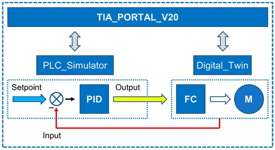
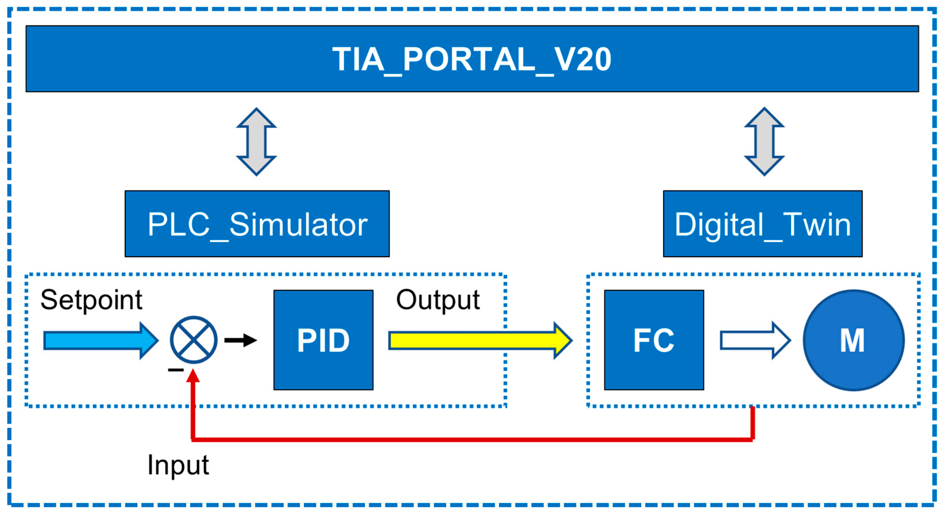
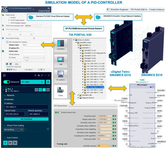
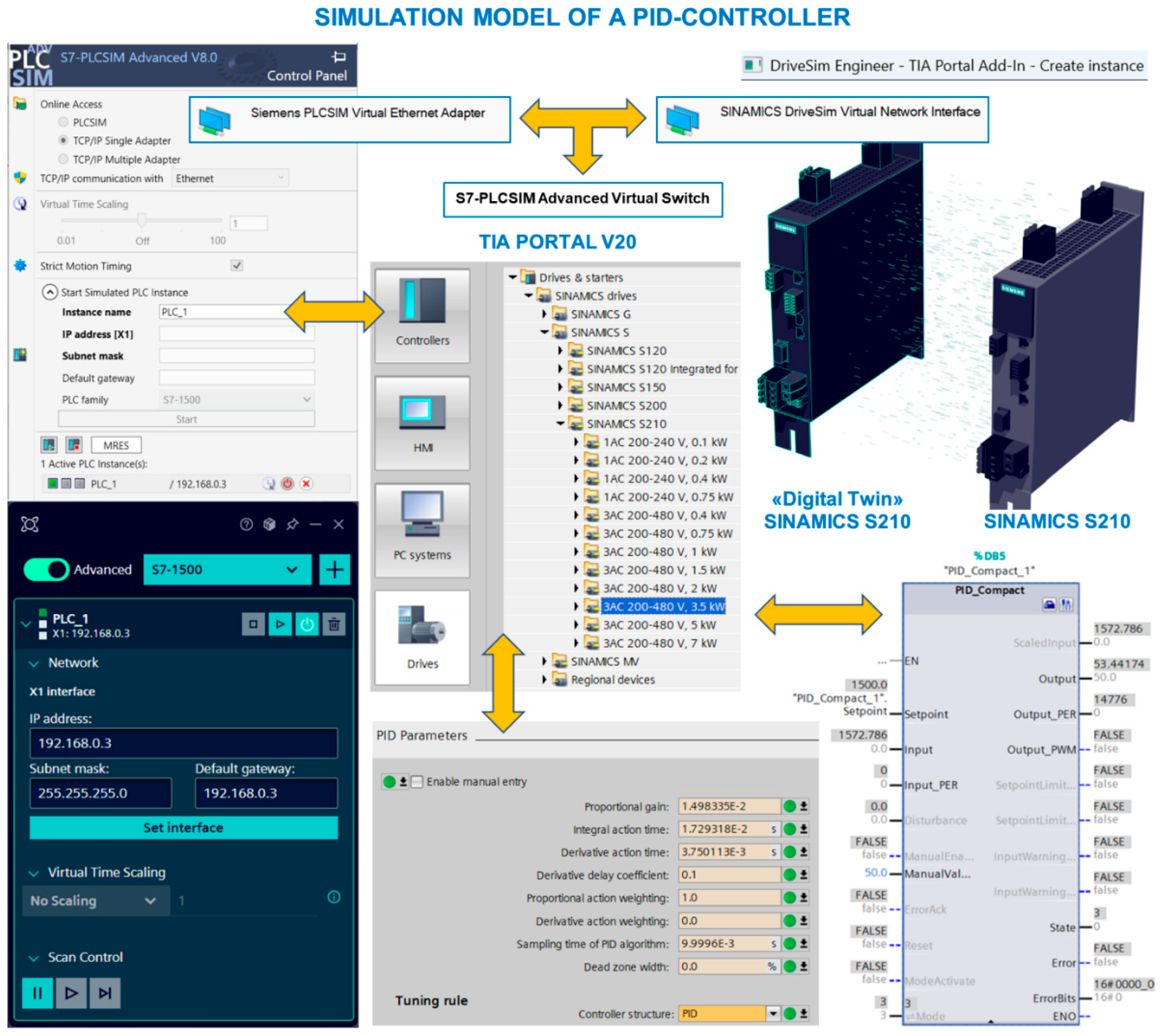
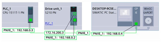
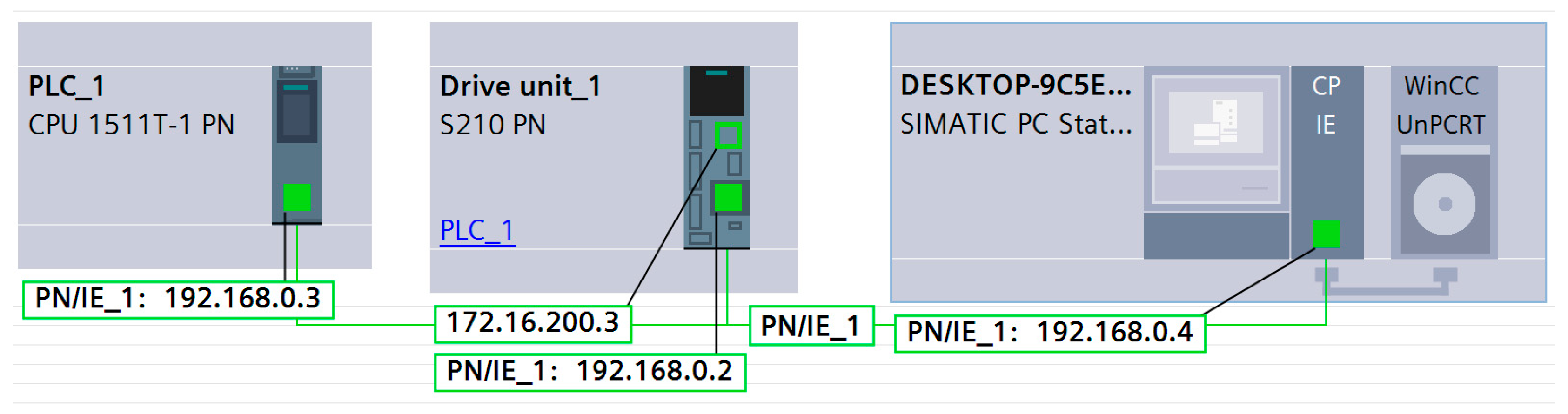
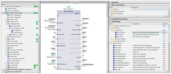
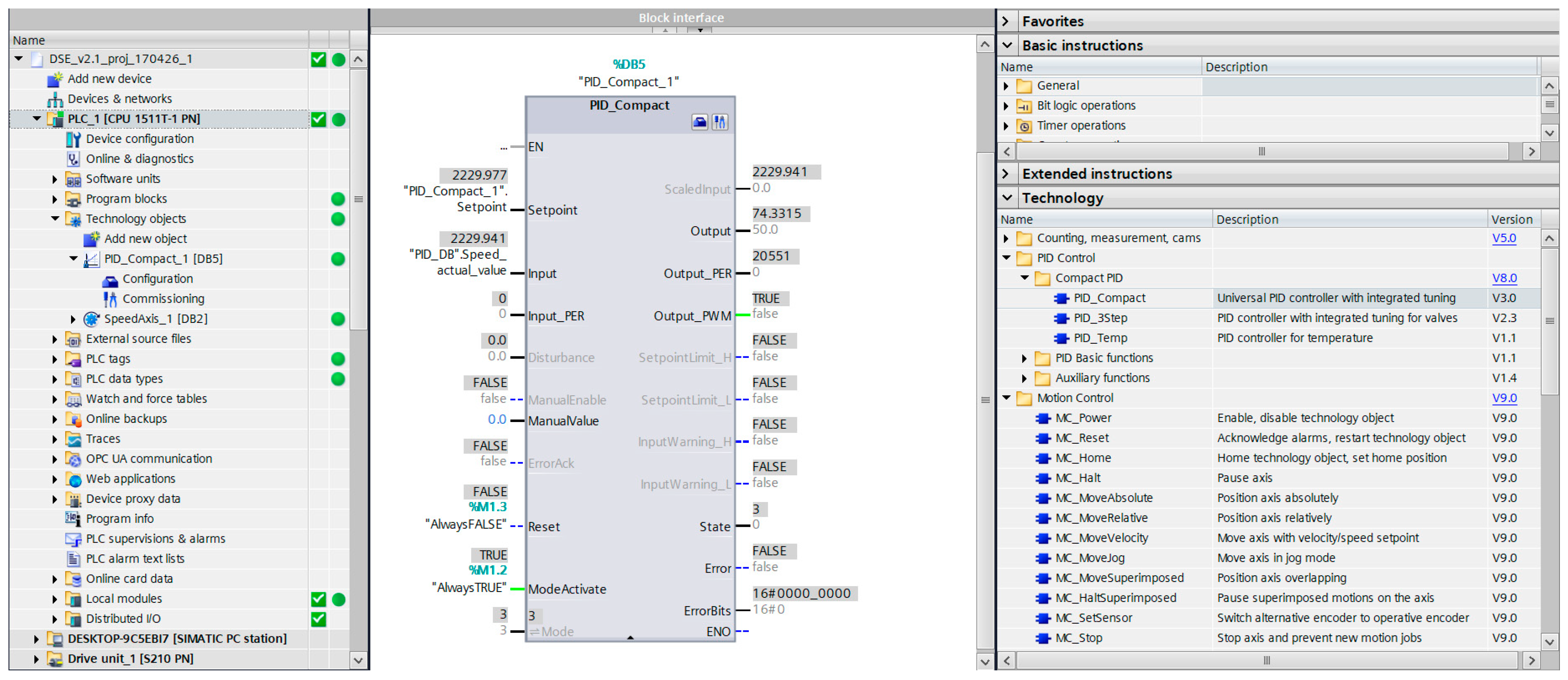
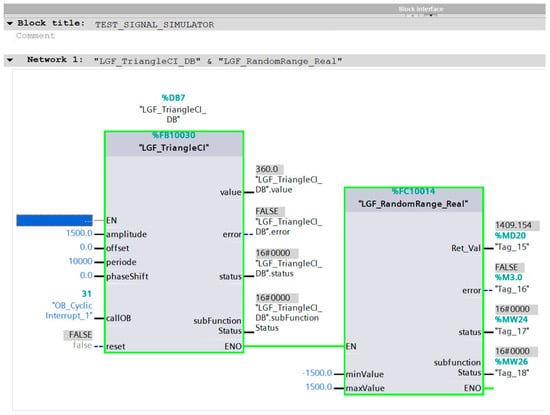
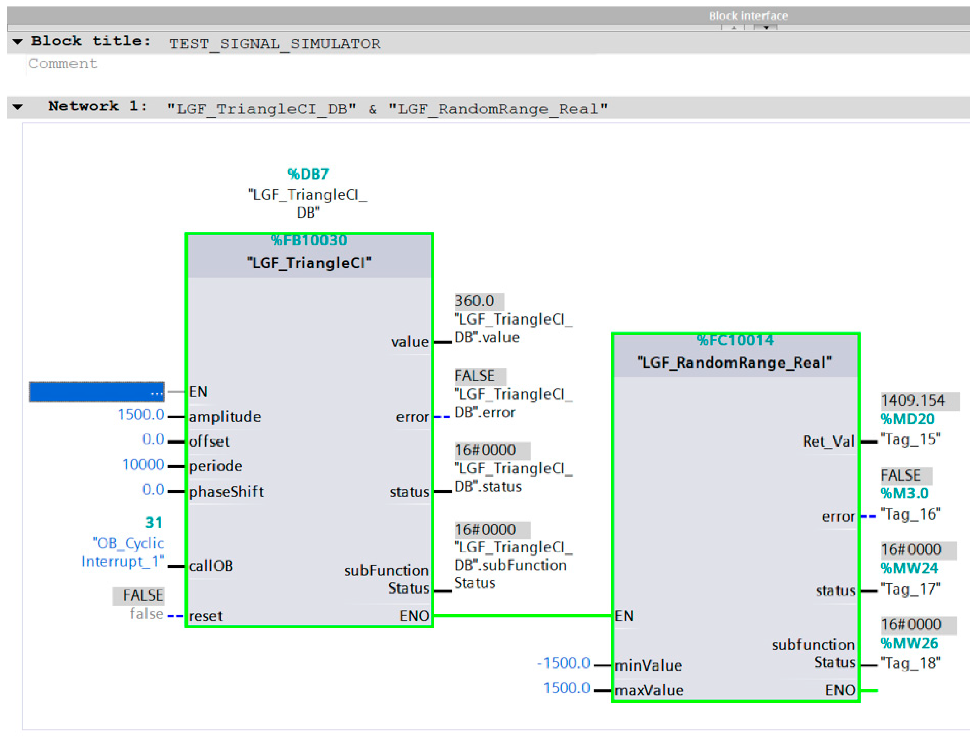
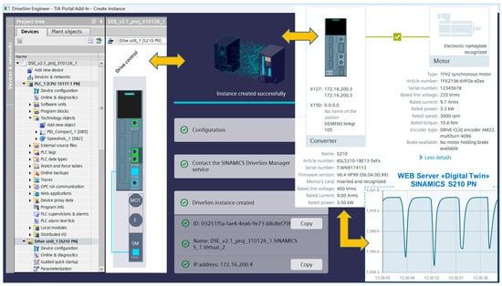
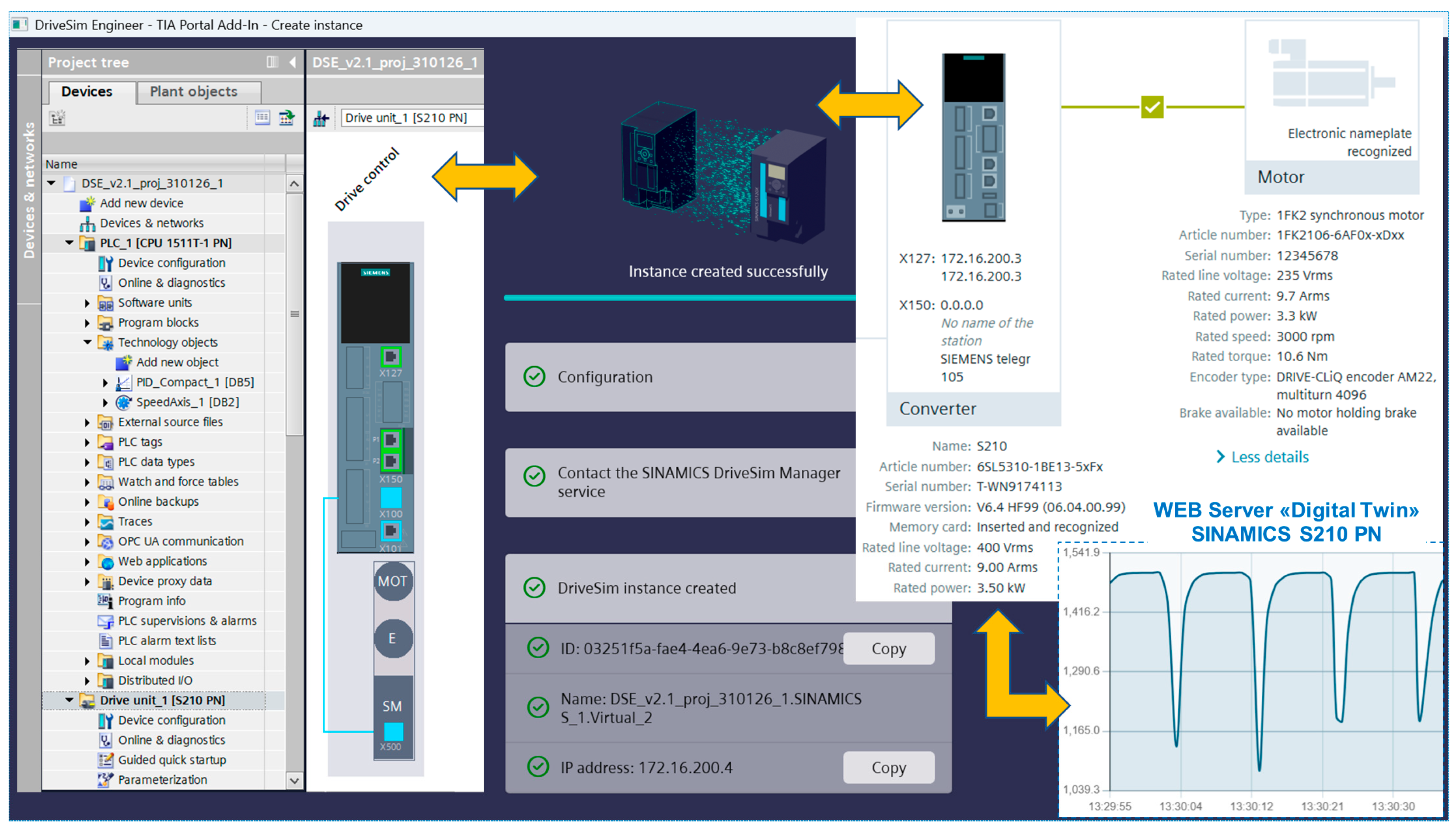
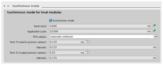
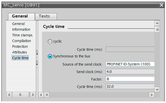
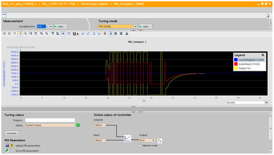
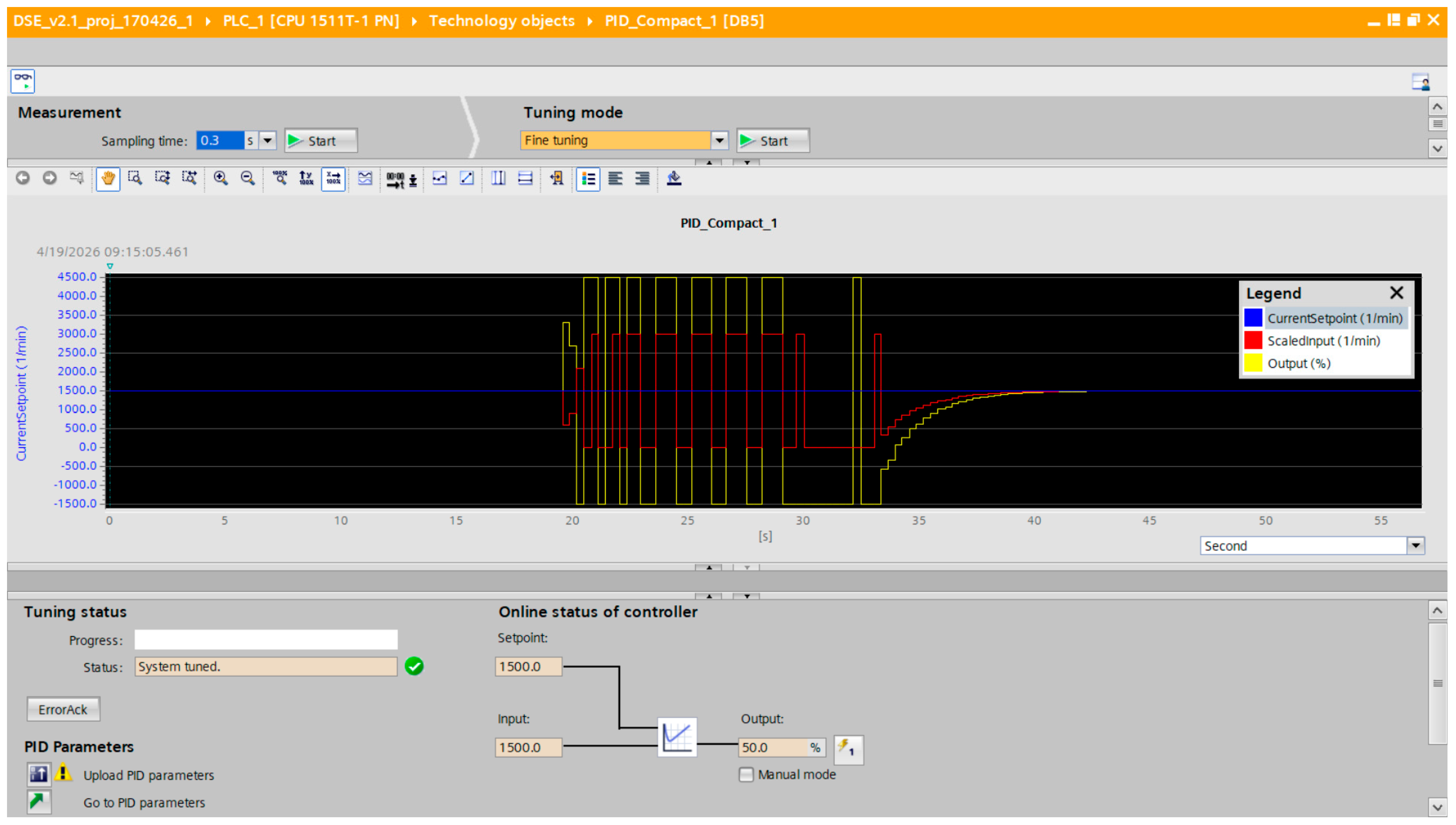


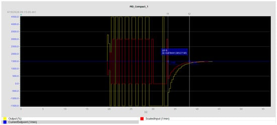
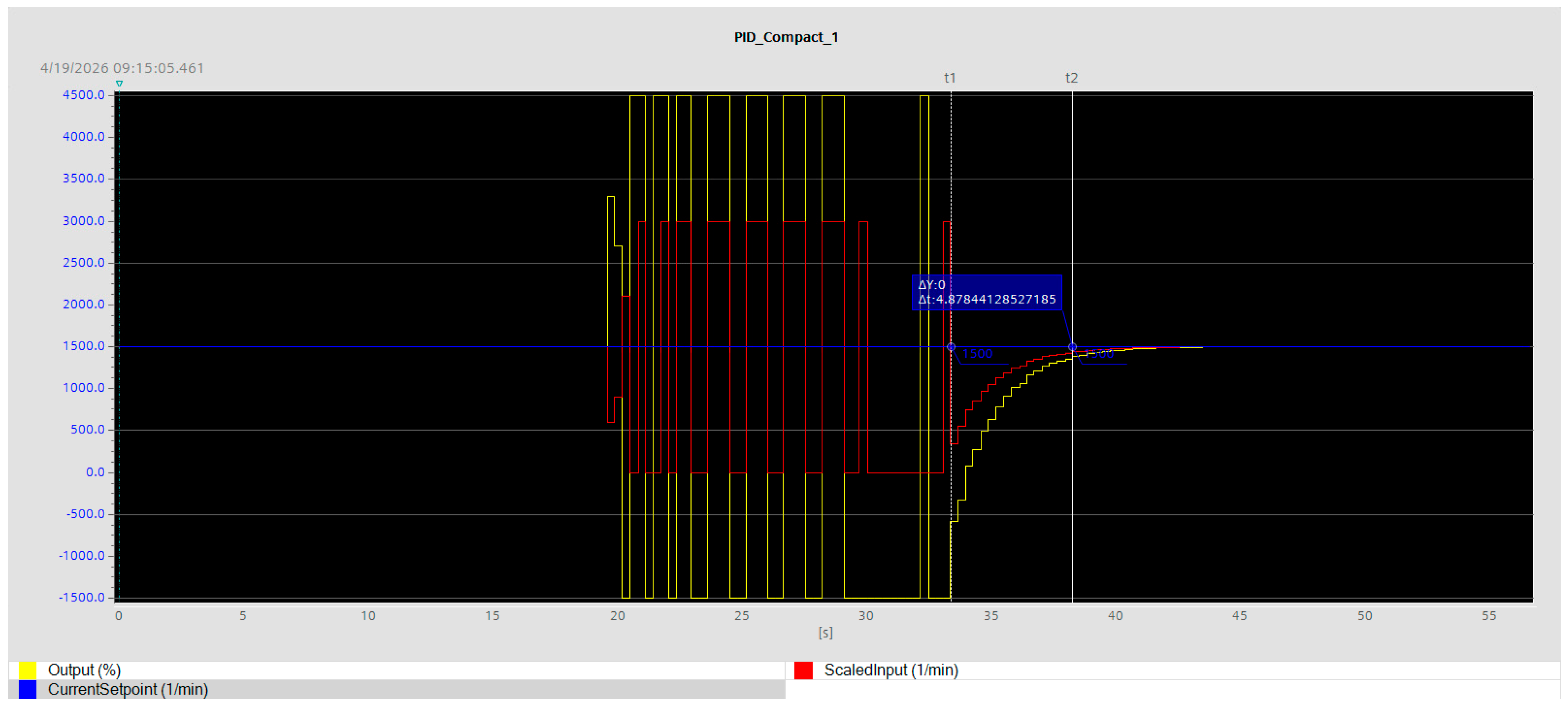
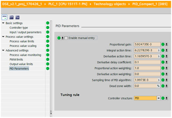
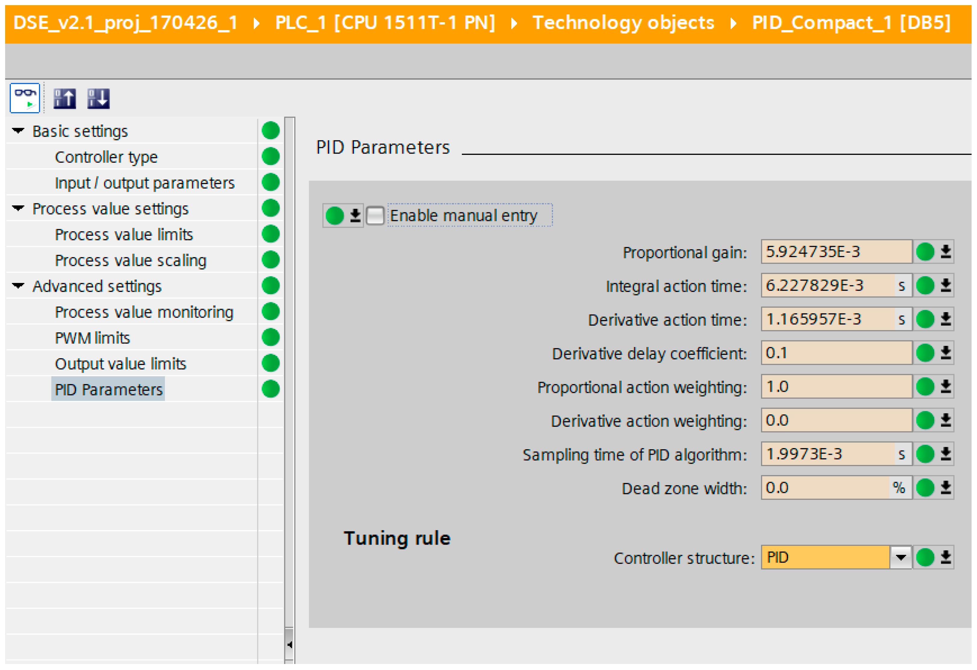
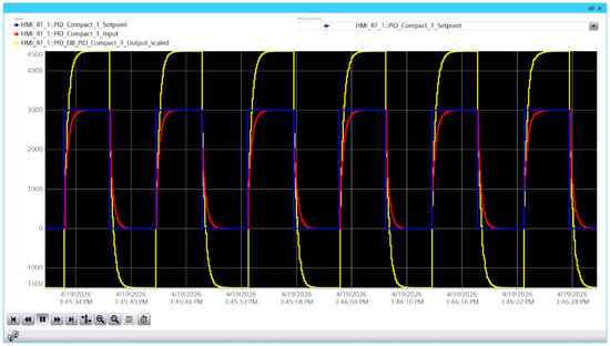
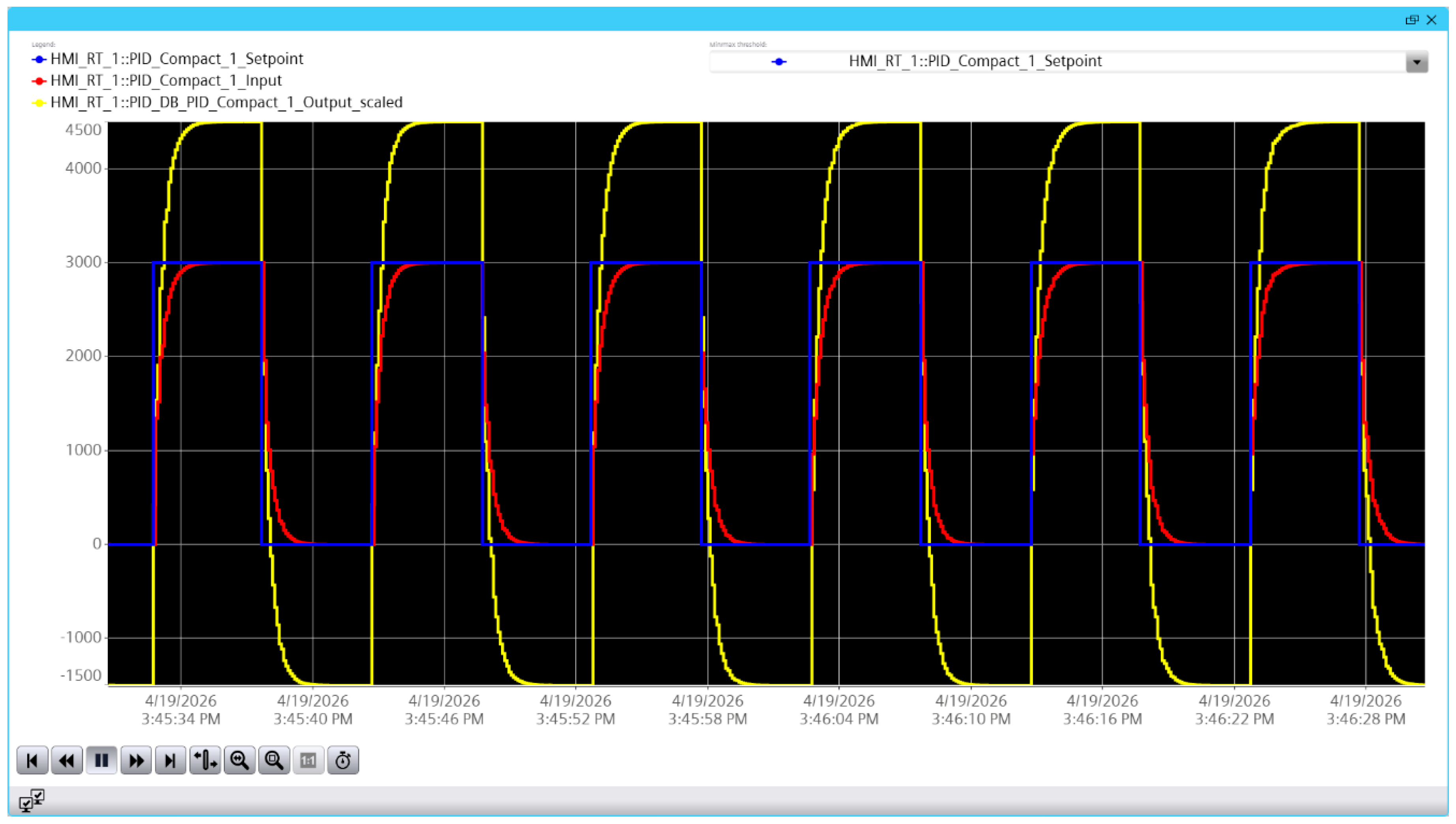
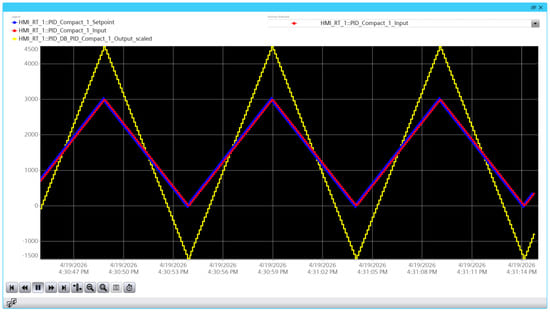
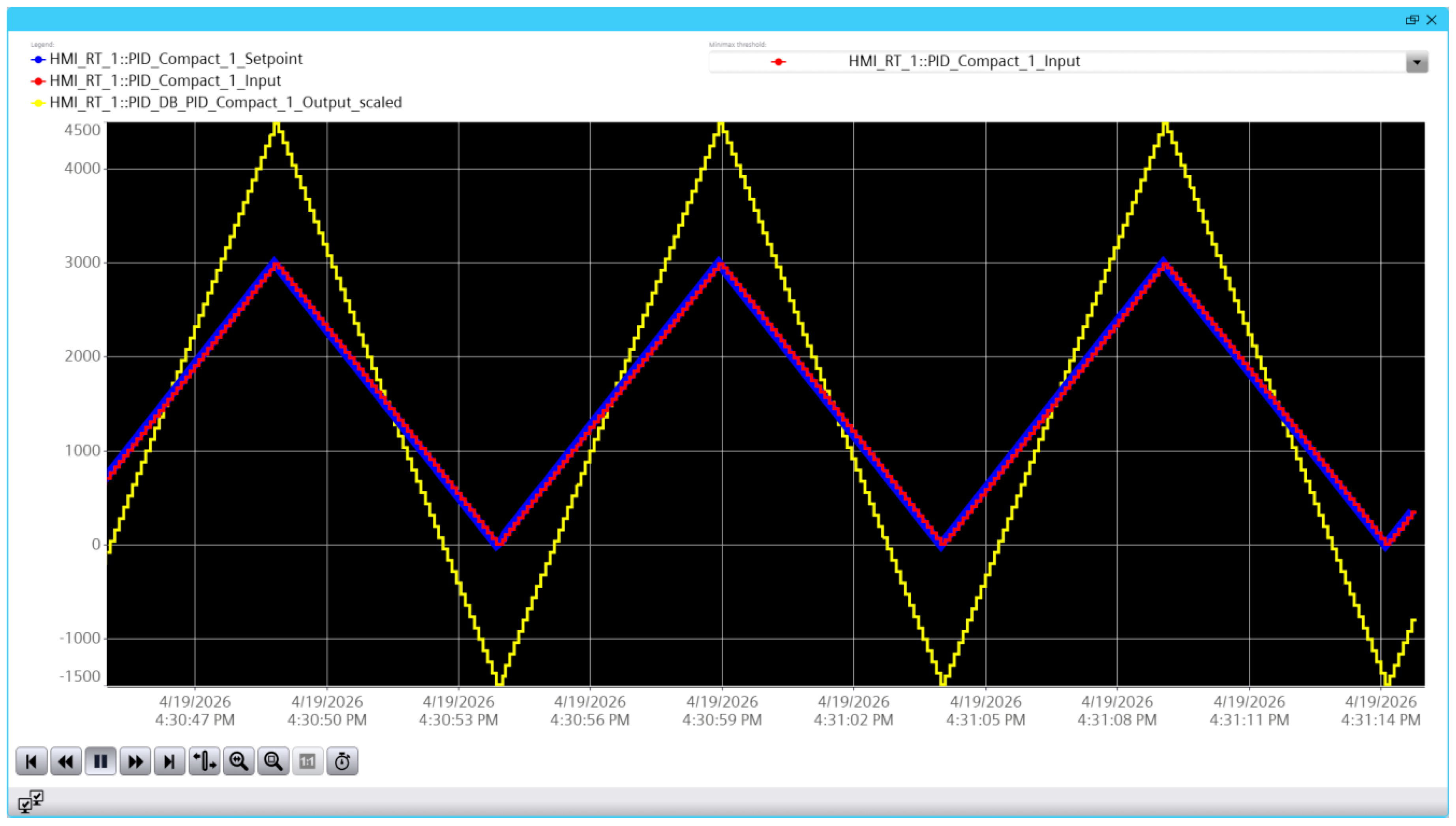
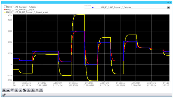
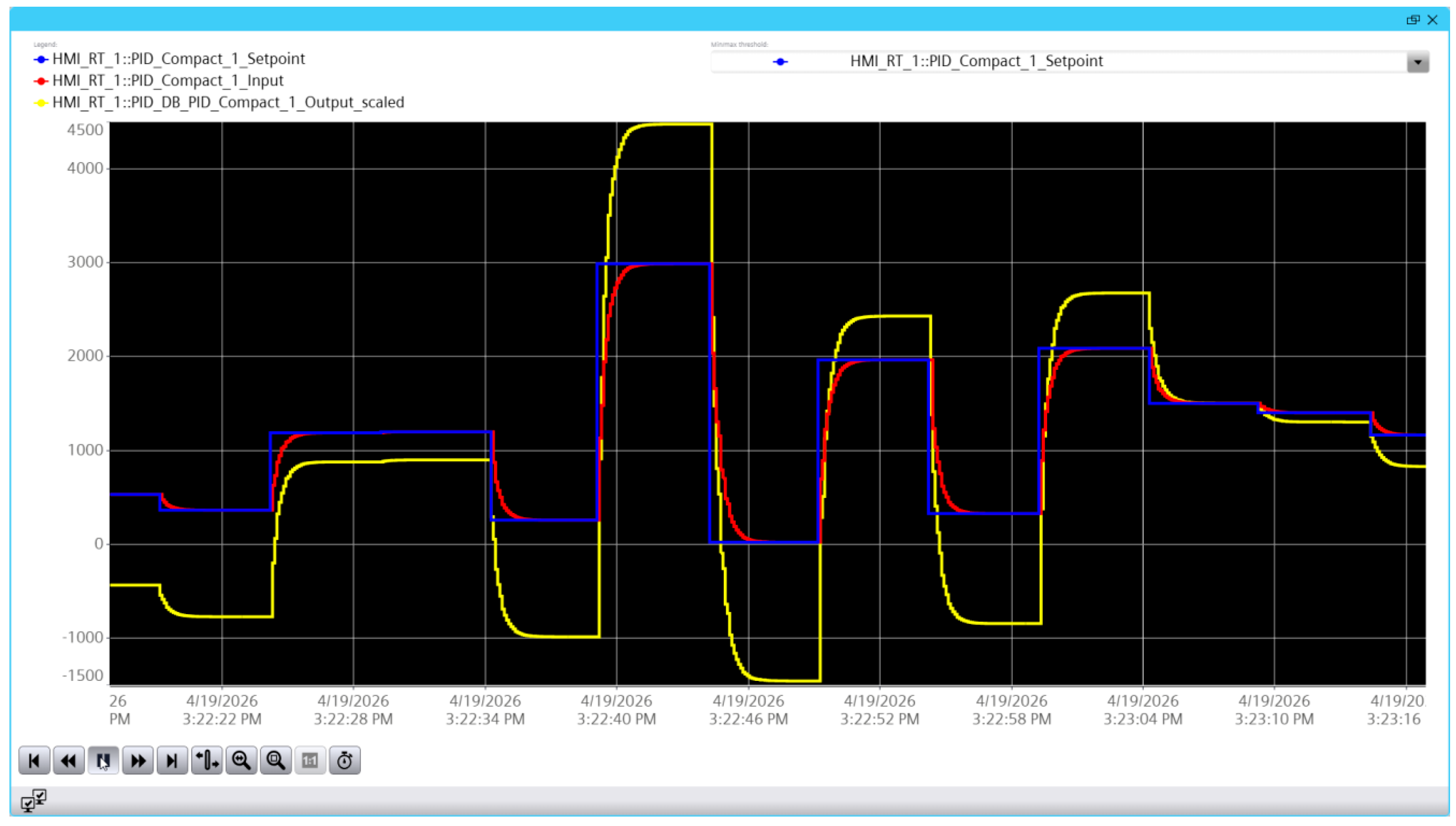

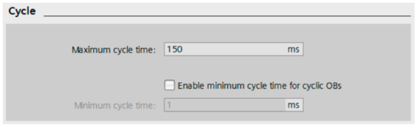

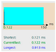

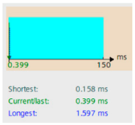
Disclaimer/Publisher’s Note: The statements, opinions and data contained in all publications are solely those of the individual author(s) and contributor(s) and not of MDPI and/or the editor(s). MDPI and/or the editor(s) disclaim responsibility for any injury to people or property resulting from any ideas, methods, instructions or products referred to in the content. |
© 2026 by the authors. Licensee MDPI, Basel, Switzerland. This article is an open access article distributed under the terms and conditions of the Creative Commons Attribution (CC BY) license.