


Abstract
In a globalized world where data play a critical role in system operation, process automation, and decision-making, the development of real-time control systems is essential, as it enables operators and supervisors to monitor the current status of a process based on its physical variables. Consequently, a wide range of software and hardware platforms is currently available for implementing real-time control systems, including Arduino, ESP32, and PIC microcontrollers. However, these platforms lack sufficiently robust hardware features for closed-loop control applications, as they were primarily designed for general-purpose use. To address the limitations of conventional embedded systems, this paper presents a novel approach for the implementation of digital controllers using Texas Instruments embedded systems applied to experimental plants designed with different control strategies. The proposed contribution focuses on the development of an experimental framework that integrates multi-platform programming, automatic code generation, and the use of dedicated real-time control modules, such as the Control Law Accelerator available in the LAUNCHXL-F28379D LaunchPad embedded system. The results highlight the capability of Texas Instruments microcontrollers to execute real-time control loops applied to different physical systems and operating under various control parameters. In conclusion, the findings demonstrate that Texas Instruments embedded systems equipped with advanced microcontroller architectures represent a promising alternative not only for scalable control applications but also for industrial-level control system development.
1. Introduction
Control engineering, like other areas of knowledge, has been constantly evolving in recent decades thanks to advances in technology at both the software and hardware levels. The most significant changes have occurred with the emergence of the industrial revolution and during the First and Second World Wars, events that demonstrated the need to implement robust control systems with much more rigorous and mathematically correct procedures [1]. In its early stages and with the development of the industrial revolution in Europe, there were controllers that could only be adjusted manually, which led J. C. Maxwell in 1868 to make a significant contribution to the development of control systems by linearizing the differential equations of motion to obtain a characteristic equation of a physical system through which stability parameters could be analyzed [1]. However, it was only between 1892 and 1898 that the first work on control based on system stability was performed and other important concepts in control such as the transfer function were developed [2,3].
The study and evolution of control systems have been marked by different stages: primitive control between 1868 and 1900, classical control in the period between 1900 and 1960, and modern control from 1961 to the present [1]. The first stage consisted of the initial development of control theory based on the solution of differential equations that described the stability of the systems under study. The second stage was based on the study of techniques in the frequency domain and the complex plane, applicable mainly to simple linear systems. Finally, modern control is based on analysis and design theory in the time domain, making use of state variables applied even to multiple-input multiple-output (MIMO) systems. The evolution in control systems has also changed the way they are implemented in practice, since previously control loops were implemented in analog form using mainly discrete elements such as resistors, capacitors, inductors, transistors, and operational amplifiers. These systems had precision problems because the elements used for their implementation were affected over time and by temperature changes, generated as a consequence of the heat they dissipate [4].
The limitations inherent to analog controllers can be addressed through digital control systems, which leverage digital signal processing to mitigate system variability by manipulating parameters that may affect performance and accuracy. Furthermore, in digital control systems, precision is also contingent upon the arithmetic type and word length employed in their implementation, as phenomena such as quantization noise and accumulator overflow must be considered. Although digital systems can enhance precision in control elements, it is equally important to account for factors related to system response time, instruction execution speed, and power consumption, given the requirement of certain control systems to perform continuous real-time decision-making [4,5]. In this regard, ref. [6] demonstrates that conventional Model Predictive Control (MPC) algorithms fail when sampling periods are exceedingly short, as computational time exceeds the available sampling interval, thereby driving the development of computationally efficient versions capable of executing within microseconds on ARM-based architectures. Another factor constraining the processing capability of digital controllers is the limited memory available in certain microcontrollers, necessitating optimization strategies to improve execution speed [7]. An alternative approach to alleviate the challenges is proposed in [8], which addresses the computational burden of electric machine control systems through interrupt-driven software architectures and task prioritization on dual-core microcontrollers, enabling simultaneous execution and emulation of control strategies. These considerations mandate the utilization of embedded electronics in digital controller implementations, where frameworks such as that proposed in [9] facilitate rapid and reliable embedded software development through Hardware-in-the-Loop (HIL) simulations.
Control systems have been essential for technological, academic, and industrial advancement, as they allow processes involving physical variables to operate within optimal values and parameters that lead to satisfying the growing demand for products with more detailed characteristics and more efficient operation. Therefore, different sectors of industry and the global economy are opting for compact and low-cost systems for the development of real-time control strategies. These systems have gained relevance due to the wide variety of physical and information processing characteristics with which they are equipped, and although some, such as Arduino, have been developed for general-purpose applications, currently there are others, such as embedded systems based on Texas Instruments (TI) C2000 microcontrollers, which have been developed primarily for the development of real-time control systems. C2000 microcontrollers emerged primarily as an alternative for large-scale industrial control through the inclusion of advanced hardware capabilities and optimization in the execution of instructions for control loops. However, currently this type of device has expanded to other types of environments such as academic settings in technology and engineering programs [10].
Finally, the structure of this paper is organized as follows: Section 2 presents a review of the literature on embedded systems used in real-time digital control applications. Section 3 presents the methodology used, which is divided into two main parts: Section 3.1 describes the test plants used and their continuous-time mathematical models, and Section 3.2 shows the experimental development of the implementations carried out and includes the discretization processes of the plant models used and the development of the digital controllers. Section 4 presents the results obtained in the test plants, comparing the results obtained in simulation and real-time operation. Finally, Section 5 presents the main conclusions obtained and future projections.
2. Literature Review
According to Section 1, in different research studies conducted on digital controllers, various embedded systems have been used for signal processing in the control law, which have been programmed through multiple platforms using different programming languages, among which the C/C++ language stands out. All these elements have been integrated for the development of real-time controllers through classical and advanced control techniques.
In Refs. [11,12], fuzzy logic controllers were developed for pressure control in tanks. In the first, the Takagi-Sugeno model was used, and in the second, the Mamdani model. Atmel ATmega 8 and AT89C51RC microcontrollers programmed in C language were used as processing systems. Ref. [13] presents the implementation of a Linear Quadratic Regulator (LQR) for position control of a pendulum through the Rapid Control Prototyping (RCP) technique using Simulink/MATLAB. For the development of the real-time control strategy, an ARM AT91SAM9263 processor from Atmel Company and a TI F2812DSP were used. Other applications of embedded systems are oriented toward the development of Internet of Things (IoT) applications such as the one carried out in Ref. [14], where a Peripheral Interface Controller (PIC) 24FJ48GJ002 microcontroller was used for the design and implementation of a universal board for real-time measurement and control applications. In Ref. [15], the design and implementation of an integrated real-time control system for a four-rotor helicopter were performed. The control techniques used were oriented toward the use of nonlinear and linear control strategies such as the Proportional—Integral—Derivative (PID) controller. For the processing of control signals, the Texas Instruments TMS320F2812 embedded system was used, which was programmed in C language through Code Composer Studio (CCS). Additionally, Ref. [16] presents the development of a low-cost system for control engineering education processes through Rapid Control Prototyping (RCP), using low-cost hardware, such as Arduino Uno through an ATmega328P microcontroller and Simulink/MATLAB for controller design, simulation and hardware implementation. In Ref. [17], a wind turbine simulator (WTS) that uses a 5 VDC direct current motor and a direct current converter to emulate the real characteristics of wind turbines was proposed. A C2000 Delfino TMS320F28335 microcontroller was used to calculate torque as a function of wind turbine characteristics and control the direct current drive. Programming for real-time monitoring and parameter adjustment was performed through Code Composer Studio (CCS). Ref. [18] proposes a reference framework for implementing digital control strategies using Texas Instruments C2000 microcontrollers through the Energia IDE. In the experimental framework, Texas Instruments LAUNCHXL-F28379D embedded systems and C language programming were used for the implementation of different control techniques such as PID and RST. Other works, such as Ref. [19], include developments through the Xilinx Zynq-7000 FPGA that includes a dual-core ARM Cortex-A9 processor for the implementation of Lipschitz interpolation (LI) algorithms using parallelism techniques for simultaneous data processing. In Ref. [20], a methodology for control design and low-cost Hardware-in-the-Loop (HIL) simulation of a multivariable interconnected smart grid is presented. A discrete-time Linear Quadratic Regulator (LQR) controller for the real-time multivariable system using two microcontrollers is proposed: Texas Instruments C2000 Delfino and the Arduino DUE embedded system. Another work where the LAUNCHXL-F28379D development board was used is presented in Ref. [21], where the integration of Texas Instruments C2000 microcontrollers with MATLAB and Simulink Embedded Coder for real-time control applications is detailed. In this work, the BOOSTXL-BUCKCONV BoosterPack DC-DC converter was used for the development of a discrete PI controller. In Ref. [22], a digital control system for biofermentation was designed using an ARM9 S3C2410A microprocessor and embedded Linux. It employs a fuzzy PID controller designed in MATLAB to regulate temperature. Additional research efforts have been directed toward the development of techniques and methodologies that diverge from conventional approaches. For instance, in Ref. [23], a Model Predictive Control (MPC) strategy was implemented using C2000 microcontrollers for a four-level multilevel converter supplying an Interior Permanent Magnet Synchronous Motor (IPMSM) drive, incorporating DC bus voltage imbalance compensation, which was validated through Hardware-in-the-Loop (HIL) testing. In Ref. [24], the concept of Experimentable Digital Twins (EDTs) was introduced to integrate simulation techniques with Internet of Things (IoT) technologies, enabling the creation of interconnected virtual networks for system simulation within the Industry 4.0 paradigm. In Ref. [25], a C++ library was developed for neural network training directly on microcontrollers, enabling on-device adaptation for real-time applications. Finally, in Ref. [26], an MPC-based control system was implemented for a hybrid steam boiler system with solar preheating, employing HIL simulation on C2000 microcontrollers to validate the controller performance in real-time through system state estimation.
The works consulted in the literature (Refs. [11,12,13,14,15,16,17,18,19,20,21,22,23,24,25,26]) and others that were reviewed but were not taken into account due to their similarities because they consisted of similar studies are oriented toward the implementation of real-time digital control systems, but very few include the use of microcontrollers or embedded systems for specific use in digital applications such as Texas Instruments embedded systems. This highlights the research conducted and its contribution to the literature, where TI embedded systems and microcontrollers that integrate specific modules for real-time control such as the Control Law Accelerator (CLA) into a single application are used.
3. Methodology
The methodology used in the development of this research was based on an experimental framework for the implementation of digital control strategies using Texas Instruments C2000 microcontrollers (Dallas, TX, USA). The processing of control signals was facilitated by the LAUNCHXL-F28379D embedded system, which was equipped with a dual-core C2000 Delfino TMS320F28379D microcontroller. The programming of these microcontrollers for the test plants used was carried out through three different platforms: Simulink/MATLAB R2025b, Code Composer Studio (CCS) 12.8.1, and Energia IDE 0101E0017, using C/C++ programming languages.
Additionally, this section is structured in two parts: The first focuses on the characterization of the test plants and the development of their continuous-time mathematical models. The second part shows the discretization of the test plants used and the experimental design of the proposed digital controllers.
3.1. Test Plants
The test plants were chosen according to methodological criteria rather than complexity. The research focused on cross-platform development and automatic code generation using Texas Instruments C2000 microcontrollers, rather than demonstrating advanced control of complex systems. First- and second-order systems are widely adopted as reference plants in digital control literature, enabling comparisons with prior works, and although mathematically simple, the selected plants represent real industrial processes. In our case, the flying cutting plant is a scale prototype of an industrial continuous cutting system that is available in the Instrumentation and Control Laboratory at the Universidad del Quindío. Level tanks are prevalent in chemical and water treatment industries, and both systems enable the academic study of industrial processes, their characteristics, variations, and limitations.
3.1.1. Simulation for Second-Order System
The first experimental prototype consists of a second-order underdamped system implemented using operational amplifiers. The system dynamics can be represented in state space form according to (1).
where the system matrices are defined as follows:
The open-loop system exhibits underdamped behavior with a settling time of approximately 60 s and an overshoot of 108.33%, which makes it suitable for evaluating the performance of different control strategies.
3.1.2. Simulation for Flying Cutting Prototype
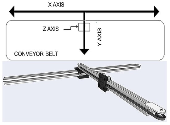
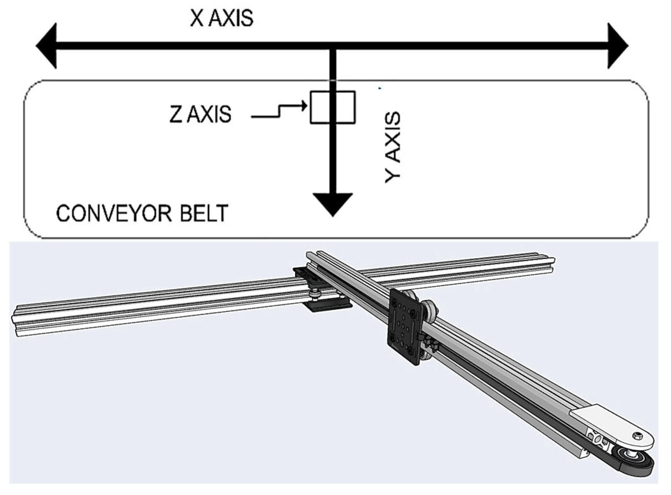
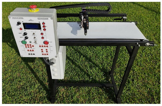
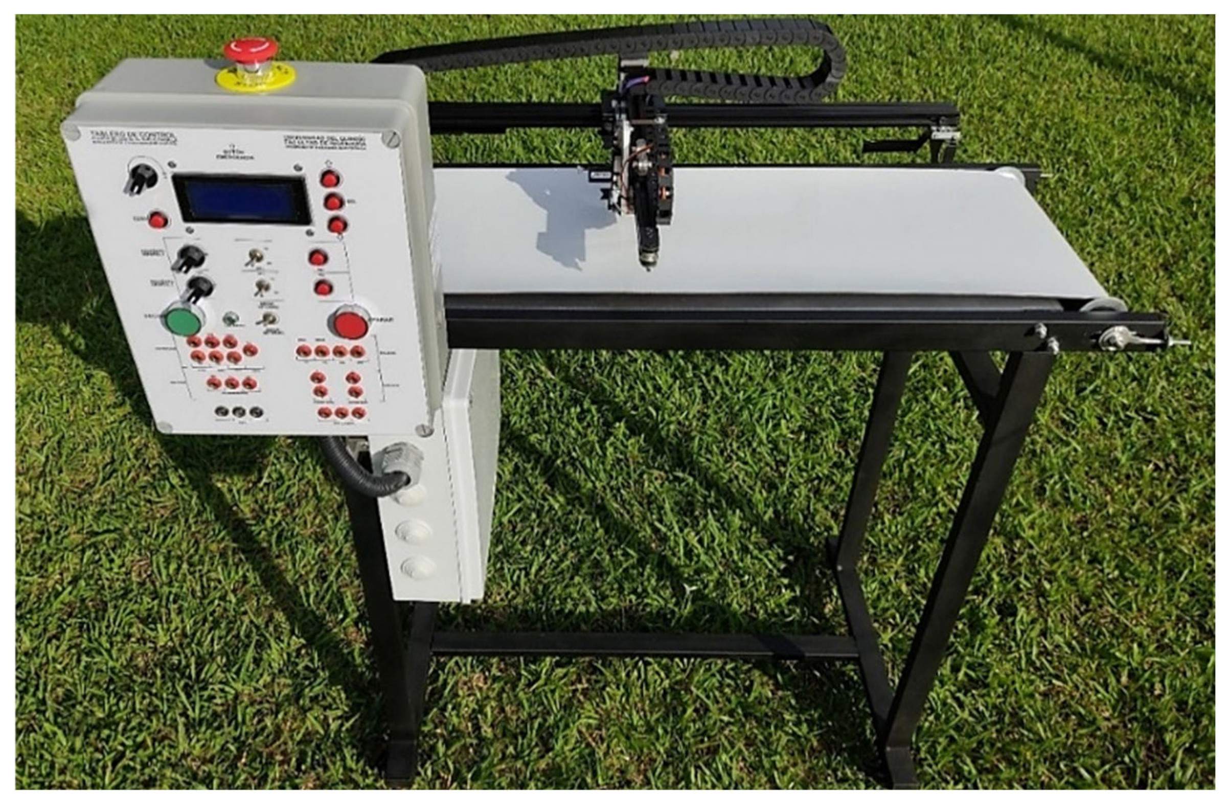
Flying cutting plants are machines that cut moving parts through a mechanical synchronization process between the blade and the moving material. At the industrial level, there are different types of flying cutting machines, which are defined or classified by manufacturers such as RISHBIN. The latter’s catalog includes machines for cutting metal plates classified as rotary, swivel lever, and pendulum machines [27]. The cutting mechanism is composed of an X and Y coordinate system that generates the movement of the conveyor belt and a servomotor on the Z axis that executes the cutting action. The prototype of the flying cutting plant is illustrated in Figure 1.
Figure 1.
Prototype of flying cutting plant.
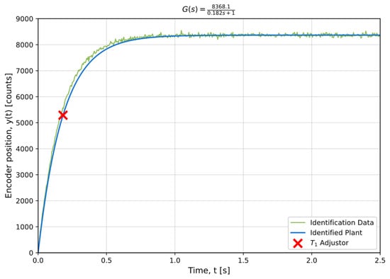
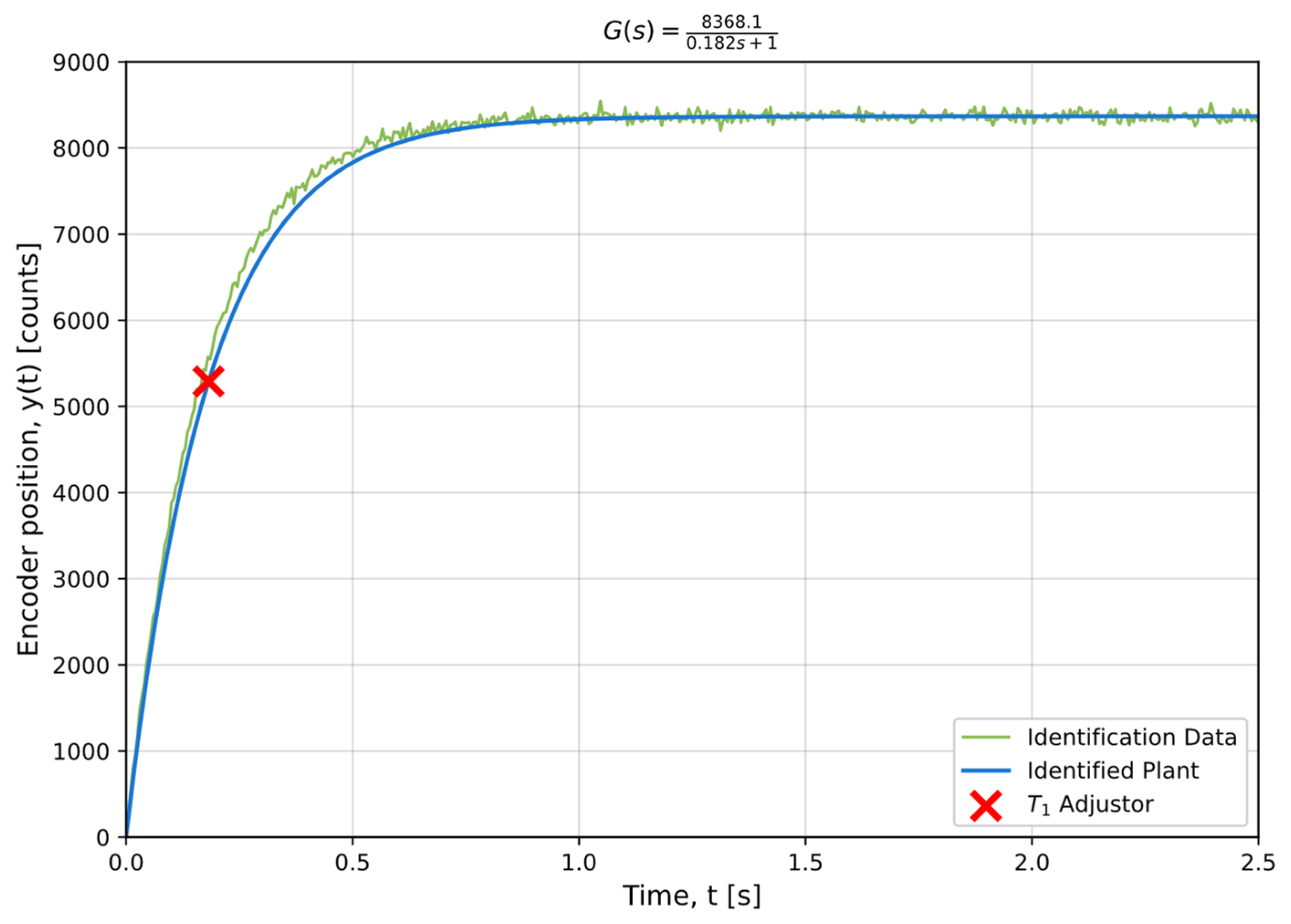
To obtain a mathematical model for the flying cutting plant prototype, an identification process was carried out using the MATLAB System Identification Toolbox based on the input signal and the system response. The summary of the identification process is shown in Figure 2, and the mathematical model obtained is presented in (3).
Figure 2.
Identification response for flying cutting plant.
3.1.3. Simulation for Level Tank
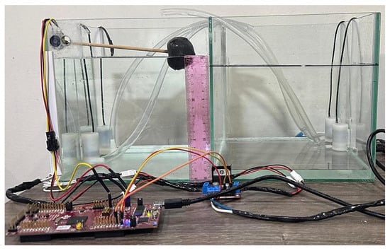
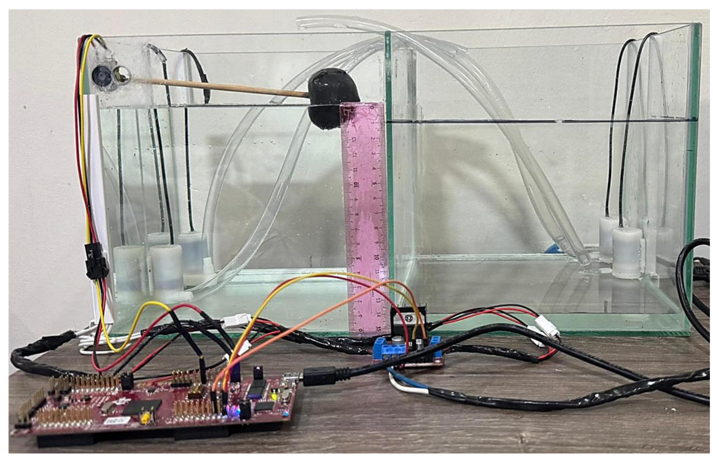
The level tank used in this study was a 16 L glass tank equipped with two motor pumps and a potentiometer to measure the internal level. The motor pumps employed in this system are actuated by pulse-width modulation (PWM) signals, and the system as a whole is powered by a 5 VDC power source. The level plant used in the experimental framework of this research is illustrated in Figure 3.
Figure 3.
Front view of level plant used.
The mathematical model that describes the response of the level plant is shown in (4). This model was obtained using the same methodology as for the flying cutting plant, using an off-line identification process in MATLAB.
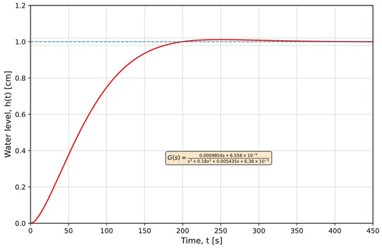
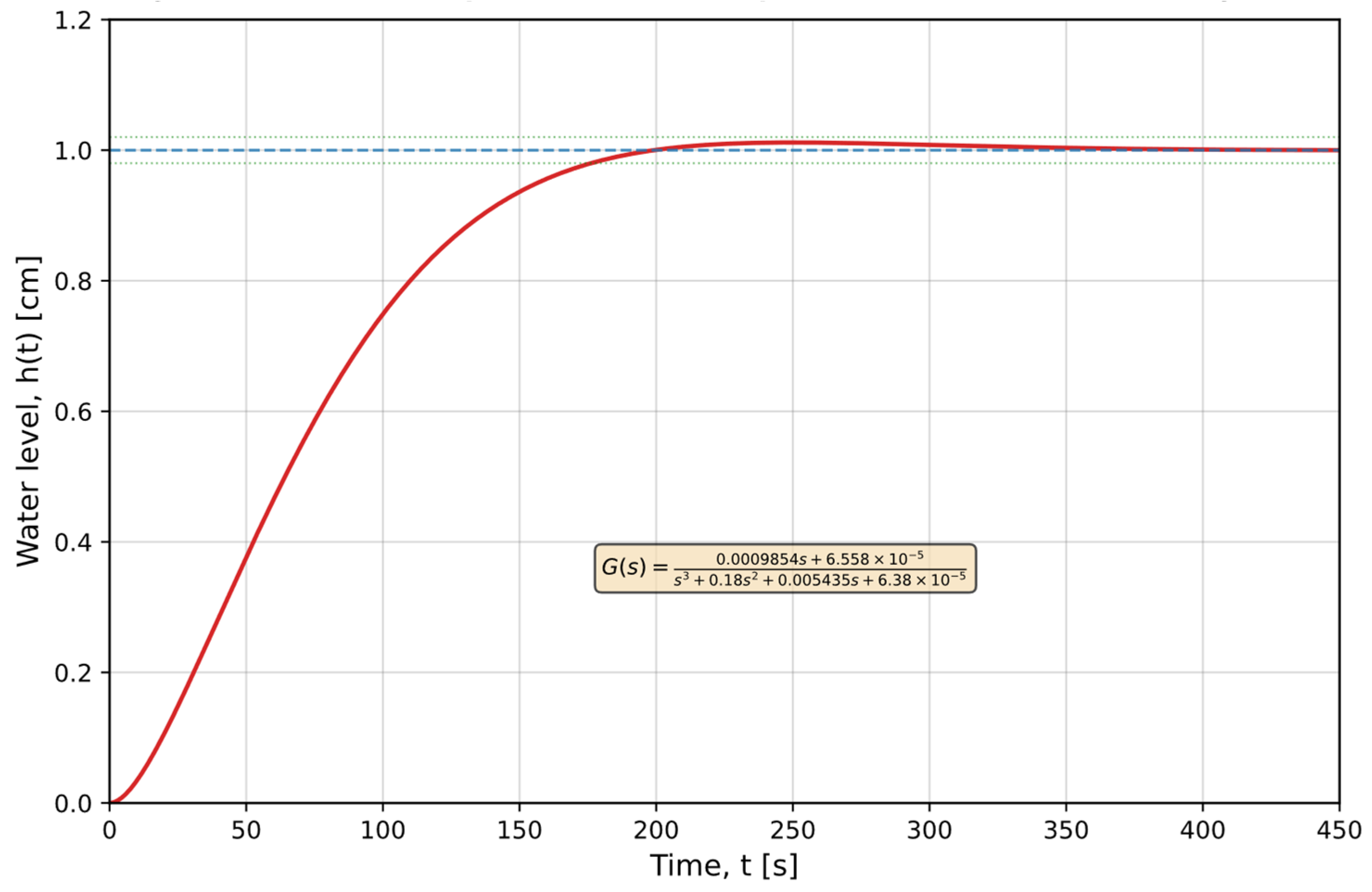
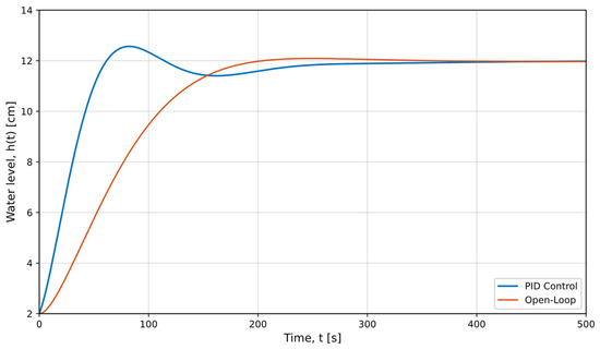
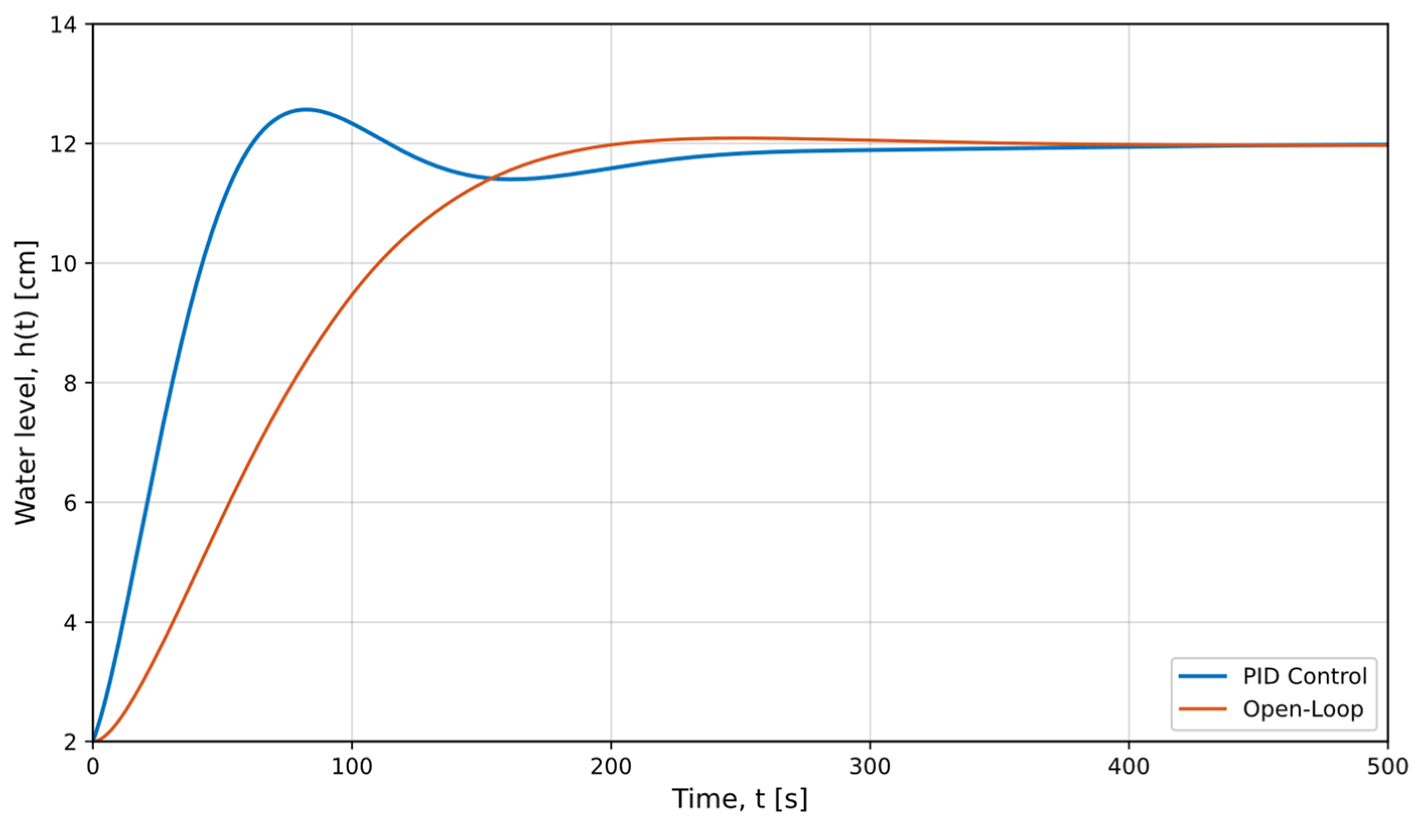
After obtaining the mathematical model of the level plant, its response was obtained. The dynamics of the level plant in the transient response show characteristic behavior of this type of system, and it is observed that its response settles in approximately 176 s considering the 2% criterion as the error band for the final steady-state value. The transient response of the level plant is demonstrated in Figure 4.
Figure 4.
Transient response for level plant described mathematically in (4).
Finally, Table 1 presents a summary of the main hardware-level parameters for each of the test plants used, including important elements such as sensor resolution, actuator characteristics, signal conditioning, and data acquisition hardware.
Table 1.
Summary of hardware elements used in test plants.
3.2. Experimental Design
For the experimental design of the tests and validation of the digital controllers applied to the test plants described in the previous section, three PID controllers were proposed. In this research, they were designed using different tuning methodologies including Ziegler-Nichols method and direct tuning through RCP, using software tools like MATLAB PID Tuner, CCS, and Energia IDE 0101E0017 [28,29].
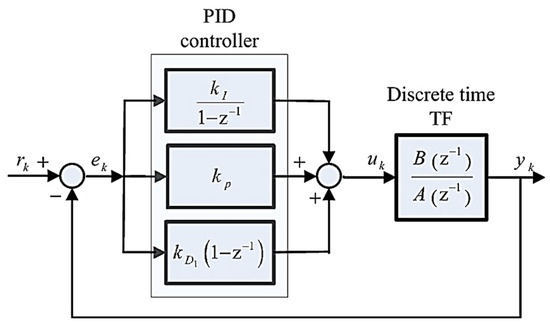
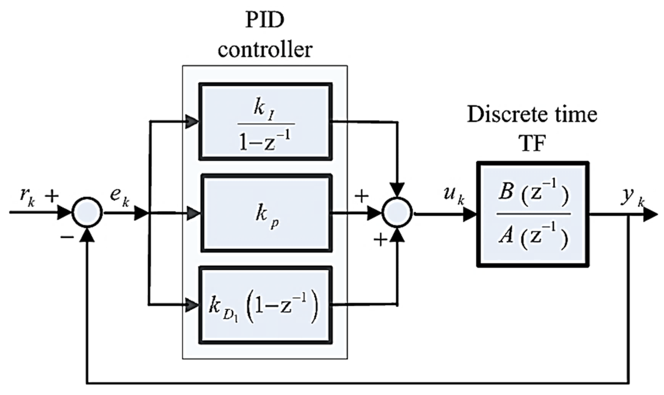
For the implementation of the digital PID controllers on the LAUNCHXL-F28379D development board, a parallel structure for the discrete PID controller as shown in Figure 5 was used, and the design specifications shown in Table 2 were employed. The following sections describe the design procedure for the controllers of each test plant [22].
Figure 5.
Discrete PID controller structure in parallel configuration.
Table 2.
Design specifications for the PID controllers in the test plants.
The design criteria established in Table 2 for the digital controllers were defined considering the inherent dynamic characteristics of each system. For the second-order plant, a settling time of less than 60 s was established based on the system time constant, a criterion that ensures the response reaches the desired values. For the remaining plants, a relative criterion was adopted, seeking a closed-loop settling time shorter than the open-loop response time, thereby ensuring that the designed controllers improve the natural dynamics of the systems without affecting the physical and dynamic characteristics of the plants. Regarding overshoot, values below 5% were established since, in practice, elevated overshoot in level temperature and similar systems indicate that the system exceeds the maximum allowable limits.
To choose the sampling time () in the test plants, concepts from digital control theory related to the sampling frequency and natural frequency of each plant were considered, with the aim of providing a faster response speed in the controlled systems subject to the dynamic characteristics of each plant. It is important to clarify that the sampling time is calculated based on estimates that allow it to be adjusted to lower values or, in some cases, to higher values. Decreasing sampling time generally helps improve system performance with more accurate information and better responses to disturbances. There are elements that must be considered for sampling time variation: computational load, signal quantization, and hardware limitations. This is why fixed sampling times were established for simulation and implementation in the research.
3.2.1. Controller Design for Second-Order System
The design of the PID controller for the second-order underdamped plant began with the discretization of its mathematical model, using a sampling time of s. The discrete model for the plant is shown in (5), and it was obtained using the c2d function in MATLAB and its structure, .
G(s) = continuous-time state space model and G(z) = discrete-time state space model. The control loop proposed for the PID control of the plant is shown in Figure 6.
Figure 6.
Proposed control loop for second-order plant.
Using the control loop defined in Figure 6, controller tuning was performed in the MATLAB PID Tuner. The design parameters shown in Table 2 were considered for this controller. After the tuning process, the control system output response presented in Figure 7 was obtained with constants , , and .
Figure 7.
Response of PID controller in second-order plant.
With the values of the constants , , and for the PID controller, the difference equation was obtained so that it could be implemented on the C2000 microcontroller of the LAUNCHXL-F28379D development board. Finally, the discrete transfer function for the PID controller is as follows:
Substituting the values of , , and into (6), we obtain the following:
Applying the inverse Z transform to , we obtain the difference equation for the PID controller as shown in (8).
Finally, (8) is the equation that will be used in Section 4 for the implementation of the digital PID controller. As mentioned earlier, the PID controller has different structures and tuning methods. For this research, (8) was obtained from the proposal in Ref. [30].
3.2.2. Controller Design for Flying Cutting Plant
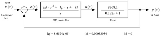
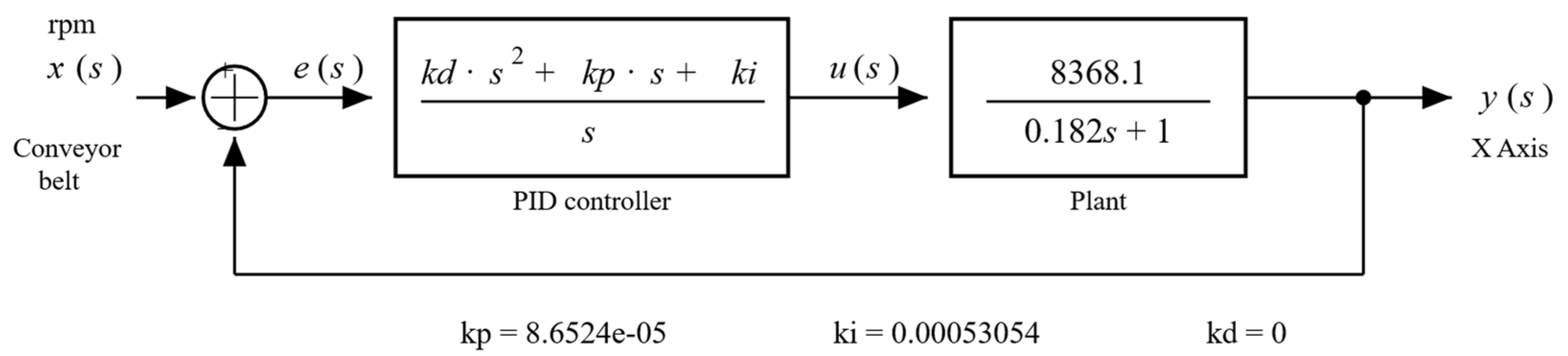
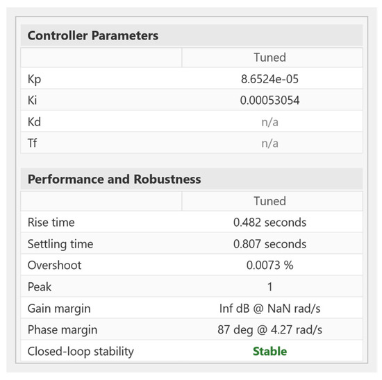
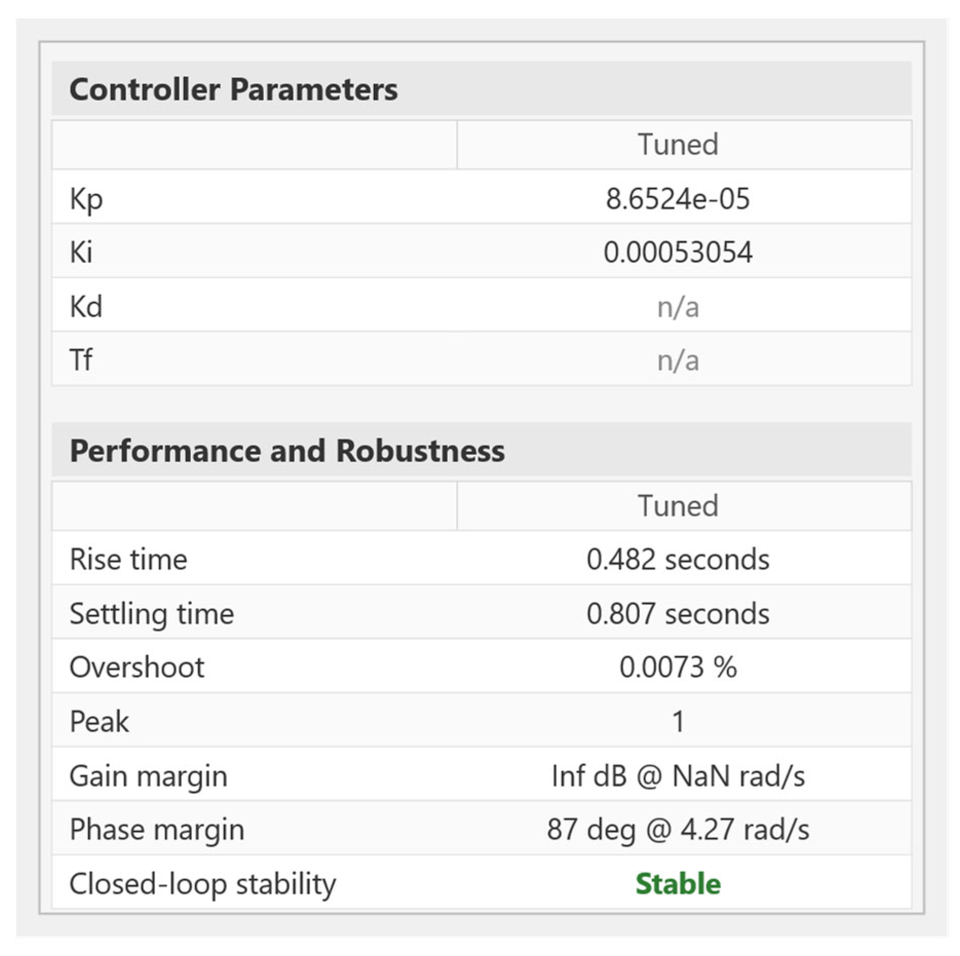
For the design of the flying cutting plant controller, the design parameters shown in Table 2 were considered. For this controller, a PI structure was chosen due to the characteristics of the plant, where it was not necessary to implement derivative action. The PI controller for the plant described in (3) was tuned using the MATLAB PID Tuner with the control loop shown in Figure 8, resulting in the and constant values shown in Figure 9.
Figure 8.
Proposed control loop for flying cutting plant.
Figure 9.
and constants obtained with MATLAB PID Tuner.
Figure 10 shows the simulation of the PI controller obtained with MATLAB PID Tuner. Figure 10a shows that the control system allows the plant to follow the reference, and Figure 10b indicates that the control effort signal is small and does not require excessive effort to bring the system to the reference.
Figure 10.
Normalized response for closed-loop PI controller and control effort in flying cutting plant. (a) Step plot: Reference tracking; (b) Step plot: Controller effort.
To implement the system described above in digital form, the sampling time () was calculated according to the behavior of the open-loop and closed-loop poles. To achieve this, the digital implementation performed in [28,29] was used as a reference to obtain the following difference equation:
It is important to remember that the flying cutting plant will have a PI controller, so the derivative action is equal to zero; therefore, (9) can be rewritten as follows:
3.2.3. Controller Design for Level Tank Plant
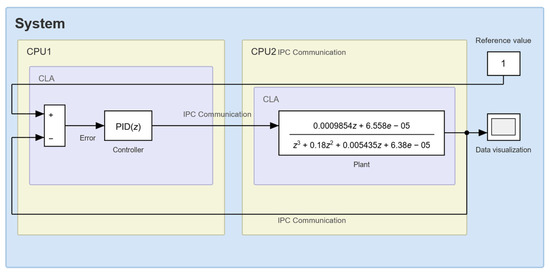
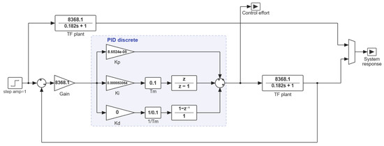
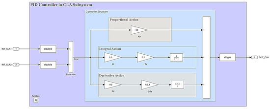
The PID controller for the level plant was designed so that the plant would respond quickly to reference changes. In addition, the behavior of the PID controller had to ensure a maximum overshoot of 2%, since any value above the reference could cause the plant level to overflow. Unlike previously designed controllers, the control loop for the level plant was designed using the two CPUs equipped in the C2000 microcontroller of the LAUNCHXL-F28379D LaunchPad (CPU1: PID controller and CPU2: level plant), and the PID controller was developed using the Control Law Accelerator (CLA) module. The block diagram of the PID controller for the level plant is shown in Figure 11.
Figure 11.
Proposed control loop for level plant.
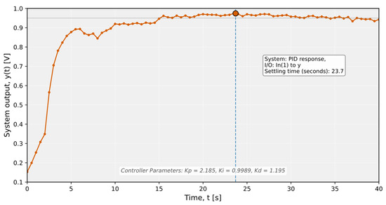
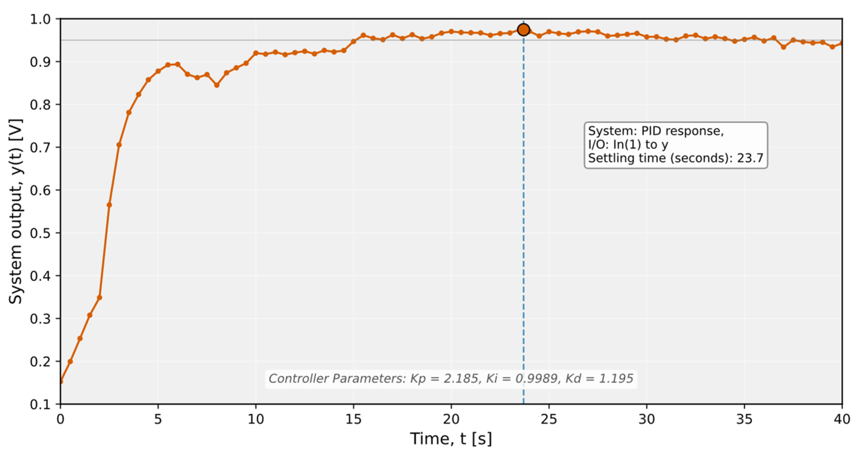
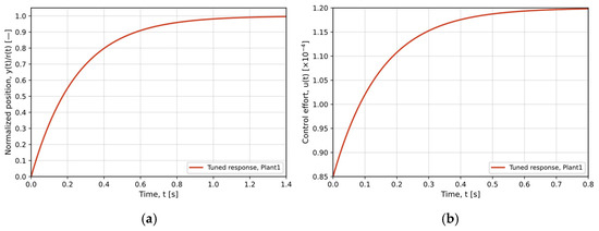
Similarly to the design of the previous controllers, the PID controller for the level tank used a parallel structure and was tuned using the MATLAB PID Tuner, employing the discrete model for the plant and considering a sampling time of s. The mathematical model for the PID controller used is presented in (11) and (12) for continuous time and discrete time, respectively. With the values of , , and , the response of the controlled system is shown in Figure 12.
Figure 12.
Closed-loop PID controller response for level plant.
The discrete representation of the PID controller shown in (12) was not converted to its corresponding difference equation because the implementation of this real-time control strategy was carried out using the Embedded Coder in Simulink/MATLAB R2025b.
4. Results
This section presents the results of the simulation and implementation of digital controllers in different test plants. Validation of the experimental framework in this research was divided into two stages: The first focused on the simulation of the discrete models of the test plants and the controllers tuned using the MATLAB PID Tuner through the control loops shown in Figure 6, Figure 8 and Figure 11. Subsequently, the digital implementation of the controllers with the actual plants and the C2000 microcontroller was carried out using the Energia IDE 0101E0017, Code Composer Studio (CCS) 12.8.1, and Simulink/MATLAB R2025b tools.
4.1. Real Implementation of Digital Controller in the Second-Order System
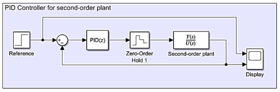
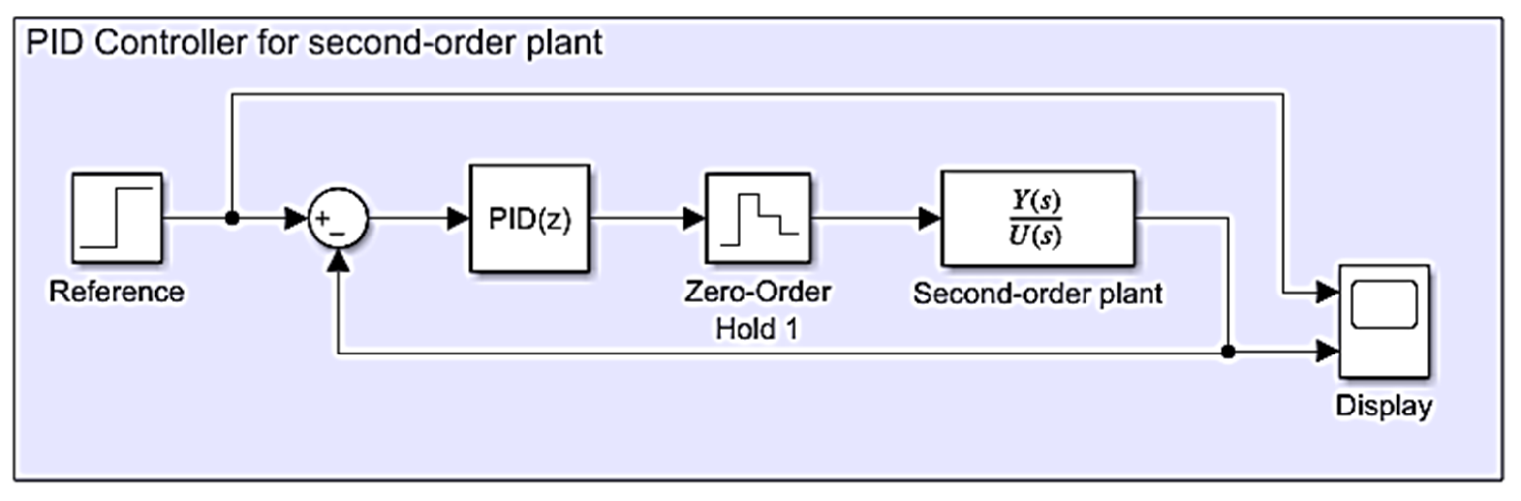
The simulation of the PID controller for the second-order plant was performed in Simulink/MATLAB R2025b based on the control loop presented in Figure 8. Simulink/MATLAB R2025b provides multiple approaches for system simulation such as transfer function-based models and differential equation-based representations, among others, with the selection depending on the specific objectives of the analysis. Figure 13 illustrates one possible implementation, considering a sampling time of 0.5 s, as specified in the previous section.
Figure 13.
Block diagram for PID controller in second-order plant.
The response of the control loop shown in Figure 13 is presented in Figure 14. The controller demonstrates a satisfactory response with respect to the design specifications, achieving 0% overshoot and a slightly reduced settling time. Subsequently, the digital PID controller was implemented on a C2000 microcontroller within the LAUNCHXL-F28379D embedded system using the Energia IDE 0101E0017. This development environment enables programming of various microcontrollers, including devices from Texas Instruments, in the C/C++ language in a manner similar to the Arduino framework [31].
Figure 14.
Simulated PID controller response for second-order plant.
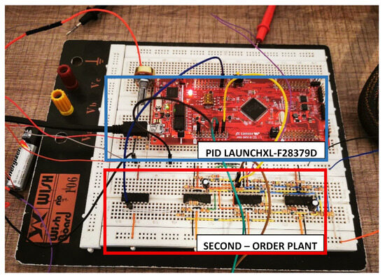
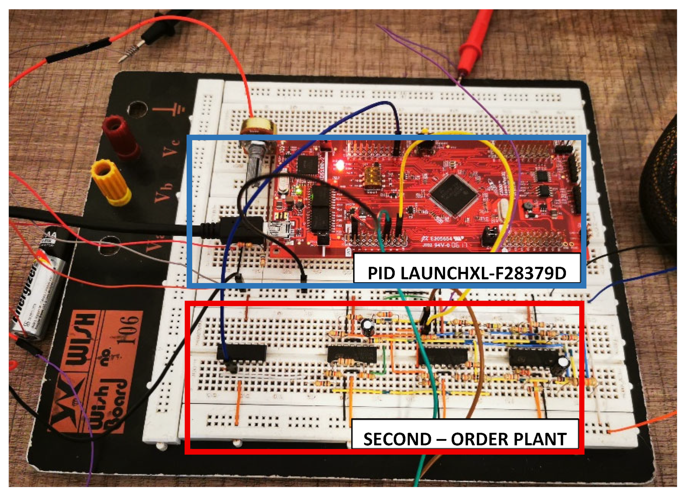
The PID controller was implemented in the C2000 microcontroller using the C programming language, with the defined functions and their corresponding implementations provided in Appendix A. To validate the operation of the PID controller on the second-order plant constructed using operational amplifiers and an ATX power supply, the control loop depicted in Figure 15 was implemented. Finally, real-time validation of the PID controller was carried out using an NI DAQ 6002 data acquisition device to visualize the plant response in MATLAB [32].
Figure 15.
Control loop implementation with the physical plant and the digital PID controller.
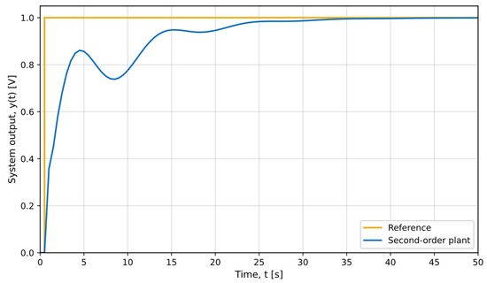
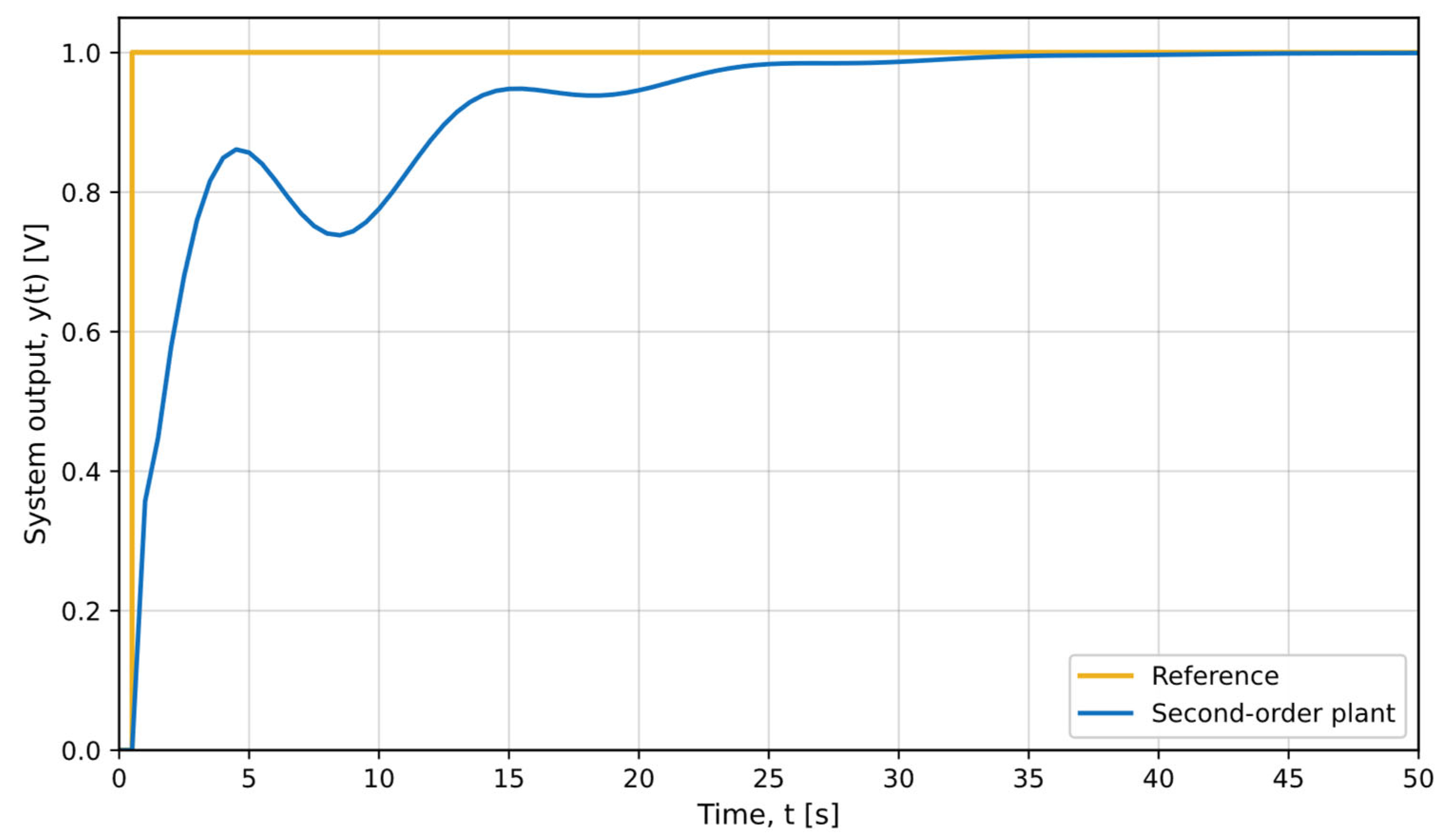
During the operational and validation tests on the digital controller using the control loop shown in Figure 15, the results presented in Figure 16 were obtained. The PID controller response closely matches the behavior previously observed in the simulation results.
Figure 16.
Real-time performance of the PID controller in the second-order plant.
4.2. Real Implementation of Digital Controller in the Flying Cutting System
The simulation and implementation of the PI controller for the flying cutting plant were performed based on the control loop shown in Figure 8. To validate the controller response at the simulation level, the block diagram illustrated in Figure 17 was implemented in Simulink/MATLAB R2025b, where the discrete PI controller and the flying cutting plant model are represented.
Figure 17.
Discrete-time control system for flying cutting plant.
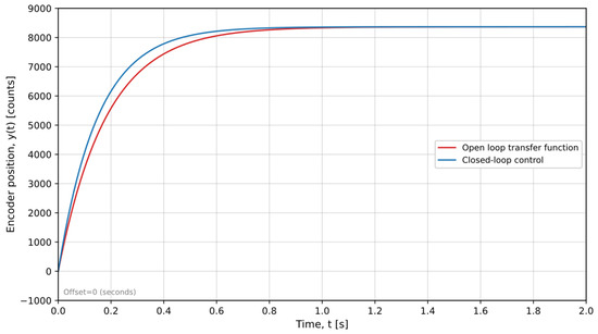
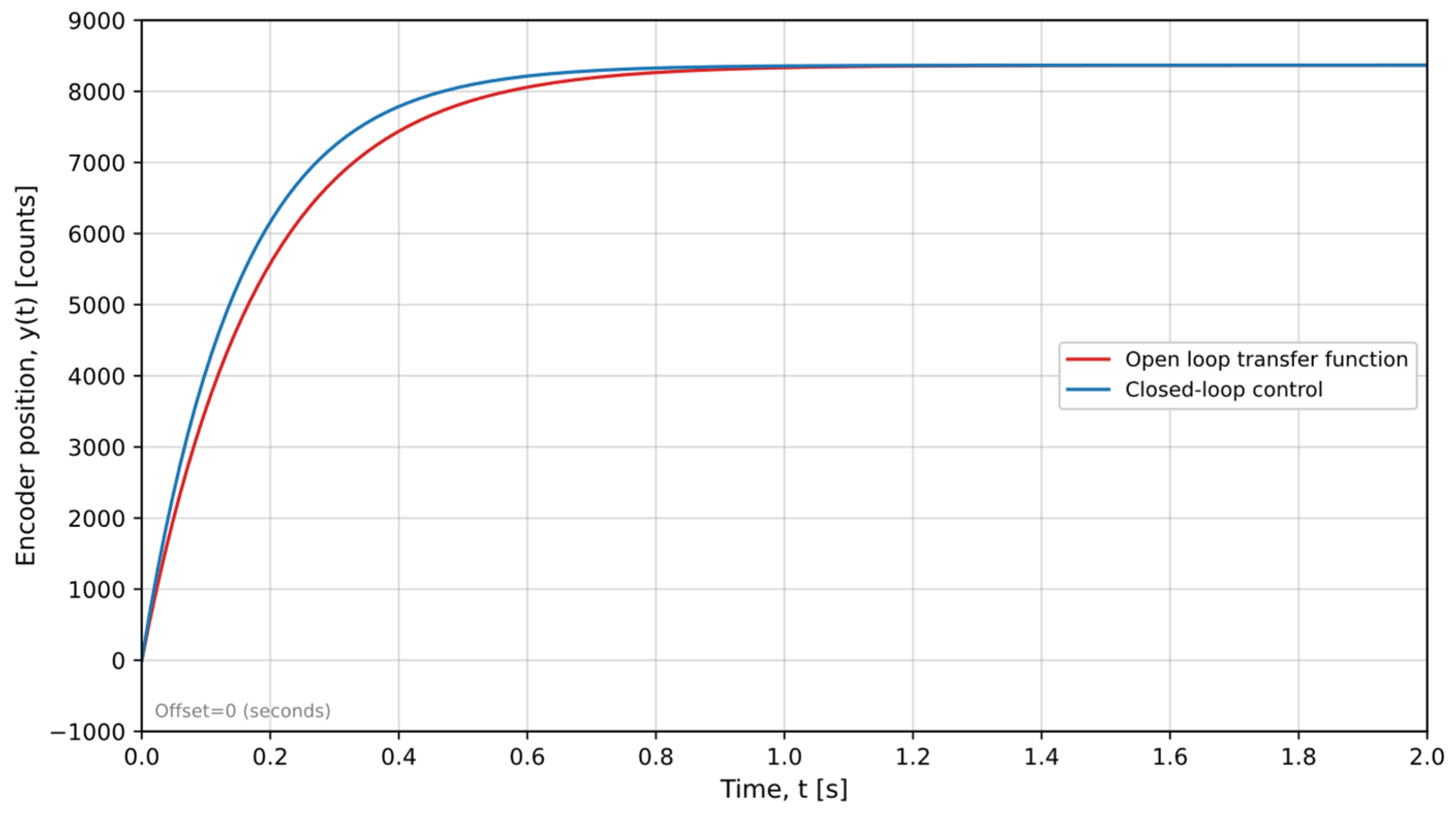
The simulation of the PI controller for the control loop shown in Figure 17 presented a response in line with the design conditions mentioned in the previous section, highlighting the ability of the MATLAB PID Tuner to tune controllers directly. Figure 18 shows the responses of the closed-loop PI controller and the open-loop plant.
Figure 18.
Response of PI controller simulation in flying shear plant.
Once the controller response was verified to be satisfactory, the digital controller was implemented on the TI C2000 microcontroller. In this case, Code Composer Studio (CCS) 12.8.1, a development environment provided by Texas Instruments for programming its microcontrollers, including the C2000 family of devices, was used, ensuring full support for the physical characteristics of embedded systems. CCS enables the development, compilation, and debugging of applications written in the C/C++ programming language. The PI controller was programmed using modular functions responsible for regulating the plant operation. The functionality of these modules, in combination with the controller’s discrete-time equations, facilitates the adjustments of motion-related parameters such as speed, direction, operating limits, and other relevant variables.
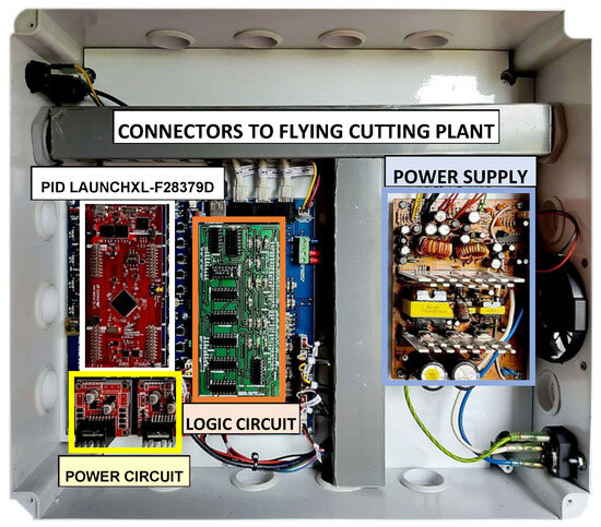
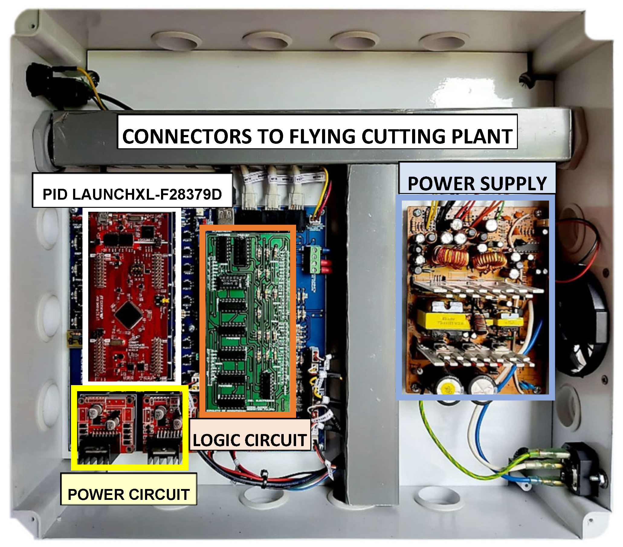
To validate the real-time performance of the PI controller in the flying cutting plant, the control loop shown in Figure 18 was implemented, as illustrated in Figure 19. This implementation employed the LAUNCHXL-F28379D embedded system, motor control, power circuits, signal activation, logic comparators and a power source with characteristics similar to those used in the second-order plant in order to ensure proper operation of the flying cutting plant shown in Figure 20.
Figure 19.
Implementation of the control loop for the flying cutting plant and the digital PI controller.
Figure 20.
Prototype of flying cutting plant used.
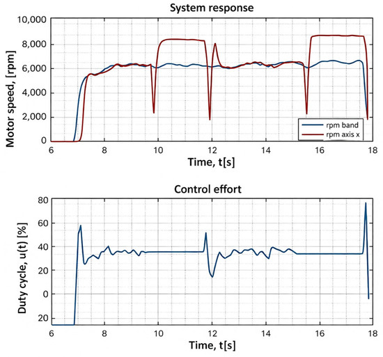
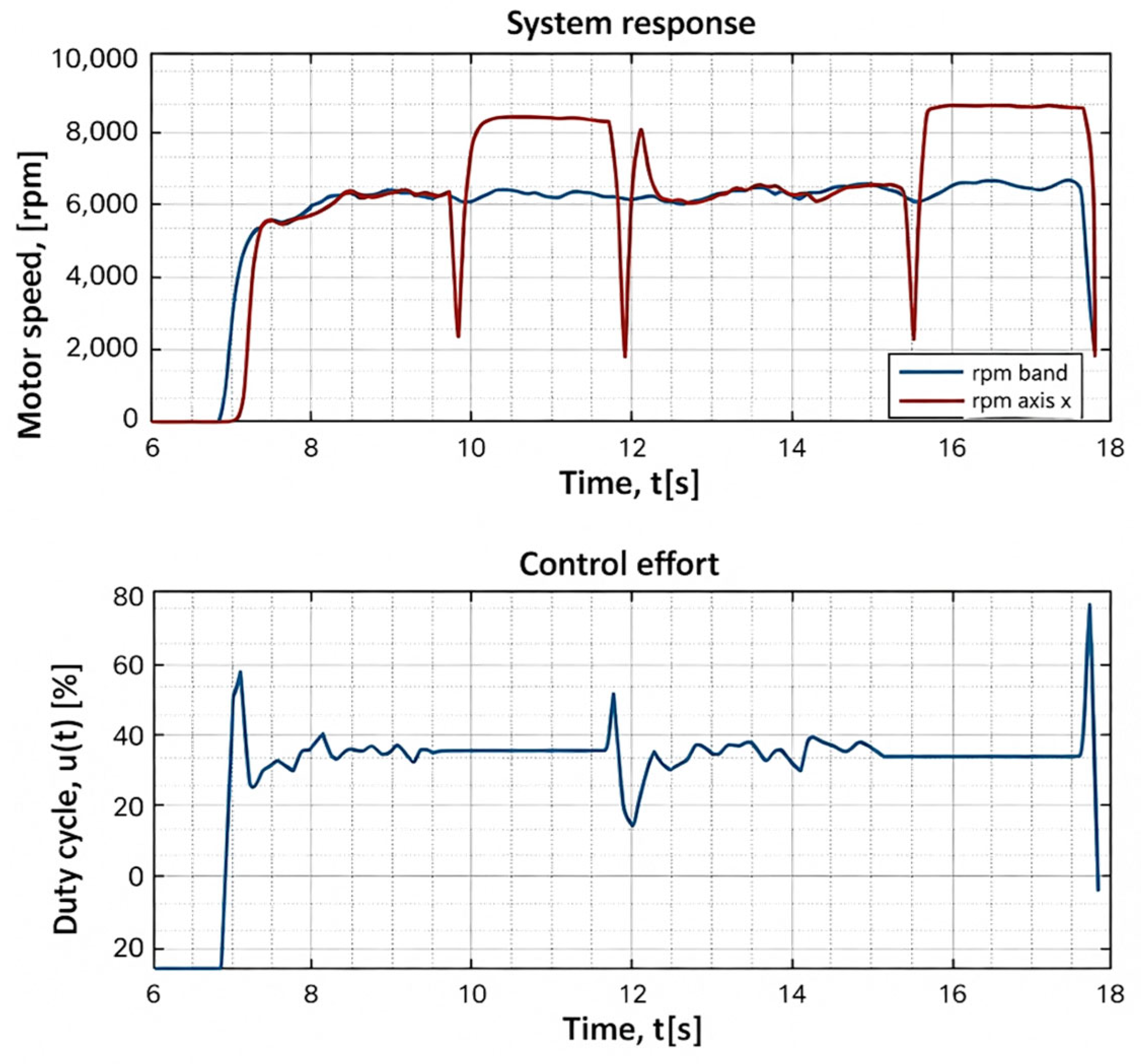
Finally, the validation and performance tests yielded the results presented in Figure 21. The system starts after 6.8 s and reaches a steady-state speed of approximately 6330 rpm within 1.8 s (blue trace in the upper plot in Figure 21). When the X-axis detects a change in the reference signal, a control effort is generated (blue trace in the lower plot in Figure 21), causing the gear motor to initiate its motion (red trace in Figure 21). The cutting operation occurs between 8 and 9.7 s, at which point the belt and X-axis speed are equal.
Figure 21.
Real-time performance of the PI controller in the flying cutting plant.
4.3. Real Implementation of Digital Controller in the Level Plant
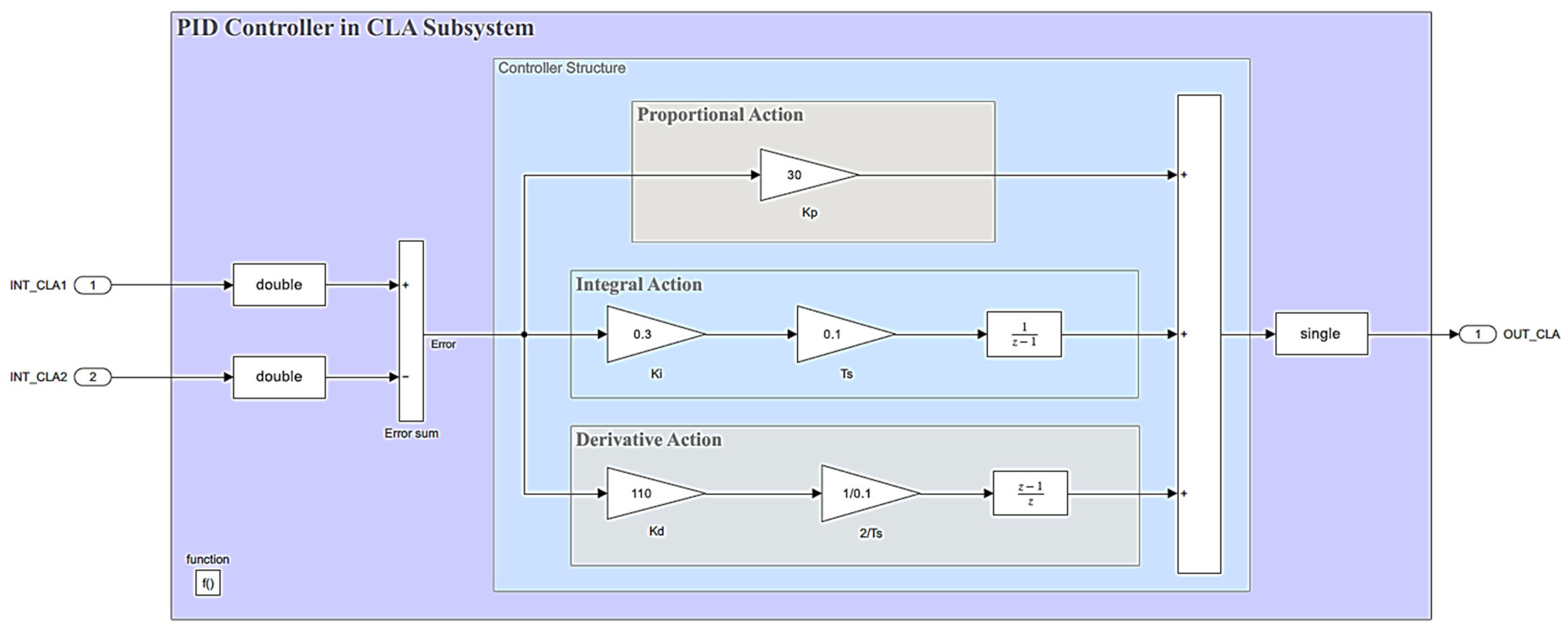
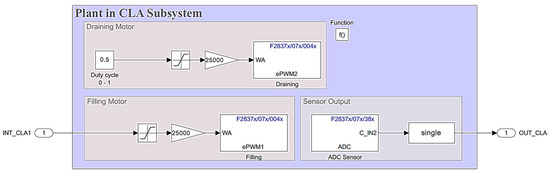
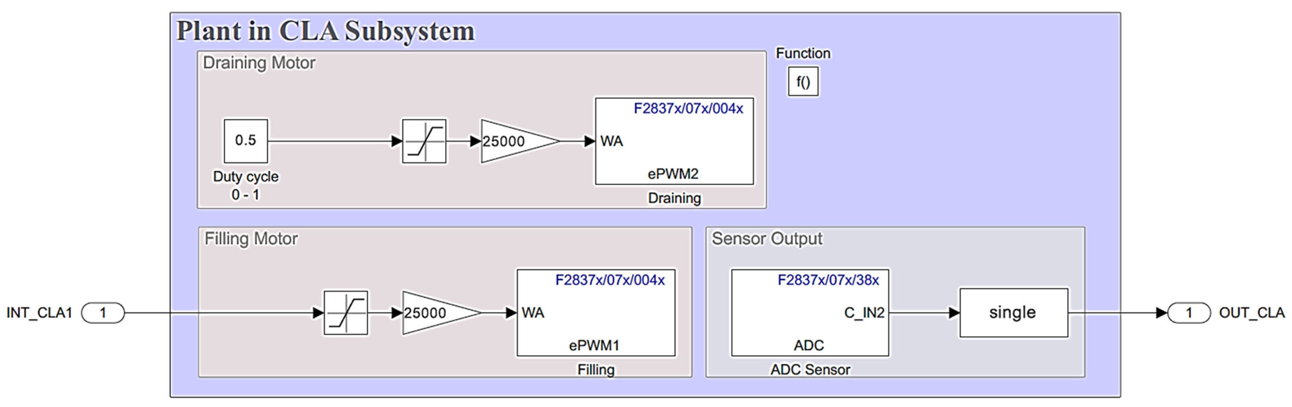
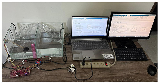
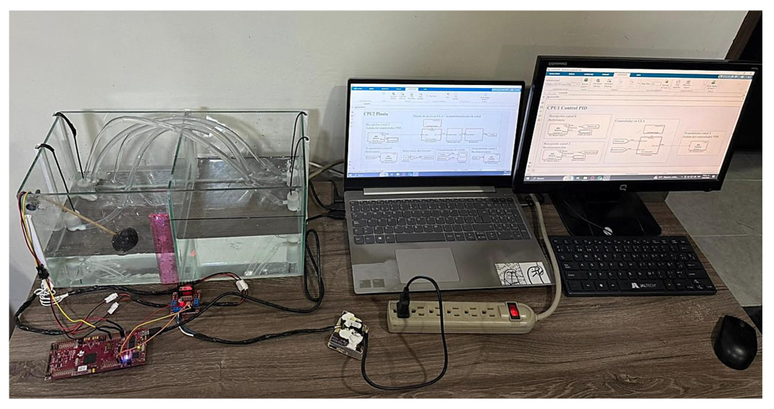
The control loop shown in Figure 11 for the level plant was implemented by configuring the CLA and the two CPUs of the C2000 microcontroller. Within the experimental and validation framework of this research, the PID controller was executed on CPU1, while data from the actuators and sensors of the physical plant were processed on CPU2. After defining the computational roles of each CPU, the CLA modules were configured to ensure parallel task execution within the microcontroller. The control algorithms were encapsulated using the CLA Subsystem block and triggered by the C28x CLA Task. Figure 22 and Figure 23 illustrate the control architecture for the level plant using the two CPUs available in the microcontroller.
Figure 22.
PID controller setup on CPU1.
Figure 23.
Level plant setup on CPU2.
Figure 22 illustrates the implementation of the parallel PID controller designed in the previous section. The controller error signal is obtained by subtracting the INT_CLA2 (feedback) signal from the INT_CLA1 (reference) signal. After the control signal (OUT_CLA) is computed, it is applied to the plant input (INT_CLA1), as shown in Figure 23. Once the plant output (OUT_CLA) is updated (see the same figure), it is fed back to the controller to update the error signal. The required system configurations were subsequently performed, as illustrated in Figure 24, and the Simulink/MATLAB R2025b integrated Code Generator was used to program the LAUNCHXL-F28379D LaunchPad and validate the real-time operation of the PID controller for the level plant.
Figure 24.
Implementation of control loop for level plant and digital PID controller.
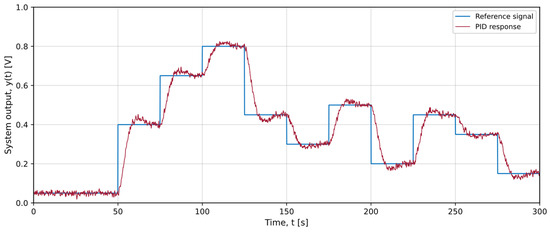
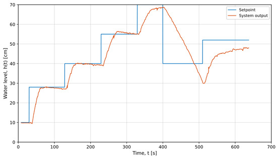
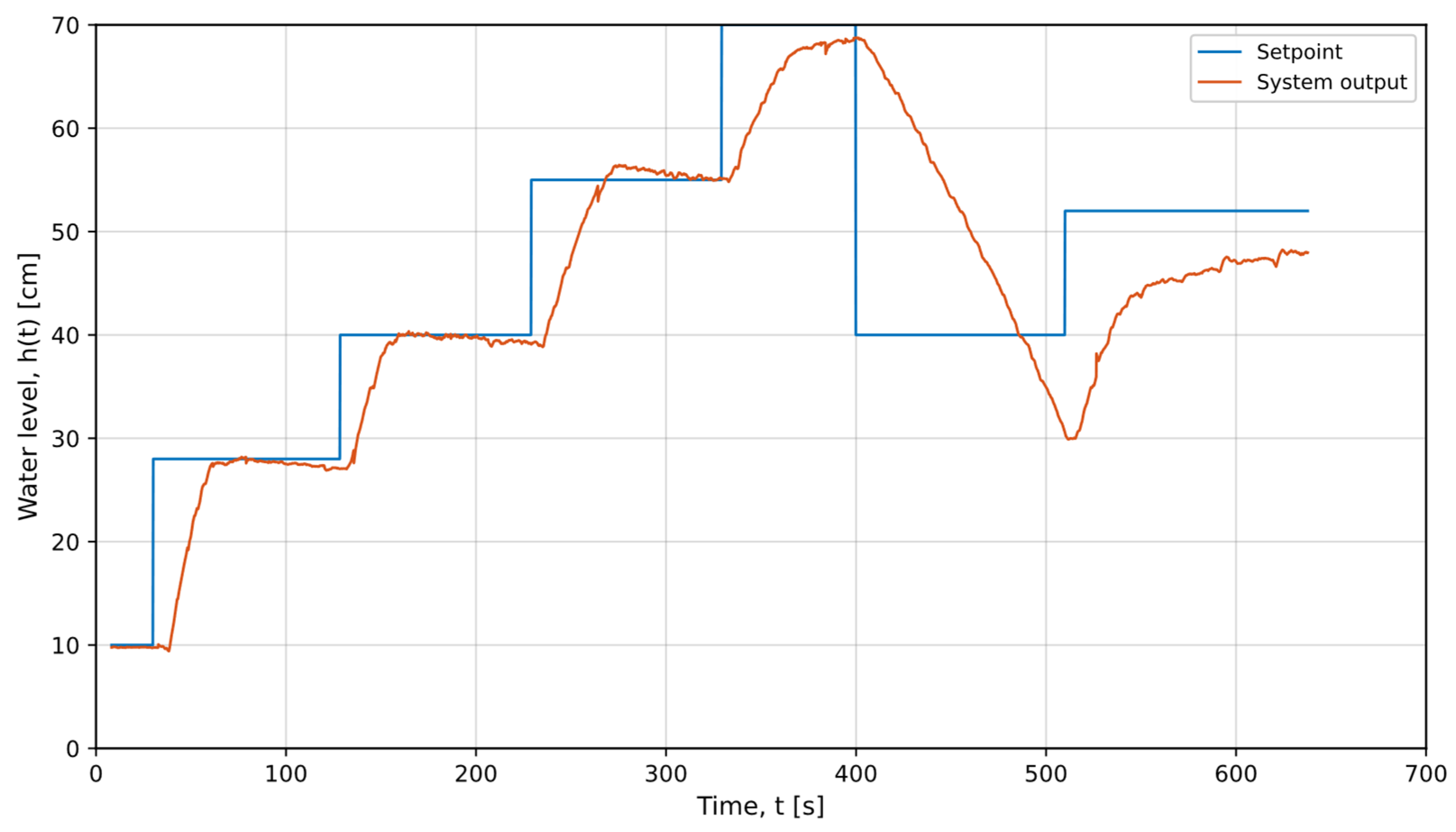
The performance achieved for the level plant using the real-time PID controller is presented in Figure 25. The controller responds effectively to reference changes, exhibiting 0% overshoot and a shorter settling time compared to the simulated system. This behavior is enabled by modules such as the CLA available in TI’s C2000 microcontrollers, which allow for parallel execution of the control law and simultaneous processing of plant signals.
Figure 25.
Real-time response of PID controller for level plant.
Additional characteristics obtained from the simulation and implementation results of the proposed controllers are quantitatively presented in Table 3.
Table 3.
A summary of the dynamic characteristics of the controllers in the test plants.
Table 3 shows the main differences between simulation and experimental implementation results. The most notable differences are presented in the level plant, and they can be attributed to several factors. The transfer function for the level process was obtained using off-line identification with System Identification Toolbox from MATLAB, where the response obtained corresponds to a linearized approximation of the system because the inherent nonlinearities of the plant components were not considered. Another important factor is that the implemented controller has high gains that can cause the control signal to exceed the physical limits of the actuators when reference changes occur. Additionally, the architecture used in the implementation of the digital controller helps reduce system latency and enables faster update rates for variables and sensors compared to the simulations.
Additionally, Table 3 presents the dynamic performance indicators obtained for the simulation and implementation of the digital controllers in each of the test plants. Among the reported indicators, the damping ratio (ζ) is not included, as this parameter is formally defined for second-order systems through their characteristic equation . In the research conducted, only the oscillatory plant corresponds to a second-order system, while the flying cutting plant is first-order and the level plant is third-order. For the latter systems, the damping ratio does not constitute a directly applicable characteristic parameter. Nevertheless, the dynamics of all plants are fully characterized by the indicators included in Table 3 and the procedural descriptions presented in the paper, which allow for an objective evaluation of the performance of the implemented controllers.
5. Conclusions
The research carried out presents a multi-platform reference framework for the implementation of digital control strategies using Texas Instruments C2000 microcontrollers. The main contributions are as follows:
- Development methodology: A comprehensive reference framework was developed that documents the implementation of real-time digital controllers across three development environments (Simulink/MATLAB R2025b, Code Composer Studio (CCS) 12.8.1, and Energia IDE 0101E0017). The work carried out provides researchers and educators with selection criteria based on the level of experience and application requirements, contributing to the existing literature where few works integrate multiple platforms using the same embedded system.
- Specific features of the C2000 hardware: The configuration and programming of the Control Law Accelerator (CLA) and the dual-core architecture of the TMS320F28379D microcontroller for parallel execution of control algorithms were demonstrated. The experimental results showed that this architecture achieved improvements in the settling times of the test plants used, highlighting the level system and emphasizing the importance of specific hardware for real-time control applications.
- Validated teaching material: Documented examples applicable to laboratory practices in the Electronic Engineering program at the University of Quindío were developed, facilitating the learning process for students with different levels of knowledge in embedded systems programming and digital control.
The advantages of using Texas Instruments C2000 microcontrollers for real-time control applications demonstrated in the research conducted include the following:
- Dedicated peripherals for control: The CLA module allows for parallel execution of control loops independently on different CPUs, reducing computational latency and improving control loop execution results.
- Processing capacity: The architecture of the TMS320F28379D microcontroller allows for simultaneous processing of control algorithms and plant I/O signals, as demonstrated in the level plant implementation. This makes these devices efficient alternatives for implementing control strategies using methodologies such as HIL or RCP.
- Multi-platform compatibility: Systems such as the LAUNCHXL-F28379D LaunchPad can be programmed through different programming environments, some with a high level of abstraction such as Energia IDE 0101E0017 and Simulink/MATLAB R2025b. Additionally, they can be programmed in lower-level development environments such as CCS, which is designed for the development of optimized industrial applications. The hardware features mentioned above contributed directly to the real-time performance of the control strategies proposed based on the experimental results. In particular, the level plant showed settling times of 30 s in the actual implementation compared to 200 s in simulation, demonstrating that dedicated hardware support exceeds predictions based on linear models. Regarding comparability with other platforms, microcontrollers without specialized modules such as the CLA are expected to exhibit higher latencies and lower determinism in control loop execution, although a comparative quantitative evaluation is proposed as future research.
Despite these results, the research conducted has some limitations. For example, only single-input, single-output (SISO) systems were considered, which restricts the applicability of the proposed framework to more complex multivariable processes. The control strategies implemented were limited to PI and PID controllers, without considering nonlinear, adaptive, or optimal control approaches. Additionally, the experimental evaluation was performed under a limited set of operating conditions in controlled environments, and the impact of disturbances, parameter variations, and measurement noise was not analyzed extensively.
Possible future work will address these limitations by extending the proposed reference framework to multivariable (MIMO) systems and exploring advanced control strategies such as state space control, model predictive control (MPC), optimal control, fuzzy logic, and nonlinear control techniques, taking advantage of the computational capabilities of the C2000 microcontroller architecture. Comparative evaluations with other microcontroller families will also be performed to assess scalability and portability between different hardware platforms.
Author Contributions
Conceptualization, D.F.R.-J., C.M.G.-A. and P.A.M.-G.; methodology, D.F.R.-J., C.M.G.-A. and P.A.M.-G.; software, D.F.R.-J., C.M.G.-A. and P.A.M.-G.; validation, D.F.R.-J., C.M.G.-A. and P.A.M.-G.; formal analysis, D.F.R.-J., C.M.G.-A. and P.A.M.-G.; investigation, D.F.R.-J., C.M.G.-A. and P.A.M.-G.; resources, D.F.R.-J., C.M.G.-A. and P.A.M.-G.; data curation, D.F.R.-J., C.M.G.-A. and P.A.M.-G.; writing—original draft preparation, D.F.R.-J., C.M.G.-A. and P.A.M.-G.; writing—review and editing, D.F.R.-J., C.M.G.-A. and P.A.M.-G.; visualization, D.F.R.-J., C.M.G.-A. and P.A.M.-G.; supervision D.F.R.-J., C.M.G.-A. and P.A.M.-G.; project administration, D.F.R.-J., C.M.G.-A. and P.A.M.-G.; funding acquisition, D.F.R.-J., C.M.G.-A. and P.A.M.-G. All authors have read and agreed to the published version of the manuscript.
Funding
This research was funded by Universidad del Quindío, grant number 100016837.
Data Availability Statement
The original contributions presented in this study are included in the article. Further inquiries can be directed to the corresponding author.
Conflicts of Interest
The authors declare no conflicts of interest.
Appendix A
The files for carrying out the simulations can be downloaded from https://drive.google.com/file/d/1BaKBtoO-EDzoRVm1Cfwt-BmyCpVDjLhv/view?usp=sharing (accessed on 15 December 2025).
References
- García, I.A. Teoría de Estabilidad y Control; Edicions de la Universitat de Lleida: Lérida, España, 2005. [Google Scholar]
- Ogata, K. Ingeniería de Control Moderna, 5th ed.; Pearson Educación: Madrid, Spain, 2010. [Google Scholar]
- Dorf, R.C.; Bishop, R.H. Modern Control Systems, 13th ed.; Pearson: Hoboken, NJ, USA, 2016. [Google Scholar]
- Leach, R. Digital control for embedded applications. In Proceedings of the Southcon/96 Conference Record, Orlando, FL, USA, 25–27 June 1996; IEEE: New York, NY, USA, 1996; pp. 18–22. [Google Scholar]
- Moallem, M. Design and implementation of computer control software: A low cost laboratory setup. IEEE Control Syst. 2005, 25, 26–29. [Google Scholar] [CrossRef] [Scilit]
- Chaber, P.; Lawrynczuk, M. Fast Analytical Model Predictive Controllers and Their Implementation for STM32 ARM Microcontroller. IEEE Trans. Ind. Inf. 2019, 15, 4580–4590. [Google Scholar] [CrossRef] [Scilit]
- Sun, Y.; Li, S.; Ramezani, M.; Balasubramanian, B.; Jin, B.; Gao, Y. DSP Implementation of a Neural Network Vector Controller for IPM Motor Drives. Energies 2019, 12, 2558. [Google Scholar] [CrossRef] [Scilit]
- Krause, N.; Di Gioia, A.; Brown, I.P. Multi-Core Microcontroller Hardware In the Loop System for Electric Machine Control. In Proceedings of the 2021 IEEE Energy Conversion Congress and Exposition (ECCE), Vancouver, BC, Canada, 10–14 October 2021; IEEE: New York, NY, USA, 2021; pp. 4711–4718. [Google Scholar]
- Belhamel, L.; Buscarino, A.; Cucuccio, A.; Fortuna, L.; Rascona, G. Model-Based Design Streamlines for STM32 Motor Control Embedded Software System. In Proceedings of the 2020 7th International Conference on Control, Decision and Information Technologies (CoDIT), Prague, Czech Republic, 29 June–2 July 2020; IEEE: New York, NY, USA, 2020; pp. 223–228. [Google Scholar]
- Ramírez-Jiménez, D.F.; Torres Valencia, C.A. Experimental Design and Simulation of a Fly-Cutting Plant for Academic Environment Practices. Machines 2024, 13, 15. [Google Scholar] [CrossRef] [Scilit]
- Srivastava, S.; Sukumar, V.; Bhasin, P.S.; Arun Kumar, D. A Laboratory Testbed for Embedded Fuzzy Control. IEEE Trans. Educ. 2011, 54, 14–23. [Google Scholar] [CrossRef] [Scilit]
- Kanagaraj, N.; Sivashanmugam, P. An Embedded Fuzzy Controller for Real Time Pressure Control. In Proceedings of the 2006 IEEE International Conference on Industrial Technology, Mumbai, India, 15–17 December 2006; IEEE: New York, NY, USA, 2006; pp. 2023–2027. [Google Scholar]
- Fang, Z.; Fu, Y. A networked embedded real-time controller for complex control systems. In Proceedings of the 2011 Chinese Control and Decision Conference (CCDC), Mianyang, China, 23–25 May 2011; IEEE: New York, NY, USA, 2011; pp. 3210–3215. [Google Scholar]
- Nuratch, S. A universal microcontroller circuit and firmware design and implementation for IoT-based realtime measurement and control applications. In Proceedings of the 2017 International Electrical Engineering Congress (iEECON), Pattaya, Thailand, 8–10 March 2017; IEEE: New York, NY, USA, 2017; pp. 1–4. [Google Scholar]
- Liu, X.; Zhao, X.; Gu, H.; Sanchez, A. Application and Design of Real-Time Control System for the Quad-rotor Helicopter. In Proceedings of the 2009 International Conference on Measuring Technology and Mechatronics Automation, Zhangjiajie, China, 11–12 April 2009; IEEE: New York, NY, USA, 2009; pp. 40–44. [Google Scholar]
- Werth, W.; Faller, L.; Liechtenecker, H.; Ungermanns, C. Low Cost Rapid Control Prototyping—A useful method in Control Engineering Education. In Proceedings of the 2020 43rd International Convention on Information, Communication and Electronic Technology (MIPRO), Opatija, Croatia, 28 September–2 October 2020; IEEE: New York, NY, USA, 2020; pp. 711–715. [Google Scholar]
- Thodsaporn, N.; Kinnares, V. Wind Turbine Simulator Equipped with Real-Time Monitoring and User-Friendly Parameter Setup Controlled by C2000 Microcontroller. In Proceedings of the 2020 17th International Conference on Electrical Engineering/Electronics, Computer, Telecommunications and Information Technology (ECTI-CON), Phuket, Thailand, 24–27 June 2020; IEEE: New York, NY, USA, 2020; pp. 713–716. [Google Scholar]
- Ramirez-Jimenez, D.F.; Parrado, A.L.; Medina, J.V. Overview of a framework for Implementation of digital controllers in Energia IDE using Texas Instruments microcontrollers. In Proceedings of the 2021 IEEE 5th Colombian Conference on Automatic Control (CCAC), Ibague, Colombia, 12–22 October 2021; IEEE: New York, NY, USA, 2021; pp. 13–18. [Google Scholar]
- Nadales, J.M.; Manzano, J.M.; Barriga, A.; Limon, D. Efficient FPGA Parallelization of Lipschitz Interpolation for Real-Time Decision-Making. IEEE Trans. Contr. Syst. Technol. 2022, 30, 2163–2175. [Google Scholar] [CrossRef] [Scilit]
- Martinez-Armero, Y.; Lopez-Blandon, S.; Giraldo, E. Optimal Control and Low-cost HIL Simulation of a Multivariable Interconnected Smartgrid. In Proceedings of the 2023 IEEE 6th Colombian Conference on Automatic Control (CCAC), Popayan, Colombia, 17–20 October 2023; IEEE: New York, NY, USA, 2023; pp. 1–6. [Google Scholar]
- Rahman, M.A.; Abushaiba, A.A.; Elrajoubi, A.M. Integration of C2000 Microcontrollers with MATLAB Simulink Embedded Coder: A Real-Time Control Application. In Proceedings of the 2024 7th International Conference on Electrical Engineering and Green Energy (CEEGE), Los Angeles, CA, USA, 28 June–1 July 2024; IEEE: New York, NY, USA, 2024; pp. 131–136. [Google Scholar]
- Xuelei, S. The Design of Digital Control System for Bio-fermentation Process Based on Embedded ARM9. In Proceedings of the 2025 IEEE 8th Advanced Information Technology, Electronic and Automation Control Conference (IAEAC), Guiyang, China, 8–10 August 2025; IEEE: New York, NY, USA, 2025; pp. 389–393. [Google Scholar]
- Reusser, C.A.; Herrera, R. Model Predictive Control Scheme of a Four-Level Quasi-Nested Converter Fed AC-Drive, with dc-Link Voltage-Drift Compensation. Electronics 2022, 11, 333. [Google Scholar] [CrossRef] [Scilit]
- Schluse, M.; Priggemeyer, M.; Atorf, L.; Rossmann, J. Experimentable Digital Twins—Streamlining Simulation-Based Systems Engineering for Industry 4.0. IEEE Trans. Ind. Inf. 2018, 14, 1722–1731. [Google Scholar] [CrossRef] [Scilit]
- Aatab, S.; Freitag, F. Towards a Library of Deep Neural Networks for Experimenting with on-Device Training on Microcontrollers. In Proceedings of the 2023 IEEE 9th World Forum on Internet of Things (WF-IoT), Aveiro, Portugal, 12–27 October 2023; IEEE: New York, NY, USA, 2023; pp. 1–6. [Google Scholar]
- Kumar, K.N.N.A.; Kurian, C.P. Model based control using C2000 microcontroller. In Proceedings of the 2014 International Conference on Advances in Energy Conversion Technologies (ICAECT), Manipal, India, 23–25 January 2014; IEEE: New York, NY, USA, 2014; pp. 13–20. [Google Scholar]
- Productos. Available online: https://rishbin.com/ (accessed on 5 July 2024).
- Kuo, B.C. Sistemas de Control Automático, 1st ed.; Prentice Hall Hispanoamericana: Mexico City, Mexico, 1996. [Google Scholar]
- Ramírez-Jiménez, D.F. Proposal of a Flying-Cutting Plant for the Development of Control Systems in Academic Environments. Cienc. Ing. Neogranadina 2025, 35, 87–112. [Google Scholar] [CrossRef] [Scilit]
- Ogata, K. Discrete-Time Control Systems, 2nd ed.; Pearson Education: Chennai, India, 2015. [Google Scholar]
- Bennia, I.; Baghli, L.; Jamshidpour, E.; Mechernene, A.; Martin, J.-P.; Yousfi, D. Real-Time Power electronics Control and Monitoring with TI F28379D DSC and GUI Composer. arXiv 2025, arXiv:2509.25008. [Google Scholar] [CrossRef] [Scilit]
- Hasman, M.; Phung, M.; Feng, Z.; Jatskevich, J. Microcontroller Implementation of Lookup-Tablebased Hall Sensor Correction for Improving Dynamic Performance for Brushless DC Motors. In Proceedings of the 2025 7th Global Power, Energy and Communication Conference (GPECOM), Bochum, Germany, 11–13 June 2025; IEEE: New York, NY, USA, 2025; pp. 300–305. [Google Scholar]



Disclaimer/Publisher’s Note: The statements, opinions and data contained in all publications are solely those of the individual author(s) and contributor(s) and not of MDPI and/or the editor(s). MDPI and/or the editor(s) disclaim responsibility for any injury to people or property resulting from any ideas, methods, instructions or products referred to in the content. |
© 2026 by the authors. Licensee MDPI, Basel, Switzerland. This article is an open access article distributed under the terms and conditions of the Creative Commons Attribution (CC BY) license.