


Abstract
To address limited permeability enhancement caused by insufficient free faces during static fracturing in low-permeability coal seams, this study investigated the No. 2 coal seam of the 32203 working face in Hanzui Coal Mine. A coupled stress–damage–seepage fluid–solid model was developed, and COMSOL Multiphysics 6.0 was used to compare stress, plastic zone, and gas pressure evolution under single-borehole and grid-pattern multi-borehole fracturing. Simulations showed that single-borehole fracturing was constrained by the free face, with limited lateral plastic-zone expansion (0.45 m) and non-uniform distribution due to in situ stress and coal anisotropy. In grid-pattern fracturing, drainage boreholes provided multiple free faces; superimposed expansion stresses connected plastic failure zones around fracturing boreholes, enlarging pressure relief. Field tests with six fracturing and six observation boreholes, using stable flow after secondary sealing as baseline and excluding sealing improvement, showed mixed drainage flow increased by 2.5–3.1 times and pure-gas flow by 2.1–2.5 times; pure flow at 0.6 m from a fracturing borehole rose from 0.0046 to 0.018 m3/min. Permeability enhancement was significant at spacing ≤1.6 m, consistent with simulations. Grid-pattern static fracturing expanded the fracture network via stress–damage–seepage coupling, providing a theoretical basis and parameter reference for efficient permeability enhancement in low-permeability coal seams.
1. Introduction
Coal seams in China generally exhibit low permeability. As mining depth increases, stress rises, permeability declines, and the risk of gas disasters intensifies [1]. Although gas drainage is a fundamental measure, its efficiency in low-permeability coal seams remains low, which necessitates effective permeability-enhancement technologies. China’s “15th Five-Year Plan” [2] and the “Coalbed Methane Development and Utilization Plan” [3] both emphasize co-mining and efficient gas utilization, making the improvement of drainage efficiency an urgent need.
Static fracturing (silent blasting) is a simple and safe technique. It uses static fracturing agents that hydrate to generate an expansion stress of 30–50 MPa, thereby fracturing coal and rock [4,5]. Its main component is CaO, which hydrates into Ca(OH)2 accompanied by volume expansion; when the expansion stress exceeds the tensile strength of coal, cracks initiate around the boreholes. Compared with conventional explosive blasting, static fracturing produces no blasting noise, flyrock, or shock waves [6], thus making it suitable for confined underground environments.
Extensive research has been conducted on static fracturing. With regard to energy-release mechanisms, Ref. [7] established a mechanical model to analyze the effects of water–cement ratio and soaking time, and Ref. [8] experimentally revealed expansion-cracking characteristics under different loading states. In terms of borehole layout optimization, Ref. [9] found that cracks propagate toward the nearest free face, and Ref. [5] established a stress–damage coupling model, revealing that double-hole fracturing relies on stress superposition and that guide holes utilize free faces to promote crack propagation. Concerning monitoring, Ref. [10] divided static blasting fracturing into micro-cracking, expansion pressure transfer, and splitting stages, and Ref. [11] determined through field experiments that the reasonable borehole spacing-to-diameter ratio is approximately 14–15. In addition, Ref. [12] studied static expansion fracturing of hard rocks in coal measures, and Ref. [13] proposed a combined hydraulic fracturing and static expansion method that increased permeability by a factor of 3.7.
Permeability evolution is a core indicator for evaluating permeability enhancement. Various permeability models have been established: Ref. [14] developed a permeability model for damaged coal based on a “cubic” model; Ref. [15] studied gas adsorption–desorption and seepage characteristics before and after hydraulic fracturing; Ref. [16] investigated permeability evolution under different confining pressures; and Ref. [17] used acoustic emission to reveal stress–strain–permeability responses. Regarding theoretical models, Ref. [18] considered effective stress and matrix shrinkage; Ref. [19] proposed an analytical model for pore pressure and stress changes; Ref. [20] established an anisotropic permeability model; and Ref. [21] developed a stress–damage–seepage coupling model applied to static fracturing simulation. Regarding multi-field coupling, Ref. [22] established a damage constitutive model based on Weibull and D-P criteria; Ref. [23] characterized fracture systems using fractal theory; and Ref. [24] proposed a permeability model considering temperature, effective stress, and damage.
Numerical simulation is an important approach to reveal the evolution of stress, damage, and seepage fields during static fracturing. Ref. [25] demonstrated that an expansion stress of 40 MPa, a borehole diameter of 75 mm, and a borehole spacing of 0.5 m can effectively fracture low-permeability thick coal seams, increasing permeability by a factor of approximately 50. Ref. [26] used COMSOL to optimize borehole spacing for gas drainage along the coal seam, and Ref. [27] established a multi-field coupled drainage model. Furthermore, CO2 phase-transition fracturing [28] also provide valuable references for static fracturing.
However, most existing studies focus on fracturing-agent energy release, borehole layout, and fracture-development characteristics, while research on stress superposition, fracture evolution, and dynamic gas-seepage response under multi-hole fracturing remains insufficient. In contrast to double-hole fracturing, which relies on inter-hole stress superposition and uses a single free face to guide cracks, grid-pattern borehole layout employs multiple drainage boreholes as free faces, thereby creating multi-directional stress superposition and plastic-zone connectivity that can significantly expand the pressure-relief and permeability-enhancement range. For conditions with insufficient free faces, the creation of multiple free faces and the expansion of the permeability-enhancement range through grid-pattern borehole layout still lack systematic theoretical and numerical simulation support. Given the emphasis of the “15th Five-Year Plan” on the co-mining of coal and gas [1,2], research on the permeability enhancement mechanism of static fracturing and borehole parameter optimization is of great theoretical and practical significance for efficient gas drainage in low-permeability coal seams.
The coal samples used in this study were collected from freshly exposed underground coal masses and were immediately sealed, shielded from light, and tested promptly. Thus, they did not undergo long-term oxidation or weathering; accordingly, the model parameters were selected under the assumption that the coal samples remained in their original state [29]. To address the above issues, this study is set against the engineering background of the No. 2 low-permeability thick coal seam in the 32203 working face of Hanzui Coal Mine. Based on fluid–solid coupling theory, a model of coal seam deformation–failure and gas migration is constructed. COMSOL Multiphysics is used to compare the evolution of stress, the plastic zone, and gas pressure between single-hole and grid-pattern multi-hole fracturing. The results reveal the controlling role of free-face density in permeability enhancement and the directional evolution of fracture networks. On this basis, the parameters of grid-pattern static fracturing boreholes are optimized, and field tests verify the reliability of the simulation results. These findings provide a theoretical basis and technical reference for efficient permeability enhancement in low-permeability thick coal seams.
2. Theoretical Mechanism of Static Fracturing for Coal Seam Permeability Enhancement and Gas Drainage Promotion
Static fracturing technology, also referred to as silent blasting, is a technique in which the expansion pressure generated by the volume expansion of a water-mixed static fracturing agent fractures the borehole wall. This technology offers the advantages of producing no flyrock, blasting noise, shock waves, or vibrations. It is easy to operate and highly safe, showing promising prospects for application in the permeability enhancement of low-permeability coal seams. The main component of the static fracturing agent is quicklime (CaO). The fracturing effect of the static fracturing agent mainly depends on the chemical reaction between CaO and water to produce Ca(OH)2. During this reaction, heat is released, and the volume gradually expands. The expansion stress induced by this volume increase acts on the borehole wall, subjecting the connected parts to tensile stress. Once the tensile stress exceeds the ultimate tensile strength of the coal mass, cracks initiate in the surrounding rock of the borehole. The reaction equation for CaO with water is as follows:
When lime is mixed with water, the surfaces of the CaO particles hydrate immediately, forming Ca(OH)2. Ca(OH)2 crystallizes into a layered structure, in which each layer adopts a hexagonal close-packed arrangement, while the chemical bonds between adjacent layers are extremely weak. Once Ca(OH)2 dissolves in water to form a saturated solution, no further dissolution occurs; instead, it precipitates as a colloid, with the release of intense heat. As the interior of the lime particles absorbs water, the viscosity among colloidal particles increases, leading to coagulation. As water gradually evaporates, the solution becomes supersaturated, and Ca(OH)2 crystallizes and hardens. After crystallization and hardening, Ca(OH)2 reacts with CO2 in air to form CaCO3, which increases the solid-phase volume and further enhances strength.
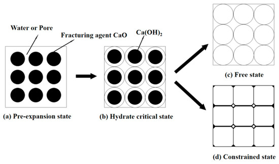
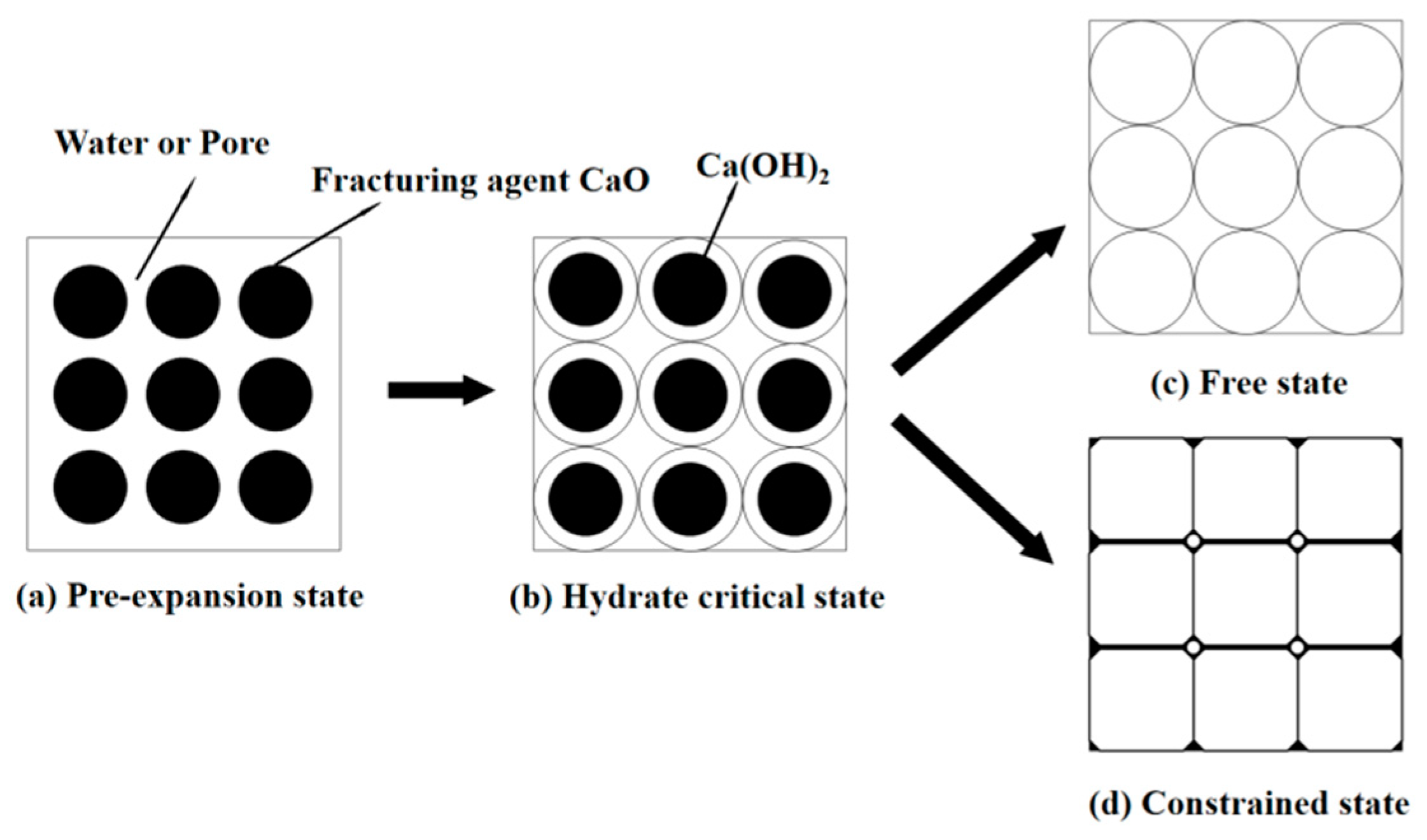
Under unconfined conditions, lime mixed with water expands to approximately twice its original volume, and its porosity increases correspondingly. This is merely a volumetric change; in the absence of confinement, the fracturing-agent slurry expands and disintegrates into powder. Under confined conditions, however, the volume of Ca(OH)2 increases, and the particles are compressed against one another, which reduces porosity and generates an expansion pressure of 30–50 MPa. The tensile strength of coal is far lower than this pressure. Therefore, as the expansion pressure gradually increases and exceeds the maximum strength that the confined space can withstand, the coal mass surrounding the borehole inevitably fails. Figure 1 shows the expansion model for the static fracturing agent.
Figure 1.
Schematic diagram of the expansion principle of the static fracturing agent.
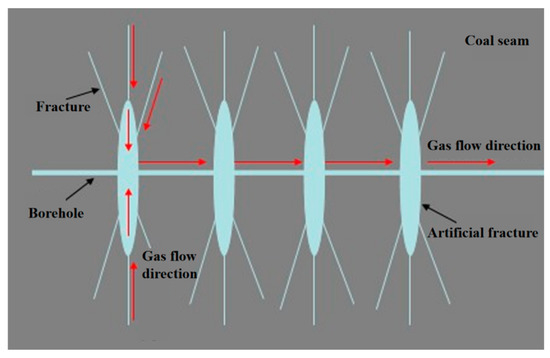
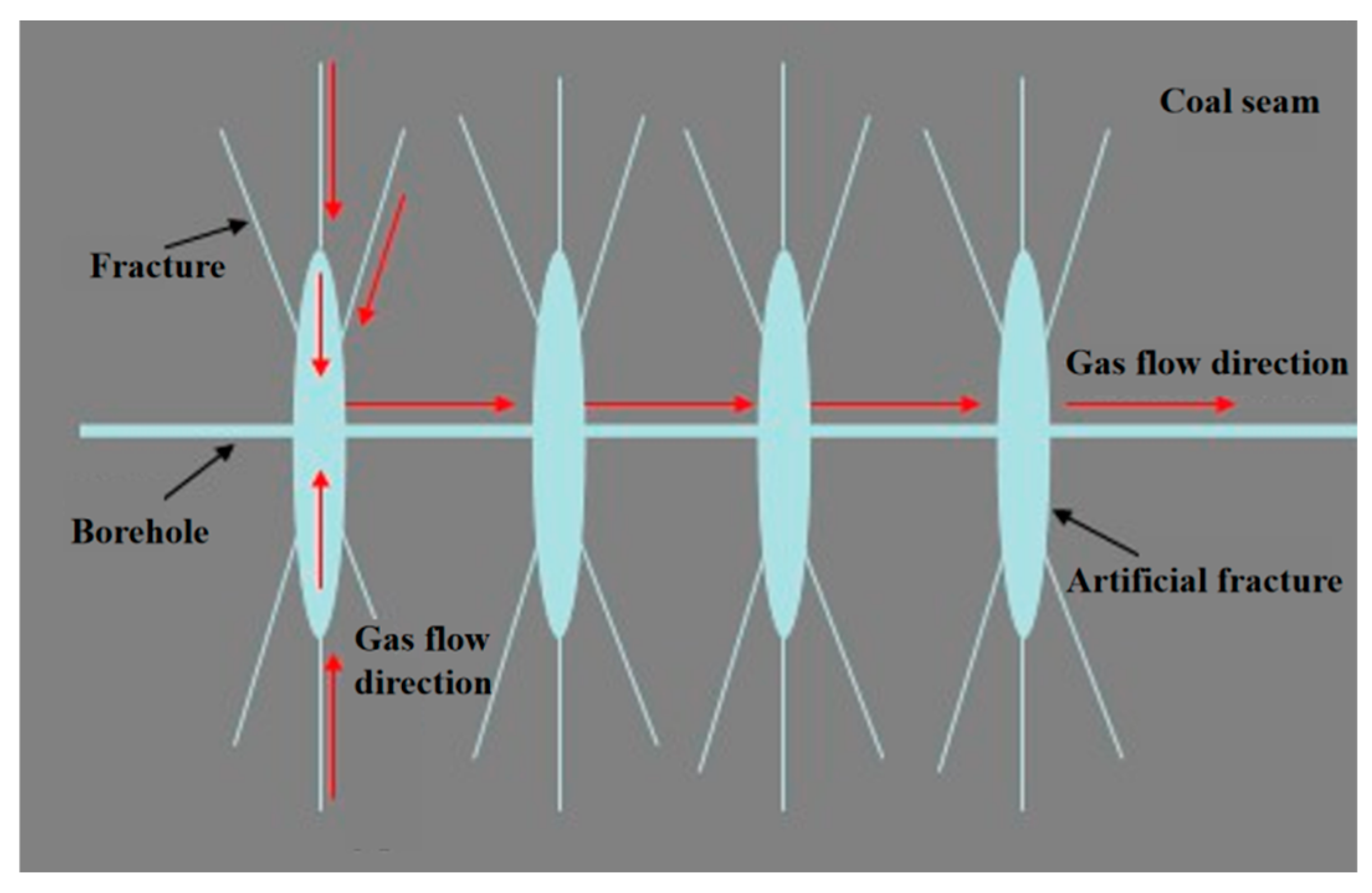
Static fracturing is a process in which, upon hydration of the fracturing agent, a radial expansion pressure far exceeding the ultimate strength of the surrounding coal mass is generated on the borehole wall, thereby efficiently generating localized fractures around the fracturing borehole and forming a fracture pressure-relief zone containing a complex fracture network within the coal seam. Within this fracture pressure-relief zone, fracture-induced damage to the coal mass, combined with gas diversion and permeability enhancement, results in new in situ stress, gas pressure, and gas-seepage fields under the influence of expanding fractures. Figure 2 shows the gas migration pathways after static fracturing. The static fracturing agent undergoes prolonged hydration, which results in a slow increase in expansion stress. Its loading rate is much lower than that under dynamic impact, indicating a quasi-static loading process. Therefore, pronounced stress wave propagation or reflection does not occur during static fracturing, and coal failure is primarily governed by quasi-static stress redistribution and tensile stress concentration induced by the expansion stress.
Figure 2.
Gas migration in coal seam after static fracturing.
After hydraulic fracturing, within the borehole pressure-relief zone, the artificial fractures interconnect with the original cleats and structural fractures in the coal mass, substantially enhancing coal seam permeability. Under negative pressure during gas drainage, free gas within the fracture zone flows rapidly through the fractures toward the gas drainage boreholes, where it is extracted to the surface. Meanwhile, the original equilibrium of the coal seam is disturbed, and adsorbed gas rapidly desorbs from and diffuses away from the coal-matrix surface, and ultimately flows continuously through the fracture network into the gas drainage system.
This study addresses the failure effect of the expansion stress generated by hydration of the static fracturing agent on the coal surrounding the boreholes by applying a radial load to the borehole wall and incorporating it into the governing equations for coal deformation. Once the expansion stress exceeds the tensile strength of the coal, the resulting fracture network and free-face effect are modeled using a plastic criterion to determine plastic-zone propagation and a permeability evolution equation to characterize the permeability enhancement induced by fracture connectivity. The desorption–diffusion–seepage process of gas within the fracture network is coupled and solved using the adsorption equation, Darcy’s law, and the continuity equation. Accordingly, the qualitative mechanism described in Section 2 is transformed into a quantitatively solvable mathematical model, providing theoretical support for the numerical simulation of permeability enhancement through grid-pattern static fracturing.
3. Numerical Simulation of Borehole Layout Optimization for Static Fracturing
According to the geological and gas occurrence conditions of the No. 2 coal seam in the 32203 fully mechanized mining face of Hanzui Coal Mine, a fluid–solid coupling model for borehole failure and gas flow in coal seams under static fracturing conditions was developed using the COMSOL Multiphysics 6.0 simulation software. The distribution characteristics of stress and plastic zones around boreholes were compared and analyzed for single-borehole, double-borehole, and network-pattern fracturing. The gas pressure-relief range of inspection boreholes was also simulated for different gas drainage durations, and a reasonable static fracturing borehole layout and gas drainage duration were identified to guide the field-test implementation of coal seam fracturing and permeability enhancement.
3.1. Basic Assumptions and Governing Equations of the Model
Multiple factors influence gas flow in coal seams, making it a relatively complex process. To simplify the solution, the following basic assumptions are made:
- ①
- The gas permeability of the coal seam roof and floor is relatively low, so the roof and floor can be regarded as impermeable strata.
- ②
- The coal skeleton is a linear elastic body, and the coal permeability is isotropic.
- ③
- The gas in the coal seam is treated as an ideal gas and obeys Darcy’s law.
- ④
- Gas seepage and desorption are treated as isothermal processes and follow the ideal gas equation.
- ⑤
- Coal failure satisfies the Mohr–Coulomb criterion.
- (1)
- Gas continuity equation
According to the law of conservation of mass, the continuity equation for gas flow in coal seams can be expressed as follows.
where ρg is the gas density, kg/m3; vg is the gas seepage velocity, m/s; Q is the gas content per unit volume of coal, m3; t is time, s.
The adsorbed gas content in coal seams follows the Langmuir equation. In the calculation, the effects of coal moisture content, ash content, and temperature on the adsorbed gas content are considered. The formula for calculating the adsorbed gas content per unit volume of coal, Q1, is
where c is the coal correction coefficient, which can be expressed as
where p is the coal seam gas pressure, MPa; a and b are Langmuir adsorption constants; Mad is the moisture content of coal, %; Aad is the ash content of coal, %; and ρ is the coal density, kg/m3.
The free gas content in coal seams is calculated based on the coal seam gas pressure and porosity. The expression for the free gas content per unit volume of coal, Q2, is
where ρg is the gas density, kg/m3; φ is the coal porosity, %; β is the gas compressibility coefficient, kg/(m3·MPa).
Q2 = ρgφ
Generally, free gas is considered an ideal gas. The total gas content in the coal seam, Q, can be obtained as
- (2)
- Gas seepage equation
If the gas flow in the coal seam is regarded as horizontal linear steady-state flow, it obeys Darcy’s law, and the relationship can be expressed as
where Vg is the gas seepage velocity, m/s; ηg is the gas dynamic viscosity coefficient, 1.08 × 10⁻⁵ Pa·s; k is the coal seam permeability, m2; ∇p is the gas pressure gradient, MPa/m.
Under low pore pressure conditions, the coal permeability needs to be corrected using the Klinkenberg formula, and the gas seepage velocity can be expressed as
where bp is the Klinkenberg coefficient. By rearranging, the gas migration continuity equation can be obtained as
- (3)
- Permeability variation equation
The fracture system surrounding the borehole serves as the primary pathway for gas migration in the coal seam. Since fractures are compressible, the fracture width in the coal–rock mass varies with the applied load. As the normal stress on the fractures increases, the fracture surfaces gradually close, and the fracture width progressively decreases, approaching a constant value. Permeability measurement experiments under full stress–strain conditions have confirmed that stress variations in any direction affect permeability. Therefore, the permeability change can be calculated using volumetric stress or mean stress, and the relationship between permeability k and applied stress is expressed as
where ka is the absolute permeability of the coal mass, m2; θ is the effective volumetric stress, MPa; bσ is the volumetric stress influence coefficient, MPa−1.
k = kaexp[−bσ(Δθ)]
After the gas flow field in the coal seam changes, an increase or decrease in gas pressure causes the coal matrix to undergo swelling or shrinkage, which affects the fracture width and thereby changes the coal permeability. Levine used a model of the same form as the Langmuir adsorption equation to describe the swelling of coal, namely
where εs is the volumetric strain of the coal mass; is the limiting volumetric deformation; and is the adsorption deformation pressure, MPa.
Considering the influence of pore pressure and adsorption deformation, Levine’s coal swelling model is adopted to describe the matrix shrinkage caused by pressure reduction, from which the following can be obtained:
where Φf is the effective porosity of the coal mass, %; cm, β are matrix compression coefficients, MPa−1; f is a coefficient, 0~1; K is the bulk modulus of the coal seam, MPa; E is the elastic modulus of the coal seam, MPa; M is Lame constants; v is Poisson’s ratio; and k0 is the initial permeability of the coal mass, m2.
Considering the in situ stress, expansion force disturbance, and gas pressure changes, the permeability evolution equation can be obtained by combining the above equations and can be expressed as
- (4)
- Deformation control equation of coal mass
Assuming the coal seam is an elastic body, the constitutive equation for coal deformation can be expressed as
where e is the volumetric deformation; εij is the volumetric strain; δij is the Kronecker delta.
σij = λσije + 2Gεij(i,j = 1,2,3)
The strain in the coal–rock mass ε consists of two components: the strain caused by the change in in situ stress εd (according to Hooke’s law) and the strain caused by the change in free gas pressure εp. Therefore, the following can be obtained:
After rearrangement, the following can be obtained:
where α is the pore gas pressure coefficient; Fi is the volumetric stress, MPa.
The seepage coupling equation for gas migration in coal seams under static fracturing conditions can be obtained as
3.2. Model Construction and Parameter Settings
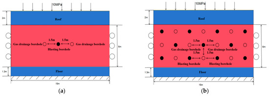
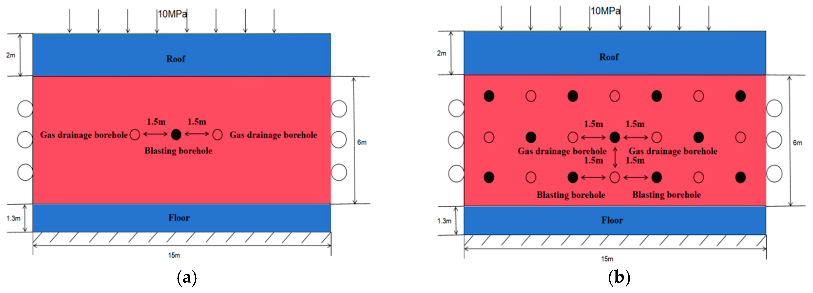
The average burial depth of the 32203 working face in Hanzui Coal Mine is 400 m, and the average coal seam thickness is 6.5 m. Figure 3 shows the established models for enhanced gas drainage via single-borehole and multi-borehole static fracturing. Zero-flux boundaries were applied around the model, and the coal seam roof and floor were considered impermeable strata. Roller support boundaries were applied on the left and right sides, the bottom of the model was fixed, horizontal constraints were applied to the side faces, and the top of the model was a free boundary. A vertical downward stress of 10 MPa was applied to the top free boundary to represent the overburden load. Based on the laboratory-measured expansion stress of the static fracturing agent, a load of 40 MPa was applied to the borehole wall to represent the expansion force generated by static fracturing. The initial velocity and displacement fields were set to zero; the gas drainage pressure was set to −20 kPa; and the borehole diameter was 75 mm. The model is a two-dimensional plane-strain model with dimensions of 6 m × 3 m. The mesh consists of free triangular elements with local refinement, with a total of approximately 21,000 elements. A fully coupled solver in COMSOL was adopted using the PARDISO solver with a relative tolerance of 1 × 10⁻⁶. Transient adaptive time-stepping was used, with an initial step of 0.01 d and a maximum step of 1 d. The specific model parameters are listed in Table 1.The lithological characteristics of the roof and floor of the working face are presented in Table 2.
Figure 3.
Geometric model of static fracturing for enhanced gas drainage. (a) Single-borehole fracturing model. (b) Multi-borehole fracturing model.
Table 1.
Basic parameters of the static fracturing enhanced gas drainage model for No. 2 coal seam.
Table 2.
Description of strata in the working face.
3.3. Analysis of Numerical Simulation Effects of Static Fracturing for Permeability Enhancement
- (1)
- Single-borehole fracturing effect
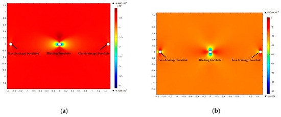
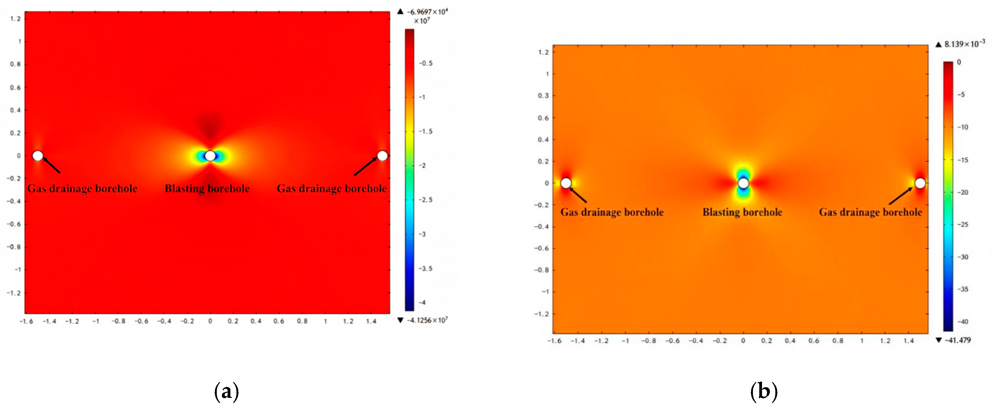
Figure 4 shows the stress distribution around a single static fracturing borehole. As shown in Figure 4a, since the drainage borehole diameter is small, its pressure-relief range is relatively limited. As the expansion load applied to the fracturing borehole wall increases, the influence range of horizontal stress around the fracturing borehole becomes significantly larger than that around the drainage borehole. Pronounced stress concentrations appear on the left and right sides of the fracturing borehole, with the peak stress reaching 41.26 MPa, and the stress gradually migrates toward the deeper coal seam. In contrast, stress-reduction zones appear on the upper and lower sides of the fracturing borehole. As shown in Figure 4b, a vertical stress concentration occurs on the upper and lower sides of the fracturing borehole, and the stress influence range of the fracturing borehole is significantly larger than that of the inspection borehole. Pressure-relief zones appear on the left and right sides of the fracturing borehole. This occurs because, during static fracturing, when the radial expansion force applied to the borehole wall exceeds the ultimate tensile strength of the surrounding coal mass, the coal mass fractures, generating numerous cracks and thereby relieving pressure.
Figure 4.
Stress distribution around boreholes after static fracturing. (a) Horizontal stress distribution around the borehole. (b) Vertical stress distribution around the borehole.
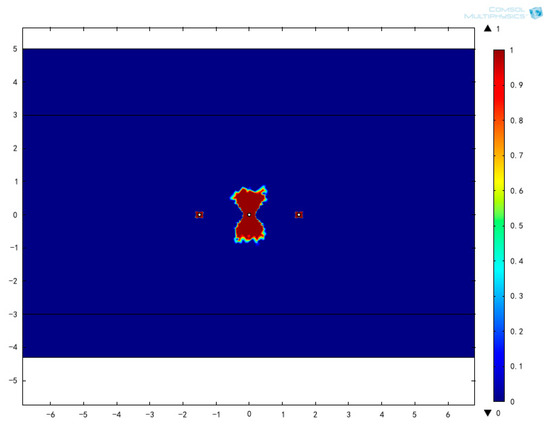
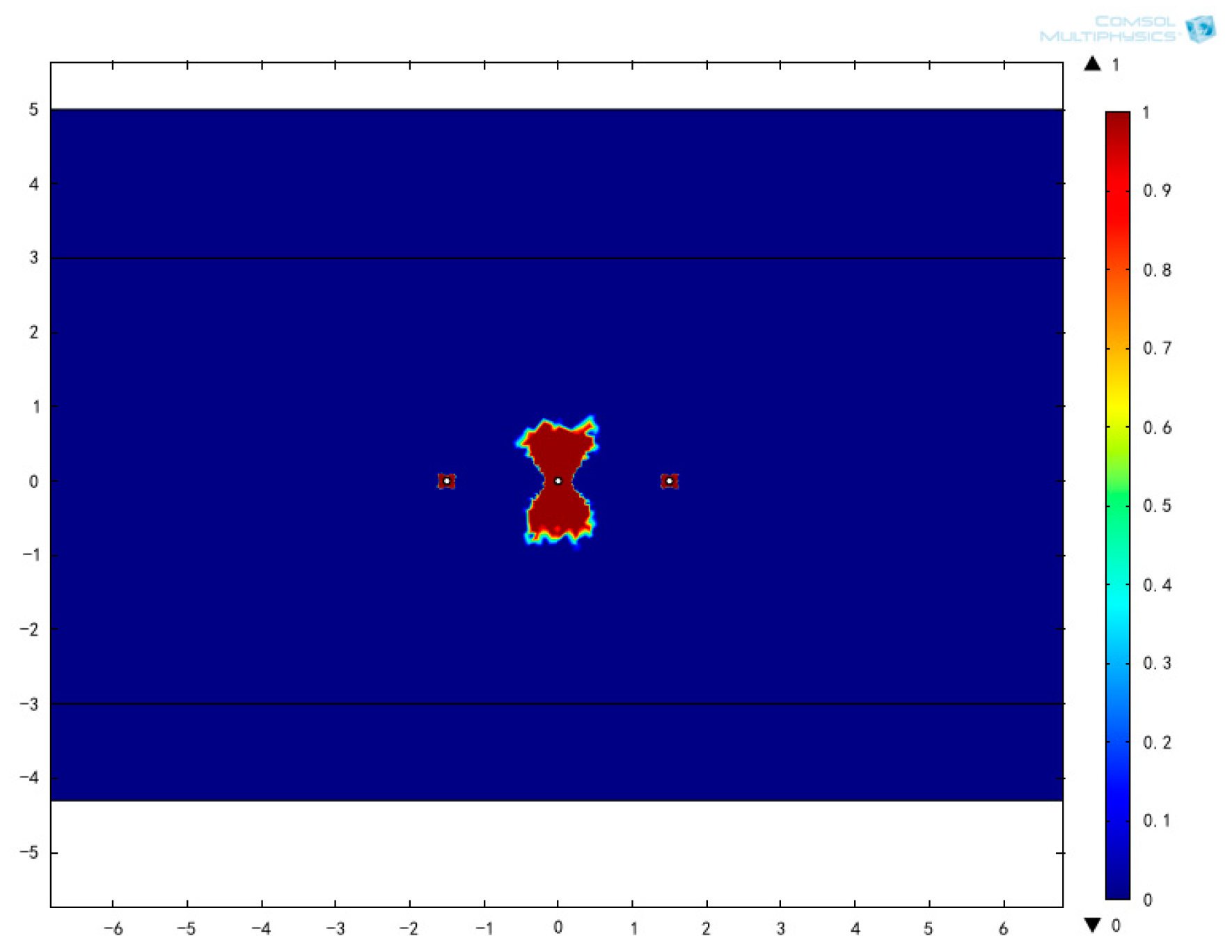
Figure 5 shows the distribution of plastic zones around the boreholes. The plastic zone around the fracturing borehole is significantly larger than that around the gas drainage borehole. The plastic zone around the fracturing borehole is spindle-shaped, extending laterally approximately 0.45 m on both the left and right sides, 0.729 m upward, and 0.740 m downward. The plastic zone around the gas drainage borehole is butterfly-wing-shaped, with a plastic zone radius of approximately 0.12 m. This indicates that once the expansion force is applied to the fracturing borehole wall, significant plastic deformation occurs in the coal mass surrounding the borehole, greatly promoting the development of coal seam fractures and substantially improving the permeability of the coal mass in this zone.
Figure 5.
Plastic-zone distribution after single-borehole fracturing.
The plastic zone under single-borehole fracturing propagates farther in the vertical direction than in the horizontal direction. This behavior occurs because a vertical stress of 10 MPa is applied at the top of the model. In contrast, only roller boundary conditions are imposed on the lateral boundaries, and no tectonic stress is applied, resulting in different stress states in the vertical and horizontal directions. In addition, the coal seam itself exhibits anisotropic characteristics, such as bedding and cleats, which lead to different mechanical properties in the vertical and horizontal directions. Moreover, the top of the model is a free boundary, while the bottom is a fixed constraint; therefore, the vertical constraint is relatively weak, making the plastic zone more likely to propagate in the vertical direction. In this study, no in situ stress measurements were performed; the vertical stress was estimated only from the burial depth, the horizontal stress was not explicitly specified, and the model was not rigorously calibrated with respect to stress. Consequently, the plastic zone morphology is mainly qualitative, and the quantitative prediction has certain limitations. Future work will incorporate in situ stress measurements to perform a horizontal stress sensitivity analysis and further refine the model.
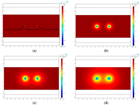
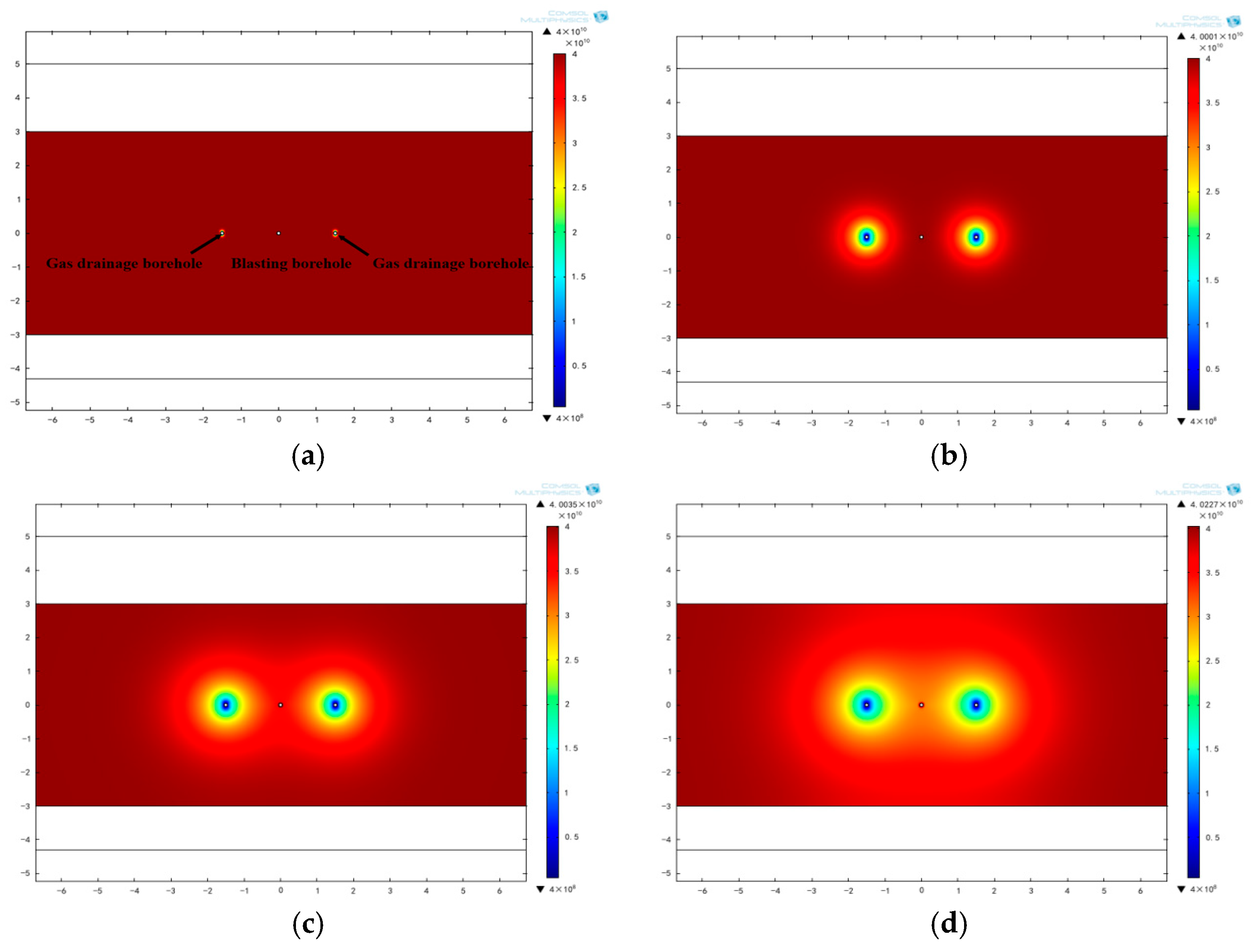
To investigate the effect of static fracturing-induced permeability enhancement on gas drainage, it is necessary to compare and analyze the gas pressure-relief range in inspection boreholes for different drainage durations. Figure 6 shows the gas distribution around the boreholes at drainage durations of 10, 30, 90, and 180 d. As shown in Figure 6, as drainage time increases, the gas content around the gas drainage boreholes on both sides of the fracturing borehole decreases continuously, and the pressure-relief influence range of gas drainage expands continuously. The amplitude of gas pressure variation around the gas drainage boreholes is significantly larger than that in the distant area. During the initial stage of gas drainage, the pressure decline rate gradually increases, and the pressure-drop coefficient is relatively high. However, as time progresses, the pressure-decline trend gradually weakens, and the rate of decrease slows, becoming more gradual.
Figure 6.
Gas pressure distribution nephogram after single-borehole static fracturing for permeability enhancement: (a) 10 d, (b) 30 d, (c) 90 d, and (d) 180 d.
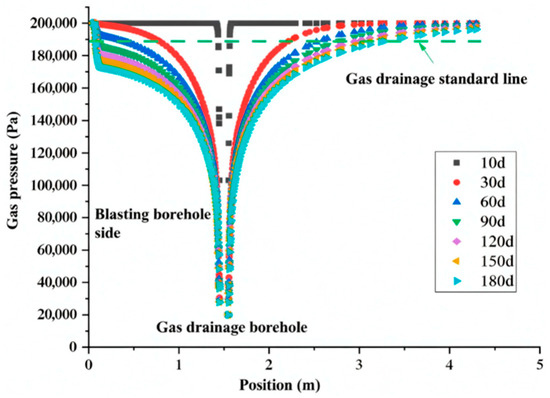
In this study, the gas drainage compliance criterion is defined as a coal seam gas drainage rate of 20%. The distance from the borehole center at which the gas pressure decreases to 0.189 MPa is taken as the effective gas pressure-relief range. Figure 7 shows the gas pressure-relief curves of the gas drainage borehole for different drainage durations.
Figure 7.
Gas pressure-relief curve of the drainage borehole after single-borehole fracturing.
As shown in Figure 7, for single-borehole static fracturing, the one-sided gas pressure-relief ranges of the drainage borehole corresponding to a gas pressure decline to 0.189 MPa at 10, 30, 60, 90, 120, 150, and 180 d were 0.07, 0.71, 1.13, 1.37, 1.54, 1.69, and 1.86 m, respectively. The pressure-relief range at 180 d increased by 64.6% relative to that at 90 d, and the pressure-relief range at 90 d increased by 92.95% relative to that at 30 d. These data indicate that after static fracturing, the gas pressure-relief range around the borehole gradually increases with drainage time; however, after 90 d, the growth rate of the pressure-relief range gradually decreases as drainage continues. The main reason that the pressure-relief range for permeability enhancement by single-borehole fracturing is not large is an insufficient number of free faces around the static fracturing borehole. Because the fracturing borehole has an insufficient number of free faces, the expansion stress cannot be effectively released and redistributed at these free faces, and a sufficient tensile stress concentration zone cannot form; consequently, fracture propagation is limited, and no additional fractures are generated.
- (2)
- Multi-borehole fracturing effect
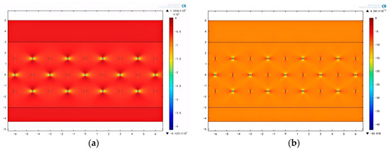
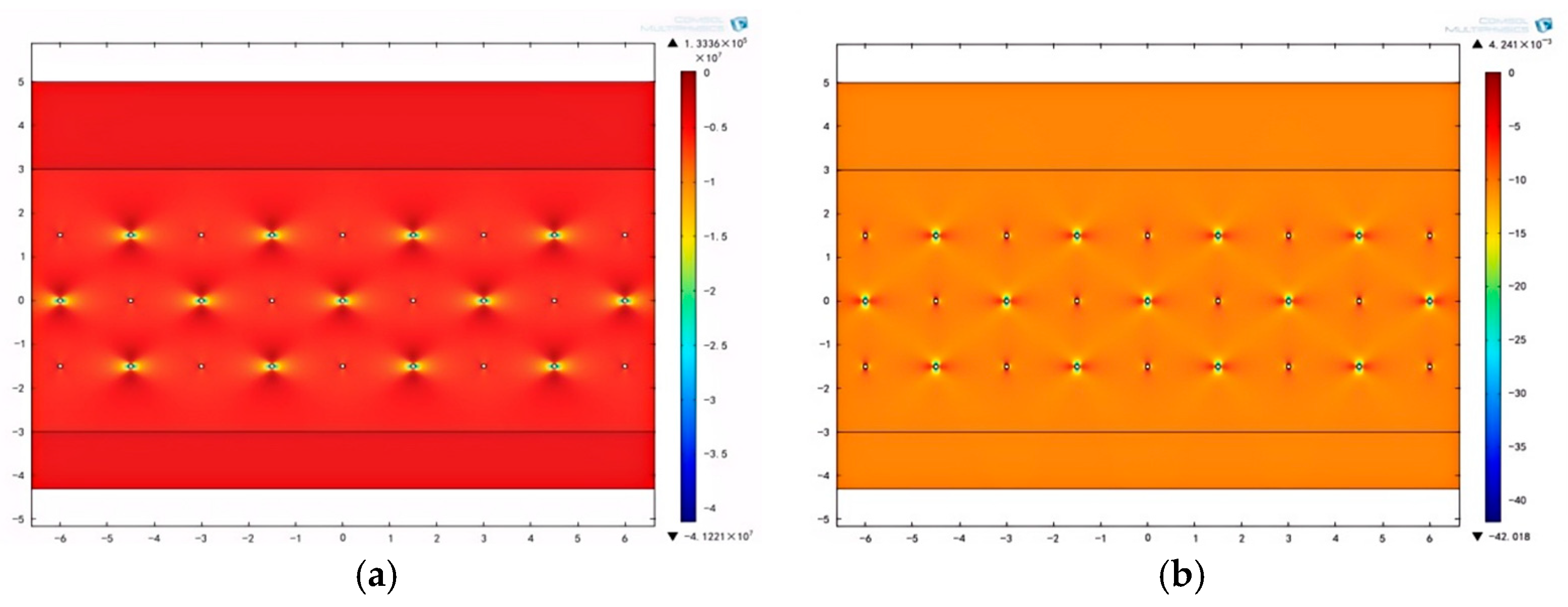
Static fracturing of coal seams is a quasi-static loading process. Free faces facilitate the release and redistribution of expansion stress, forming tensile stress concentration zones. This promotes fracture propagation and enhances permeability. To address the problem of insufficient free faces in the No. 2 coal seam, a network-pattern static fracturing scheme can be implemented, namely, combining double-borehole and guide-borehole fracturing during static fracturing, so that the expansion volume generated by static fracturing propagates to the greatest extent possible, forming a crisscross fracture network and thereby enhancing coal seam permeability. Figure 8 shows the stress distribution around boreholes after multi-borehole fracturing. It can be seen that in network-pattern fracturing, each fracturing borehole is surrounded by four drainage boreholes that act as free faces, greatly increasing the number of free faces. Consequently, the horizontal stress-relief zones above and below the fracturing borehole expand further and begin to interconnect. The stress influence range is significantly larger than that in single-borehole and double-borehole fracturing.
Figure 8.
Stress distribution around boreholes after network-pattern fracturing. (a) Horizontal stress distribution around boreholes. (b) Vertical stress distribution around boreholes.
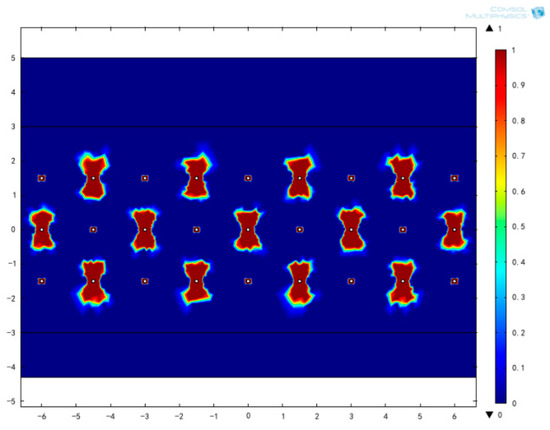
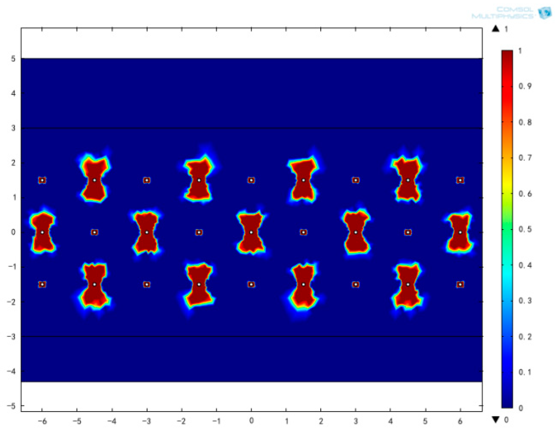
Figure 9 shows the distribution of plastic zones around boreholes after network-pattern static fracturing. The results indicate that after network-pattern static fracturing is applied to thick coal seams, the plastic failure zones around the boreholes are largely interconnected, in situ stress in most regions of the coal seam is released, and the permeability of the coal seam is further enhanced.
Figure 9.
Distribution of plastic zones around boreholes after network-pattern static fracturing.
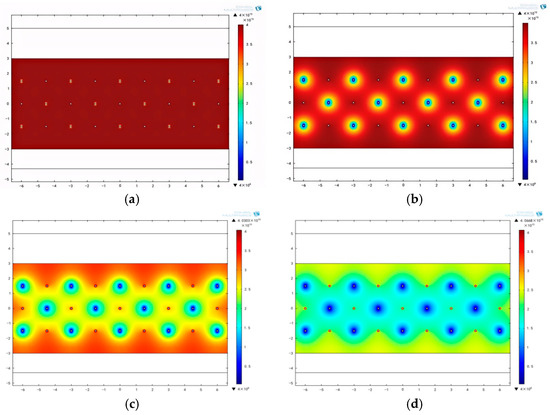
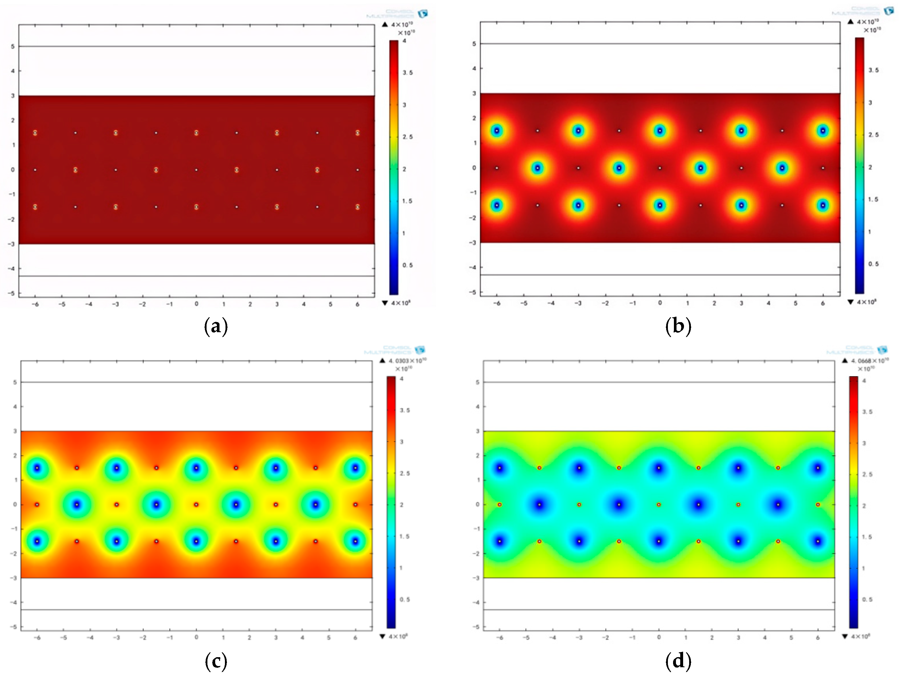
The gas distribution around boreholes after network-pattern fracturing at different drainage times is shown in Figure 10.
Figure 10.
Gas pressure distribution map after network-pattern static fracturing: (a) 10 d, (b) 30 d, (c) 90 d, and (d) 180 d.
Figure 10 shows that after network-pattern static fracturing is applied in the No. 2 coal seam, the pressure-relief effect on gas around the gas drainage boreholes is not obvious after 10d of drainage. When drainage time reaches 30d, the gas pressure around the drainage boreholes surrounding the fracturing borehole decreases significantly, and the pressure-relief range gradually expands and begins to interconnect. After 90d, the pressure-relief zones around the drainage boreholes become fully interconnected and continue to expand, forming a distribution pattern of interconnected flower-shaped pressure-relief zones. After 180d, the gas pressure in the entire coal seam is completely released.
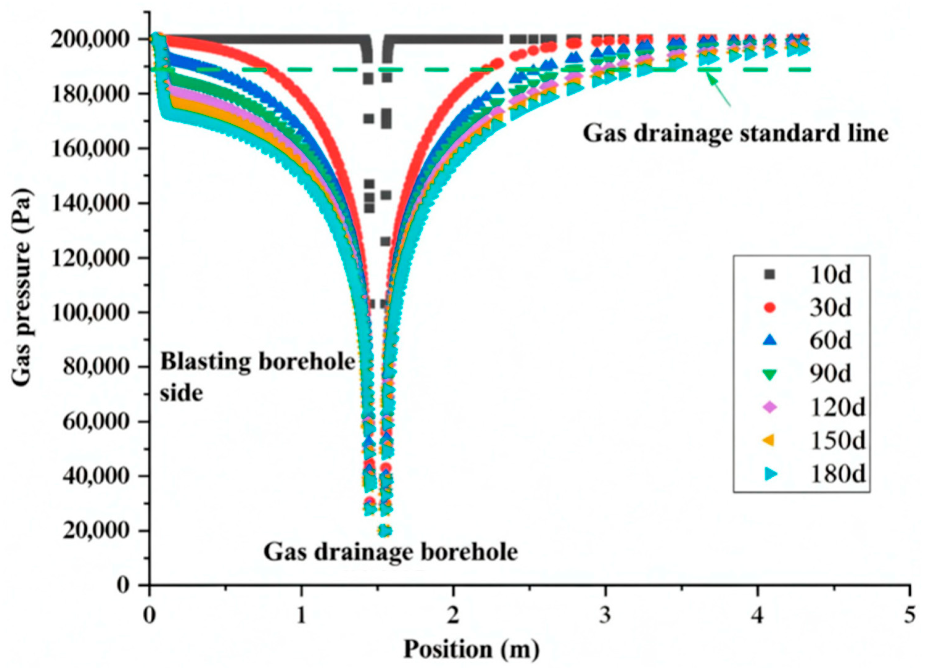
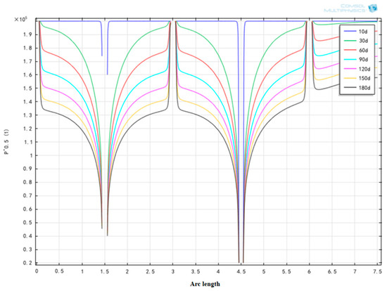
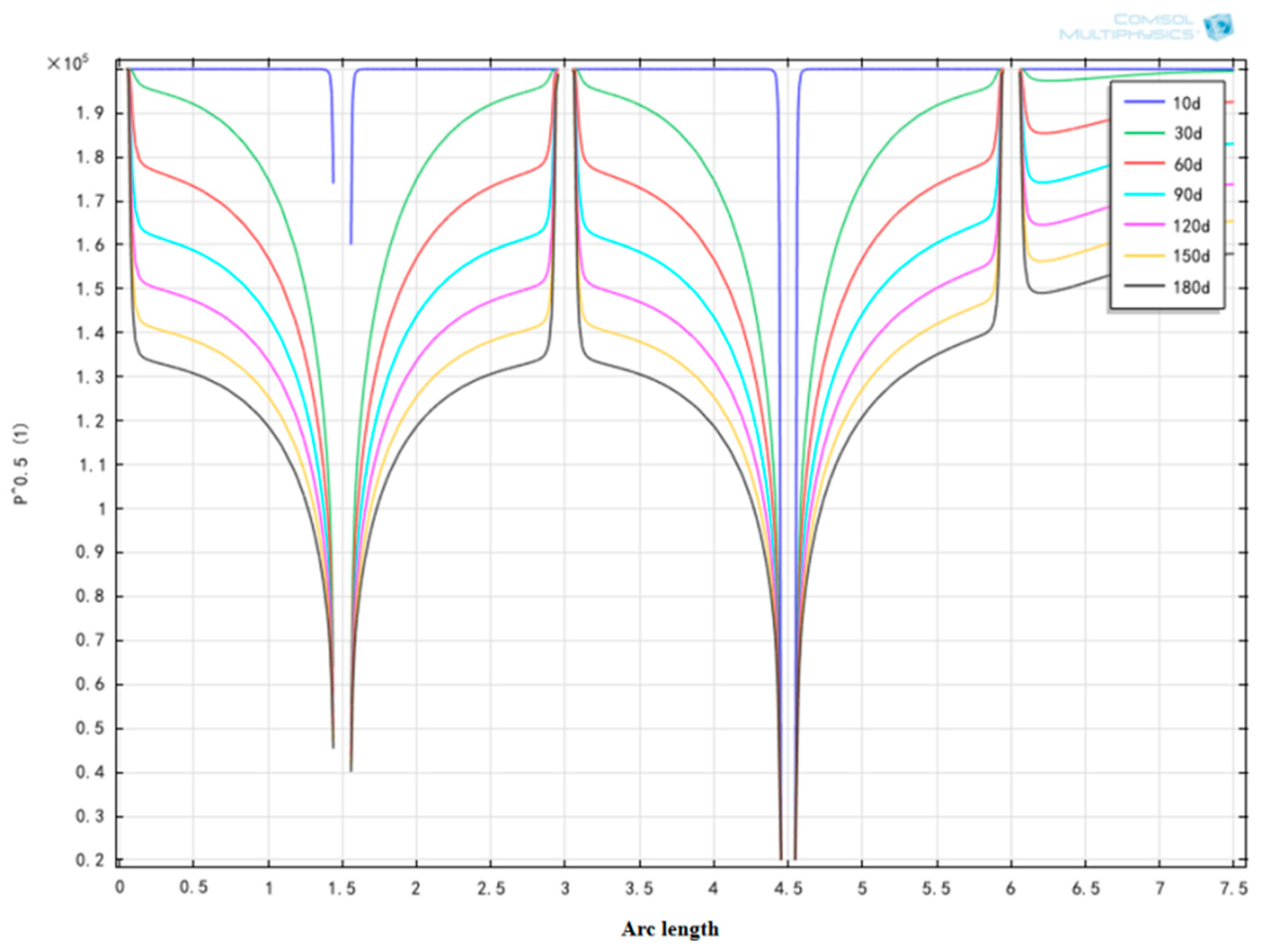
For network-pattern static fracturing, the variation in gas pressure around the drainage boreholes with distance at different drainage durations is presented in Figure 11. The results indicate that after 60 d of gas drainage, the gas pressure around the drainage boreholes decreases below 0.18 MPa, indicating that the drainage criterion is satisfied.
Figure 11.
Gas pressure variation with distance after network-pattern fracturing.
4. Field Test Verification of Fracturing
4.1. Test Design and Process Control
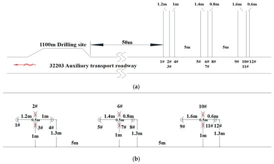
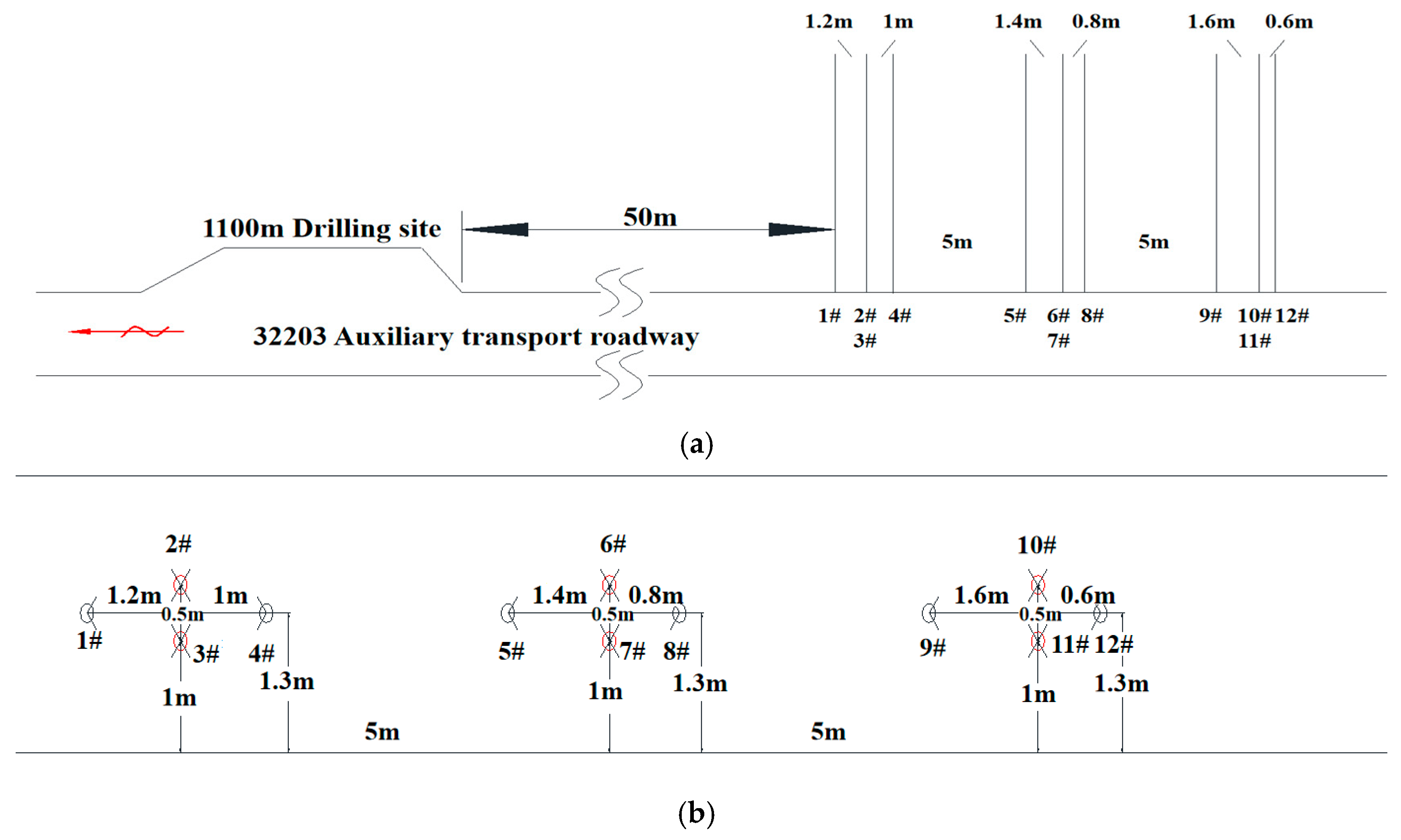
Based on the numerical simulation results and the actual layout of gas drainage boreholes at Hanzui Coal Mine, a static fracturing scheme was adopted. The site for the static fracturing field test was selected on the side of the return air roadway at the 32203 working face, 50 m from the 1100 m drilling site. A total of 12 boreholes were arranged: boreholes #2, #3, #6, #7, #10, and #11 were designated as fracturing boreholes, while boreholes #1, #4, #5, #8, #9, and #12 were designated as gas drainage inspection boreholes. The static fracturing test site and borehole layout parameters are presented in Figure 12 and Table 3.
Figure 12.
Borehole layout for static fracturing and permeability enhancement. (a) Top view of boreholes. (b) Front view of boreholes.
Table 3.
Parameters of static fracturing test boreholes in 12316 return air roadway.
4.2. Response Characteristics of Gas Drainage Parameters Before and After Permeability Enhancement and Comparison of Effects
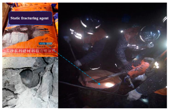
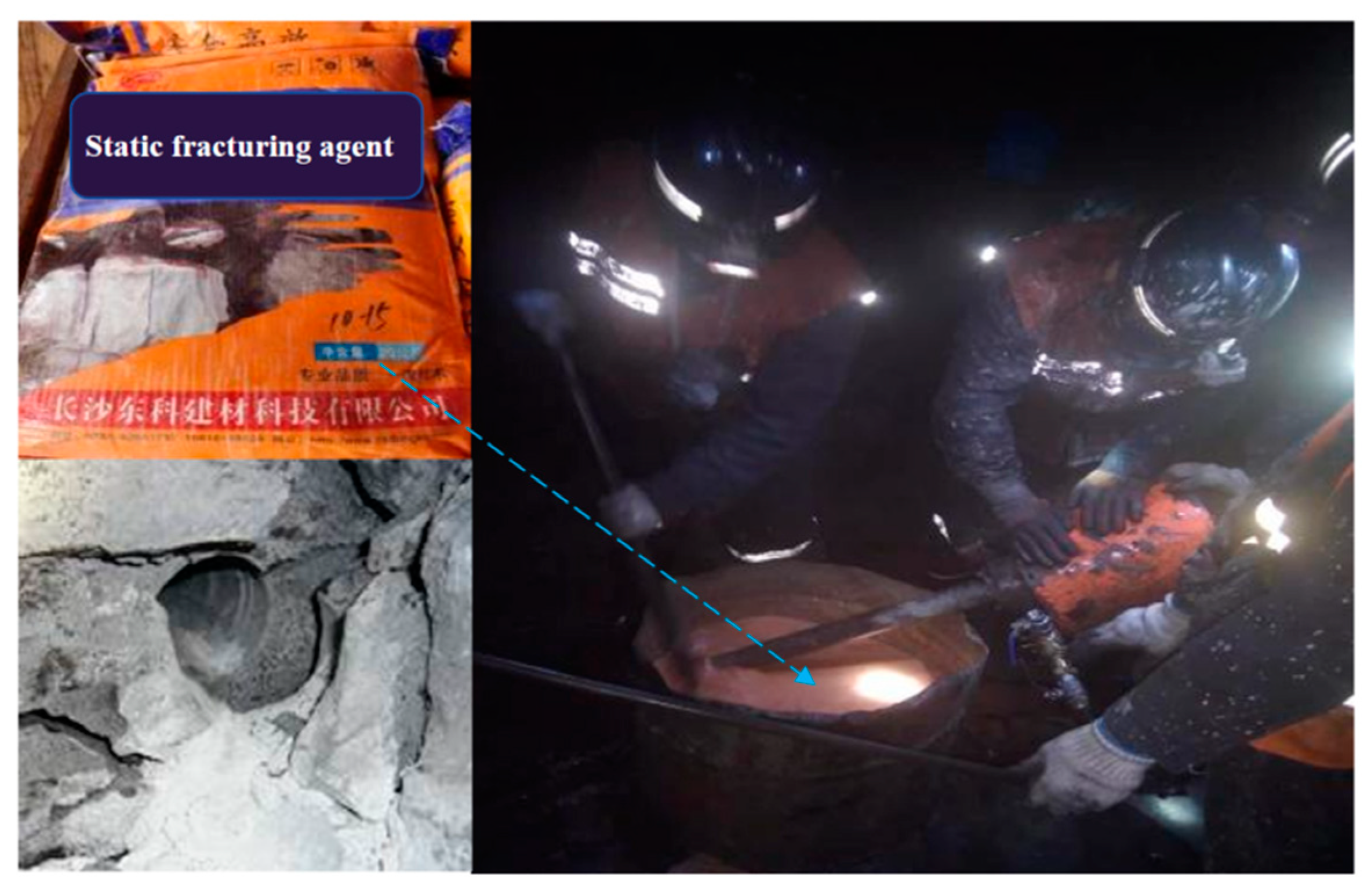
During borehole construction, the gas drainage boreholes #1, #4, #5, #8, #9, and #12 were constructed first. After continuous monitoring of the borehole flow rate and gas concentration for 7 d, static fracturing was performed in the fracturing boreholes #2, #3, #6, #7, #10, and #11. Before injecting the static fracturing agent, an exhaust pipe was installed at the bottom of each fracturing borehole to promptly discharge air from inside the borehole and to determine whether the borehole was completely filled with the fracturing agent.The field test of static fracturing is shown in Figure 13.
Figure 13.
Implementation of the static fracturing test.
- (1)
- Mixed-gas drainage flow rate
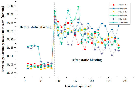
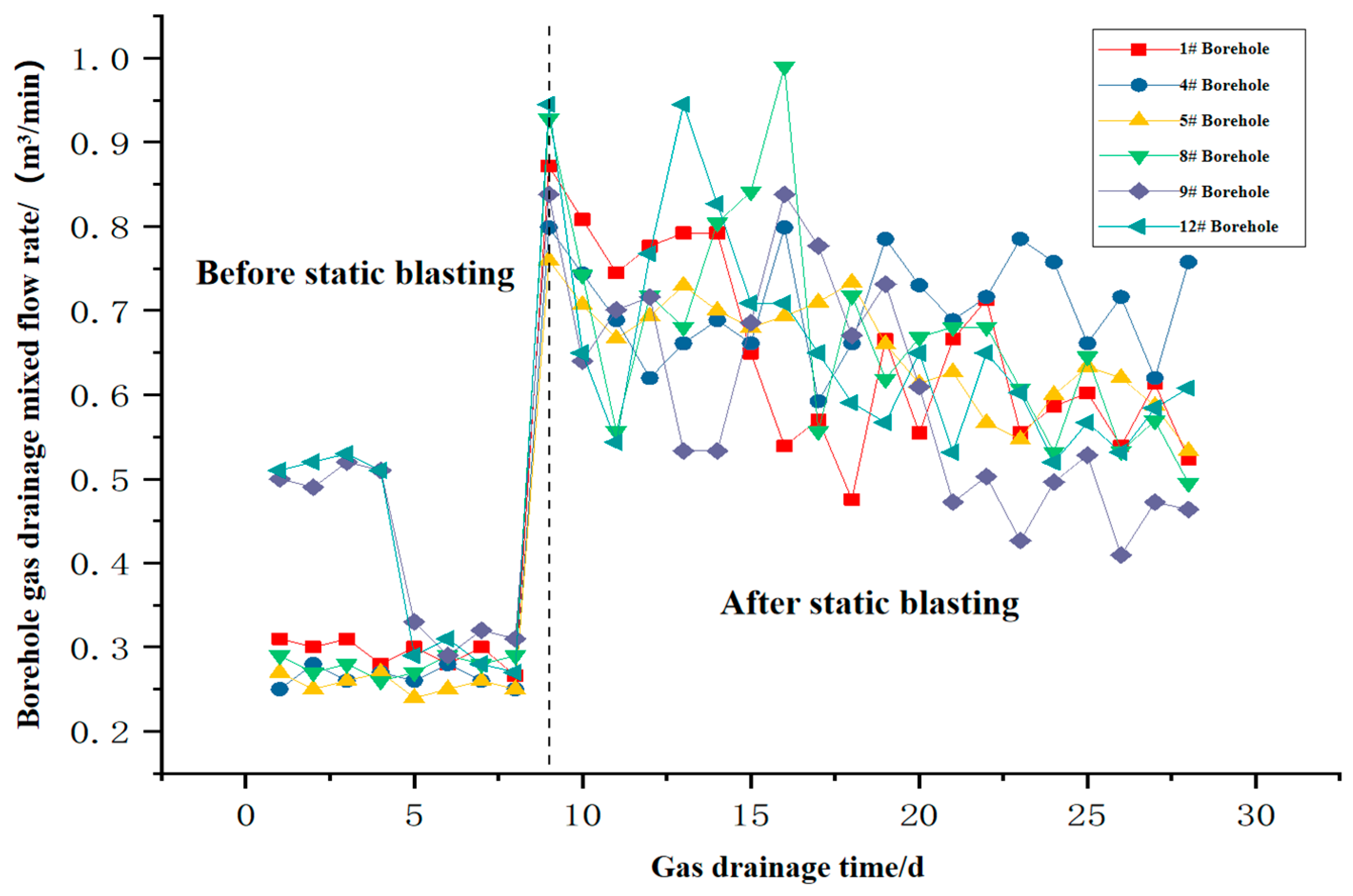
To compare the gas drainage performance of the inspection boreholes before and after static fracturing, the gas drainage negative pressure was maintained at 20 kPa, and a wet-type flowmeter was used to monitor the mixed-gas drainage flow rate of the gas drainage boreholes (#1, #4, #5, #8, #9, and #12) daily. Figure 14 shows the mixed-gas drainage flow rates for each drainage borehole over 30 d.
Figure 14.
Mixed-gas drainage flow rate before and after static fracturing.
Figure 14 shows that before static fracturing, the mixed-gas drainage flow rates for all inspection boreholes were generally low. The mixed flow rates of boreholes #1, #4, #5, and #8 remained approximately 0.3, 0.28, 0.26, and 0.28 m3/min, respectively. However, the mixed flow rates of boreholes #9 and #12 (which also served as air-leakage detection holes) were abnormal during the first 4 d, reaching a peak of 0.51 m3/min. Using a borehole sealing leakage detection device, air leakage was identified in the 8–9 m section of borehole #9 and in the 7.5–8 m section of borehole #12. Following secondary sealing, the mixed-gas drainage flow rates for boreholes #9 and #12 decreased to 0.33 and 0.29 m3/min, respectively, and subsequently returned to normal.
After static fracturing was conducted in the fracturing boreholes on day 8, the mixed-gas drainage flow rates in all inspection boreholes increased substantially, reaching 2.5–3.1 times the average mixed flow rate prior to static fracturing. Because borehole #12 was located at the shortest distance (0.6 m) from the fracturing borehole, its mixed flow rate exhibited the most pronounced increase after fracturing. On the first day after fracturing, the mixed drainage flow rate reached 0.93 m3/min and subsequently stabilized at approximately 0.68 m3/min. In contrast, borehole #9 was the farthest from the fracturing borehole (1.6 m); its mixed flow rate fluctuated noticeably after fracturing but remained significantly higher than that before fracturing, at approximately 0.55 m3/min. After static fracturing, the average mixed drainage flow rates of boreholes #1, #4, #5, and #8 remained at approximately 0.75 m3/min. With prolonged drainage time, the mixed drainage flow rates across all inspection boreholes exhibited a general gradual decline.
- (2)
- Pure-gas drainage flow rate
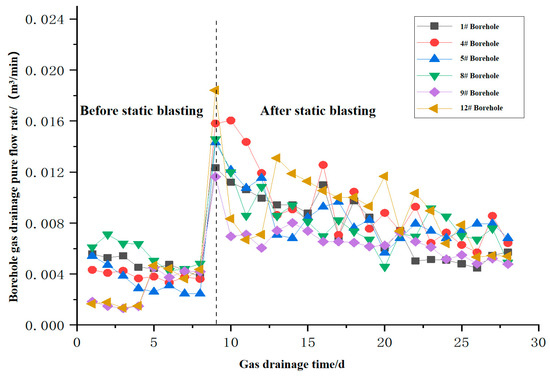
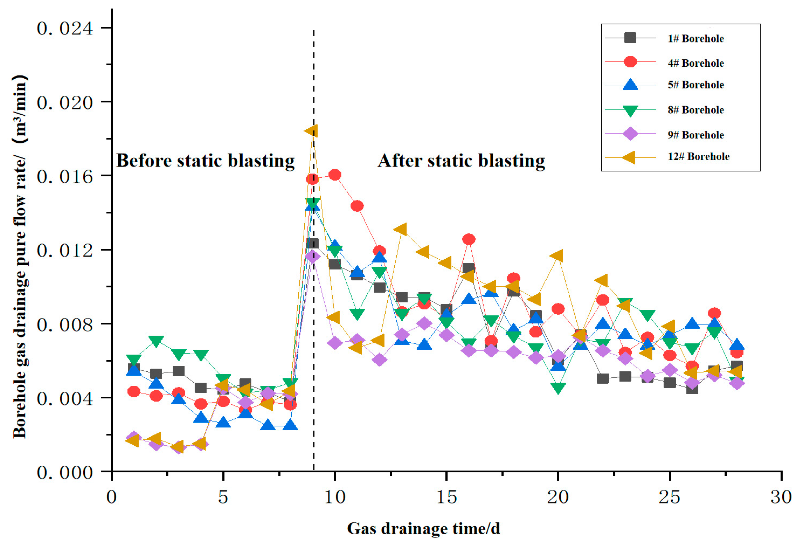
The pure-gas drainage flow rate provides a more accurate indication of gas drainage performance. To compare variations in the pure-gas drainage flow rate among the inspection boreholes before and after static fracturing, the pure-gas flow rate for each drainage borehole was calculated from the mixed-gas drainage flow rate measured by a wet-type flowmeter and the gas concentration determined by an optical gas detector, as shown in Figure 15.
Figure 15.
Pure-gas drainage flow rate of boreholes before and after static fracturing.
As shown in Figure 15, before static fracturing, the pure-gas flow rates at all inspection boreholes were generally low. The average pure-gas flow rates over the first 7 d were 0.0047, 0.0042, 0.0038, and 0.0055 m3/min for boreholes #1, #4, #5, and #8, respectively. Because air leakage existed in the inner sections of boreholes #9 and #12, gas concentrations in these boreholes were extremely low, and their pure-gas flow rates during the first 4 d of drainage were less than 0.0015 m3/min. After secondary sealing, the pure-gas flow rates of boreholes #9 and #12 increased to 0.0045 and 0.0046 m3/min, respectively, returning to normal.
After static fracturing was conducted in the fracturing boreholes on day 8, the pure-gas drainage flow rates in all inspection boreholes increased substantially, reaching 2.1–2.5 times the average pure-gas flow rate prior to static fracturing. Because borehole #12 was located at the shortest distance (0.6 m) from the fracturing borehole and had undergone secondary sealing, its pure-gas flow rate exhibited the most pronounced increase. On the first day after fracturing, the pure-gas flow rate increased to 0.018 m3/min and subsequently remained at approximately 0.01 m3/min. In contrast, borehole #9, located farthest from the fracturing borehole at 1.6 m, exhibited an increase in pure-gas flow rate to approximately twice its previous value, which then remained at approximately 0.007 m3/min. After static fracturing, the average pure-gas drainage flow rates of boreholes #1, #4, #5, and #8 remained at approximately 0.009 m3/min. As drainage time increased, the pure-gas drainage flow rates at all inspection boreholes exhibited a general gradual decline. When static fracturing is applied to the No. 2 coal seam of the 32203 working face in Hanzui Coal Mine, maintaining the horizontal distance between the gas drainage boreholes and the fracturing boreholes within 1.6 m can achieve effective pressure relief, permeability enhancement, and gas drainage. This is generally consistent with the numerical simulation results obtained from the fluid–solid coupling model for static fracturing-enhanced gas drainage.
Due to production constraints, the duration of continuous monitoring in the field test was 30 d, which was shorter than the 60 d required to meet the drainage standard predicted by the numerical simulation. The measured data over 30 d indicate that the increases in the mixed-gas flow rate and pure-gas flow rate in the observation boreholes, as well as their temporal decay trends, are generally consistent with the evolution patterns predicted by the numerical simulation during the first 30 d, indicating that the model can effectively capture the short-term permeability enhancement process following static fracturing. The simulated 60 d required to meet the drainage standard represents a theoretical prediction obtained from the fluid–solid coupling model, and its long-term accuracy still needs to be verified against longer-term field data. Future work will extend the monitoring period or perform long-term comparative tests in mines with similar conditions to further verify the reliability of the model for long-term prediction.
5. Conclusions
- ①
- The effectiveness of static fracturing for permeability enhancement is constrained by borehole layout parameters, and multi-borehole static fracturing is more effective than single-borehole static fracturing. Numerical simulation results indicate that single-borehole static fracturing is constrained by the insufficient number of free faces around the borehole, and the expansion stress generated by Ca(OH)2 cannot effectively superimpose with the reflected tensile stress, thereby limiting the range of permeability enhancement. In contrast, network-pattern multi-borehole fracturing provides multiple drainage boreholes as free faces for each fracturing borehole, thereby promoting stress superposition. The plastic failure zones around each fracturing borehole interconnect, forming an extensive fracture network, and the time required to meet the gas drainage standard is significantly reduced compared with that required for single-borehole fracturing.
- ②
- The numerical simulation results are in good agreement with the field test results, quantitatively confirming the significant permeability-enhancing effect of network-pattern static fracturing. Field test results show that after multi-borehole fracturing, the mixed-gas drainage flow rate of the inspection boreholes increased by a factor of 2.5–3.1, and the pure-gas flow rate increased by a factor of 2.1–2.5. The pure-gas flow rate of the borehole closest to the fracturing borehole increased from 0.0046 to 0.018 m3/min. The simulation-predicted pressure-relief range is consistent with the measured gas-drainage response trend, confirming the validity of the established fluid–solid coupling model.
- ③
- The horizontal spacing between gas drainage boreholes and fracturing boreholes should be maintained within the primary expansion-influence zone, with a recommended upper limit of 1.6 m. Numerical simulations and field data collectively indicate that when the horizontal spacing does not exceed 1.6 m, the fracture network induced by the fracturing boreholes can effectively encompass the gas drainage borehole area, leading to a significant reduction in gas pressure. When the spacing exceeds this threshold, the permeability enhancement effect decreases markedly. In engineering design, gas drainage boreholes should be positioned within the expansion-stress influence range of the fracturing boreholes, and a staggered layout is preferred to enhance free-face density.
- ④
- In deep mining under coupled “gas–rockburst” disasters, static fracturing serves a dual function: pressure relief and permeability enhancement, offering a potential approach for integrated control. In deep, high-stress environments, network-pattern static fracturing can not only substantially improve gas drainage efficiency but also relieve surrounding rock stress and reduce local stress concentration via the artificial fracture network. Future research should focus on developing a multi-field dynamic coupling model of the stress field, fracture field, and gas field, quantifying the synergistic contributions of fracturing parameters to pressure relief and permeability enhancement, and exploring the application of this model in coordinated active pressure relief and gas pre-drainage in rockburst-prone areas.
Author Contributions
X.M.: data curation, writing—original draft, writing—review and editing. J.G.: project administration, supervision, validation. L.X.: formal analysis, writing—original draft, writing—review and editing. X.F.: funding acquisition, project administration, supervision. H.S. and B.S.: formal analysis, methodology, validation. All authors have read and agreed to the published version of the manuscript.
Funding
This research was funded by the China Coal Huajian 2025 Science and Technology Projects.
Data Availability Statement
The data presented in this study are available on request from the corresponding author due to privacy and ethical restrictions.
Conflicts of Interest
Author Xingying Ma, Xiaogang Fan and Baoqiang Sun were employed by the company China Coal Energy Research Institute Co.Author Jiangfeng Guo, Libin Xin and Haobin Sun were employed by the company China Coal Huajin Group Hanzui Coal Industry Co. The remaining authors declare that the research was conducted in the absence of any commercial or financial relationships that could be construed as a potential conflict of interest.
References
- Wang, X.F.; Liu, W.G.; Wang, L.; Wei, Y.; Zhang, Q. Numerical simulations of enhancing permeability and gas extraction of thick coal seams through static fracturing. Coal Geol. Explor. 2023, 51, 1–12. [Google Scholar]
- National Development and Reform Commission, National Energy Administration. The 15th Five-Year Plan for the Development of the Coal Industry; Document No. Fa Gai Neng Yuan No. 979; National Development and Reform Commission: Beijing, China, 2026. (In Chinese)
- National Development and Reform Commission, National Energy Administration. Development and Utilization Plan for Coalbed Methane (Coal Mine Gas); National Development and Reform Commission: Beijing, China, 2026. (In Chinese)
- Guo, H.G.; Zhu, L.K. Research on mechanism of energy release and permeability improvement in coal strata by static blasting. China Saf. Sci. J. 2020, 30, 60–65. [Google Scholar]
- Li, C.; He, S.F.; Hou, W.T.; Ma, D. Experimental study on expansion and cracking properties of static cracking agents in different assembly states. Int. J. Min. Sci. Technol. 2022, 32, 1259–1272. [Google Scholar] [CrossRef] [Scilit]
- Zhai, C.; Wu, S.L.; Tang, Z.Q.; Zhong, C.; Xu, J.-Z. Study on seam fracturing and permeability improved technology based on static blasting. Coal Sci. Technol. 2015, 43, 54–57. [Google Scholar]
- Liu, J.; Su, M.; Zhang, L.W.; Liu, Z.-K. Coupling model of stress-damage and its application to static blasting technology. Energy Explor. Exploit. 2023, 41, 497–517. [Google Scholar] [CrossRef] [Scilit]
- Wang, J.G.; Zhang, S. Characteristics of microseismic signals and its frequency-spectrum evolvement rule during the static cracking of coal. J. China Coal Soc. 2017, 42, 1706–1713. [Google Scholar]
- Xie, X.G.; Liu, J.W.; Wang, L.; Fang, J. Testing study of expanding and cracking outburst coal seam by the static expansion agent. J. China Coal Soc. 2016, 41, 2620–2625. [Google Scholar]
- Zhang, W.; Yang, F.L.; Cao, L.C.; Chang, J.; Zhao, S.; Mao, J. Evolution law of static expansion-induced cracking and borehole parameter optimization in coal measure hard rocks. Comput. Part. Mech. 2025, 12, 3499–3520. [Google Scholar] [CrossRef] [Scilit]
- Wang, Y.; Zhang, C.; Liu, H. Synergistic roof key-strata hydraulic fracturing and in-seam static expansion to create a dual pressure-relief field for deep coal seam gas exploitation. Processes 2025, 13, 3970. [Google Scholar] [CrossRef] [Scilit]
- Bai, X.; Wang, D.; Tian, F.; Zhang, D.; Li, H.; Ren, F. Permeability model of damaged coal under triaxial stress loading-unloading. Chin. J. Rock Mech. Eng. 2021, 40, 1536–1546. [Google Scholar]
- Lin, H.F.; Long, H.; Li, S.G. Development and application of true triaxial test system for the whole process of gas adsorption-desorption, fracturing and seepage in coal. Chin. J. Rock Mech. Eng. 2022, 41, 3294–3305. [Google Scholar]
- Shang, H.B.; Jin, D.W.; Zhang, T.J.; Li, S.; Wang, Z.; Zhao, C.; Zhou, Z.; Liu, Z. Permeability evolution of broken coal under triaxial stress. J. China Coal Soc. 2019, 44, 1066–1075. [Google Scholar]
- Meng, S.P. Experimental analysis of stress-strain, permeability and acoustic emission of coal reservoir under different confining pressures. J. China Coal Soc. 2020, 45, 2544–2551. [Google Scholar]
- Palmer, I.; Mansoori, J. How permeability depends on stress and pore pressure in coalbeds: A new model. SPE Reserv. Eval. Eng. 1998, 1, 539–544. [Google Scholar] [CrossRef] [Scilit]
- Shi, J.Q.; Durucan, S. A model for changes in coalbed permeability during primary and enhanced methane recovery. SPE Reserv. Eval. Eng. 2005, 8, 291–299. [Google Scholar] [CrossRef] [Scilit]
- Zhang, Z.T.; Zhang, R.; Xie, H.; Gao, M.; Zha, E.; Jia, Z. An anisotropic coal permeability model that considers mining-induced stress evolution, microfracture propagation and gas sorption-desorption effects. J. Nat. Gas Sci. Eng. 2017, 46, 664–679. [Google Scholar] [CrossRef] [Scilit]
- Zhang, R.; Cheng, Y.P.; Zhou, H.X.; Yuan, L.; Li, W.; Liu, Q.; Jin, K.; Tu, Q. New insights into the permeability-increasing area of overlying coal seams disturbed by the mining of coal. J. Nat. Gas Sci. Eng. 2018, 49, 352–364. [Google Scholar] [CrossRef] [Scilit]
- Gao, X.; Gao, F.; Zhang, N.; Cheng, H.; Xing, Y. Numerical simulation of stress and permeability evolution in damaged coal. Int. J. Non-Linear Mech. 2025, 168, 104953. [Google Scholar] [CrossRef] [Scilit]
- Wang, C.Z.; Zhou, B.; Li, S.G.; Lin, H.; Shuang, H.; Zhang, D.; Peng, S.; Cheng, L.; Yang, H. Dominant governing mechanisms of deformation-seepage and dynamic evolution model of permeability in gas-containing coal under coupled stress-pore pressure. Fuel 2026, 404, 136408. [Google Scholar] [CrossRef] [Scilit]
- Wang, X.Y.; Zhou, H.W.; Xue, D.J.; Zhang, L.; Li, K. Synergistic and participation mechanisms of effective stress and temperature on coal mechanical behavior and permeability characteristics. Energy Fuels 2025, 39, 7223–7234. [Google Scholar] [CrossRef] [Scilit]
- Wang, X.F.; Hao, F.; Xu, H.; Zhu, C.; Jiang, T.; Jiang, Y. Static expansion fracturing mechanism for enhancing gas permeability in low permeability coal seams. Sci. Rep. 2024, 14, 25046. [Google Scholar] [CrossRef] [Scilit] [PubMed]
- Wang, Y.T.; Zhao, X.; Wang, P.F.; Chen, Y. Gas Evolution Principle during Gas Drainage from a Drill Hole along the Coal Seam and Reasonable Borehole Layout Spacing. ACS Omega 2023, 8, 44338–44349. [Google Scholar] [CrossRef] [Scilit] [PubMed]
- Duan, M.K.; Lu, M.J.; Yang, K.; Ban, R.; Hu, X.; Jiang, C.; Lyu, X. Gas drainage and optimal arrangement of boreholes based on permeability anisotropy. Geomat. Nat. Hazards Risk 2023, 14, 2272573. [Google Scholar] [CrossRef] [Scilit]
- Zhao, K.K.; Liu, C.X.; Hua, Y.; Feng, Y.; Sun, X.; Zhang, C. Permeability enhancement simulation of hydraulic fracturing in underlying coal seams in goaf. Geomech. Geophys. Geo-Energy Geo-Resour. 2025, 11, 86. [Google Scholar] [CrossRef] [Scilit]
- Hou, B.Q.; Li, Z.W.; Yang, W.; Gao, Y.; Wang, Y.; Hao, Z. Impact of hydraulic fracturing combined with CO2 gas injection displacement on coalbed methane extraction. Int. J. Coal Geol. 2026, 202, 106491. [Google Scholar] [CrossRef] [Scilit]
- Shi, B.; Cao, Y.X.; Tian, L.; Zhang, J.S.; Liu, S.M. CO2 Gas Fracturing in High Dip Angled Coal Seams for Improved Gas Drainage Efficiency at Hashatu Coal Mine. Energy Fuels 2022, 36, 2763–2774. [Google Scholar] [CrossRef] [Scilit]
- Miroshnichenko, D.V. Influence of Oxidation on the Packing Density of Coal. Coke Chem. 2014, 57, 183–191. [Google Scholar] [CrossRef] [Scilit]

Disclaimer/Publisher’s Note: The statements, opinions and data contained in all publications are solely those of the individual author(s) and contributor(s) and not of MDPI and/or the editor(s). MDPI and/or the editor(s) disclaim responsibility for any injury to people or property resulting from any ideas, methods, instructions or products referred to in the content. |
© 2026 by the authors. Licensee MDPI, Basel, Switzerland. This article is an open access article distributed under the terms and conditions of the Creative Commons Attribution (CC BY) license.