


Abstract
The use of steam-based thermal recovery techniques in heavy oil exploitation faces critical limitations in deep formations, aquifer-bearing reservoirs, and formations with high clay content. This has motivated increasing research interest in the use of non-condensable gases (NCGs; mainly CO2, N2, and flue gas) in this context. This review systematically synthesizes the results of experiments, numerical simulations, and field implementations related to NCG-enhanced heavy oil recovery, with special emphasis on clarifying ambiguous recovery mechanisms, comparing the performance under different injection modes, and describing key controlling parameters and existing technical bottlenecks. CO2 mainly contributes to oil mobilization by reducing oil viscosity and causing oil swelling after dissolution, while N2 primarily maintains reservoir pressure. Flue gas combines the advantages of both of these gases. Of the different injection patterns, cyclic huff and puff has received the most research attention, whereas studies on steam-assisted gravity drainage (SAGD) with NCGs remain insufficient. When co-injected with steam, NCGs can elevate reservoir pressure and mitigate steam heat loss; nevertheless, multiple potential mechanisms, including interfacial tension reduction, water wettability alteration, and solution gas drive, have not been quantitatively characterized. Our review shows that most existing laboratory and simulation investigations have adopted single-factor analysis, and multi-factor coupling evaluation considering reservoir fluid properties is urgently required. N2 foam flooding effectively suppresses detrimental gas channeling and steam override. Field cases demonstrate that combined steam flue gas injection can achieve up to 79% original oil in place (OOIP) recovery, yet gas channeling and asphaltene precipitation still restrain field performance. This work further summarizes field-scale failure triggers, identifies critical research gaps, and provides targeted suggestions for future laboratory optimization and pilot scheme design for NCG applications in heavy oil reservoirs.
1. Introduction
Due to the decline in conventional oil reserves and the increase in global demand for fossil fuels, there is a growing interest in exploring unconventional resources such as heavy oil and bitumen [1,2,3,4,5]. Recent data indicate that unconventional oil reserves, including heavy oil, extra-heavy oil, and bitumen, surpass six trillion barrels worldwide, nearly three times the volume of conventional oil and gas reserves [6,7,8]. The countries leading the charge in heavy oil exploration and production are, in ascending order, the United States, Canada, Venezuela, and China [9,10].
Thermal techniques—predominantly steam injection in cyclic steam stimulation (CSS), steam flooding (SF), steam-assisted gravity drainage (SAGD), and in situ combustion—are commonly employed to recover heavy oil/bitumen [11,12,13]. The enhanced recovery efficiency of these thermal methods is often linked to specific reservoir conditions, particularly in formations less than 200 m below sea level or the surface. Conversely, deeper formations tend to exhibit lower recovery efficiency [14]. Challenges such as bottom aquifers, overlying water, and high clay mineral content, especially when the clay content exceeds 10%, can impede the applicability of these methods [15]. In such adverse conditions, hydrocarbon solvents and non-condensable gases including carbon dioxide (CO2), nitrogen (N2), methane (CH4), and flue gases—either alone or in conjunction with steam—are promising alternatives to thermal methods [15,16].
Despite the potential economic benefits, conventional development methods have several limitations, such as significant steam loss due to significant channeling, limited heat effectiveness, and substantial greenhouse gas emissions [17,18,19]. The efficacy of pure steam injection is notably low, particularly for oil sand or heavy oil reservoirs; incorporating non-condensable gases (NCGs) like flue gas into the steam injection process has shown potential to enhance both the economics and production rates of conventional steam recovery methods [20].
Compared with N2, CO2 is more commonly applied in experimental, simulation, and field studies of heavy oil recovery because of its higher solubility in heavy oil. NCGs can be applied in all modes of production, including huff and puff (which is similar to cyclic steam stimulation (CSS)), continuous injection (which resembles steam flooding (SF)), and non-condensable gases–steam-assisted gravity drainage (SAGD). Huff and puff is the leading mode of production for analysis and applications, while there have been few studies on SAGD production.
In all modes of production, the main mechanisms of CO2 recovery are oil swelling, reduction in viscosity due to the solubility of CO2 in heavy oil through the diffusion process, and foamy oil formation [21,22,23,24]. However, there are other driving mechanisms that are rarely mentioned in the literature, such as decreasing interfacial tension, enhancing water wettability, three-phase relative permeability, the solubility of CO2 in water, light-to-medium hydrocarbon extraction, solution gas drive phenomena, the use of CO2 as a water blockage agent, and reactions associated with concurrent induction movements with the rock that might stimulate near-wellbore permeability [25,26,27,28]. In SAGD, gravitational separation due to density differences also contributes to oil enhancement. N2 gas drives heavy oil recovery through reservoir pressure build-up, differentials due to gravity (density differences), and the expanding volume of gas, with limited oil viscosity reduction and swelling compared to CO2. In the co-injection of steam and non-condensable gases, other recovery mechanisms include reservoir pressure maintenance and steam heat insulation caused by heat loss in overburdened rocks [29,30]. Flue gas–steam co-injection combines the advantages of the driving mechanisms of all the phases [31].
Liquid CO2 is suitable for use in reservoirs with a temperature below the critical temperature of CO2 (31.1 °C), while supersaturated CO2 is suitable when the reservoir temperature is above the critical temperature of CO2. Higher oil recovery factors are obtained when supersaturated CO2 is used [32,33]. The mechanized factors that control the CO2 huff and puff mode are injection pressure, injection cycles, soaking time, and injection rate. Recovery factor has been shown to increase with injection pressure until minimum miscibility pressure (MMP) is reached, meaning that the oil factor does not significantly increase [34,35,36,37]. An increasing pressure depletion rate has also been shown to increase the recovery performance within a given domain, which emphasizes the need for sensitivity analysis [36,38,39]. The recovery factor has also been shown to increase with the number of injection cycles; however, the optimal number of cycles must be determined, since the final cycles are associated with a minor additional recovery factor that is dependent on the company’s economic factors [35,36,37,40]. Soaking time is an important parameter that further enhances oil displacement as it increases [36,41]. The optimal soaking time can be estimated by taking the highest rate obtained after dividing cumulative oil produced by the soaking time. The orthogonal method has been used to investigate the key controlling factors in a continuous CO2 injection experiment, and temperature was found to play a key role. Our review found that there are very few experimental, simulation, and field studies exploring the parametrization of pure N2 injection, but steam and N2 co-injection are common.
Steam and non-condensable gas injection production schemes can be alternating or co-injection/simultaneous, depending on the results of performance analysis [42]. The injection mole fraction and injection rates of the two parts (steam and non-condensable gas) affect the recovery factor under variable temperatures, and it has been shown that the recovery factor first increases as the ratio of gas–liquid (steam) increases due to increasing swept area efficiency and steam heat insulation. However, a carefully estimated optimal ratio is needed, since the trend starts to decline as the ratio continues to increase after a certain point [30,40,43].
Flue gas, which is composed of approximately 80 to 85% nitrogen (N2) and 10 to 15% carbon dioxide (CO2) and other impurities, has been shown to improve oil recovery factor performance in comparison with steam alone or steam with nitrogen co-injection [44,45]. Flue gases can be directly used in the heavy oil field by simply capturing them from steam boiler generators [46]. After the utilization of flue gas, oil recovery increases as the ratio of flue gas to steam increases; however, it must be emphasized that a sensitivity analysis must be carried out in order to optimize the ratio, as stated in [47].
The combination of a chemical agent, water, and N2, which is called foam injection, has been shown to increase the recovery factor by reducing the overriding and channeling effects of gas or steam in several studies [48,49,50,51,52]. Foam injection studies involve the estimation of a new parameter: the resistance factor. This is controlled by the gas–liquid ratio, permeability, the injection pattern of fluids, and the contacted fluid (water or oil). An increase in the value of the resistance factor leads to increased oil recovery factors [52]. Therefore, more studies of the parameters affecting the resistance factor should be conducted.
CO2 field projects have been successful at the Lick Creek field in the United States of America (USA), Bati Raman in Turkey, Bohai in China, and Oropouche in Trinidad, with the noted mechanical problems of gas channeling diminishing the recovery factor at the Oropouche field [53]. Flue gas injection with steam has also shown significant incremental positive oil recovery enhancement in the Kansas Lacyne–Cadmus field in the USA, and Bohai and Shengli in China [31].
Numerous previous reviews have separately described individual non-condensable gas (NCG)-enhanced heavy oil recovery technologies, such as CO2 huff and puff, N2-assisted steam processes, or flue gas injection. Most existing reviews have mainly focused on a single gas agent or a single injection mode. Comprehensive comparative summaries covering CO2, N2, and flue gas together across huff and puff, continuous flooding, and SAGD modes are still limited. Moreover, previous summaries rarely systematically identify ambiguous and incompletely quantified driving mechanisms (e.g., interfacial tension reduction, wettability alteration, solution gas drive), and few of them distinguish parameter sensitivities for single gas injection versus gas–steam co-injection scenarios. In addition, the gaps between laboratory simulation single-factor analysis and multi-factor coupling evaluation have not been sufficiently emphasized, and field implementation bottlenecks, including gas channeling, asphaltene precipitation, and foam-related problems, require further consolidated analysis.
Therefore, this review aims to fill the abovementioned research gaps. The primary objectives are (1) to systematically compare recovery mechanisms, parametric characteristics, and application performance of three typical non-condensable gases (CO2, N2, flue gas) under huff and puff, continuous flooding, and SAGD production modes based on experimental, simulation, and field case data; (2) to verify well-known and under-explored driving mechanisms that lack quantitative support in the existing literature; (3) to summarize key controlling parameters for pure gas injection and gas–steam co-injection, and highlight the limitation of conventional single-factor analysis and the necessity of multi-factor coupling research; (4) to summarize N2 foam mitigation for gas channeling problems, and consolidate field application experiences and typical failure triggers of NCG projects; and (5) to propose targeted recommendations for future laboratory investigations and field pilot implementations for NCG-based heavy oil development.
2. Huff and Puff Injection Mode and Its Recovery Mechanics
The huff and puff process consists of injection, soaking, and production stages. In the first stage, CO2 passes over the non-movable oil and forces part of the movable oil and free water into other locations of the formation, causing an increase in the relative permeability of heavy oil near the wellbore. The portion of oil that is free to move near the wellbore stays in position when in contact with the injected CO2. During the injection process, the diffusion process is commonly assumed to be negligible due to the smaller diffusion coefficient of CO2 in heavy oil; additionally, the injection time is short, and the injection rate is high. The reservoir pressure continues to increase until the end of the injection process. During the soaking stage, diffusion and the key recovery-driving mechanisms (i.e., reduction in viscosity and swelling) occur when light components from the heavy oil are extracted by CO2 through the action of mass transfer. The last stage is production, where non-dissolved CO2 gas is transported into the production well together with expanded oil due to CO2 diffusion. Finally, heavy oil is produced at a further location in the reservoir because of the forces generated by pressure drops. Then, the remaining part of the swelled oil is taken to the production well by the water, which is still movable. The process is shown in Figure 1.
Figure 1.
CO2 recovery mechanism through the huff and puff process: (a) oil drops are flushed to a further location in the reservoir by CO2; (b) light/medium components are extracted by CO2; (c) CO2 dissolves into heavy oil; (d) oil drops connect together due to oil swelling; (e) the fluid flow direction; (f) residual oil due to change in wettability; (g) oil drops generated from swelled oil in the soaking stage; and (h) oil drops in the water phase are driven from the further location [33].
Depending on the specific pressure and temperature of the reservoir, as well as the composition of composite oil in the reservoir, supercritical CO2 frequently achieves miscibility with oil. This means that the crude oil and CO2 completely blend together, forming a single liquid phase. This interaction causes the oil volume to expand, reduces its viscosity, and lessens surface tension effects, ultimately enhancing the recovery of oil from the reservoir. Even if complete miscibility is not achieved, CO2 injection will upgrade the recovery factor, especially in heavy oil or low-pressure oil reservoirs. Even though the injected gas is not completely miscible, it can be partially dissolved in oil and thereby stimulate a certain level of swelling and viscosity reduction. It has been observed that a viscosity reduction of 10 magnitudes can still be achieved, even under poor-quality reservoir conditions [54].
The immiscible displacement process is not commonly utilized due to its unfavorable economics. This is primarily because it demands substantial amounts of CO2 and the construction of new wells, with additional oil production occurring at a slow rate. Additionally, immiscible projects are usually implemented across the entire reservoir, restricting opportunities for smaller-scale deployment. Most hydrocarbon reservoirs are found at a depth where the critical temperature of CO2 (31.1 °C) is already exceeded. In reservoirs at less than this temperature, liquid-state storage can be beneficial [55].
The CO2 process relies heavily on oil swelling, reduction in oil viscosity, and foamy oil mechanisms [21,22]. However, these mechanisms alone may not sufficiently contribute to the recovery of oil in the huff and puff process [56]. Additional factors that are crucial for improving recovery include decreasing interfacial tension, enhancing water wettability, the relative permeabilities of all phases, the solubility of CO2 in water, distillation and extraction of light to medium hydrocarbons, the gas used in solution, the action of CO2 as a water blockage agent, and the countercurrent reactions that induce and stimulate permeability near the wellbore area [25,26,28,57]. These factors, among others, play significant roles in optimizing heavy oil recovery processes when employing CO2 injection techniques.
2.1. Heavy Oil Viscosity Reduction as a Driving Mechanism
Previous research has suggested that viscosity reduction has a more pronounced effect on heavy oil with a lower API gravity [58,59]. When CO2 is introduced into heavy oil under appropriate reservoir conditions, a significant reduction in the heavy oil’s viscosity will occur. The primary causes of viscosity reduction include the removal of coarse-grained matter, dilution of the viscous heavy components, and demulsification action between heavy oil and CO2 [60].
Less viscous oil causes the curve of the water fraction flow to shift to the right; this means that, for the same water saturation level, there is a decrease in the flow fraction of water in the reservoir compared to before CO2 injection. This increase in oil mobility and connectivity results in a higher relative flow of oil rate [61]. The pressure, temperature, and the solubility of CO2 are parameters that have been shown to impact the reduction rate of heavy oil viscosity [62]. Figure 2 shows the rate of reduction in viscosity and CO2 solubility in heavy oil at a variety of pressures and temperatures. It shows that heavy oil viscosity is significantly reduced as temperature increases. For instance, at 60 °C and 93 °C, there are 86.8% and 97.3% decreases in heavy oil viscosity, respectively.
Figure 2.
Viscosity reduction ratio and solubility as a function of pressure under variable constant temperatures [33].
When the temperature is below the critical value during injection, reduction in viscosity might occur at smaller pressures because liquids have a smaller mass transfer coefficient compared to gases. Consequently, pressure cannot be said to significantly impact solubility. Under constant pressure, the rate of reduction in viscosity decreased as temperature increased due to the decreased solubility of CO2 in heavy oil at higher temperatures; at higher temperatures, viscosity is usually lower, leading to a reduced potential for further viscosity reduction. CO2 injection can reduce viscosity more effectively in heavy oils with a higher initial viscosity [62]. Finally, it can be seen that the solubility increase of CO2 in heavy oil causes a subsequent significant reduction in oil viscosity during CO2 injection.
2.2. Oil Swelling as a Driving Mechanism
Oil swelling occurs once CO2 comes into contact with the heavy oil because dissolution occurs, which causes the oil volume to expand [63,64]. Oil swelling has an important effect on recovery improvement due to several factors. Oil swelling benefits movable oil, and the generated drainage forces displace water from pore spaces due to dissolved CO2; therefore, swelling increases the oil saturation together with the fraction flow of oil in the production phase [57,65].
The extent of oil swelling is influenced by temperature, pressure, and oil composition [66]. At constant pressure and temperature, there is a direct proportionality between the swelling factor of oil and solubility. When the temperature exceeds the critical value, the extent of oil swelling is linearly correlated with pressure at different temperatures. The CO2 phase also significantly impacts the swelling behavior of oil. In regions of low pressure, CO2 is in the gas phase, and the swelling effect increases with pressure; however, as the pressure increases and the gas transitions into a liquid state, the influence of pressure on swelling becomes negligible. In lower-pressure regions, an increase in temperature leads to a decrease in CO2 solubility and hence a reduced impact of oil swelling. Conversely, in regions of higher pressure, the swelling factor is promoted at lower temperatures due to an increased CO2 solubility caused by phase change. Compositionally, lighter oil can form more swelled oil because of its higher CO2 dissolving capacity. Figure 3 shows the variation in the oil swelling factor as a function of pressure under different constant temperatures.
Figure 3.
Oil swelling factor as a function of pressure under variable constant temperatures [67].
Supercritical CO2 dissolves very easily in hydrocarbon fluids and significantly increases the volume of crude oil. The swelling behavior is influenced by composition, pressure, and temperature. Under certain working conditions, once 123.8 m3 of CO2 is dissolved in 1 m3 of oil, oil volume increases by almost 35% [68]. At a pressure of 4–6 MPa and a temperature of 20–25 °C, 50–100 m3 of CO2 will dissolve in 1 m3 of oil, yielding a reduction in oil viscosity of about 90% and an increase in oil volume of 10–20% [69]. Figure 4 shows the variation in solubility of CO2 in the Liaohe oil field from the Guantao formation, which is directly proportional to the applied pressure and inversely proportional to temperature. A 15% increase in oil volume was measured under 10 MPa at a temperature of 200 °C, where the value of solubility in the graph is 34 m3/m3.
Figure 4.
Carbon dioxide solubility in the Guantao formation oil sample [70].
2.3. Carbon Dioxide (CO2) Diffusion into Heavy Oil Drive
The diffusion coefficient is another crucial parameter influencing the characteristics of CO2 and heavy oil interactions. It signifies the flux rate at which CO2 dissolves into heavy oil [70,71,72,73]. Previous research suggests that, during the vapor extraction process in heavy oil production, production primarily occurs in the zone of transition. This zone is responsible for the formation of saturation between the solvent (CO2) and heavy oil, whose size is a function of the solvent molecular diffusion rate [74]. CO2 dissolves gradually into the heavy oil reservoir—specifically, during the soaking phase—through the transfer of mass (molecular diffusion). This phenomenon causes a decrease in viscosity values and expansion of the oil, thereby enhancing heavy oil production.
The diffusion coefficient is influenced by pressure, temperature, and composition. The diffusion coefficient is more strongly affected by pressure at higher temperatures than at lower temperatures due to two main reasons. First, at higher temperatures, oil molecules exert lower surface tension, facilitating a higher rate of mass transfer for CO2 molecules into heavy oil. Second, a rise in temperatures results in a lower viscosity of heavy oil, which makes it easier for CO2 molecules to pass through the interface. However, at extremely high levels of pressure, the system’s density and viscosity also increase, leading to a gradual decrease in the diffusion coefficient [75,76,77].
At a constant temperature, the diffusion coefficient increases with rising pressure, particularly in the lower pressure range. This is primarily because higher pressures provide a stronger force driving the transfer of CO2 into heavy oil. The collective influence of pressure and temperature indicates that the CO2 diffusion coefficient rises with increases in both temperature and pressure. Consequently, it can be inferred that, as the viscosity of heavy oil increases, the diffusion coefficient of CO2 in heavy oil decreases. The solubility of CO2 is known to rise with increasing pressure and decline with increasing temperature. However, there is no notable correlation with the CO2 diffusion coefficient. These relationships are depicted in Figure 5.
Figure 5.
Diffusion coefficient and solubility parameters as a function of pressure and temperature [33].
2.4. Analysis of CO2 Huff and Puff Parameterization Employing Experiments and Simulations
The experimental cases summarized in this review cover the diverse simulated geological conditions of heavy oil reservoirs. The experimental reservoir temperature ranges from 21 °C to 200 °C, covering both subcritical and supercritical CO2 temperatures. Experimental simulation pressures vary broadly, from several MPa up to 25 MPa, including pressures below and above the CO2 minimum miscibility pressure (MMP). The tested heavy oil viscosities span hundreds to over 120,000 mPa·s, representing typical offshore/onshore heavy oil and extra heavy oil samples from China (Bohai, Xinjiang, Shengli, Liaohe oil fields), Canada, Turkey, and Brazil. The core and sand pack models used in these experiments have absolute permeability ranging from hundreds of millidarcies to approximately 2D, with porosity values mainly distributed between 20 and 34.4%. Some experiments also consider adverse geological factors such as bottom water reservoirs, formations with high clay content, and reservoir heterogeneity, which correspond to the actual geological constraints of heavy oil fields.
A previous experimental and numerical study on CO2 huff and puff showed that, once the injection pressure increases, it approaches the MMP, which leads to higher recovery. Three pressures were used in this experiment—1500, 2000, and 2500 psi—of which 2500 psi gives the best results [78]. As the pore volume is injected with more CO2, the recovery factor increases. Recovery efficiency was seen to decrease with the rate of injection.
The rate of pressure depletion plays a crucial role in determining heavy oil production performance [36,39]. When considering variable pressure depletion rates (0.5, 4, and 16 kPa/min) alongside a constant injection pressure of 5000 kPa, the highest heavy oil recovery factor was achieved at a pressure depletion rate of 4 kPa/min. This is because of (a) a markedly reduced 0.5 kPa/min rate of pressure decline, which is the lowest rate, meaning the foamy oil behavior exhibited weaker characteristics compared to those observed under a higher-pressure depletion rate; and (b) at a significantly elevated pressure depletion rate of 16 kPa/min, although the foamy oil behavior was robust, the gas bubbles tended to be larger. These larger bubbles migrated towards the vicinity of the production port, leading to pore-throat blockage and subsequently reducing the oil recovery factor.
Experiments were performed with CO2 huff and puff to assess the impact of pressure depletion rates (16, 4, and kPa/min), soaking times (20, 10, and 5 h), and, finally, the number of injection cycles. The following results were obtained:
- The heavy oil recovery factor declined when the rate of pressure depletion exceeded 1 kPa/min. The optimal rate for pressure depletion is generally around 1 kPa/min.
- As the soaking time increased, the total oil recovery factor increased, albeit with minor gains. For instance, there was a 1.61% increase from 5 h to 10 h, and a 1.11% increase when it was extended from 10 h to 20 h. To enhance the analysis of the performance for production, the oil production rates were compared for three cases. Each production rate was obtained through summation of oil produced over the whole huff and puff period. The established optimal soaking time was 5 h.
- There are a total of six cycles, while the primary contribution to heavy oil production comes from the first three cycles, with a notable decrease in recovery factor observed from the fourth cycle onwards. The utilization of CO2 is a crucial factor for assessing the effectiveness of the CO2 huff and puff process [79]. The utilization factor in each of the first three cycles remained below 3 MSCF/STB, which corresponds to the value obtained from the pilot test. However, it increases significantly from the fourth cycle onwards, reaching as high as 52 MSCF/STB. The rise in the value might be due to oil production, which leads to core sample expansion as the number of cycles increases and, hence, allows more CO2 injection in the core.
Scholars have also performed CO2 huff and puff experiments to study the characteristics of both produced and residual oil, and have run simulations to understand the mechanisms of the oil recovery factor [80]. Saturation pressures, swelling factors, viscosity reduction, and interfacial tension were modeled as a function of solubility. An elevation in CO2 solubility at constant temperature increases the saturation pressure; at constant CO2 solubility, an increase in temperature also raises the saturation pressure. When the solubility of CO2 rises from 10.0 Sm3/m3 to 120.0 Sm3/m3 at 80 °C, the saturation pressure escalates from 2.68 MPa to 28.60 MPa. This occurs because oil saturated with more CO2 can be gasified at elevated pressures. As the temperature increases from 40 °C to 80 °C, the saturation pressure increases from 9.76 MPa to 14.56 MPa at a solubility of 80.0 Sm3/m3. This phenomenon is attributed to heightened gas molecular activity at higher temperatures, hindering the dissolution of CO2 into the oil.
The degree of swelling increases with increasing solubility of CO2 at a constant temperature, and also increases with rising temperature at constant solubility of CO2. For instance, when CO2 solubility increases from 10.0 Sm3/m3 to 120.0 Sm3/m3 at 80 °C, the degree of swelling increases from 1.071 to 1.343. This is attributed to the greater CO2 dissolution under higher pressure, enhancing the swelling behavior. As the temperature increases from 40 °C to 80 °C, the factor of swelling rises from 1.200 to 1.240 at a solubility of 80.0 Sm3/m3. This physical change suggests that, with higher temperatures, there is a minor dissolution of gas alongside a decrease in its viscosity. The observed increase in the swelling factor indicates that the reduction in viscosity outweighs the effect of gas dissolution. This implies that supercritical CO2 efficiently enhances both the pressure of saturation and the volume of oil diluted, which is advantageous for enhancing oil recovery. The variation in saturation pressure and swelling factor with solubility is shown in Figure 6.
Figure 6.
Saturation pressure and swelling factor as a function of CO2 solubility under the huff and puff process [80].
Viscosity decreases with the increase in solubility of CO2 at constant temperature and decreases with rising temperature at constant solubility of CO2. Likewise, the viscosity reduction ratio increases with solubility at constant temperature and decreases with temperature at a constant solubility. When solubility rises from 10.0 Sm3/m3 to 120.0 Sm3/m3 at 80.0 °C, viscosity decreases from 458.26 mPa·s to 23.67 mPa·s; at 40.0 °C, it decreases from 828.29 mPa·s to 63.63 mPa·s. Simultaneously, the viscosity reduction ratio increases from 50.7% to 96.2% at 80.0 °C; however, it increases from 72.7% to 98.6% at 40.0 °C, as shown in Figure 7.
Figure 7.
Viscosity and viscosity reduction ratio as a function of solubility [80].
At 80.0 °C, the equilibrium interfacial tensions (IFTs) of CO2–heavy oil systems declined rapidly from 22.41 mN/m to 9.11 mN/m across the pressure range of 1.92 to 19.71 MPa. The minimum miscibility pressure (MMP) of 32.50 MPa between heavy oil and CO2 at the reservoir temperature of 80 °C significantly exceeds that of light oil, as determined according to the vanishing interfacial tension (VIT) method, due to the heavier components present in heavy oil leading to higher viscosity. Consequently, the CO2 injected via the huff and puff injection method failed to achieve miscibility with the heavy oil.
PVT tests were conducted to assess the degree of dissolution of CO2 in the heavy oil sample as pressure increased during the injection process, as well as to observe the release of dissolved CO2 from the heavy oil sample as the pressure decreased during the depletion process [81]. Significant variations and notable hysteresis, linked to foamy oil behavior, were observed in the solution gas–oil ratios during depletion and injection tests at 21 °C. However, this discrepancy in solution gas–oil ratios was notably mitigated at 45 °C. This finding suggests that raising the temperature could alleviate non-equilibrium conditions and thus improve the efficiency of the foamy oil drive. Furthermore, to statistically analyze the kinetics of non-equilibrium CO2 behavior in porous media, a series of sand-pack depletion experiments were conducted using a 1.5 m core holder, set along its length with 8 taps of pressure.
These experiments were carried out under assigned depletion pressure rates. During the experiments, oil and gas volumes were measured, and pressure signatures along the core holder were recorded. It was observed that the presence of bubble nucleation/growth and free gas formation were indicated by fluctuations in the pressure at each pressure tap on the sand pack. Additionally, visual observations of the flow provided further insight into the non-equilibrium gas release process. Subsequently, a simulation study was conducted to model the depletion experiments of CO2. The reaction kinetics parameters—which govern the liberation of dissolved CO2 gas into trapped CO2 bubbles and subsequently into free CO2 gas (non-equilibrium foamy oil depletion)—were determined through a rigorous history-matching process. Grid sensitivity analysis of the reaction kinetics was performed, and a power law core-to-field scaling rule was developed and numerically validated. This scaling rule was then employed to upscale kinetic parameters for a previously history-matched CHOPS field with 15 wells in Alberta. Three extreme possibilities of cyclic CO2 injection patterns, utilizing peripheral, central, or all wells in a huff ‘n’ puff status, were tested. It was observed that the best overall technical performance could be achieved if all wells were used as injectors/producers in cyclic CO2 injection.
In summary, CO2-based huff and puff mainly relies on oil swelling and viscosity reduction, with injection pressure, soaking time, and cycle number as dominant parameters. It delivers good stimulation near the wellbore, but suffers from the limited effective radius of the wellbore, gas channeling risk, and performance drop after several cycles. N2-based huff and puff provides reservoir pressure support yet yields a negligible reduction in viscosity. Flue gas huff and puff combines the merits of CO2 and N2, accompanied by corrosion-related operational risks.
To systematically summarize the characteristics of the huff and puff injection mode, its main mechanisms, controlling parameters, and strengths and weaknesses are compared in Table 1.
Table 1.
Comparative analysis of the huff and puff technology using non-condensable gases for heavy oil recovery.
3. Mechanisms and Analysis of Continuous Injection of CO2 Parameterization Through Experiments and Simulations
Once the CO2 has dissolved, the heavy oil becomes diluted, yielding a reduction in flow resistance which improves oil transport to the production well, therefore enhancing oil recovery [82,83,84,85]. Simultaneously, CO2 can facilitate the extraction and vaporization of light hydrocarbons from heavy oil. The interfacial tension of oil and water is minimized as the CO2 mixes with the lighter hydrocarbons, resulting in diminished residual oil saturation. When CO2 dissolves in heavy oil, it immediately expands the volume of the oil. However, kinetic energy is improved due to capillary forces, resulting in an increase in crude oil’s flow capacity [86,87,88,89,90]. Moreover, part of the dissolved CO2 restores the pressure and, as the formation pressure decreases, that portion of gas will be released from the oil. This CO2 displacement serves as a dissolved gas drive, effectively pushing the crude oil forward. Furthermore, the injected CO2 occupies part of the pore volume, thereby enhancing the oil extraction ability [91,92].
Experiments have been performed on heavy oil samples to assess the impact of CO2 solubility on the recovery factor, viscosity, and density at variable pressures and temperatures [93]. The investigated process was continuous CO2 injection, and the recovery factor increased as the pressure and temperature increased. However, the higher injection rate (700 mL/min) was found to yield a higher oil recovery factor compared with the low injection rate (70 mL/min), as shown in Figure 8.
Figure 8.
Recovery factor as a function of flow rate in continuous CO2 injection [93].
Experiments utilizing the orthogonal method were conducted on heavy oil from the Shengli oil field to analyze the impact of temperature, heavy oil viscosities, pressure, and permeability on CO2 displacement performance [38]. The displacement method was continuous injection. Table 2 presents the range analysis of the experimental findings. According to the analysis, temperature is the predominant factor impacting displacement efficiency, with permeability, pressure, and oil sample type following in descending order. The results indicate that, while permeability, pressure, and oil sample viscosity exert some influence, their impact on displacement efficiency is relatively minor. Within the parameters of the orthogonal experiment, the optimal displacement efficiency occurs at a temperature of 80 °C, a permeability of 936 × 10−3 µm2, and a pressure of 12 MPa, while utilizing oil sample 1. The viscosities of sample numbers 1–3 at different temperatures are shown in Table 3.
Table 2.
Analysis of the range in orthogonal experimental results [38].
Table 3.
Viscosities of heavy oil samples under variable temperature in CO2 flooding experimentation [38].
Continuous CO2 after water flooding, using liquid CO2 at 28 °C and supercritical CO2 at 58 °C in a single core sample, was experimentally studied at a constant pressure of 1500 psi for both systems [32]. Figure 9 shows the outcomes of the oil recovery factor, with the second experiment (supercritical CO2) showing a greater heavy oil recovery factor than the first (liquid CO2), emphasizing that the recovery of oil with CO2 increases when the temperature of the reservoir is high and the CO2 is in a gas state. However, CO2 injection in this experiment primarily enhances oil recovery by dissolving in the oil, leading to reduced viscosity and increased oil swelling. Table 4 reveals that CO2 has more dissolving capacity than methane (CH4) in heavy oil and, hence, a greater ability to reduce viscosity.
Figure 9.
Oil recovery factor for liquid and supercritical CO2 injection [32].
Table 4.
CO2 and CH4 dissolving ability in heavy oil [32].
Injection pressure during CO2 injection can cause asphaltene precipitation, which may further reduce permeability, alter wettability, and cause serious formation damage [94,95,96,97]. Table 5 shows the recovery factors on the Shengli heavy oil field in China with a viscosity of 26,499 mPa·s using the values of three pressures (2, 8, and 10 MPa) via huff and puff (indicated as First CO2 flooding) and continuous injection (indicated as subsequent CO2 flooding) [98]. At 2 MPa, pore behavior was primarily influenced by the fingering phenomenon, with relatively weak oil–gas interactions. Moreover, migration was limited, and no asphaltene precipitation was observed in the porous media. As a consequence of the strong oil–gas effect, minor asphaltene precipitation occurred within the porous media at 8 MPa, causing recovery to peak at 58.2%. At 10 MPa, pore clogging occurs due to substantial asphaltene precipitation, resulting in diminished recovery.
Table 5.
Recovery factor utilizing CO2 huff and puff and continuous injection at Shengli heavy oil field, with recovery factor declining at the highest pressure due to significant precipitate pore plugs [98].
4. Hybrid CO2 and Steam Mechanism and Influencing Factors
In the hybrid process using steam and CO2 under SAGD, CO2 enhances the recovery mechanism by causing oil swelling, reducing oil viscosity, decreasing interfacial tension, improving injectivity, and stimulating blowdown recovery. However, a reduction in heat loss also occurs; since carbon dioxide has a lower thermal conductivity and thermal capacity than steam, the mixture of gas and steam in different proportions will result in lower thermal conductivity compared with pure steam [69]. The decline in steam quality is evident due to heat dissipation along the injection tube. Without any gas present, there is significant heat loss, leading to a lower remaining steam quality at the bottom hole of approximately 40%. However, introducing gas can mitigate this heat loss. By combining steam and CO2 injection with a 40% mole percentage of CO2, the bottom hole steam quality can increase to 60%, as shown in the simulation results in Figure 10 [69].
Figure 10.
Impact of different CO2 mole fraction on steam heat content (quality) [69].
From Figure 11, it can be seen that CO2 concentration, temperature, and pressure are crucial for the characterization and improvement of oil recovery during the steam injection process. Higher pressure, increased CO2 concentration, and lower temperatures enhance the efficacy of steam injection and subsequently oil recovery. Among these factors, partial pressure emerges as the most crucial, necessitating a delicate equilibrium between CO2 solubility and high steam temperatures to facilitate the process [69].
Figure 11.
CO2–steam co-injection in SAGD recovery method [69].
However, SAGD processes heavily rely on the combination of steam and CO2, leveraging gravitational separation to increase the oil production volume [20,93,99,100].
The main mechanisms facilitating “synergistic oil recovery by CO2 and steam” involve maintaining steam dryness, collectively reducing viscosity, widening the steam sweep area, mobilizing residual oil with CO2, and utilizing CO2’s demulsification effect. Increasing the amount of dissolved CO2 content has been shown to cause the oil expansion factor to peak at 1.18, resulting in notable viscosity reduction and decreased oil density. This expansion of CO2 significantly enlarges the oil–water two-phase flow area, moving the iso-saturation point to the right and lowering residual oil saturation from 0.293 to 0.226. However, Nuclear Magnetic Resonance (NMR) experiments have revealed a notable 13.58% enhancement in oil displacement efficiency compared to advanced stages of steam flooding alone [29].
Steam flooding exhibits low steam sweep efficiency due to an unfavorable displacement mobility ratio, heat loss, and channeling, which results in an oil recovery rate below 50%. Conversely, in CO2-assisted steam flooding, the recovery factor increases to approximately 60%. The injected CO2 undergoes expansion due to heat, driving steam deeper into the reservoir. It then dissolves in oil, creating foam, which mitigates channeling and enhances the steam sweep efficiency. Furthermore, CO2 indirectly separates heavy components from oil, reducing viscosity and enhancing the displacement mobility ratio. At the same time, it lowers the thermal conductivity and condensation heat transfer coefficient of the medium, thereby diminishing steam heat loss and enabling greater heat penetration into the formation [101].
Scholars have performed a comprehensive experiment on CO2-assisted steam injection (CO2 and steam co-injection) to analyze the oil recovery mechanisms [40]. The oil was obtained from the Xinjiang Oilfield (China) at the NS reservoir with a viscosity of 9280 mPas. The average permeability of the core sample used for the steam-only team and steam–CO2 co-injection was 1996 mD and 2017 mD, respectively, with huff and puff injection, while the permeability was 1983, 2034, and 994 mD with steam flooding, CO2-assisted steam flooding, which is a composite mixture (co-injection), and CO2-assisted steam flooding, which is alternated injection. For the huff and puff injection scheme, steam and CO2 were injected at a rate of 10 and 2.5 mL/min and an injection pressure of 4 and 4.5 MPa, respectively. CO2 was injected first for 2 min followed by steam for 5 min, and the soaking time was 30 min. For the case of continuous steam flooding, CO2 was consistently injected at a flow rate of 1 mL/min, while steam was consistently injected at a flow rate of 10 mL/min. The ratio of injected volumes of CO2 to steam remained at 1:10. The following results were observed:
- The oil swelling factor ranged from 1.06 to 1.122, corresponding to viscosity reduction rates of 1.1% to 54.7% due to CO2 dissolution. This indicates the significant capacity of heavy oil to dissolve CO2, linked to the notable decrease in oil viscosity observed at various experimental temperatures. Consequently, this phenomenon renders the live oil more mobile and diluted compared to its original heavy state [102].
- The effects of CO2 dissolution on interfacial tension (IFT) was investigated, as depicted in Figure 12. The original IFT decreased from 15.6 mN/m to 14.9 mN/m within the temperature range of 60~160 °C. However, with saturated CO2, the IFT decreased further from 5.7 mN/m to 3.1 mN/m under the same temperature conditions, confirming the significant reduction in IFT due to CO2 dissolution. Alternatively, both with and without CO2, there was a slight reduction in IFT as the temperature increased from 60 °C to 160 °C, suggesting that higher temperatures are somewhat more favorable for IFT reduction. This reduction in IFT can enhance displacement efficiency, thereby facilitating the extraction of residual oil.
Figure 12.
Reduction in interfacial tension due to CO2 dissolution at variable temperatures [40].
- It was observed that the cyclic oil recovery factors exceeded 1.9% before the fourth cycle for steam huff and puff. However, after the fourth cycle, the oil recovery factor for each subsequent cycle dropped to less than 0.6%. Approximately 12.5% cumulative recovery was achieved after nine cycles. In the CO2–steam-assisted case, the effective maintenance of soaking pressure achieved by introducing CO2 led to a higher sweep volume compared to that of the steam-only process. Additionally, the significant dissolution of CO2 into heavy oil positively impacted oil mobility. Consequently, the cyclic oil recovery factors exhibited a marked improvement compared to using steam huff and puff alone. The ultimate oil recovery rate with CO2-assisted steam huff and puff reached 29.4%, representing a 16.93% increase over the huff and puff steam injection alone.
- The oil recoveries achieved through CO2-mixed and CO2-alternated steam flooding increased by 14.9% and 23.3%, respectively, compared to steam flooding alone. This highlights the significant enhancement in oil recovery when CO2 is added to the steam flooding process. Furthermore, CO2-alternated steam flooding outperformed CO2-mixed steam flooding by 8.4% in terms of oil recovery, demonstrating the superior effectiveness of alternating CO2 injection with steam over mixed CO2 and steam injection.
- The experimental findings revealed that CO2 dissolution in heavy oil led to various beneficial effects, including oil volume expansion, decreased oil viscosity, IFT minimization, and enhanced oil relative permeability. In addition, CO2 can maintain soaking pressure effectively via steam huff and puff, thereby stimulating the production driving energy. The process of alternating flooding delays the drop in injection pressure and promotes the thermal front, resulting in the highest oil recovery factors. CO2-assisted steam processes significantly extend the oil recovery factors compared with pure steam injection. However, it is also associated with efficiency improvements in microscopic oil displacement and macroscopic sweep volume. The swelling of oil and reduction in IFT help to minimize trapped residual oil in capillary resistance. Furthermore, the decrease in oil viscosity and, respectively, the increase in relative permeability indicate improved oil flow ability, enhancing displacement efficiency in porous media. At the same time, maintaining reservoir pressure by introducing CO2 in the steam injection system could result in the heating of additional oil, thereby enhancing sweep efficiency. Additionally, significantly decreased oil viscosity avoids mobility contrast between oil and water in the pores; thus, viscous fingering and channeling problems may be reduced.
Cold carbon dioxide solvent injection in SAGD involves injecting the liquid solvent into the reservoir, which was initially run under conventional steam SAGD. The reservoir temperature was 21 °C, which is below the critical temperature of carbon dioxide (31.1 °C). The driving mechanism is that the solvent will be vaporized by the reservoir’s stored energy and dispersed within the steam chamber. Its lower temperature will cool the steam chamber, thereby augmenting solvent solubility in the oleic phase and expediting recovery [103]. The simulation reveals a secondary rate of oil production peak attributed to the introduction of the cold solvent, followed by a steady increase in production. This is further facilitated by the decrease in viscosity due to carbon dioxide solubility. With the cessation of steam injection upon cold solvent introduction, there is a significant reduction in steam demand. Generally, a 2% increase in oil recovery was achieved, alongside reductions in the steam–oil ratio, total heat loss by 16%, and steam requirement by 24%. Thus, the simulation underscores the profitability and energy efficiency of employing cold solvents as a recovery method for mature SAGD formations.
5. Field Applications of CO2 Injection
The field cases presented below are representative examples for analyzing core performance patterns, typical advantages, and common operational risks of CO2 injection for heavy oil recovery. Well-documented published pilot studies with publicly available experimental data, production response records, and reported technical difficulties (gas channeling, asphaltene precipitation, injectivity issues) were prioritized during case selection. This set does not constitute an exhaustive inventory of all global CO2-EOR heavy oil projects; numerous other field trials have been implemented across the world that are not covered herein, either due to limited open-access published data, partial reporting, or confidentiality constraints on operator companies.
The initial trial of immiscible CO2 injection took place in 1949. Even though the amount of extracted oil was lower than expected based on laboratory tests, the trial demonstrated the potential use of CO2 flooding in enhancing oil production. A significant breakthrough occurred in 1969 with the successful implementation of CO2 immiscible flooding in the Ritchie oil field. This field comprises heavy oil with 16°API gravity. Following CO2 injection, the flow rate of oil jumped from 65 to 130 barrels/day, and this rate was sustained for a year. Despite these successes, CO2-enhanced oil recovery (EOR) remains a relatively limited technology for heavy oil fields. Compared to these reported outcomes, the following cases from around the world exemplify fields that successfully applied CO2 injection.
5.1. CO2 Injection at Lick Creek Field in the United States of America (USA)
The field was discovered in 1957 in southern Arkansas. Production reached its maximum at 1900 barrels/day in 1960 and dropped to 230 barrels/day by early 1976. Before the commencement of CO2 flooding in January 1976, yield was 4.486 million barrels of oil, corresponding to 28.3% of the OOIP. CO2 in a supercritical state was sourced from an ammonia plant 65 miles away from the field and transferred through pipelines. The field exhibited a positive response to the CO2 injection, with production increasing from 8000 barrels/month before injection to 28,000 barrels/month after injection. Until 1990, the injection of CO2 assisted in the production of 1754 thousand additional oil barrels, close to 11.1% of the OOIP. The relatively modest tertiary recovery rate was due to pronounced CO2 channeling in high-permeability sands [53].
5.2. Injection of CO2 at Bati Raman Field in Turkey
Discovered in 1961, the Bati Raman oil field remains Turkey’s largest oil field. Oil extracted from this field spans between 9.7 and 15.1°API oil gravities, with viscosity ranging from 450 to 1000 centipoise (cP). The minimum miscibility pressure (MMP) has exceeded 4000 pounds per square inch (psi). The initial reserve estimation was 1850 million stock tank barrels (STB), and the formation primarily consists of limestone characterized by both vertical and horizontal heterogeneity. Because of the elevated oil viscosity, primary recovery yielded only about 1.5% of the OOIP. From 1971 to 1978, water flooding was implemented; approximately 3.2 million barrels of water were injected, yet a marginal 5% increase in oil recovery was attained.
Given the substantial CO2 reservoirs at the gas field of Dodan adjacent to the oil field, CO2 immiscible flooding emerged as the optimal enhanced oil recovery (EOR) technique. An injection gas mixture comprising 91% CO2 was chosen. This injected CO2 facilitated the conversion of carbonate formations into calcium bicarbonate, which is water-soluble, consequently increasing permeability and porosity values. Starting in March 1986, CO2 injection operations covered a total area of 1200 acres in 33 wells. Initially, from 1986 to 1988, the huff and puff method was implemented, followed by the widespread adoption of water–CO2 alternating gas (WAG) injection post-1988. This strategic shift led to a notable surge in oil production rates, escalating from under 1600 to 13,000 barrels/day. However, by 2007, the oil output had dropped to 7000 STB/D. By this time, the incremental oil recovery had amounted to 57.9 million STB.
5.3. CO2 Injection at Liahoe Field in China
CO2 flooding, whether miscible or immiscible, faced limited development in China primarily because of the scarcity of CO2 resources. Thus, only a few CO2 projects have been implemented in oil reservoirs. The oil field of Liaohe, which is situated in northeastern China, became the focal point for immiscible CO2 flooding, focusing on heavy oil reservoirs. The reservoirs of blocks Leng43, Leng42, and Leng41 exhibit a significant range of oil viscosities, ranging from 327 to 72,700 cP. Cyclic steam stimulation was employed before CO2 injection. The CO2 was sourced from a chemical plant located 200 km away [53]. Over 60 wells underwent CO2 injection, with over 90% of them demonstrating a favorable response. As an example, two wells from the field exhibited the following performances: All wells were operated by a steam huff and puff cycle, followed by CO2 huff and puff. In the case of well Leng3737590, a steam injection cycle yielded oil recovery equivalent to 925 tons, whereas the CO2 injection cycle resulted in 972 tons. Then, a total of 387 equivalent tons of oil were recovered for well Leng3735588 with steam injection, and 700 tons were produced with CO2. These results illustrate the superior effectiveness of CO2 injection over steam. However, for the third well, the treatments failed to yield significant results, likely due to a serious paraffin problem. The economic evaluation revealed that CO2 injection following cyclic steam injection is economically profitable.
5.4. CO2 Injection at Forest and Oropouche Field in Trinidad
These fields are situated in Trinidad, featuring medium- to heavy-grade oil with a range of 17 to 29 °API and specific gravities and a shallow reservoir depth spanning approximately 2160 to 4200 ft. Four immiscible CO2 projects, EOR26, EOR33, EOR4, and EOR44, have been initiated since 1973. The CO2 for these projects was sourced from an ammonia plant located 25 miles from the field.
In the EOR26 project, CO2 injection commenced in 1974 following a 4.9% recovery of OOIP using a primary drive mechanism. Initially, production from two wells showed promising responses to CO2 injection. However, the project was prematurely terminated due to mechanical production challenges. Despite these issues, CO2 injection managed to recover an additional 7.6% of oil. The EOR33 project commenced in 1976 following a 17.4% recovery of OOIP after primary and secondary drives. From 1979 to 1984, the production rate averaged 70 barrels/day. Subsequently, between 1990 and 1996, the flow rate rose to 150 barrels/day. However, in 2001, the rate decreased to 90 barrels/day. Despite fluctuations, an additional recovery of 5.8% OOIP was obtained from the project.
In the EOR4 project, the primary drive mechanism achieved a recovery rate of 21.3% of the OOIP, followed by a secondary gas flood that recovered 20% of the OOIP. The CO2 injection phase commenced in 1986. Between 1992 and 1994, the average oil rate remained at approximately 60 barrels/day. Subsequently, from 1995 to 1998, the oil rate increased to 200 barrels/day. Overall, this project increased recovery by 2.2%. The EOR44 project was initiated in 1990, where the primary drive mechanism achieved a recovery of 17.9%. At the moment of CO2 application, the flow rate of oil was enhanced from less than 10 barrels/day to 100 barrels/day in 1992. However, the production rate gradually decreased after 1996, and the project ceased in 2000, with an incremental recovery of 3.1% OOIP.
The lower performance efficiencies for the projects are due to the instability and interruptions in the supply of CO2, leading to fluctuating injection rates or, in some cases, the outright termination of the project. Additionally, some of the wells deteriorated, causing interruptions in production. Moreover, higher frequencies of fingering and channeling of the gas further hindered project performance.
5.5. Problems Facing CO2 Injection Projects
CO2 flooding poses numerous technical and economic difficulties. Technically, challenges such as gas channeling and asphaltene precipitation may impede its effectiveness. Additionally, concerns like corrosion, wellbore annular freezing, low injectivity, and pump issues further complicate matters. On the economic front, factors such as oil price fluctuations, capital investment requirements, and operational costs must all be carefully considered [104].
Above all, the availability, abundance, accessibility, and reliability of CO2 sources are paramount. CO2 can be obtained through three primary methods: natural sources, separation during hydrogen or ammonia manufacturing, and CO2 recycling in situ processes. The USA benefits from plentiful natural CO2 resources, which significantly drive CO2 EOR projects in the country. CO2 injection projects in other countries prioritize the second and third methods of CO2 production [105]. A 2004 survey revealed that, out of 79 CO2 projects that are globally distributed, 71 projects are in the USA [106]. Recently, there has been a growing focus on capturing CO2 from different sources to mitigate greenhouse gas emissions, including power plants, refineries, and steel mills, which might also stimulate CO2 projects in heavy oil recovery.
6. Nitrogen Injection Recovery Mechanisms and Parameterization: Sighting Experiments and Simulations
Nitrogen gas drives heavy oil recovery mainly through reservoir pressure build-up, differentials due to gravity (density differences), and expansion of gas volume with limited oil viscosity reduction and swelling compared to CO2. Nitrogen, which forms a non-condensable gas and acts like an ideal gas, boosts the formation as a supplement, enhances driving force, and optimizes oil flow by leveraging its considerable compression coefficient and robust expansion capacity. Moreover, the nitrogen (N2) resources present in the atmosphere are virtually limitless [107]. When paired with cutting-edge N2 filtration technology in oil fields [108], it becomes feasible to efficiently and swiftly produce substantial quantities of N2 with a purity exceeding 95%, which is immediately ready for injection into wells. Consequently, due to its affordability, abundant sources, and ease of implementation, nitrogen (N2) holds significant promise for widespread adoption and utilization across oil fields [107]. Pure N2 gas injection is commonly used in gas and light oil fields, but very few studies have been conducted on its application in the context of pure-to-heavy oil.
The addition of N2 during steam flooding can minimize heat loss of the steam to the overburdened rocks and wellbore, as N2 acts like an insulator. In addition, it maintains reservoir pressure and expands the size of the steam chamber, which, at the end of the injection process, is then more efficiently developed [31]. The observed outcomes of relevant research are as follows:
- The solubility of nitrogen in heavy oil increased as the applied pressure increased and temperature declined. Moreover, this solubility conflicts with the viscosity change in dead heavy oil since it dramatically decreased under low-pressure and low-temperature regions (15 MPa and 80 °C) to a maximum viscosity reduction of 28%. Meanwhile, under increasing pressure and temperature (25 MPa and 150 °C), the reduction in viscosity becomes worse and, therefore, viscosity increases as dissolved nitrogen increases.
- The N2 –water ratio has a significant impact on the oil displacement efficiency under variable operating temperatures, as shown in Table 6, from which it can be seen that the optimal N2–water ratios are 50 and 100 at the applied temperatures of 200 °C and 300 °C, respectively.
Table 6.
Recovery performance of steam and nitrogen co-injection at 200 °C and 300 °C [30].
- Moreover, during the experiment, the steam temperature was observed to decrease during steam injection, and water formation increased due to steam condensation, hindering the diffusion of steam into the sand pack and increasing heat losses after driving the water bank forward. However, with steam co-injection, the higher compressibility coefficient of nitrogen enabled the steam to expand inside the sand pack, thereby improving the utilization of steam heat and avoiding its condensation. As previously described, the solubility of nitrogen is very low in water and oil, but the formation of nitrogen microbubbles can displace some oil and can move immobile oil.
Experiments and simulations have been performed to study the dynamic temperature profile and recovery factor for conventional SAGD and NA-SAGD (nitrogen-assisted SAGD) [52]. During conventional SAGD experiments, the upward flow of steam causes the chamber to expand vertically until it reaches the model’s cover and then expands horizontally. Gravity assists the flow of steam-heated oil and condenses steam into the production well. Once the heavy oil is removed, its volume is covered by steam, with its chamber expanding upwards and outwards, enlarging its boundary. However, significant heat is lost due to the steam transferring heat to the outside. Additionally, steam injection primarily expands vertically due to pressure limitations, resulting in slow horizontal expansion—mainly in the upper part of the model—leading to lower utilization efficiency of steam heat. In the NA-SAGD part of the experiments, it has been observed that the temperature profile in the middle and upper sections of the system was increased compared to that in SAGD. Because of the lower specific gravity, N2 propagates at the top of the chamber, where it partially displaces steam. This creates a region of temperature transition and reduces outward heat transfer. Additionally, N2 occupies the upper portion of the chamber, maintaining pressure and slowing upward steam movement. Consequently, steam is forced laterally towards cooler areas, expanding the steam’s coverage area. The experimental results of the oil recovery factor for the two systems are shown in Figure 13, where NA-SAGD is observed to have the best results with fewer pore volumes injected.
Figure 13.
Recovery factor of oil for SAGD and NA-SAGD systems [52].
Simulation via CMG STAR was then performed to analyze the effect of the N2 mole fraction and steam flow rate, and it was recognized that after employing three injection strategies with mole fractions of 0.1, 0.2, and 0.3, oil recovery percentages of 34.1, 47.5, and 46.6 were obtained, respectively. Increasing N2 mole fractions from 0.2 to 0.3 led to lower recovery percentages, due to the excessive N2 found in the upper side of the chamber impeding the following steam injection, which then reduced oil production rates in later stages and ultimately lowered overall oil recovery. Therefore, the optimized N2–steam mole fractional ratio should fall between 0.1 and 0.2. Three steam injection rates were utilized: 400 (base case), 100, and 1000 m3/d. After implementing these strategies, cumulative oil recovery rates were measured at 44.1, 47.5, and 64.8 percent, respectively. Initially, raising the rate of steam injection led to higher oil recovery due to increased production rates in the first stages. However, at the final stages, a higher injection speed causes steam to quickly reach the reservoir, yielding 1000 m3/d and production results lower than those obtained using other, smaller rates. Additionally, while higher injection rates improved oil production, they also increased the cumulative steam-to-oil ratio (CSOR).
Gas channeling problems usually exist in higher-permeability sections of the reservoir during gas injection [109,110]. Numerous endeavors have aimed to prolong gas breakthrough, thereby enhancing the volumetric sweep efficiency. Foam flooding has emerged as a promising alternative, and many studies have been conducted to explore its efficacy. Gas and chemical injection have been researched to enhance heavy oil recovery, notably through surfactant co-injection with N2 or CO2 to generate foam. In situ air foam injection increases the resistance factor of gas flow, effectively mitigating channeling through high-permeability layers. Field tests utilizing air foam injection in heavy oil reservoirs have reported reduced water cut.
Several experiments have been conducted on the effects of foam on the recovery of heavy oil, and their findings suggest that foam can be injected to effectively manage steam override and channeling, leading to notable improvements in the oil sweeping efficiency. However, throughout the steam foam displacement process, the injected wet steam experiences continuous heat loss, causing it to condense into saturated water. This decrease in steam quality results in instability and diminishes the foam’s effectiveness [52]. To counteract these detrimental effects, several researchers have suggested the addition of NCGs such as CO2 and N2 in small quantities by mixing them with surfactant solutions in conjunction with steam [49,104,109]. Once the steam has fully condensed into water, these NCGs help the foam to remain stable and enhance the foaming efficiency. Due to its larger coefficient of compressibility and smaller coefficient of heat conduction, N2 can be produced and adapted more easily than CO2 [52].
7. Nitrogen Foam Injection: Field Pilot Study
A pilot study on N2 foam injection was conducted in the Bohai Oilfield in China. Two injection wells, F17 and F26, were under consideration, and the response was checked in 13 production wells. Initially, prior to foam injection, the value of the water cut was very high (up to 68%), resulting in a low oil recovery factor (less than 15%) due to the poor interlayer heterogeneity of the formation. Foam was then applied through a water–foam alternative scheme for a total of 8 months; 17 slugs of foam were administered, containing 285 tons of foam agents and 3.16 x 10⁶ Nm3 of N2 gas. The enhanced polymer foam had an average concentration of 0.6%, and the applied average gas–liquid ratio was 1:1. The production performance analysis showed that there was a reduction in the well water cut that ranged from 2.4 to 10.2%. This indicates the ability of the forming agent to block the higher permeability portions in the reservoirs, alongside a positive outcome regarding the reduction in water coning [49].
However, the oil production rates of the wells were significantly increased due to reservoir pressure replenishment after nitrogen–foam injection. Five production wells showed positive incremental oil production with an average volume of 2500 m3, as shown in Table 7, and a total cumulative oil production of 30000 m3 [49].
Table 7.
Impact of nitrogen and foam on Bohai oil field oil production rates and incremental cumulative oil [49].
8. Flue Gas with Steam Injection Mechanisms and Parameterization Impacts
The thermal recovery process for heavy oil generates a considerable amount of flue gas from the steam generator or boiler, which contradicts the principles of sustainable development [46], with CO2 emissions in oil fields primarily originating from the flue gas of boilers. Injecting both steam and flue gas significantly enhances the effectiveness of field development. This approach can be considered a novel strategy for mitigating carbon emissions associated with thermal recovery processes for heavy oil; in particular, the primary method for reducing greenhouse gas emissions in oil fields involves collecting and utilizing flue gas from steam injection boilers [46].
Typical flue gas usually consists of approximately 80 to 85% N2, along with 10 to 15% CO2 and other impurities [44]. The driving mechanisms of the steam and flue gas injection are those associated with both steam and non-condensable gases, with the extent of the impact varying depending on the system pressure and temperature. These driving mechanisms include the following:
- Viscosity reduction due to heat exchange between steam and crude oil and CO2 solubility (under proper conditions) [111,112]. In total, 70% of viscosity reduction due to CO2 dissolution was reported to lead to increases in oil volume (swelling) [111].
- Heat losses and heating zone extension were observed due to the lower N2 thermal conductivity and differences in density between gas and oil. Gas tends to expand to the upper parts of the reservoir and acts as an insulator, hence avoiding heat losses. The dimension of the heating zone will be further increased [113,114].
- Reservoir pressure increases in the presence of N2 due to its lower solubility in oil, compressibility, and pressure conditions [113].
- Compositional change is associated with aquathermolysis [31].
A crucial issue of steam injection associated with flue gas is the need to combat excessive heat losses from steam to nearby reservoir formations. CO2 injection promotes oil–CO2 miscibility and, hence, facilitates viscous oil flow. The availability of CO2 and N2 facilitates the transport of light oil components in the gas phase. The reduction in heavy oil viscosity occurs once CO2 condenses at the condensation front. Flue gas together with steam is primarily found at the top part of the model reactor, bypassing a significant volume of uncontacted oil due to the density difference between gas and reservoir oil [45]. The results for the recovery factor under different injection processes are shown in Figure 14. Steam and CO2 co-injection give the highest recovery factor compared with flue gas and nitrogen injection with steam. Even after the seventh cycle of injection, CO2 and N2 co-injection with steam continue to recover significant amounts of additional oil. Excessive water saturation retention occurs with increasing cycle numbers before flue gas injection, which lowers the oil rate. Nevertheless, NCGs improve the driving force and, hence, the recovery efficiency becomes higher.
Figure 14.
Recovery factors of huff and puff injection systems: steam, CO2, flue gas, and N2 [45].
Furthermore, laboratory experiments focused on steam and flue gas injection methods have been performed under a continuous injection scheme using heavy oil from the Potiguar Basin of Brazil, with a viscosity of 747 cP [44]. Four experiments were performed. The first one utilized only steam, while the others utilized variable flow rates for the flue gas and a single steam flow rate. The results are shown in Table 8. When comparing the production values of flue gas co-injection, it is noticeable that as the ratio of flue gas injected increases, the volume of oil recovered decreases. These findings suggest the existence of an optimal gas co-injection rate to maximize the recovery factor. The accumulated production directly correlates with the recovery factor observed in the experiments. Injecting flue gas enhances the system’s recovery factor. Recoveries ranged from 47% with steam injection alone to 79% with a combination of 4.5 mL/min of steam and 150 mL/min of flue gas injection.
Table 8.
Recovery performance of steam and steam-flue gas co-injection with variable flow rates [44].
Steam and flue gas huff and puff co-injection experiments were performed to investigate the heat transfer properties and production performance of oil under different steam–flue gas ratios; namely, pure steam (1:0), 1:1, 1:3.3, 1:10, 1:33.3, and 1:100 [47]. It was observed that the temperature distribution steadily improves as the ratio of flue gas increases. Notably, when the ratio reaches 1:100, the flue gas maximizes steam’s heat-carrying capacity, mitigates steam condensation heat transfer, creates pathways, and diminishes resistance to steam flow within porous media. This configuration significantly facilitates steam heat transfer to deeper regions and expands the range of steam heating. When the steam–flue gas ratio ranges from 1:1 to 1:10, oil production primarily relies on the distribution of the temperature field and the pressure energization effects. During this phase, as the proportion of flue gas increases, the temperature field becomes more uniformly distributed, and the energy gain from backpressure becomes more significant. Consequently, the ultimate oil recovery factor increases together with the flue gas ratio. In the steam–flue gas ratio range of 1:10 to 1:100, oil production primarily depends on mobility control during recovery. Heavy oil extraction occurs through the combined influence of water and gas. As the proportion of flue gas continues to increase, the overall mobility of water and gas diminishes, leading to a decrease in oil displacement efficiency and ultimately reducing the final oil recovery factor. However, in these flue-gas-assisted CSS experiments employing various steam–flue gas ratios, the final oil recovery rates were 22.2%, 26.7%, 30.8%, 24.4%, and 21.6%, respectively; in contrast, with CSS alone, the final rate was 17.2%. Thus, the inclusion of flue gas significantly boosts the oil recovery factor. Notably, when the steam–flue gas ratio is 1:10, the oil recovery factor reaches its maximum value, which shows the optimal performance of CSS amidst the combined influences of the temperature field, energy enhancement, and recovery mobility.
Experiments were conducted to analyze the coefficient of the heat of condensation with and without flue gas [46]. The experimental findings reveal that the presence of a gas film on the condensation surface increased heat transfer resistance and reduced the condensation heat transfer coefficient. The channeling effect of flue gas provided a pathway for steam flow, enhancing the deeper transfer of heat in the sand pack. The existence of flue gas in steam provides an additional 20.02% oil recovery factor boost compared to steam flooding alone, as well as a yield of 46.4% of gas stored in a sand pack.
One-dimensional experiments and 2D visualization SAGD experiments were conducted, allowing for the observation of steam chamber formation and simultaneous measurement of temperature profiles [102,110]. This facilitated a systematic analysis of the impacts of various flue gas injection factors on SAGD performance. The results revealed that the key determinant of flue gas efficacy is the size of the steam chamber and its upper region. Chamber size affects the timing of the flue gas injection, while the upper space volume influences the quantity of gas injected. Different flue gas injection modes exert varying degrees of influence on SAGD development. In particular, under mixed injection conditions, flue gas promotes the upward expansion of the steam chamber followed by lateral expansion, significantly enhancing sweep efficiency and recovery rates, as shown in Figure 15.
Figure 15.
Flue gas and steam injection under SAGD mode [102].
A 3D experiment was performed on a sand pack with a porosity of 0.344 and a permeability of 2.7 D. In total, 20 mL/min of steam was injected under conventional SAGD, and the rates of injection were 16 mL/min and 4 mL/min for the co-injection of steam and flue gas, respectively, in SAGD [115]. The viscosity of the heavy oil employed was 16,623 mPas. The following results were observed:
- Preheating with steam first using the huff and puff technique effectively establishes a thermal link between the two wells; however, heat dissipation during SAGD limits the steam’s reach, leading to uneven heat distribution along the horizontal wells. To address this issue, the flue gas was targeted at the peak of the model to reduce steam heat loss and promote lateral steam expansion. This not only enhances the lateral growth of the steam chamber but also stimulates reservoir exploitation near the horizontal wells, thereby significantly improving the steam’s thermal efficiency.
- After CO2 absorption, flue gas can lead to foam oil by effectively reducing the presence of heavy components like resin and aromatics in heavy oil. This process enhances the flow characteristics of heavy oil.
- Injecting flue gas effectively extends production duration while minimizing the increase in the water cut, thereby markedly stimulating SAGD efficiency. This results in a notable 5.7% improvement in final recovery upon flue gas injection compared with conventional SAGD.
9. Flue Gas Injection Field Studies
9.1. Twin Projects: Lacyne-Cadmus Field in Kansas, USA
The flue gas utilized in this process originated from the combustion of natural gas within a conventional combustion chamber, receiving a daily input of 11,000 ft3, with the option of incorporating propane. This combustion yielded 100,000 ft3 of flue gas per day, characterized by an average composition of 13% CO2 and 87% N2. Following production, the gas was treated to eliminate impurities, cooled, and processed to remove condensed liquids. The injection phase spanned 21 days, with subsequent soak periods, totaling 350,000 ft3 of flue gas injected. This injection initiative commenced in 1979 and concluded in 1988, resulting in notable production peaks—in particular, reaching 120 barrels per week, a substantial improvement compared to pre-process field observations. Across the decade of operation, crude oil production amounted to 43,000 barrels [116].
9.2. East Edna Field in Oklahoma, USA
Using an inverted five-spot pattern, flue gas was injected, with a spacing of no more than 10 acres, targeting areas with an oil production rate of less than 2 barrels/day with the aim of stimulating the pressure of the reservoir. For this project, flue gas was generated through an internal combustion engine fueled with natural gas extracted from the field itself. Over one year, a total volume of 25 MMSCF was injected, constituting roughly 40% of the reservoir’s pore volume. By the end of the initial injection year, production rates of 12–14 barrels per day (BPD) were attained. However, the project faced increased gas production and fluid channelization, mechanical issues, equipment corrosion, and a decline in the calorific value of the produced gas. These complications ultimately prompted the termination of the project [117].
9.3. Bohai Field in China
The NB35-2 field in the western Bohai area implements the system highlighted in this paper, with its initial Multi-Thermal Fluid Stimulation (MTFS) pilot conducted back in 2009. It involved a cyclic injection process carried out in over 15 offshore horizontal wells. By December 2018, a total of 27 cycles had been completed, resulting in an oil production increment of 145 × 104 m3. Among these wells, four underwent three consecutive stimulation cycles with successful outcomes, each achieving daily rates of 40–60 m3/day, doubling or tripling the baseline rates. Moreover, energy efficiency was enhanced by prolonging cycle durations from 300 days initially to 600–800 days in the first cycle, and up to 1000 days in subsequent cycles.
9.4. Shengli Field Project in China
Starting in 2011, cyclic steam injection has been implemented in this heavy crude oil field. However, in 2020, a well previously subjected to 10 steam stimulation cycles was shifted to hybrid technology, employing both steam and flue gas injection. A combined total of 1950 tons of steam at 260 °C and 510,000 m3 of flue gas with a molar composition of CO2 equivalent to 13% were injected. Following the commencement of production, there was a notable increase of 1027 tons in crude oil compared to that in the preceding steam cycle. Regarding CO2 storage, out of the 131.1 tons injected, only 33.4 tons were produced, indicating a CO2 storage efficiency of 74.5%.
The flue gas injected originated from capturing combustion gas emissions from the field’s steam generators. Given that natural gas powered the steam generation process, the treatment of the captured flue gas was straightforward, involving particle removal, minimal hydrogen sulfide, and moisture removal, followed by a two-stage compression process. The compressed flue gas was then injected at high pressure alongside the steam, with a daily injection capacity of 1200 m3/h.
10. Discussion
This review carries considerable practical significance for heavy oil field development. Conventional pure steam thermal recovery suffers prominent limitations in deep reservoirs, aquifer-bearing formations, and high-clay reservoirs. In summarizing the mechanisms, key controlling parameters, and failure risks of CO2, this work on N2 and flue gas injection can serve as a reference for parameter optimization, risk pre-evaluation, and scheme design for on-site cyclic stimulation, steam flooding, and SAGD projects.
Multiple field pilot tests worldwide have verified the feasibility of NCG-assisted heavy oil recovery. The immiscible CO2 huff and puff method and flooding pilot projects have been implemented at Lick Creek field (USA), Bati Raman field (Turkey), Liaohe field (China), and Oropouche field (Trinidad). N2 foam field trials have been performed in the Bohai offshore heavy oil field of China to mitigate gas channeling and control water cut. Steam and flue gas co-injection pilots have been carried out in Lacyne-Cadmus, East Edna, Kansas (USA), as well as in the Bohai and Shengli oil fields in China. These field practices confirm that NCG co-injection can improve the sweep efficiency, reduce steam consumption, and realize partial carbon sequestration; meanwhile, they also reveal prominent on-site risks, including gas channeling, asphaltene precipitation, equipment corrosion, and unstable gas supply conditions, which should be fully considered before deploying new field projects.
From the perspective of future prospects, several research and application directions deserve attention. First, multi-factor coupling experimental and numerical simulations should be prioritized instead of conventional single-factor analysis, in order to clarify the quantitative relationships among reservoir geological properties, fluid properties, and production indices. Second, ambiguous recovery mechanisms—regarding, for example, interfacial tension reduction, wettability alteration, and solution gas—require further quantitative characterization. Third, high-performance foam agents adapted to high-temperature and high-salinity heavy oil reservoirs should be developed to restrain gas override and channeling. Fourth, the direct utilization of flue gas from boiler exhaust has demonstrated great potential for the simultaneous enhancement of oil recovery and carbon emission reduction; however, low-cost flue gas purification and anti-corrosion techniques require further technical improvement. Fifth, more field pilots are required to establish practical screening criteria for NCG application and guide the selection of suitable reservoirs and optimal gas–steam mixing ratios. In addition, economic evaluation frameworks considering gas source cost, carbon benefits, and treatment expenses should be developed to promote the large-scale popularization of NCG-assisted heavy oil thermal recovery.
11. Conclusions
A review of the application of non-condensable gases for heavy oil recovery was presented in this paper, providing an overview of the methods of production and the driving mechanisms. Furthermore, factors affecting these methods’ performance through laboratory experiments and simulations were reviewed alongside field application surveys. The following important issues were identified:
- (1)
- CO2 is the most utilized NCG compared with N2. Huff and puff is the most popular method of production, followed by continuous flooding (SF). Only a few studies have used the gravity-assisted (SAGD) method. The co-injection of steam and NCGS, including flue gas, has been considered in heavy oil recovery analyses and has demonstrated promising recovery efficiency—higher than that of steam or NCG injection alone. Injection patterns have been recognized as an important factor affecting recovery performance. Efficient utilization of steam and flue gas can result in a recovery rate of up to 79% of OOIP.
- (2)
- The main driving mechanisms associated with CO2 that have been explored are the oil viscosity reduction caused by subsequent CO2 solubilization in heavy oil and oil swelling, which mainly depend on the applied pressure, temperature, and composition; meanwhile, N2 injection is used for reservoir pressure maintenance. In gas and steam co-injection, the gases boost the reservoir pressure and minimize steam heat loss. Other synergistic mechanisms include decreasing interfacial tension, enhancing water wettability, and solution gas drive, which have not been fully analyzed in the existing literature and could thus serve as motivation for future research.
- (3)
- Factors such as the injection pressure, injection cycles, soaking time, injection rate, and temperature have been shown to affect the heavy oil recovery performance when using CO2. In the co-injection of CO2, N2, or flue gas with steam, the steam quality, temperature, and mixing ratio of the gases are additional factors that affect the process performance, and the optimization of gas–liquid (steam) has been emphasized in sensitivity analysis studies. However, in the recent literature, most experiments and simulations have been based on single-factor performance analyses. Consequently, future studies should focus on evaluating parameter combinations to analyze the most critical factors, including reservoir properties and oil properties.
- (4)
- Chemical agents, water, and N2 can produce a foam injection fluid that minimizes the physical problem of steam and gas overriding and channeling, thus stimulating higher oil recovery. The resistance factor is the most explored crucial parameter associated with foam, which should be higher to improve the recovery performance. This factor has been observed to be mostly affected by the gas–liquid ratio, permeability, the injection pattern of the fluids, and the contact fluid (water or oil). CO2 and flue gas projects in the field have mostly been documented as successful, with only a few having been reported to diminish tertiary recovery factors; for example, due to gas and steam channeling and overriding issues.
Author Contributions
Conceptualization, Q.H. and H.L.; methodology, Q.H. and S.W.; formal analysis, T.G.; investigation, Q.H. and S.W.; data curation, T.G.; writing—original draft preparation, Q.H.; writing—review and editing, Q.H.; supervision, Q.H.; project administration, Q.H.; funding acquisition, Q.H. All authors have read and agreed to the published version of the manuscript.
Funding
This work was supported by the open fund project of CNOOC Key Laboratory of Offshore Heavy Oil Thermal Recovery (No. KJQZ-2025-2009).
Data Availability Statement
The data presented in this study are available on request from the corresponding author due to privacy requirements.
Conflicts of Interest
All authors were employed by Tianjin Company of CNOOC Ltd. The authors declare that the research was conducted in the absence of any commercial or financial relationships that could be construed as a potential conflict of interest.
References
- Abedini, A.; Torabi, F. On the CO2 storage potential of cyclic CO2 injection process for enhanced oil recovery. Fuel 2014, 124, 14–27. [Google Scholar] [CrossRef] [Scilit]
- Al-Quraini, A.; Sohrabi, M.; Jamiolahmady, M. Heavy oil recovery by liquid CO2/water injection. In Proceedings of the SPE Europec Featured at EAGE Conference and Exhibition SPE, London, UK, 11–14 June 2007. [Google Scholar]
- Al-Menhali, A.; Niu, B.; Krevor, S. Capillarity and wetting of carbon dioxide and brine during drainage in berea sandstone at reservoir conditions. Water Resour. Res. 2015, 51, 7895–7914. [Google Scholar] [CrossRef] [Scilit]
- Avaullee, L.; Neau, E.; Jaubert, J. Thermodynamic modeling for petroleum fluid III. Reservoir fluid saturation pressures. A complete PVT property estimation. Application to swelling test. Fluid Phase Equilibria 1997, 141, 87–104. [Google Scholar] [CrossRef] [Scilit]
- Bakhshi, P.; Kharrat, R.; Hashemi, A.; Zallaghi, M. Experimental evaluation of carbonated waterflooding: A practical process for enhanced oil recovery and geological CO2 storage. Greenh. Gases Sci. Technol. 2018, 8, 238–256. [Google Scholar] [CrossRef] [Scilit]
- Bijeljic, B.; Muggeridge, A.H.; Blunt, M.J. Multicomponent mass transfer across water films during hydrocarbon gas injection. Chem. Eng. Sci. 2003, 58, 2377–2388. [Google Scholar] [CrossRef] [Scilit]
- Bueno, N.; Mejía, J.M. Numerical verification of in-situ heavy oil upgrading experiments and thermal processes for enhanced recovery. Fuel 2022, 313, 122730. [Google Scholar] [CrossRef] [Scilit]
- Chai, M.; Yang, M.; Chen, Z. Analytical and numerical study of thermal and solvent-based gravity drainage for heavy oil recovery. J. Pet. Sci. Eng. 2022, 208, 109214. [Google Scholar] [CrossRef] [Scilit]
- Chen, J.; Li, T.; Wu, S. Influence of pressure and CO2 content on the asphaltene precipitation and oil recovery during CO2 flooding. Pet. Sci. Technol. 2018, 36, 577–582. [Google Scholar] [CrossRef] [Scilit]
- Chen, X.; Wang, G.; Liu, P.; Du, J.; Tang, H.; Deng, Z.; Wu, Z. Diverting fracturing stimulation using a novel diverting agent: Laboratory study and field application. Geoenergy Sci. Eng. 2025, 247, 213715. [Google Scholar] [CrossRef] [Scilit]
- Chung, F.T.; Jones, R.A.; Nguyen, H.T. Measurements and correlations of the physical properties of CO2-heavy crude oil mixtures. SPE Reserv. Eng. 1988, 3, 822–828. [Google Scholar] [CrossRef] [Scilit]
- Davarpanah, A.; Mirshekari, B. Experimental study of CO2 solubility on the oil recovery enhancement of heavy oil reservoirs. J. Therm. Anal. Calorim. 2020, 139, 1161–1169. [Google Scholar] [CrossRef] [Scilit]
- Dong, X.; Liu, H.; Chen, Z.; Wu, K.; Lu, N.; Zhang, Q. Enhanced oil recovery techniques for heavy oil and oilsands reservoirs after steam injection. Appl. Energy 2019, 239, 1190–1211. [Google Scholar] [CrossRef] [Scilit]
- Du, Y.; Wang, Y.; Jiang, P.; Ge, J.; Zhang, G. Mechanism and feasibility study of nitrogen assisted cyclic steam stimulation for ultra-heavy oil reservoir. In Proceedings of the SPE Asia Pacific Enhanced Oil Recovery Conference, Kuala Lumpur, Malaysia, 2–4 July 2013. [Google Scholar]
- Dyer, S.; Huang, S.; Ali, S.F.; Jha, K. Phase behaviour and scaled model studies of prototype Saskatchewan heavy oils with carbon dioxide. J. Can. Pet. Technol. 1994, 33, 42–49. [Google Scholar] [CrossRef] [Scilit]
- Ebadati, A.; Davarpanah, A.; Mirshekari, B. Stimulated-based characterization recovery enhancement feedback of oil-rim reservoirs. Energy Sources Part A Recovery Util. Environ. Eff. 2018, 40, 2528–2541. [Google Scholar] [CrossRef] [Scilit]
- Ekhlasjoo, I.; Vosoughi, M.; Shadizadeh, S.; Kharrat, R.; Ghazanfari, M. An experimental and simulation study of heavy oil recovery by the liquid CO2 huff and puff method. Energy Sources Part A Recovery Util. Environ. Eff. 2014, 36, 2587–2594. [Google Scholar] [CrossRef] [Scilit]
- Erpeng, G.; Yongrong, G.; Youwei, J.; Yunjun, Z.; Zhigang, C.; Yao, W. Super critical CO2 and steam co-injection process for deep extra-heavy oil reservoir. In Proceedings of the SPE EOR Conference at Oil and Gas West Asia, Muscat, Oman, 26–28 March 2018. [Google Scholar]
- Espinoza, D.N.; Santamarina, J.C. Water-CO2-mineral systems: Interfacial tension, contact angle, and diffusion—Implications to CO2 geological storage. Water Resour. Res. 2010, 46, W07537. [Google Scholar] [CrossRef] [Scilit]
- Farajzadeh, R.; Andrianov, A.; Bruining, H.; Zitha, P.L. Comparative study of CO2 and N2 foams in porous media at low and high pressure− temperatures. Ind. Eng. Chem. Res. 2009, 48, 4542–4552. [Google Scholar] [CrossRef] [Scilit]
- Fayazi, A.; Kantzas, A. Determining Diffusivity, Solubility, and Swelling in Gaseous Solvent–Heavy Oil Systems. Ind. Eng. Chem. Res. 2019, 58, 10031–10043. [Google Scholar] [CrossRef] [Scilit]
- Firouz, A.Q.; Torabi, F. Utilization of carbon dioxide and methane in huff-and-puff injection scheme to improve heavy oil recovery. Fuel 2014, 117, 966–973. [Google Scholar] [CrossRef] [Scilit]
- Gao, C.; Li, X.; Guo, L.; Zhao, F. Heavy oil production by carbon dioxide injection. Greenh. Gases Sci. Technol. 2013, 3, 185–195. [Google Scholar] [CrossRef] [Scilit]
- Gao, H.; Pu, W.; Li, Y.; Luo, Q.; Luo, H.; Sun, Z.; Ding, L. Performance and comprehensive mechanisms of non-condensable gas assisted steam process in enhanced heavy oil recovery: An experimental study. In Proceedings of the SPE Canada Heavy Oil Conference, Virtual, 28 September–2 October 2020. [Google Scholar]
- Ghasemi, M.; Astutik, W.; Alavian, S.A.; Whitson, C.H.; Sigalas, L.; Olsen, D.; Suicmez, V.S. Determining diffusion coefficients for carbon dioxide injection in oil-saturated chalk by use of a constant-volume-diffusion method. SPE J. 2017, 22, 505–520. [Google Scholar] [CrossRef] [Scilit]
- Ghedan, S. Global laboratory experience of CO2-EOR flooding. In Proceedings of the SPE Reservoir Characterisation and Simulation Conference and Exhibition, Abu Dhabi, United Arab Emirates, 19–21 October 2009. [Google Scholar]
- Godwin, J.; Lyons, T.; Richardson, N.; Olsen, D. A small independent producer’s design, construction and operation of a Flue Gas Injection project, East Edna field, Okmulgee County, Oklahoma. In Proceedings of the SPE/DOE Eleventh Symposium on Improved Oil Recovery, Tulsa, OK, USA, 19–22 April 1998; pp. 359–366. [Google Scholar]
- Gou, Q.; Xu, S.; Hao, F.; Yang, F.; Zhang, B.; Shu, Z.; Zhang, A.; Wang, Y.; Lu, Y.; Cheng, X.; et al. Full-scale pores and micro-fractures characterization using FE-SEM, gas adsorption, nano-CT and micro-CT: A case study of the Silurian Longmaxi Formation shale in the Fuling area, Sichuan Basin, China. Fuel 2019, 253, 167–179. [Google Scholar] [CrossRef] [Scilit]
- Gu, H.; Cheng, L.; Huang, S.; Li, B.; Shen, F.; Fang, W.; Hu, C. Steam injection for heavy oil recovery: Modeling of wellbore heat efficiency and analysis of steam injection performance. Energy Convers. Manag. 2015, 97, 166–177. [Google Scholar] [CrossRef] [Scilit]
- Gu, Z.; Zhang, C.; Lu, T.; Wang, H.; Li, Z.; Wang, H. Experimental analysis of the stimulation mechanism of CO2-assisted steam flooding in ultra-heavy oil reservoirs and its significance in carbon sequestration. Fuel 2023, 345, 128188. [Google Scholar] [CrossRef] [Scilit]
- Hamdi, Z.; Foo, F.K. Cold CO2 and Steam Injection for Heavy Oil Recovery. In Proceedings of the International Petroleum Technology Conference, Dhahran, Saudi Arabia, 13–15 January 2020. [Google Scholar]
- Hu, R.; Trusler, J.M.; Crawshaw, J.P. Effect of CO2 dissolution on the rheology of a heavy oil/water emulsion. Energy Fuels 2017, 31, 3399–3408. [Google Scholar] [CrossRef] [Scilit]
- Huang, D.; Li, R.; Yang, D. Multiphase boundaries and physical properties of solvents/heavy oil systems under reservoir conditions by use of isenthalpic flash algorithms. Fuel 2021, 298, 120508. [Google Scholar] [CrossRef] [Scilit]
- Huang, T.; Zhou, X.; Yang, H.; Liao, G.; Zeng, F. CO2 flooding strategy to enhance heavy oil recovery. Petroleum 2017, 3, 68–78. [Google Scholar] [CrossRef] [Scilit]
- Huang, Y.; Zhou, X.; Zeng, F. Comparison study of two different methods on the localised Enkf on SAGD processes. In Proceedings of the International Petroleum Technology Conference, Bangkok, Thailand, 14–16 November 2016. [Google Scholar]
- James, L.; Rezaei, N.; Chatzis, I. VAPEX, warm VAPEX and hybrid VAPEX-The state of enhanced oil recovery for in situ heavy oils in Canada. J. Can. Pet. Technol. 2008, 47, 12–18. [Google Scholar] [CrossRef] [Scilit]
- Jamialahmadi, M.; Emadi, M.; Müller-Steinhagen, H. Diffusion coefficients of methane in liquid hydrocarbons at high pressure and temperature. J. Pet. Sci. Eng. 2006, 53, 47–60. [Google Scholar] [CrossRef] [Scilit]
- Jeffries-Harris, M.J.; Coppel, C.P. Solvent stimulation in low gravity oil reservoirs. J. Pet. Technol. 1969, 21, 167–175. [Google Scholar] [CrossRef] [Scilit]
- Jeong, M.S.; Lee, K.S. Maximizing oil recovery for CO2 huff and puff process in pilot scale reservoir. In Proceedings of the World Congress on ACEM15, Icheon, Republic of Korea, 25–29 August 2015. [Google Scholar]
- Jha, K. A laboratory study of heavy oil recovery with carbon dioxide. J. Can. Pet. Technol. 1986, 25, 54–63. [Google Scholar] [CrossRef] [Scilit]
- Johnson, H.; Schmidt, L.; Thrash, L. A Flue Gas Huff ‘n’Puff Process for Oil Recovery from Shallow Formations. In Proceedings of the SPE Improved Oil Recovery Conference, Tulsa, OK, USA, 22–25 April 1990. [Google Scholar]
- Kavousi, A.; Torabi, F.; Chan, C.W.; Shirif, E. Experimental measurement and parametric study of CO2 solubility and molecular diffusivity in heavy crude oil systems. Fluid Phase Equilibria 2014, 371, 57–66. [Google Scholar] [CrossRef] [Scilit]
- Khatib, A.K.; Earlougher, R.; Kantar, K. CO2 injection as an immiscible application for enhanced recovery in heavy oil reservoirs. In Proceedings of the SPE Western Regional Meeting, Bakersfield, CA, USA, 25–27 March 1981. [Google Scholar]
- Kholmurodov, T.; Mirzaev, O.; Affane, B.; Tajik, A.; Romanova, K.; Galyametdinov, Y.; Dengaev, A.; Vakhin, A. Thermochemical Upgrading of Heavy Crude Oil in Reservoir Conditions. Processes 2023, 11, 2156. [Google Scholar] [CrossRef] [Scilit]
- Klins, M.A.; Ali, S. Heavy oil production by carbon dioxide injection. J. Can. Pet. Technol. 1982, 21, 64–72. [Google Scholar] [CrossRef] [Scilit]
- Kokkinos, N.C.; Nkagbu, D.C.; Marmanis, D.I.; Dermentzis, K.I.; Maliaris, G. Evolution of Unconventional Hydrocarbons: Past, Present, Future and Environmental FootPrint. J. Eng. Sci. Technol. Rev. 2022, 15, 15–24. [Google Scholar] [CrossRef] [Scilit]
- Lawal, K.A. Economics of steam-assisted gravity drainage for the Nigerian Bitumen deposit. J. Pet. Sci. Eng. 2014, 116, 28–35. [Google Scholar] [CrossRef] [Scilit]
- Lazarev, B.V.; Askarova, A.G.; Smirnov, A.V.; Maerle, K.V.; Popov, E.Y.; Yuan, C.; Volkov, D.A.; Ryazanov, A.A.; Cheremisin, A.N. Experimental and Numerical Study of Hydrogen Peroxide Decomposition in the Presence of Catalysts for Enhanced Oil Recovery. Georesursy 2026, 28, 152–167. [Google Scholar] [CrossRef] [Scilit]
- Li, B.; Zang, Y.; Wang, C. Study on the displacement characteristics of flue gas complex thermal fluid. In IOP Conference Series: Earth and Environmental Science; IOP Publishing: Bristol, UK, 2020; p. 022068. [Google Scholar]
- Li, S.; Li, B.; Zhang, Q.; Li, Z.; Yang, D. Effect of CO2 on heavy oil recovery and physical properties in huff-n-puff processes under reservoir conditions. J. Energy Resour. Technol. 2018, 140, 072907. [Google Scholar] [CrossRef] [Scilit]
- Li, S.; Li, Z.; Sun, X. Effect of flue gas and n-hexane on heavy oil properties in steam flooding process. Fuel 2017, 187, 84–93. [Google Scholar] [CrossRef] [Scilit]
- Li, S.; Wang, Z.; Han, R.; Wang, L.; Hu, Z. Experimental study on the cyclic steam stimulation assisted by flue gas under shallow heavy-oil reservoir conditions: Optimization of the steam-flue gas ratio. Front. Energy Res. 2020, 8, 599370. [Google Scholar] [CrossRef] [Scilit]
- Liu, D.; Zhao, C.; Su, Y.; Li, Y.; Zhang, F.; Huang, Y. New research and application of high efficient development technology for offshore heavy oil in China. In Proceedings of the Offshore Technology Conference, Houston, TX, USA, 30 April–3 May 2012. [Google Scholar]
- Liu, Y.; Yang, H.; Zhao, L.; Sun, Y.; Cui, G.; Zhao, M.; Hu, S.; Zhong, L. Improve offshore heavy oil recovery by compound stimulation technology involved thermal, gas and chemical methods. In Proceedings of the Offshore Technology Conference, Houston, TX, USA, 3–6 May 2010. [Google Scholar]
- Liu, Y.; Zhang, L.; Ren, S.R.; Ren, B.; Wang, S.T.; Xu, G.R. Injection of nitrogen foam for improved oil recovery in viscous oil reservoirs offshore Bohai Bay China. In Proceedings of the SPE Improved Oil Recovery Conference, Tulsa, OK, USA, 11–13 April 2016. [Google Scholar]
- Lu, Y.; Wang, J.; Wang, J. Mechanistic investigation of CO2-Assisted steam “synergistic oil recovery” in heavy oil reservoirs. Energy Sources Part A Recovery Util. Environ. Eff. 2024, 46, 1658–1673. [Google Scholar] [CrossRef] [Scilit]
- Ma, H.; Yu, G.; She, Y.; Gu, Y. A parabolic solvent chamber model for simulating the solvent vapor extraction (VAPEX) heavy oil recovery process. J. Pet. Sci. Eng. 2017, 149, 465–475. [Google Scholar] [CrossRef] [Scilit]
- Ma, J.; Wang, X.; Gao, R.; Zeng, F.; Huang, C.; Tontiwachwuthikul, P.; Liang, Z. Enhanced light oil recovery from tight formations through CO2 huff ‘n’puff processes. Fuel 2015, 154, 35–44. [Google Scholar] [CrossRef] [Scilit]
- Maneeintr, K.; Babadagli, T.; Sasaki, K.; Sugai, Y. Analysis of heavy oil emulsion-carbon dioxide system on oil-swelling factor and interfacial tension by using pendant drop method for enhanced oil recovery and carbon dioxide storage. Int. J. Environ. Sci. Dev. 2014, 5, 118–123. [Google Scholar] [CrossRef] [Scilit]
- Mangalsingh, D.; Jagai, T. A laboratory investigation of the carbon dioxide immiscible process. In Proceedings of the SPE Latin America and Caribbean Petroleum Engineering Conference, Port-of-Spain, Trinidad, 23–26 April 1996. [Google Scholar]
- Meng, B.; Li, Z.; Lu, T.; Du, L.; Wang, Y.; He, X.; Zhang, Y. Experimental study on the mechanism of nitrogen foam to improve the recovery of bottom-water heavy oil reservoir. Energy Fuels 2022, 36, 3457–3467. [Google Scholar] [CrossRef] [Scilit]
- Mohammed, S.; Jennifer, L.; Singhal, A.; Sim, S. Screening criteria for CO2 huff ‘n’puff operations. In Proceedings of the SPE/DOE Symposium on Improved Oil Recovery, Tulsa, OK, USA, 22–26 April 2006; pp. 22–26. [Google Scholar]
- Monte-Mor, L.; Laboissiere, P.; Trevisan, O. Laboratory study on steam and flue gas co-injection for heavy oil recovery. In Proceedings of the SPE Canada Heavy Oil Conference, Calgary, AB, Canada, 11–13 June 2013. [Google Scholar]
- Musakaev, N.G.; Borodin, S.L. Estimation of the parameters of carbon dioxide injection into a saturated porous reservoir with heterogeneous permeability in the presence of hydrate formation. Georesursy 2025, 27, 121–129. [Google Scholar] [CrossRef] [Scilit]
- Or, C.; Sasaki, K.; Sugai, Y.; Nakano, M.; Imai, M. Swelling and viscosity reduction of heavy oil by CO2-gas foaming in immiscible condition. SPE Reserv. Eval. Eng. 2016, 19, 294–304. [Google Scholar] [CrossRef] [Scilit]
- Pérez, R.; Osma, L.; García Duarte, H.A. Combining Steam and Flue Gas as a Strategy to Support Energy Efficiency: A Comprehensive Review of the Associated Mechanisms. ACS Omega 2024, 9, 15732–15743. [Google Scholar] [CrossRef] [Scilit] [PubMed]
- Qazvini Firouz, A.; Torabi, F. Feasibility study of solvent-based huff-n-puff method (cyclic solvent injection) to enhance heavy oil recovery. In Proceedings of the SPE Canada Heavy Oil Conference, Calgary, AB, Canada, 12–14 June 2012. [Google Scholar]
- Qian, K.; Yang, S.; Dou, H.; Wang, Q.; Wang, L.; Huang, Y. Experimental Investigation on Microscopic Residual Oil Distribution During CO2 Huff-and-Puff Process in Tight Oil Reservoirs. Energies 2018, 11, 2843. [Google Scholar] [CrossRef] [Scilit]
- Qin, J.; Zhang, J.; Zhu, S.; Wang, Y.; Wan, T. Multi-Component Thermal Fluid Injection Performance in Recovery of Heavy Oil Reservoirs. Front. Energy Res. 2021, 9, 803540. [Google Scholar] [CrossRef] [Scilit]
- Rezk, M.G.; Foroozesh, J. Effect of CO2 mass transfer on rate of oil properties changes: Application to CO2-EOR projects. J. Pet. Sci. Eng. 2019, 180, 298–309. [Google Scholar] [CrossRef] [Scilit]
- Rojas, G.; Zhu, T.; Dyer, S.; Thomas, S.; Farouq All, S. Scaled Model Studies off CO2 Floods. SPE Reserv. Eng. 1991, 6, 169–178. [Google Scholar] [CrossRef] [Scilit]
- Sagir, M.; Mushtaq, M.; Tahir, M.S.; Tahir, M.B.; Ullah, S.; Abbas, N.; Pervaiz, M. CO2 capture, storage, and enhanced oil recovery applications. In Encyclopedia of Renewable and Sustainable Materials; Elsevier: Amsterdam, The Netherlands, 2018; pp. 52–58. [Google Scholar]
- Sahin, S.; Kalfa, U.; Celebioglu, D. Bati Raman field immiscible CO2 application—Status quo and future plans. SPE Reserv. Eval. Eng. 2008, 11, 778–791. [Google Scholar] [CrossRef] [Scilit]
- Seifried, C.; Hu, R.; Headen, T.; Crawshaw, J.; Boek, E. Asphaltene precipitation from a heavy crude oil with CO2 and solubility of crude oil/CO2 mixtures. In Proceedings of the IOR 2015-18th European Symposium on Improved Oil Recovery; European Association of Geoscientists & Engineers: Houten, The Netherlands, 2015. [Google Scholar]
- Seyyedsar, S.M.; Farzaneh, S.A.; Sohrabi, M. Experimental investigation of tertiary CO2 injection for enhanced heavy oil recovery. J. Nat. Gas Sci. Eng. 2016, 34, 1205–1214. [Google Scholar] [CrossRef] [Scilit]
- Shi, Y.; Yang, D. Quantification of gas exsolution and mass transfer of foamy oil in bulk phase under solution gas drive conditions. In Proceedings of the SPE Western Regional Meeting, Garden Grove, CA, USA, 22–26 April 2018. [Google Scholar]
- Shilov, E.; Cheremisin, A.; Maksakov, K.; Kharlanov, S. Huff-n-puff experimental studies of CO2 with heavy oil. Energies 2019, 12, 4308. [Google Scholar] [CrossRef] [Scilit]
- Shokri, A.R.; Babadagli, T. Feasibility assessment of heavy-oil recovery by CO2 injection after cold production with sands: Lab-to-field scale modeling considering non-equilibrium foamy oil behavior. Appl. Energy 2017, 205, 615–625. [Google Scholar] [CrossRef] [Scilit]
- Simpson, M.R. The CO2 huff’n’puff process in a bottomwater-drive reservoir. J. Pet. Technol. 1988, 40, 887–893. [Google Scholar] [CrossRef] [Scilit]
- Song, Z.; Zhu, W.; Wang, X.; Guo, S. 2-D Pore-Scale Experimental Investigations of Asphaltene Deposition and Heavy Oil Recovery by CO2 Flooding. Energy Fuels 2018, 32, 3194–3201. [Google Scholar] [CrossRef] [Scilit]
- Sun, H.; Wang, H.; Wu, G.; Wang, Y. CO2 EOR factors in heavy oil reservoirs. Pet. Geol. Exp. 2020, 6, 1009–1013. [Google Scholar]
- Sun, X.; Hang, Y.; Wang, S.; Song, Z.; Li, P.; Wang, C. Experimental study and new three-dimensional kinetic modeling of foamy solution-gas drive processes. Sci. Rep. 2018, 8, 4369. [Google Scholar] [CrossRef] [Scilit] [PubMed]
- Sun, Y.; Zhao, L.; Lin, T.; Liu, H.; Sun, Y.; Zhong, L.; Dong, Z.; Hou, J.; Li, Y. Case study: Thermal enhance Bohai offshore heavy oil recovery by co-stimulation of steam and gases. In Proceedings of the SPE Canada Heavy Oil Conference, Calgary, AB, Canada, 11–13 June 2013. [Google Scholar]
- Tao, L.; Yuan, X.; Huang, S.; Liu, N.; Zhang, N.; Li, B. 3D experimental investigation on enhanced oil recovery by flue gas assisted steam assisted gravity drainage. Energy Explor. Exploit. 2021, 39, 1162–1183. [Google Scholar] [CrossRef] [Scilit]
- Temizel, C.; Canbaz, C.H.; Tran, M.; Abdelfatah, E.; Jia, B.; Putra, D.; Irani, M.; Alkouh, A. A comprehensive review heavy oil reservoirs, latest techniques, discoveries, technologies and applications in the oil and gas industry. In Proceedings of the SPE International Heavy Oil Conference and Exhibition, Kuwait City, Kuwait, 10–12 December 2018. [Google Scholar]
- Tharanivasan, A.K.; Yang, C.; Gu, Y. Comparison of three different interface mass transfer models used in the experimental measurement of solvent diffusivity in heavy oil. J. Pet. Sci. Eng. 2004, 44, 269–282. [Google Scholar] [CrossRef] [Scilit]
- Thu, C.M.; Wu, Z.; Zaya, N.S.; Ettaie, M.A.; Dong, X.; Gou, Q.; Shu, K.; Jiang, S. Artificial Intelligence and Machine Learning Applications in Unconventional Reservoirs: A Review of Advances, Field Deployment Challenges, and Future Roadmaps. Energy Fuels 2026, 40, 16247–16272. [Google Scholar] [CrossRef] [Scilit]
- Tzimas, E.; Georgakaki, A.; Cortes, C.G.; Peteves, S. Enhanced Oil Recovery Using Carbon Dioxide in the European Energy System; Report EUR, 21895(6); European Commission, Joint Research Centre: Luxembourg, 2005. [Google Scholar]
- Wanat, E.; Teletzke, G.; Newhouse, D.; Lawrence, J.; Al Shehhi, R.; Willingham, T.; Jawhari, M.O. Quantification of Oil Recovery Mechanisms during Gas Injection EOR Coreflood Experiments. In Proceedings of the Abu Dhabi International Petroleum Exhibition and Conference, Abu Dhabi, United Arab Emirates, 13–16 November 2017. [Google Scholar]
- Wang, C.; Zhong, L.; Li, J.; Chen, G.; Zang, Y.; Wei, F. Laboratory study on steam and nitrogen co-injection for mid-deep heavy oil reservoirs. In Proceedings of the SPE Kuwait Oil and Gas Show and Conference, Mishref, Kuwait, 11–14 October 2015. [Google Scholar]
- Wang, C.; Liu, H.; Wang, J.; Wu, Z.; Wang, L. Three-dimensional physical simulation experiment study on carbon dioxide and dissolver assisted horizontal well steam stimulation in super heavy oil reservoirs. J. Pet. Explor. Prod. Technol. 2016, 6, 825–834. [Google Scholar] [CrossRef] [Scilit]
- Wang, L.; Zhao, Q.; Li, Z. Experimental investigation of carbon dioxide flooding in heavy oil reservoirs for enhanced oil recovery. Energy Rep. 2022, 8, 10754–10761. [Google Scholar] [CrossRef] [Scilit]
- Wang, R.; Liu, S.L.; Lin, T.T.; Chung, T.S. Characterization of hollow fiber membranes in a permeator using binary gas mixtures. Chem. Eng. Sci. 2002, 57, 967–976. [Google Scholar] [CrossRef] [Scilit]
- Wang, Z.; Li, S.; Li, Z. A novel strategy to reduce carbon emissions of heavy oil thermal recovery: Condensation heat transfer performance of flue gas-assisted steam flooding. Appl. Therm. Eng. 2022, 205, 118076. [Google Scholar] [CrossRef] [Scilit]
- Wang, Z.; Lu, T.; Li, Z.; Wang, F.; Li, S.; Chen, H. Analysis of Factors on Flue Gas Assisted SAGD Based on a 2D Visualization Physical Model. Energy Fuels 2021, 35, 14510–14518. [Google Scholar] [CrossRef] [Scilit]
- Wei, B.; Pang, S.; Pu, W.; Lu, L.; Wang, C.; Kong, L. Mechanisms of N2 and CO2 assisted steam huff-n-puff process in enhancing heavy oil recovery: A case study using experimental and numerical simulation. In Proceedings of the SPE Middle East Oil and Gas Show and Conference, Manama, Bahrain, 6–9 March 2017. [Google Scholar]
- Wu, Z.; Jiang, S.; Wang, L.; Zhang, Y. Thermophysical Properties of Steam–Air Under High Temperature and High Pressure. J. Energy Resour. Technol. 2020, 142, 042001. [Google Scholar] [CrossRef] [Scilit]
- Wu, Z.; Jiang, S.; Xie, C.; Chen, K.; Zhang, Z. Production performance of multiple-fractured horizontal well based on potential theory. J. Energy Resour. Technol. 2022, 144, 103005. [Google Scholar] [CrossRef] [Scilit]
- Wu, Z.; Liu, H.; Cao, P.; Yang, R. Experimental investigation on improved vertical sweep efficiency by steam-air injection for heavy oil reservoirs. Fuel 2021, 285, 119138. [Google Scholar] [CrossRef] [Scilit]
- Wu, Z.; Ren, Y.; Morice, R.M.; Dong, X.; Jiang, S. A critical review of analytical oil flow rate models for vapour extraction and its non-condensable gas-based hybrids. Pet. Sci. 2026, 23, 6528–6541. [Google Scholar] [CrossRef] [Scilit]
- Xie, C.; Huang, J.; Jiang, S.; Wu, Z. Effect of Water Content and Salinity on CH4/CO2 Competitive Adsorption in Organic and Clay Nanopores: A Molecular Perspective. Energy Fuels 2024, 38, 23507–23518. [Google Scholar] [CrossRef] [Scilit]
- Xiao, P.; Lv, C.; Wang, R.; Cui, M.; Xu, Q.; Hu, Q.; Hu, W. Laboratory study heterogeneity impact on microscopic residual oil distribution in tight sandstone cores during CO2 immiscible flooding. Energy Sources Part A Recovery Util. Environ. Eff. 2019, 41, 2895–2905. [Google Scholar] [CrossRef] [Scilit]
- Xu, Z.; Li, B.; Zhao, H.; He, L.; Liu, Z.; Chen, D.; Yang, H.; Li, Z. Investigation of the effect of nanoparticle-stabilized foam on EOR: Nitrogen foam and methane foam. ACS Omega 2020, 5, 19092–19103. [Google Scholar] [CrossRef] [Scilit] [PubMed]
- Xu, Z.; Li, Z.; Li, B.; Li, S.; Lu, T.; Wu, M.; Bai, H. Investigation of the heat transfer mechanism of CO2-assisted steam injection via experimental and simulation evaluation. Front. Energy Res. 2020, 8, 592142. [Google Scholar] [CrossRef] [Scilit]
- Yuan, Q.; Zhou, X.; Zeng, F.; Knorr, K.D.; Imran, M. Effects of concentration-dependent diffusion on mass transfer and frontal instability in solvent-based processes. In Proceedings of the SPE Canada Heavy Oil Conference, Calgary, AB, Canada, 15–16 February 2017. [Google Scholar]
- Yuan, Q.; Zhou, X.; Zeng, F.; Knorr, K.D.; Imran, M. Nonlinear simulation of miscible displacements with concentration-dependent diffusion coefficient in homogeneous porous media. Chem. Eng. Sci. 2017, 172, 528–544. [Google Scholar] [CrossRef] [Scilit]
- Yuan, Z.; Liu, P.; Gao, Y.; Wang, C. Experimental study on blocking mechanism of nitrogen foam for enhancing oil recovery in heavy oil reservoirs. Energy Sources Part A Recovery Util. Environ. Eff. 2018, 40, 1947–1955. [Google Scholar] [CrossRef] [Scilit]
- Yuan, Z.; Liu, P.; Zhang, S.; Li, X.; Shi, L.; Jin, R. Experimental study and numerical simulation of nitrogen-assisted SAGD in developing heavy oil reservoirs. J. Pet. Sci. Eng. 2018, 162, 325–332. [Google Scholar] [CrossRef] [Scilit]
- Zhang, K.; Jia, N.; Li, S.; Liu, L. Millimeter to nanometer-scale tight oil–CO2 solubility parameter and minimum miscibility pressure calculations. Fuel 2018, 220, 645–653. [Google Scholar] [CrossRef] [Scilit]
- Zhang, Y.; Luo, P.; Huang, S. Improved heavy oil recovery by CO2 injection augmented with chemicals. In Proceedings of the SPE International Oil and Gas Conference and Exhibition in China, Beijing, China, 8–10 June 2010. [Google Scholar]
- Zhengbin, W.; Huiqing, L.; Xue, W. Adaptability research of thermal–chemical assisted steam injection in heavy oil reservoirs. J. Energy Resour. Technol. 2018, 140, 052901. [Google Scholar] [CrossRef] [Scilit]
- Zhou, X.; Li, X.; Shen, D.; Shi, L.; Zhang, Z.; Sun, X.; Jiang, Q. CO2 huff-n-puff process to enhance heavy oil recovery and CO2 storage: An integration study. Energy 2022, 239, 122003. [Google Scholar] [CrossRef] [Scilit]
- Zhou, X.; Yuan, Q.; Peng, X.; Zeng, F.; Zhang, L. A critical review of the CO2 huff ‘n’ puff process for enhanced heavy oil recovery. Fuel 2018, 215, 813–824. [Google Scholar] [CrossRef] [Scilit]
- Zhou, X.; Yuan, Q.; Rui, Z.; Wang, H.; Feng, J.; Zhang, L.; Zeng, F. Feasibility study of CO2 huff’n’puff process to enhance heavy oil recovery via long core experiments. Appl. Energy 2019, 236, 526–539. [Google Scholar] [CrossRef] [Scilit]
- Zhu, W.; Ma, Q.; Song, Z.; Lin, J.; Li, M.; Li, B. The effect of injection pressure on the microscopic migration characteristics by CO2 flooding in heavy oil reservoirs. Energy Sources Part A Recovery Util. Environ. Eff. 2022, 44, 1459–1467. [Google Scholar] [CrossRef] [Scilit]
- Zhu, Y.; Wu, Z.; Ren, Y.; Liu, W.; Dong, X.; Jiang, S. Unraveling adsorption and pore plugging mechanisms of multi-component shale oil in organic and inorganic nanopores: A molecular dynamics study. Fuel 2027, 427, 140139. [Google Scholar] [CrossRef] [Scilit]
- Zou, B.; Pu, W.; Zhou, X.; Du, D.; Shi, Y.; Xia, W.; Zeng, F. Experimental study on the feasibility of nitrogen huff-n-puff in a heavy oil reservoir. Chem. Eng. Res. Des. 2022, 184, 513–523. [Google Scholar] [CrossRef] [Scilit]
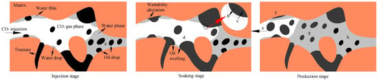
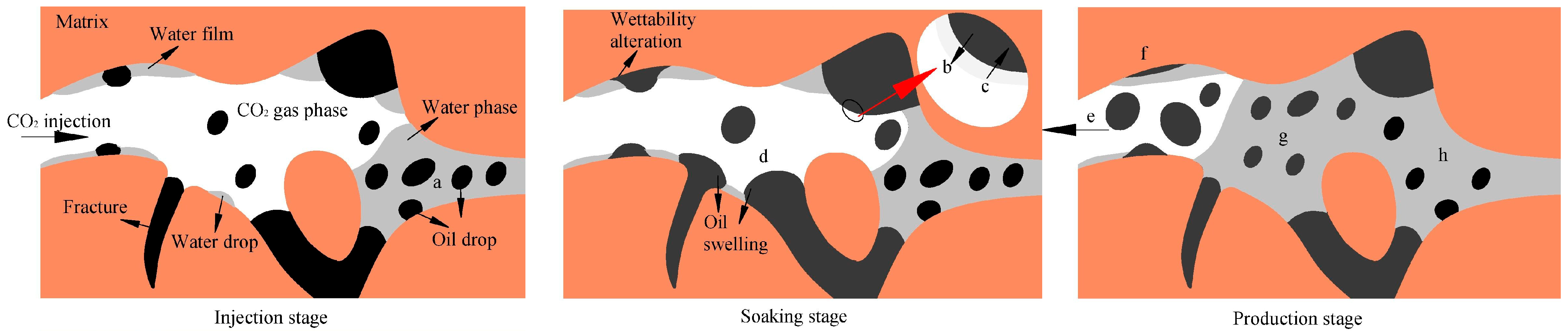
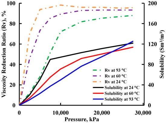
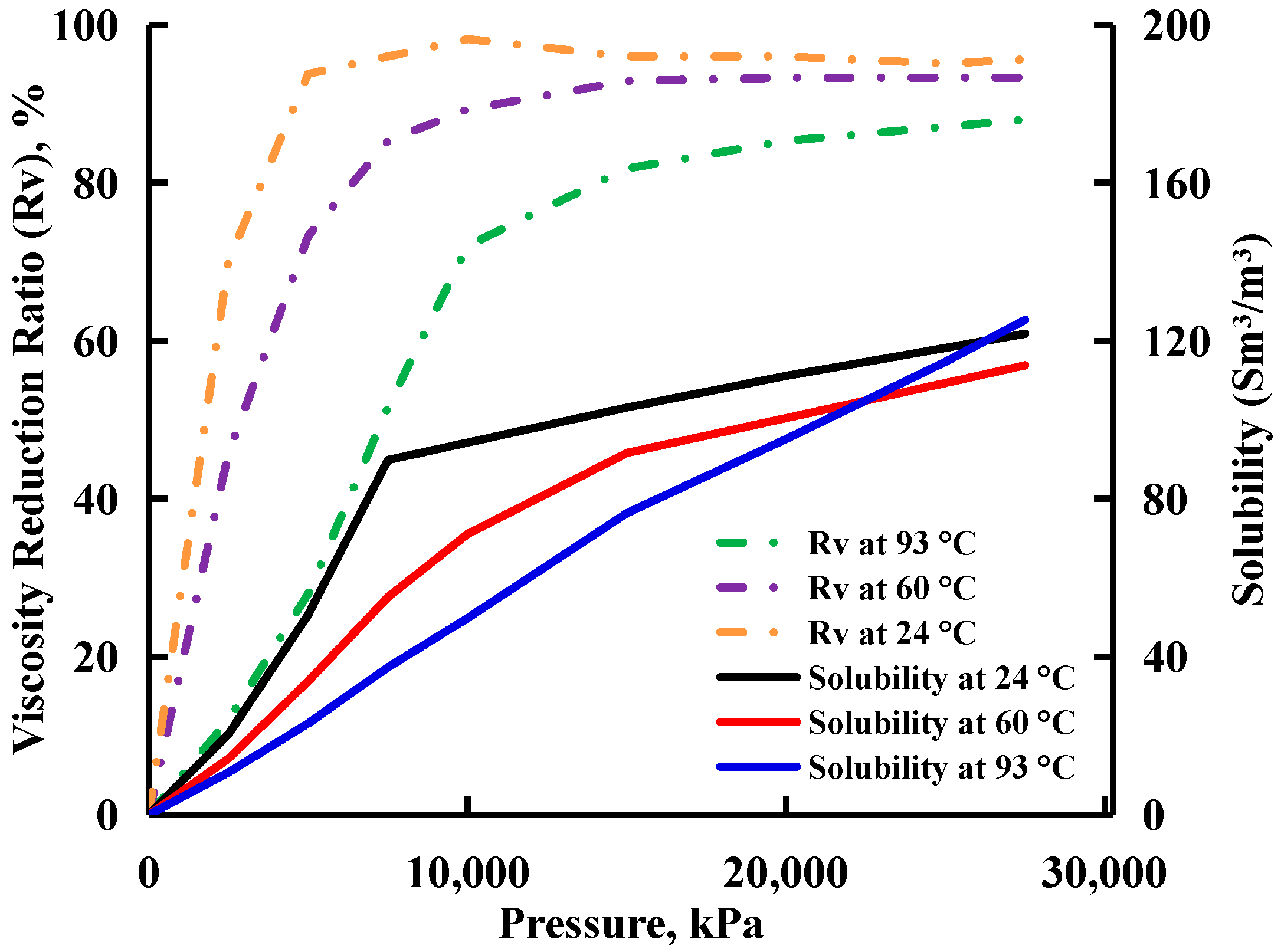
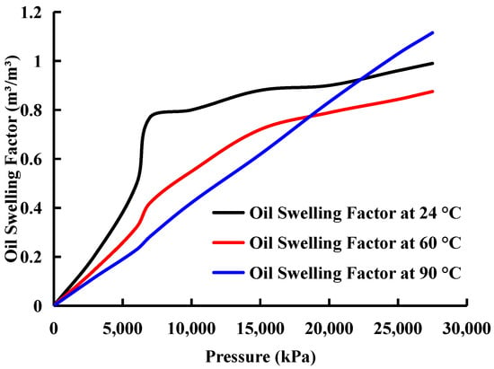
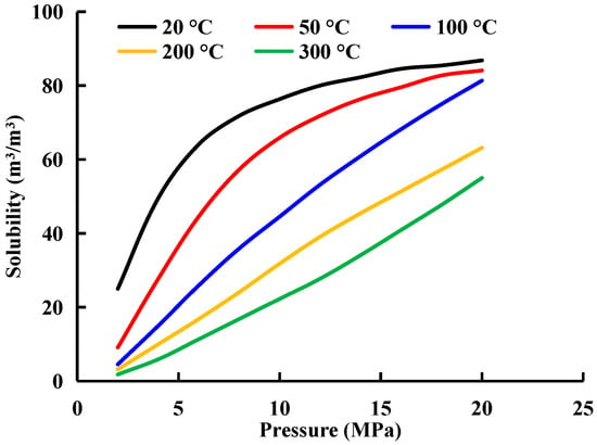
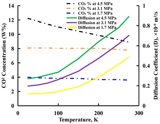
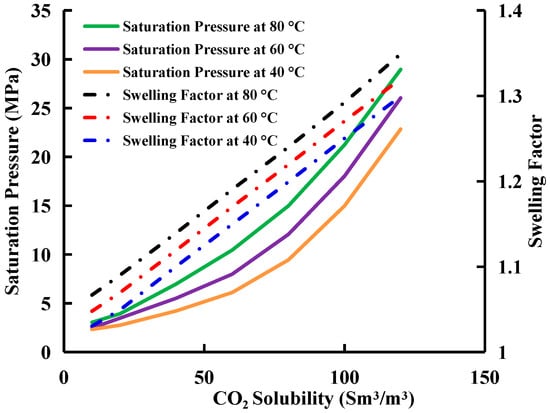
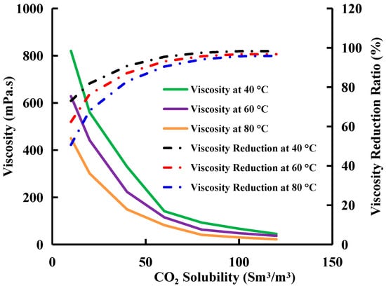
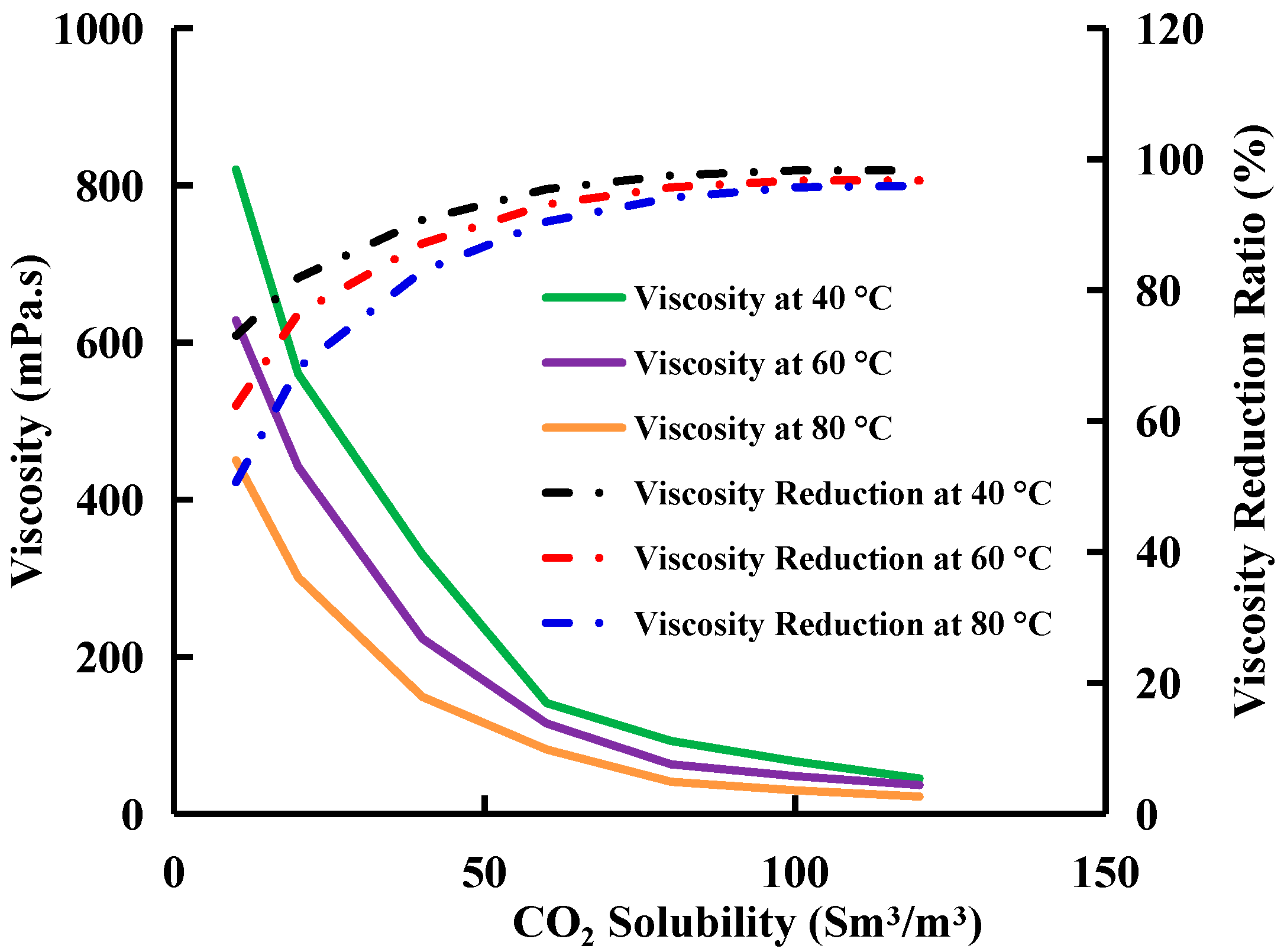
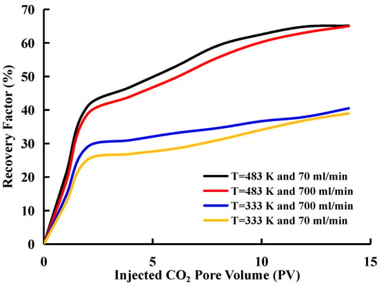
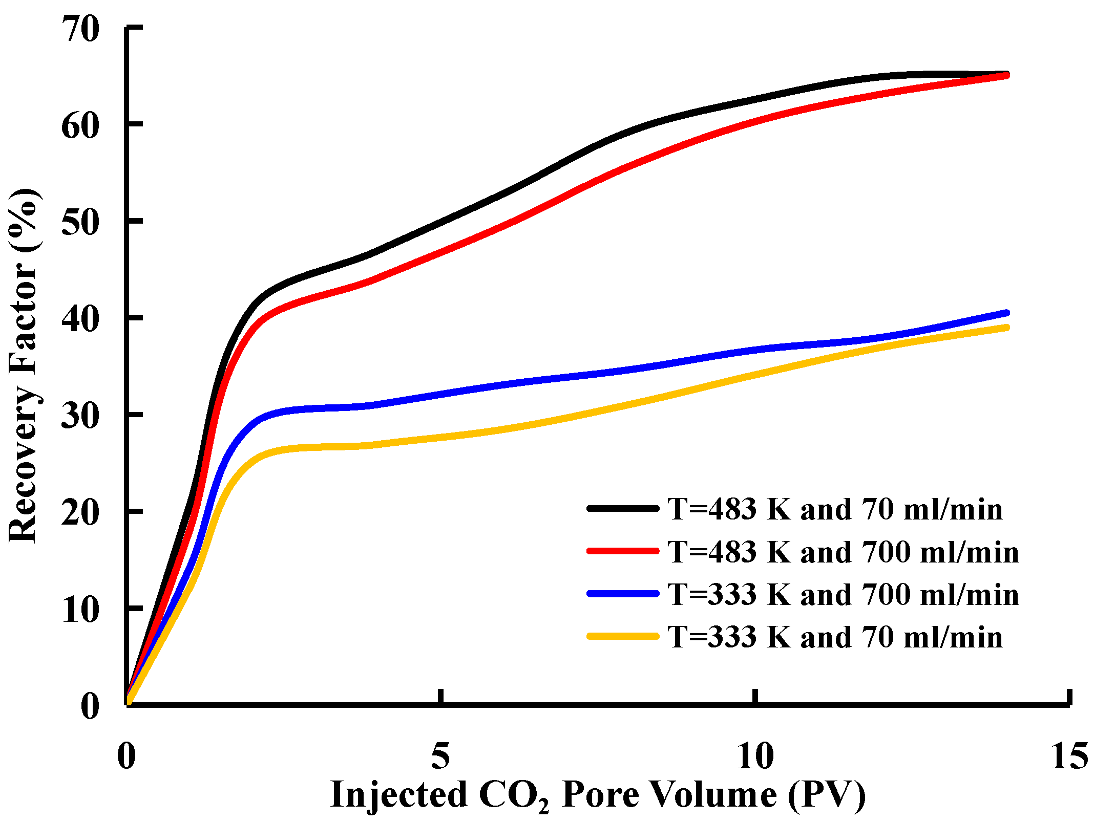
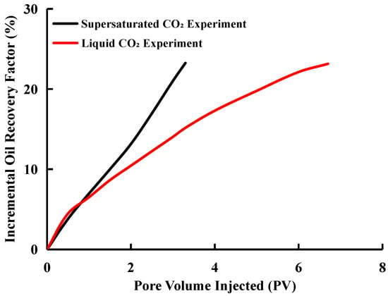
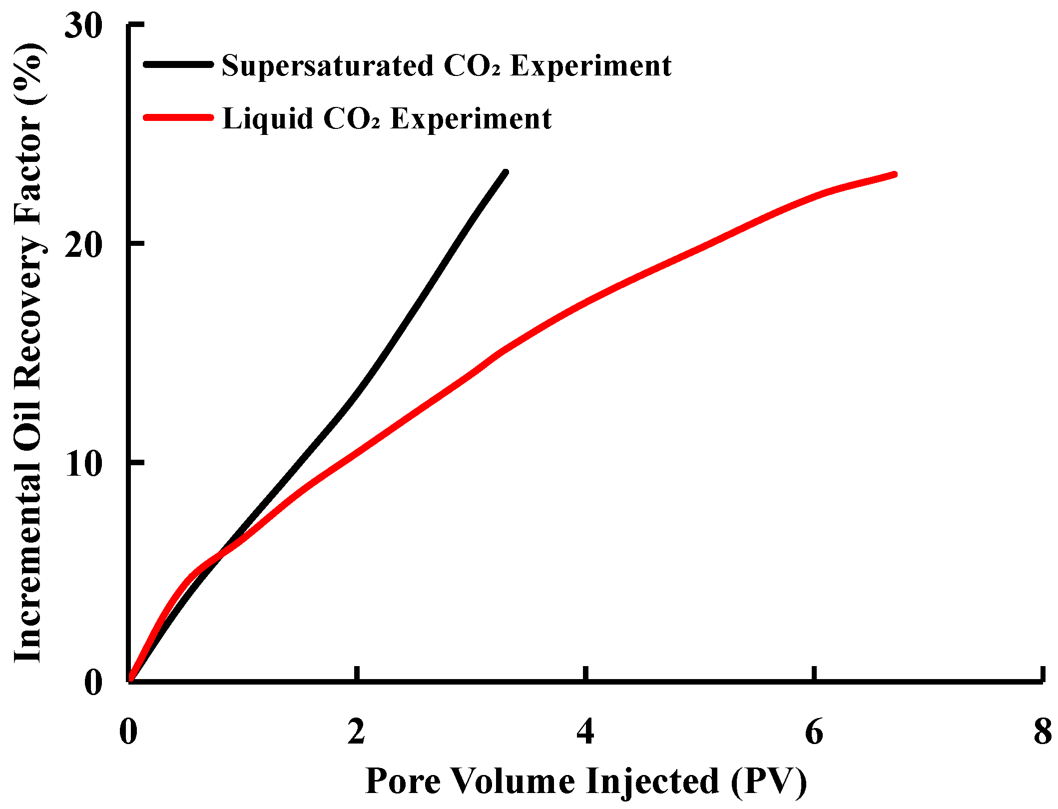
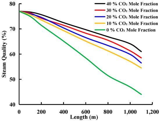
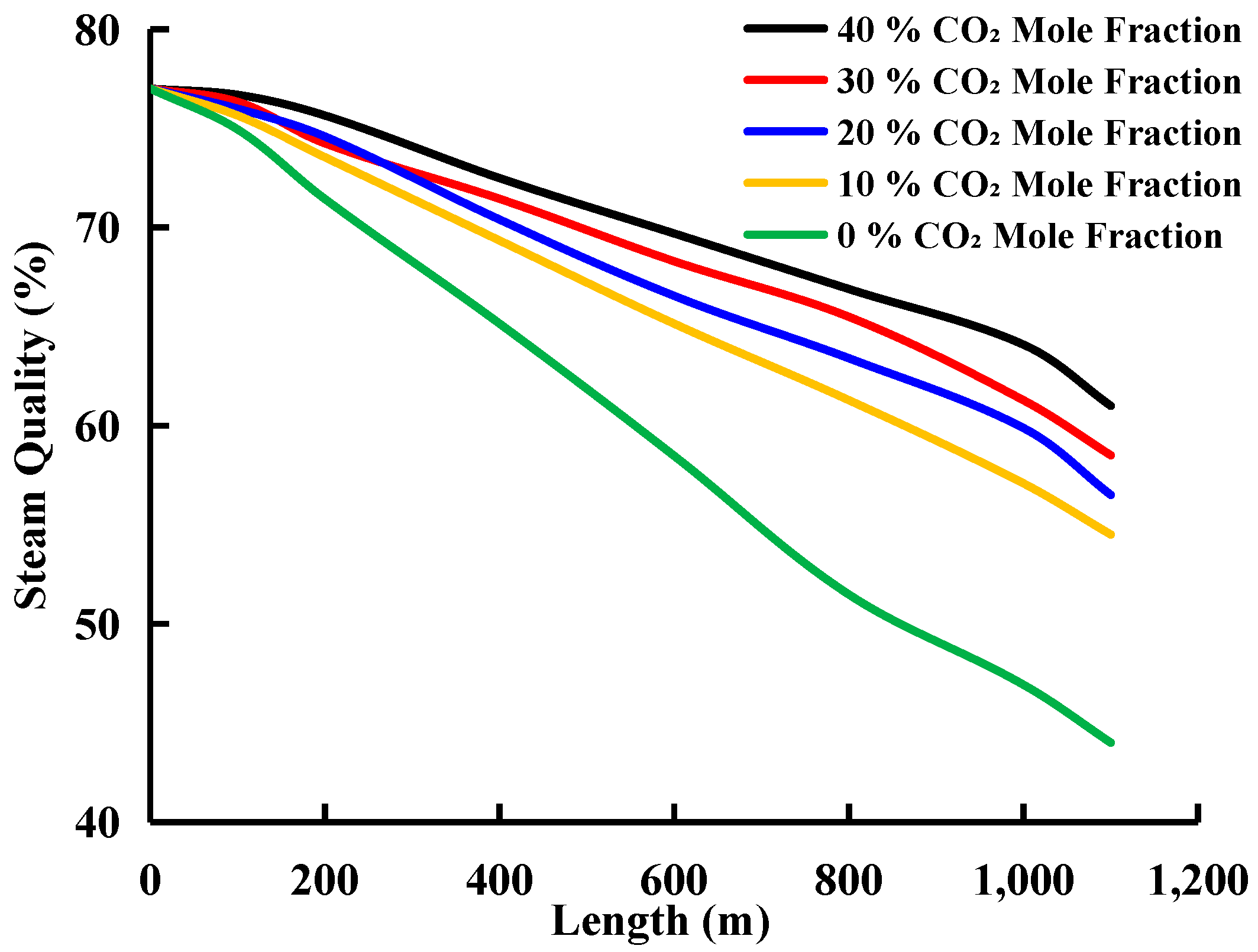
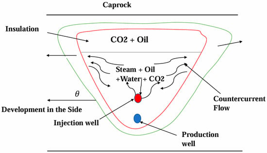
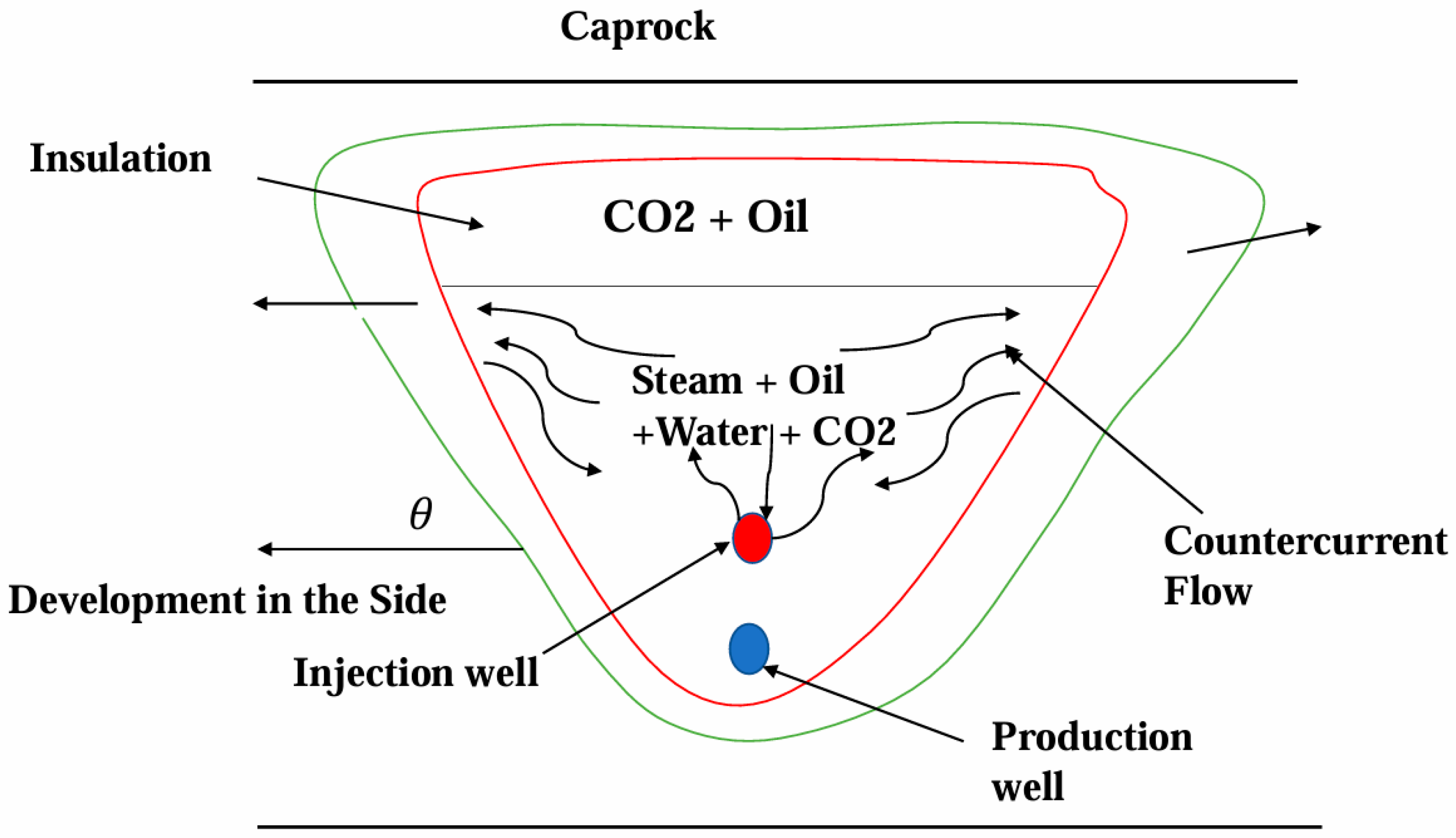
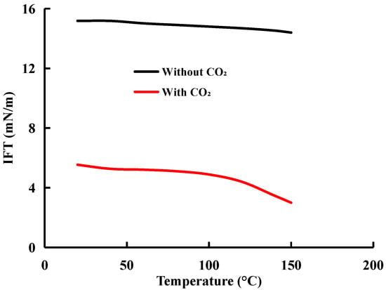
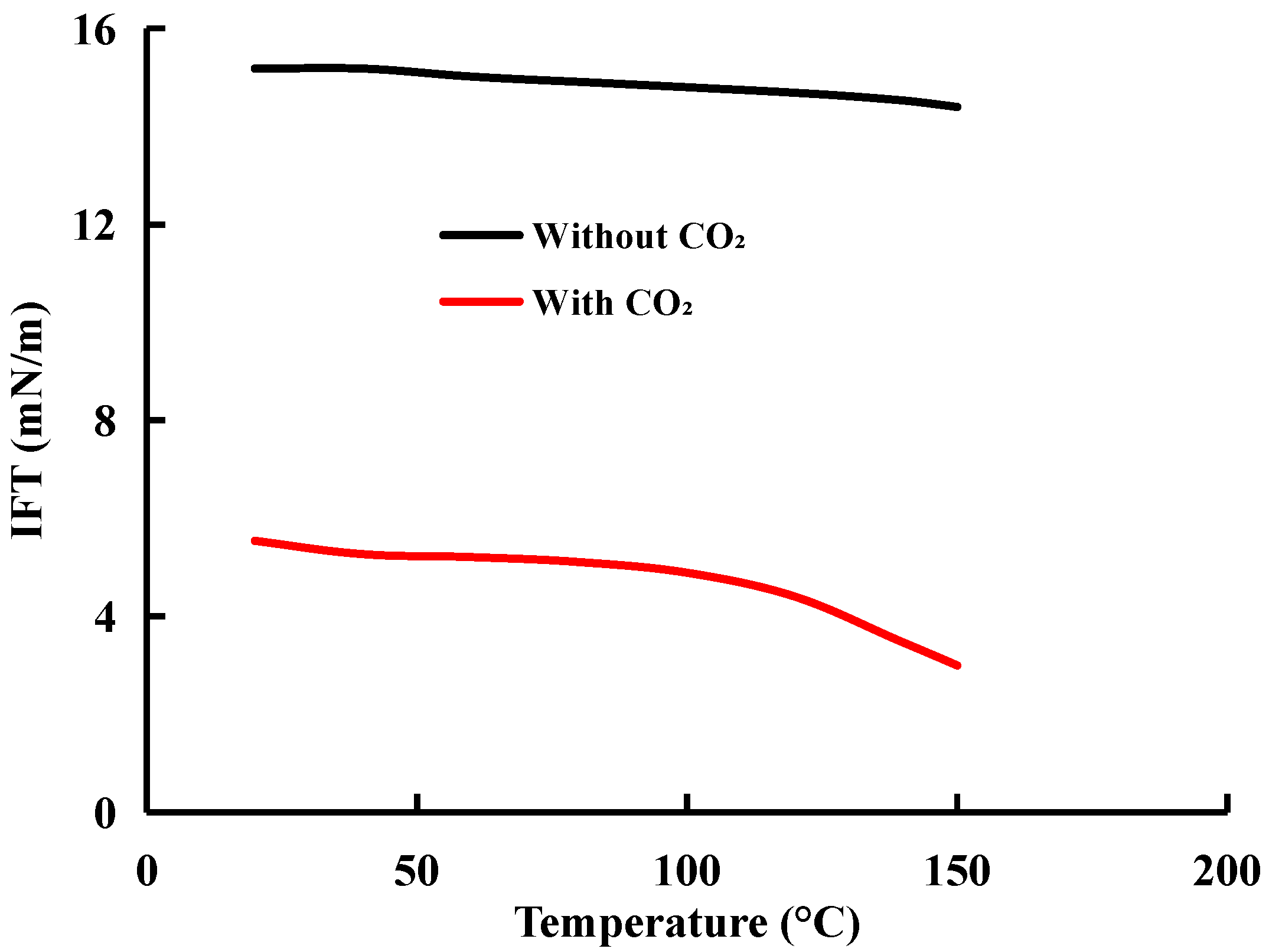
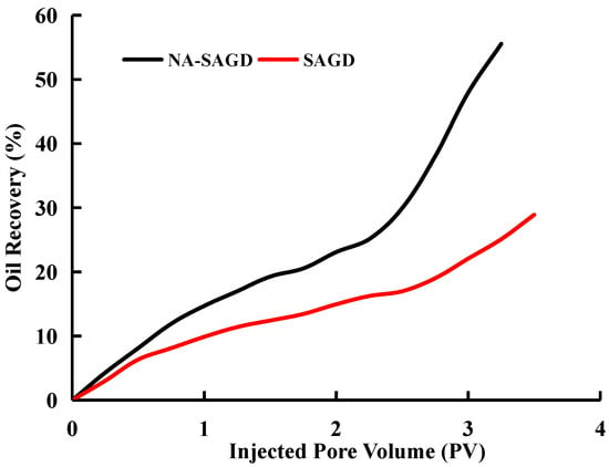
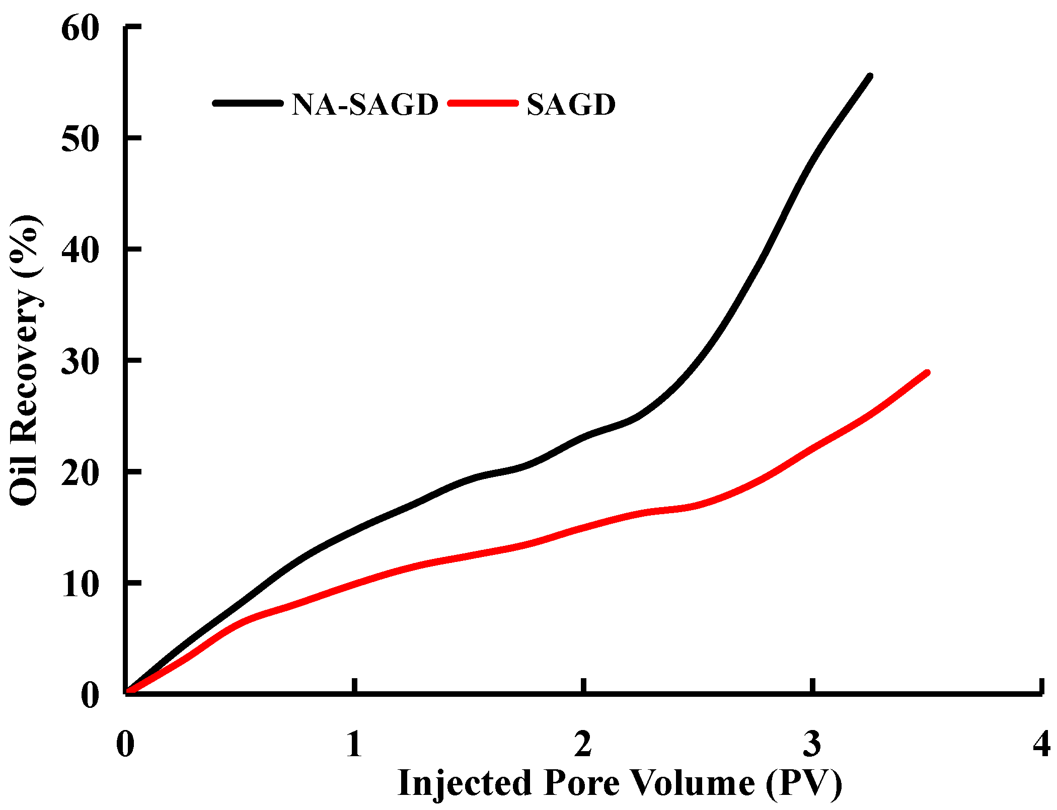
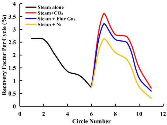
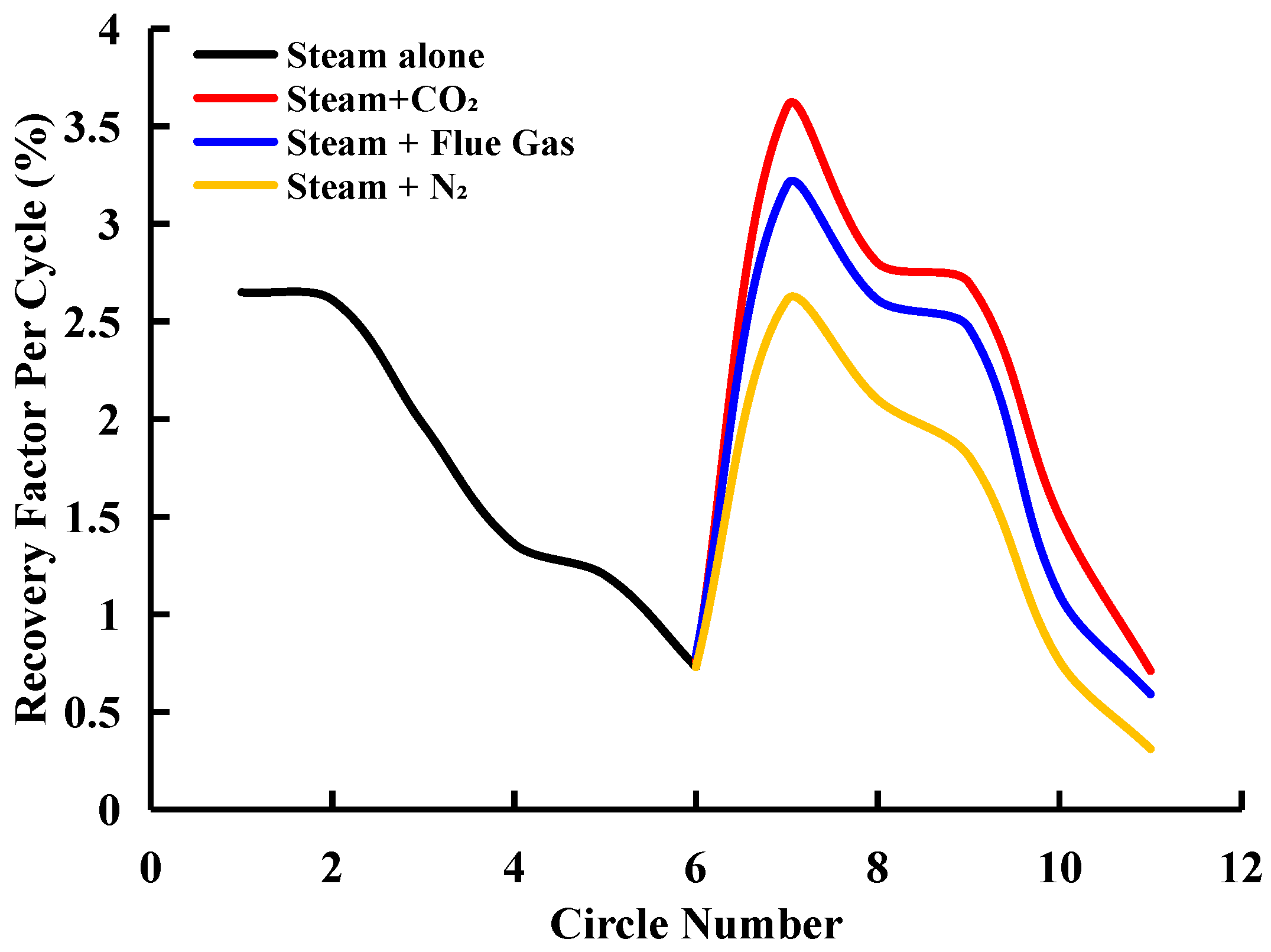
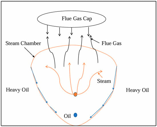
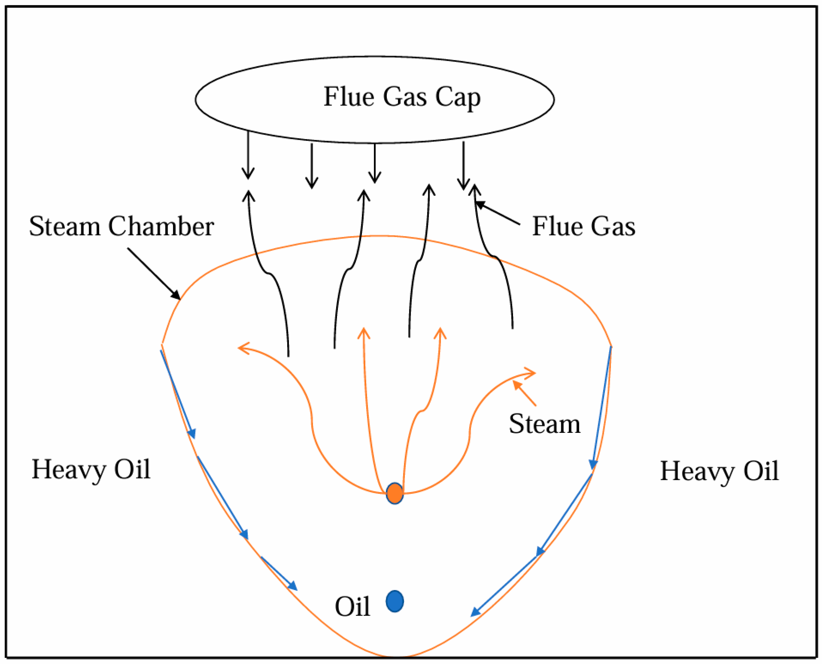

Disclaimer/Publisher’s Note: The statements, opinions and data contained in all publications are solely those of the individual author(s) and contributor(s) and not of MDPI and/or the editor(s). MDPI and/or the editor(s) disclaim responsibility for any injury to people or property resulting from any ideas, methods, instructions or products referred to in the content. |
© 2026 by the authors. Licensee MDPI, Basel, Switzerland. This article is an open access article distributed under the terms and conditions of the Creative Commons Attribution (CC BY) license.