


Abstract
Ensuring the integrity of weld seams in pipeline components is critical for the safe and reliable transportation of oil and natural gas. This paper presents a systematic failure investigation of a cracked weld in a reducer located at a natural gas transmission station in Western China, aiming to identify the failure mechanism and assess its implications for pipeline safety management. A comprehensive analysis was conducted using macroscopic examination, chemical composition analysis, mechanical property testing, metallographic observation, and microscopic fracture characterization. The results reveal that the heat-affected zone (HAZ) exhibited abnormally high hardness (up to 588 HV0.1), indicating insufficient toughness that made it susceptible to cracking. The base metal showed a high carbon equivalent (CEV), placing it in the “difficult-to-weld” category and increasing its sensitivity to improper welding thermal cycles. On-site investigation further identified significant deficiencies in welding process control, including inadequate preheating, improper interpass temperature management, and insufficient post-weld heat treatment (PWHT). These deficiencies allowed welding residual stresses to persist and failed to mitigate the hardened HAZ microstructure. The combination of poor material weldability and inadequate on-site welding practices ultimately led to brittle fracture under service conditions. This failure highlights a critical vulnerability in pipeline transportation infrastructure and underscores the necessity of strict adherence to qualified welding procedures for high-carbon-equivalent steels. The findings provide practical guidance for enhancing welding quality control and ensuring the long-term operational safety of natural gas pipeline systems.
1. Introduction
As primary global energy sources and chemical raw materials, the safe, efficient, and stable storage and transportation of oil and natural gas are critical to ensuring national energy security and industrial stability [1,2,3,4]. Within the vast oil and gas storage and transportation system, pipeline networks function as the “blood vessels,” while pipe fittings act as the “joints” for connection and redirection. Among these, reducers—key fittings used to connect pipelines of different diameters—are widely employed at pump station inlets and outlets, filter connections, and branch pipelines. Their structural integrity is directly tied to the operational safety of the entire pipeline network [5,6,7].
However, during long-term service, the weld seams of reducers have become one of the weak points prone to failure. Due to the abrupt change in geometry, significant stress concentration occurs at the weld seams of reducers when they are subjected to internal pressure, temperature fluctuations, external loads, and fluid pulsation [8,9,10,11,12]. This inherent mechanical characteristic makes the area highly susceptible to fatigue crack initiation or brittle fracture originating from manufacturing defects. Once a weld seam fails and fractures, the consequences can range from medium leakage, production shutdown, and economic losses to severe incidents such as fires or explosions, posing serious threats to personnel safety, the ecological environment, and social assets.
The causes of weld seam failure in reducers are complex, resulting from the coupled effects of material, mechanical, process, and environmental factors. Specifically, the primary contributing factors can be summarized as follows: (1) Design factors: insufficient transition curvature or inappropriate wall thickness selection, which fail to effectively mitigate stress concentration; (2) Manufacturing and welding factors: poor weld formation, defects such as lack of penetration, porosity, and slag inclusion, as well as residual stress and embrittled microstructures caused by improper heat treatment; (3) Mechanical factors: fatigue damage under cyclic loads (e.g., pressure fluctuations, vibration) or sudden overload; (4) Environmental factors: stress corrosion cracking or corrosion fatigue induced by corrosive components in the transported medium (e.g., H2S, CO2, chloride ions); and (5) Operational and maintenance factors: inappropriate operating parameters, and failure to detect and repair defects in a timely manner [12,13,14,15,16].
Although extensive research has been conducted by scholars both domestically and internationally on pipeline integrity management and the failure of welded structures, systematic analysis of weld seam failure in reducers—particularly regarding the failure mechanisms and prevention strategies under multi-factor coupling—remains insufficient [16,17,18]. Therefore, this paper aims to systematically analyze the causes of weld seam failure in reducers used in oil and gas storage and transportation. It will delve into the failure mechanisms from multiple dimensions, including material and environmental factors. Finally, based on the analysis results, targeted recommendations for design optimization, key points for manufacturing quality control, and strategies for in-service inspection and maintenance will be proposed, with the goal of providing theoretical foundations and practical references for enhancing the safety and reliability of oil and gas storage and transportation pipelines.
2. Overview
On 24 June 2023, the gathering and transmission pipeline was put into operation. The pipeline starts at the well and ends at the Manshen 3-1 valve group. The pipeline operates at a pressure of 4.13 MPa and a temperature of 22 °C. It transports oil, gas, and water. The average daily oil production is 39.6 tons, the average daily gas production is 13,305.4 cubic meters, the average daily water production is 1.6 tons, and the H2S content is 13,333~29,000 ppm. The surface pipelines at the well site are made of 20G steel, with a diameter of DN100, and are manufactured according to “Seamless Steel tubes and pipes for high pressure boilers”. The underground pipeline at the well site is a flexible composite pipe, and the two are connected by a steel conversion joint. The joint material is 20G, and the manufacturing standard is in accordance with “ Steel buttwelding pipe fittings—Technical specification”.
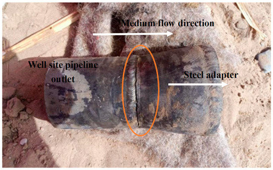
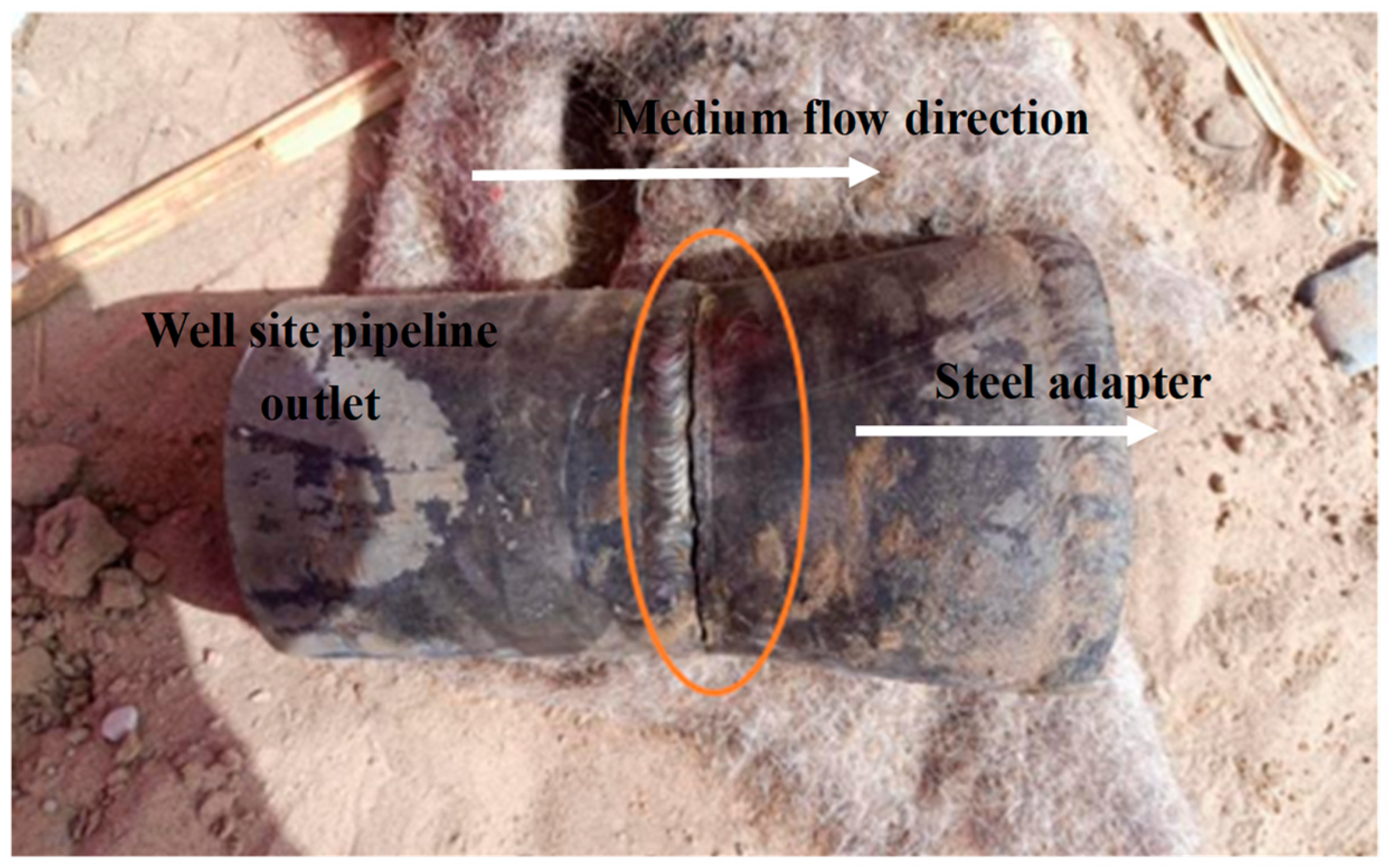
On 18 October, a crack occurred at the weld toe of the circumferential weld on the small end side of the upstream reducer of the steel conversion joint of the gathering pipeline. The failure location was in the direction from 9 o’clock to 3 o’clock, as shown in Figure 1.
Figure 1.
Failed sample.
3. Macroscopic Morphological Analysis
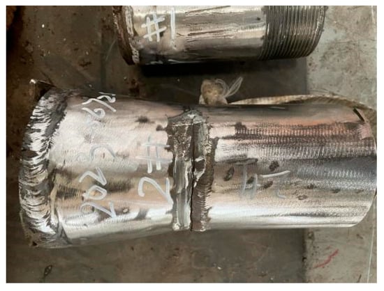
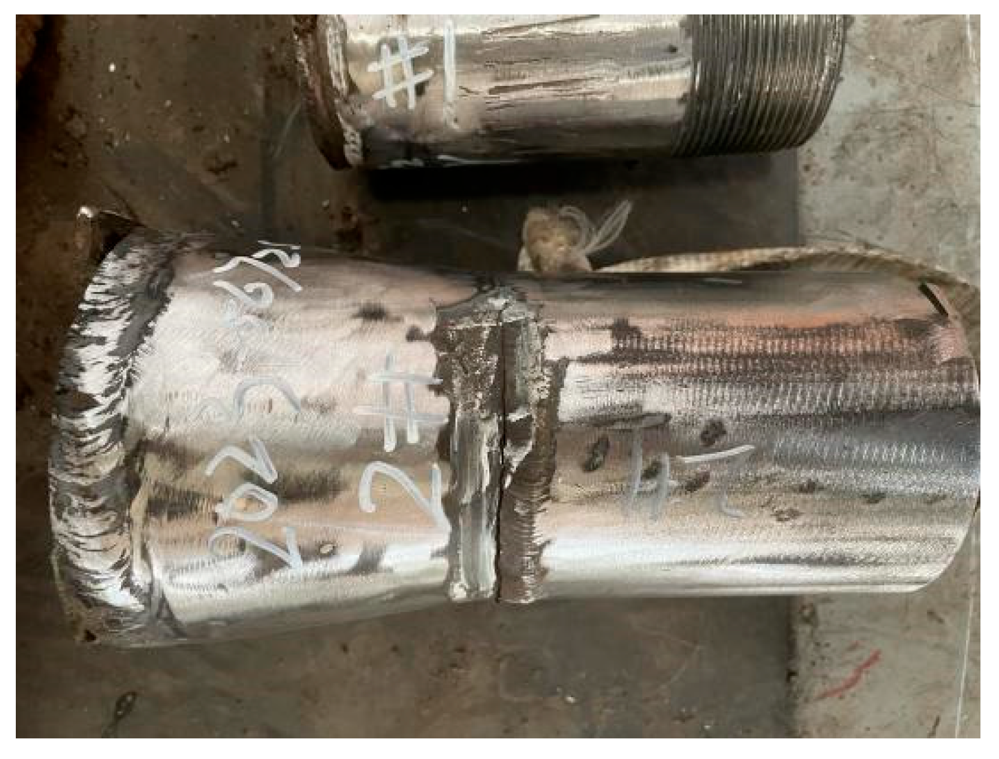
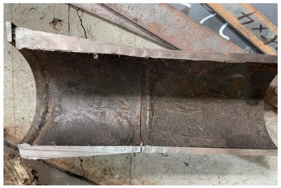
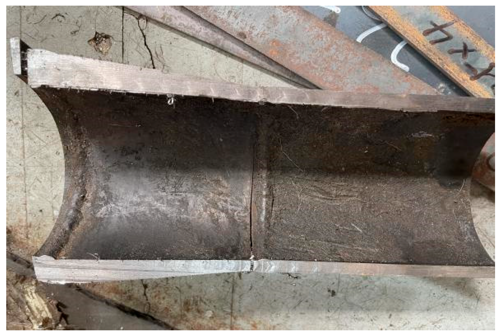
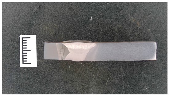
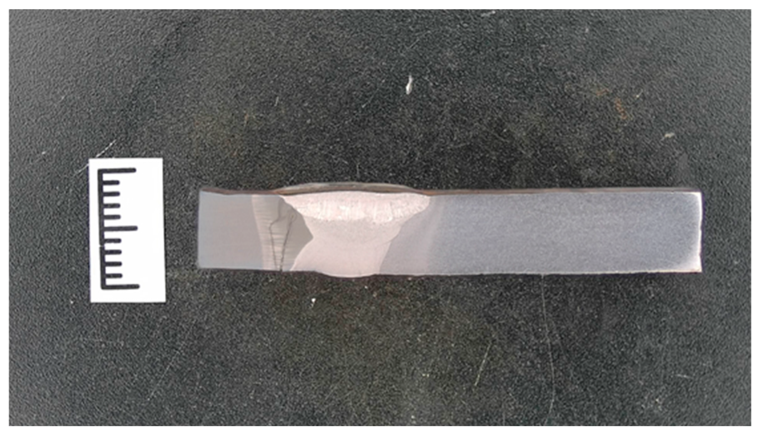
The submitted test specimens consisted of a straight pipe and a reducer, each approximately 10 cm in length. The circumferential weld on the reducer side showed a crack, with no obvious plastic deformation at the crack. There were no signs of overheating or weld spatter at the lower part of the weld, as shown in Figure 2. Upon longitudinal sectioning of the specimen, the circumferential weld between the straight pipe and the reducer was well-formed, and no obvious localized corrosion was observed on the inner surface, as shown in Figure 3.
Figure 2.
Macroscopic morphology of the outer surface of the sample.
Figure 3.
Macroscopic morphology of the inner surface of the sample.
4. Geometric Dimension Measurement
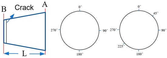
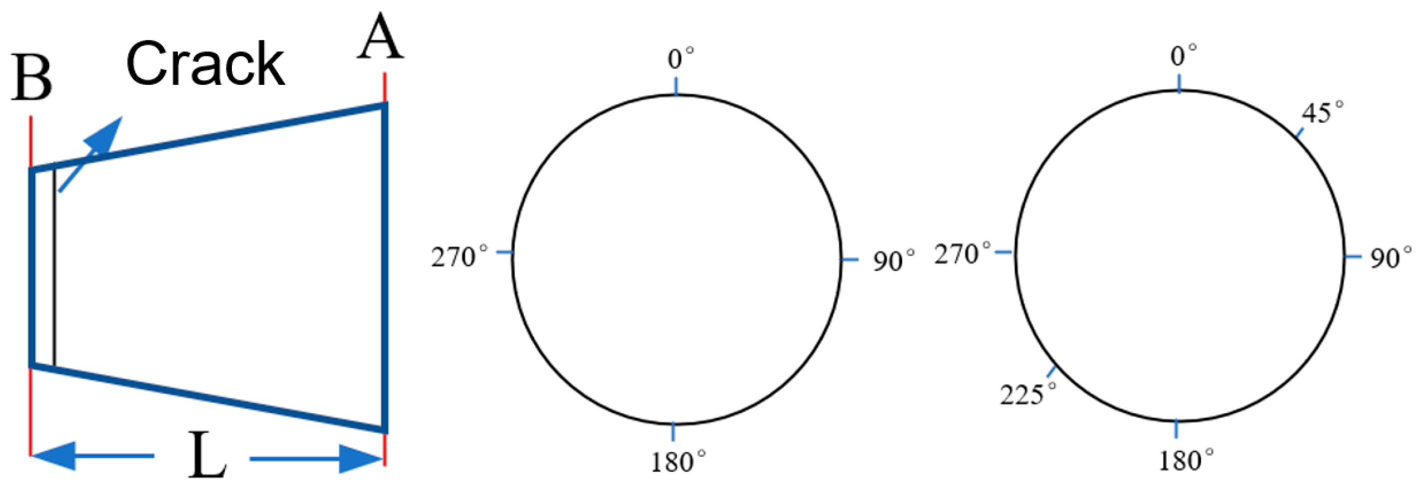
The outer diameter and wall thickness of the reducer were measured using vernier calipers and a thickness gauge. The measurement locations are shown in Figure 4, and the measurement results are shown in Table 1. The measurement results show that the geometric dimensions of the reducer conform to the requirements of “ Steel buttwelding pipe fittings—Types and parameter”.
Figure 4.
Schematic diagram of the measurement position for large and small heads.
Table 1.
Measurement results of geometric dimensions of the reducer/reducer.
5. Non-Destructive Testing
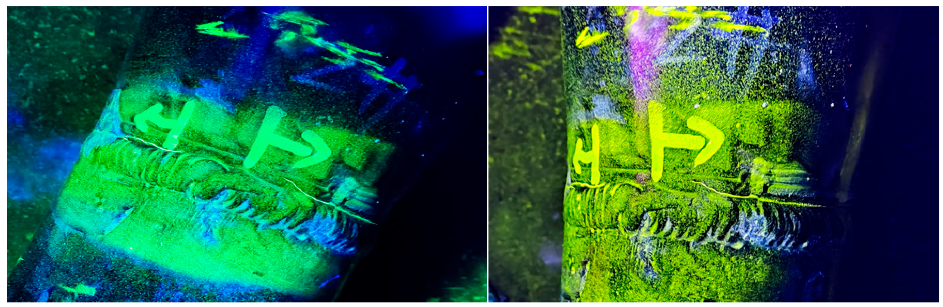
According to “Magnetic Particle Testing Standard Guide E709”, magnetic particle testing was performed on the outer surface of the reducer. It was found that no obvious cracks were found except at the location of the weld crack, as shown in Figure 5.
Figure 5.
Magnetic particle inspection photograph of the outer surface of the reducer.
According to the standard “Nondestructive testing standard of oil and gas steel pipeline “, ultrasonic testing was performed on the circumferential weld of the sample. The results showed that no abnormalities were found except for the excessive signal at the cracked area, as shown in Table 2. According to “ Standard Guide for Radiographic Examination Using Industrial Radiographic Film”, radiographic testing was performed on the circumferential weld of the sample. The results showed that no other obvious defects were found except for the unqualified cracked area, as shown in Table 3.
Table 2.
Ultrasonic test results.
Table 3.
Results of X-ray Detection.
6. Chemical Composition Analysis
According to “ Carbon and low-alloy steel—Determination of multi-element contents—Spark discharge atomic emission spectrometric method (routine method)”, two samples, one for straight tubes and one for reducing heads, were taken for chemical composition analysis. Their chemical compositions were analyzed using an ARL 4460 direct-reading spectrometer, and the results are shown in Table 4. Table 4 shows that the chemical composition of the straight tubes meets the requirements expect C and Cr chemical compositions.
Table 4.
Results of chemical composition analysis (wt%).
7. Metallographic Analysis
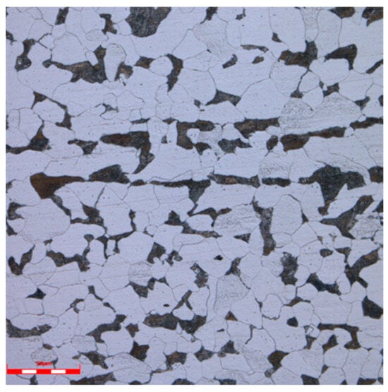
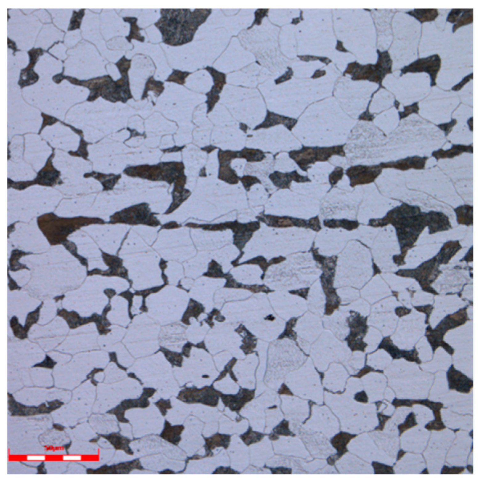
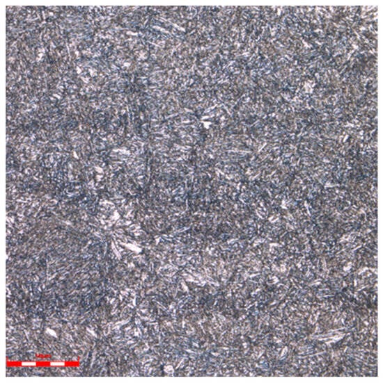
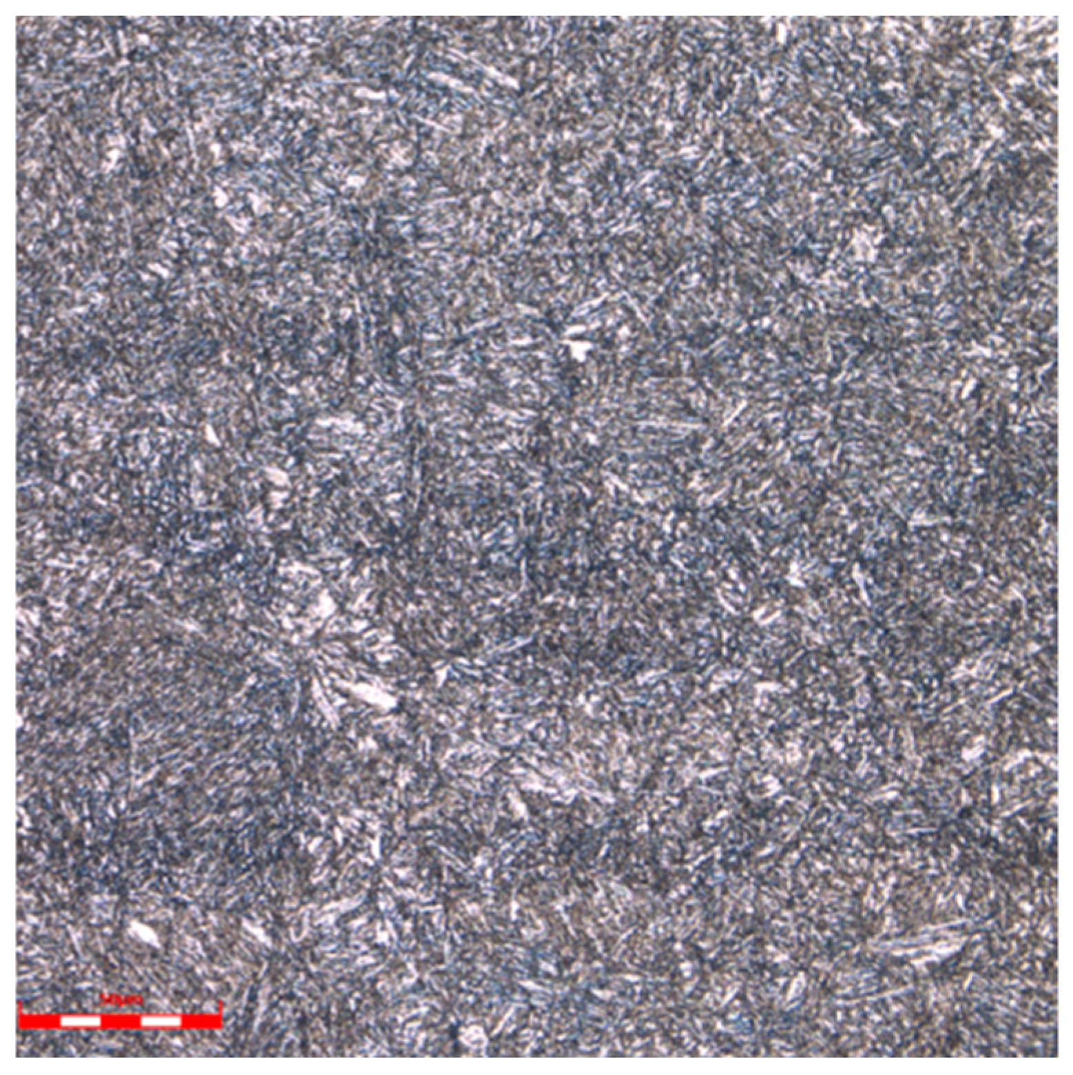
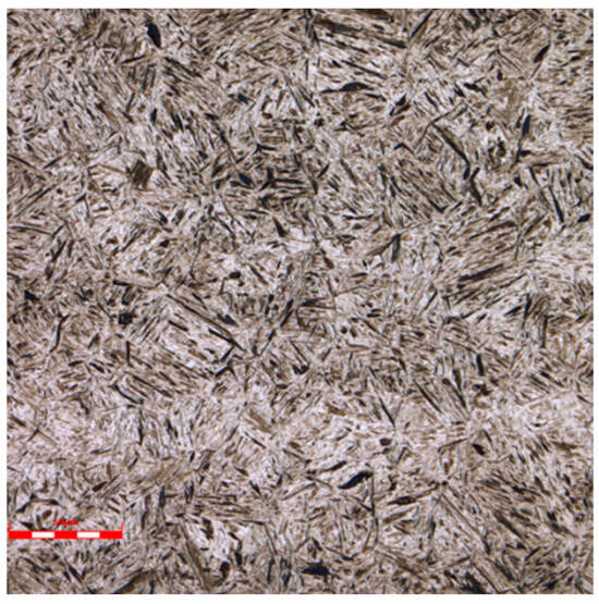
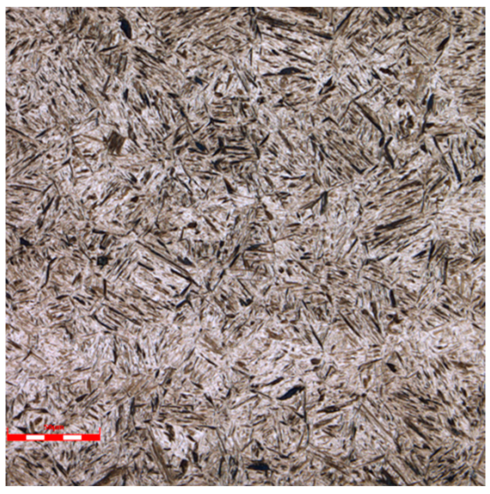
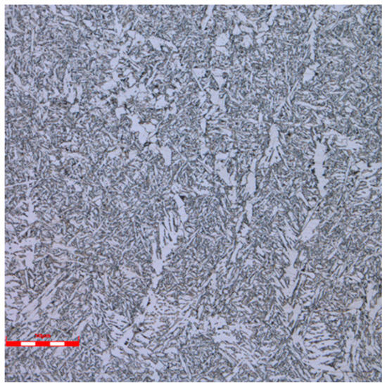
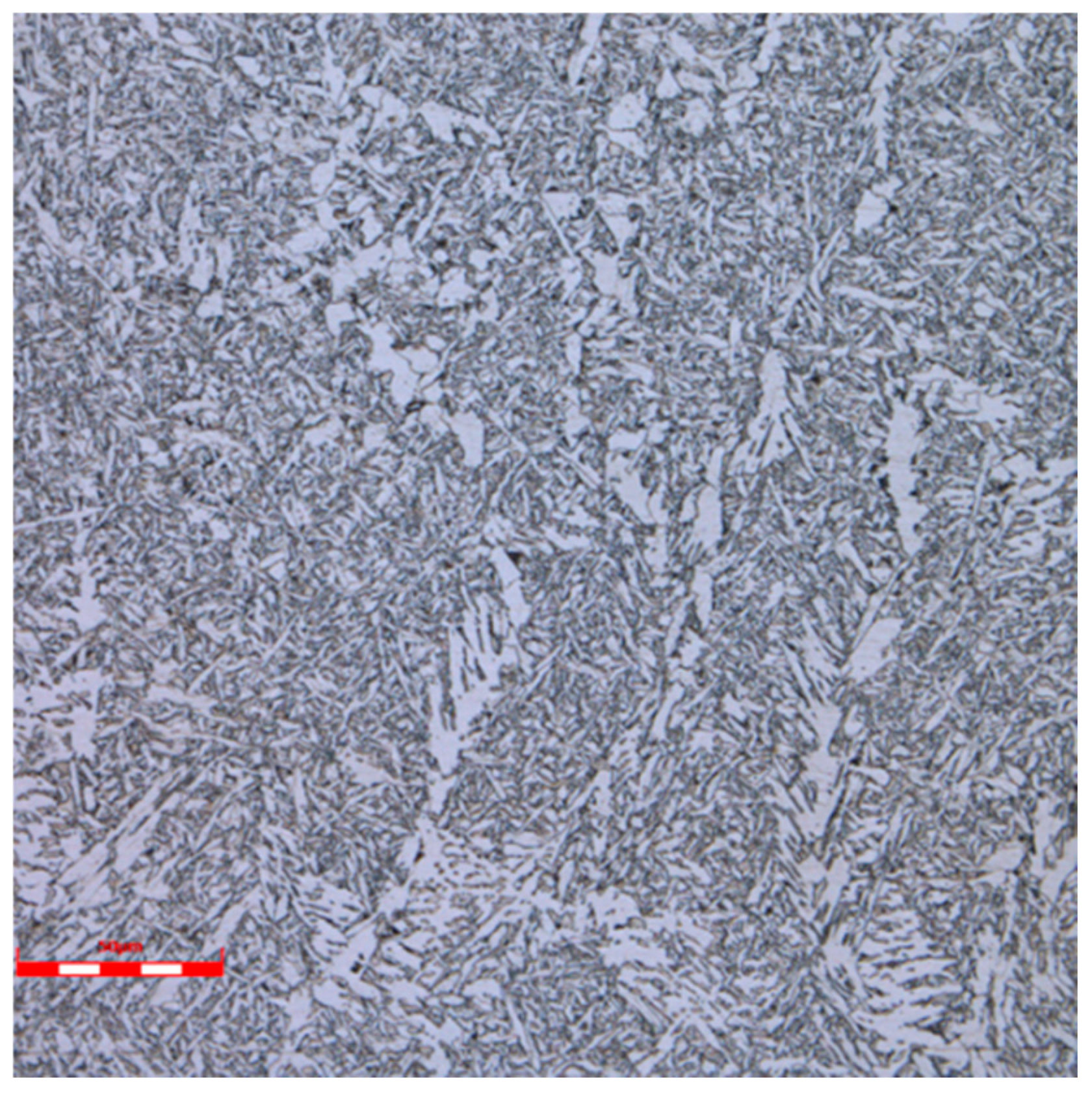
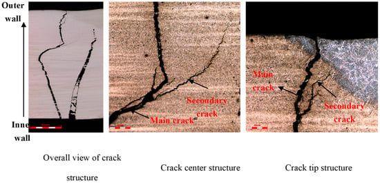
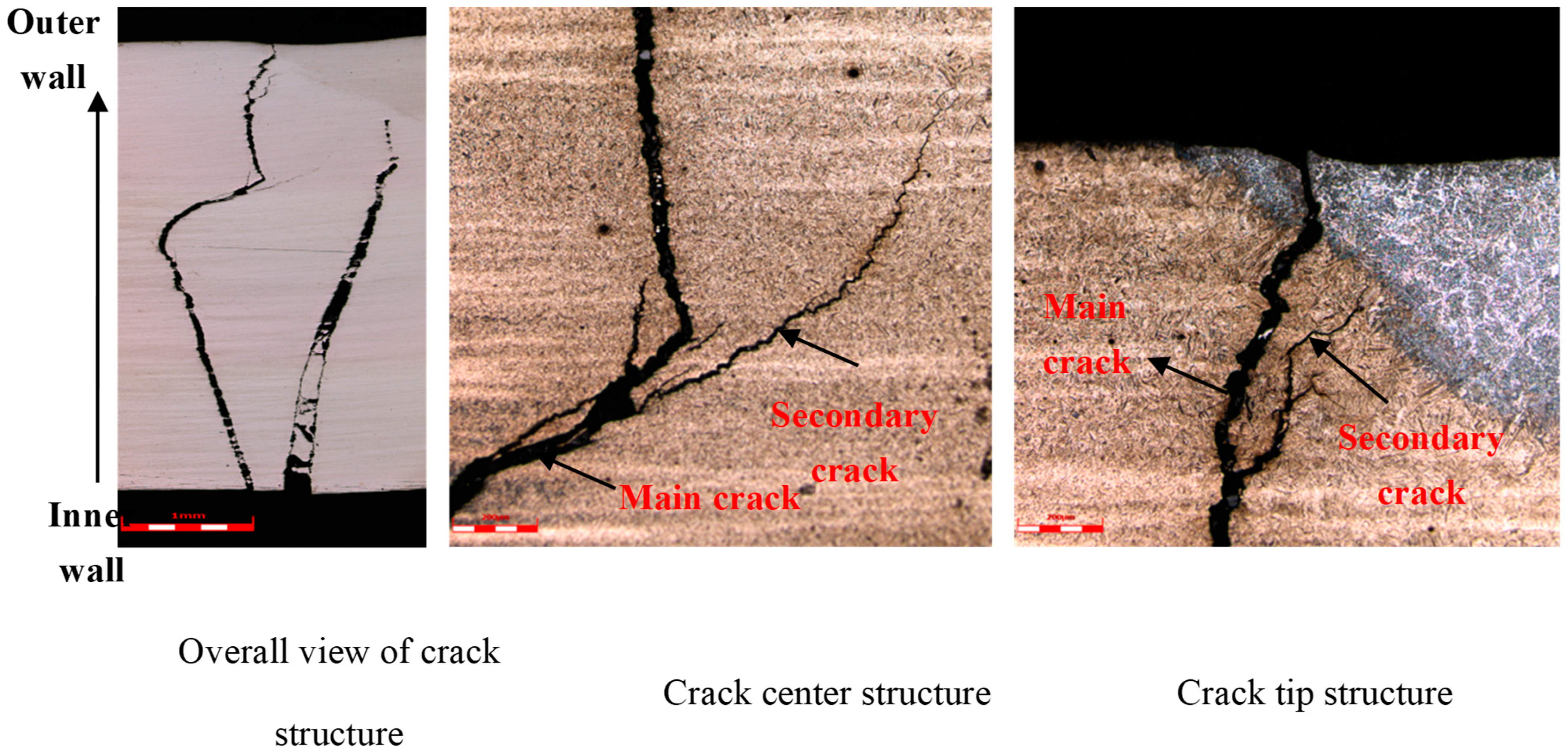
Metallographic samples were taken from the straight pipe, reducer, and circumferential weld, totaling six samples. According to” Inspection methods of microstructure for metals”, “ Determination of ferrite grain size for cold rolled low carbon steel sheets”, and “ Standard Test Methods for Determining the Inclusion Content of Steel “, the samples were analyzed for microstructure, grain size, and non-metallic inclusions using a MeF3A metallographic microscope and an OLS 4100 laser confocal microscope. The results are shown in Table 5 and Table 6, and the metallographic structures are shown in Figure 6, Figure 7, Figure 8 and Figure 9. The results show that the reducer’s metallographic structure is tempered sorbite with a grain size of 9.5; the straight pipe’s metallographic structure is ferrite and pearlite with a grain size of 7.5; and the circumferential weld exhibits a combination of acicular ferrite and polygonal ferrite. Observation of the cross-sectional sample of the crack revealed two cracks located in the heat-affected zone, extending from the inner wall to the outer wall, exhibiting predominantly transgranular morphology, with fewer secondary cracks and bifurcations, as shown in Figure 10 and Figure 11. The long crack originated from the inner wall, penetrated the wall thickness, and displayed a distinct folded morphology; the short crack also originated from the inner wall, with a thicker root and a thinner tip.
Table 5.
Metallographic Test Results of Base Material.
Table 6.
Metallographic test results of circumferential welds.
Figure 6.
Straight tube microstructure (50 μm).
Figure 7.
Microstructure of large and small heads (50 μm).
Figure 8.
Tissue of the heat-affected zone of the large and small heads (50 μm).
Figure 9.
Weld structure of the reducer weld (50 μm).
Figure 10.
Crack morphology at low magnification (1 mm).
Figure 11.
Microscopic morphology of the crack (The scale bars from left to right are 1 mm, 200 μm, and 200 μm, respectively).
8. Mechanical Property Test
8.1. Mechanical Impact Test
According to GB/T229-2020 “Metallic materials—Charpy pendulum impact test method”, longitudinal Charpy V-notch impact specimens were taken, with 3 specimens each for straight tubes and reducers, for a total of 6 specimens. The impact performance results of the specimens are shown in Table 7. As can be seen from Table 7, the impact test results of straight tubes meet the requirements of GB 5310-2017 standard, and the impact test results of reducers meet the requirements of GB/T 13401-2017 standard.
Table 7.
Charpy Impact Test Results.
8.2. Hardness Test
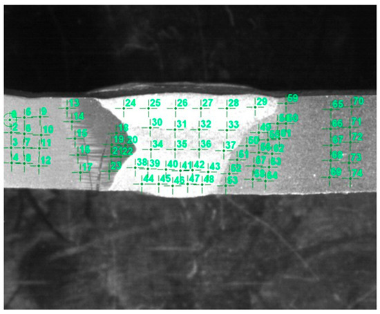
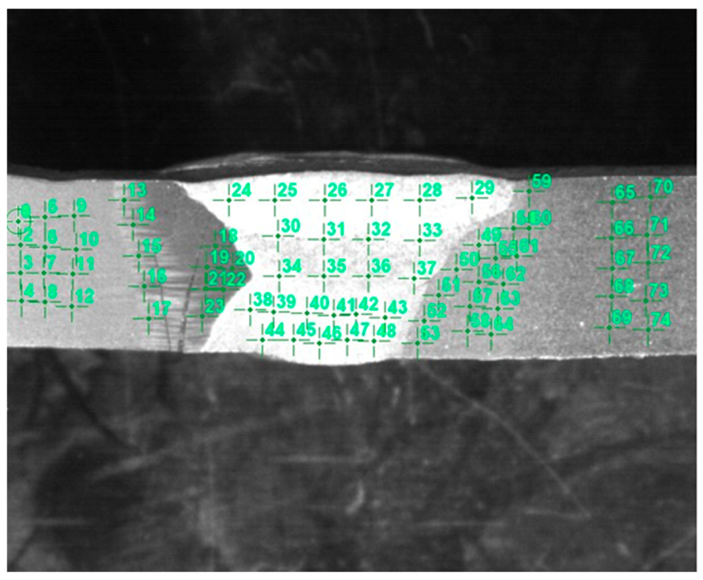
Longitudinal cross-section specimens were taken from the crack. According to “Metallic materials—Vickers hardness test—Part 1: Test method”, a DuraScan 70G5 micro Vickers hardness tester was used. 74 hardness test points were established on the reducer and taper, as shown in Figure 12. The test results are shown in Table 8. The highest hardness in the heat-affected zone on the left side of the reducer reached 588 HV0.1, which does not comply with the hardness requirement of SY/T 4083-2012 “ Technical specification for electric heat method of eliminating pipeline welding residual stress”: “The hardness value of carbon steel welds and heat-affected zones should not exceed 1.2 times the hardness of the base metal.” The macroscopic Vickers hardness of the specimens was used as a supplementary test; the hardness results were close to the microscopic hardness values of the base metal, as shown in Figure 13.
Figure 12.
Microhardness test location.
Table 8.
Microhardness test results (HV0.1).
Figure 13.
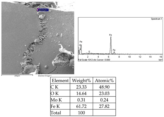
Morphology and elemental distribution at the crack root.
9. Microscopic Analysis
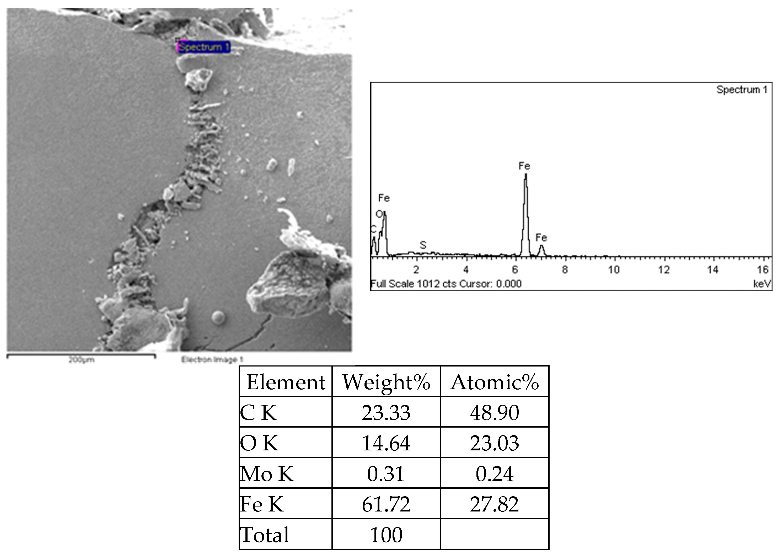
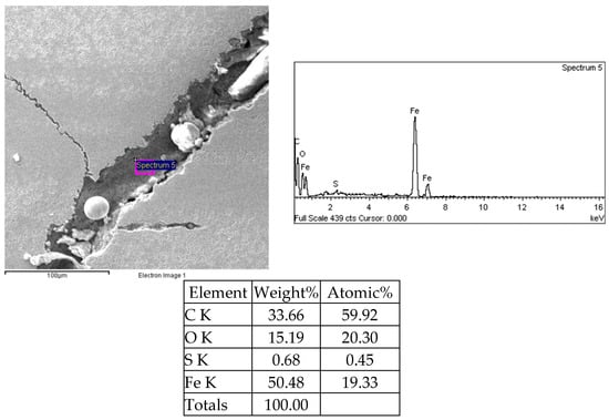
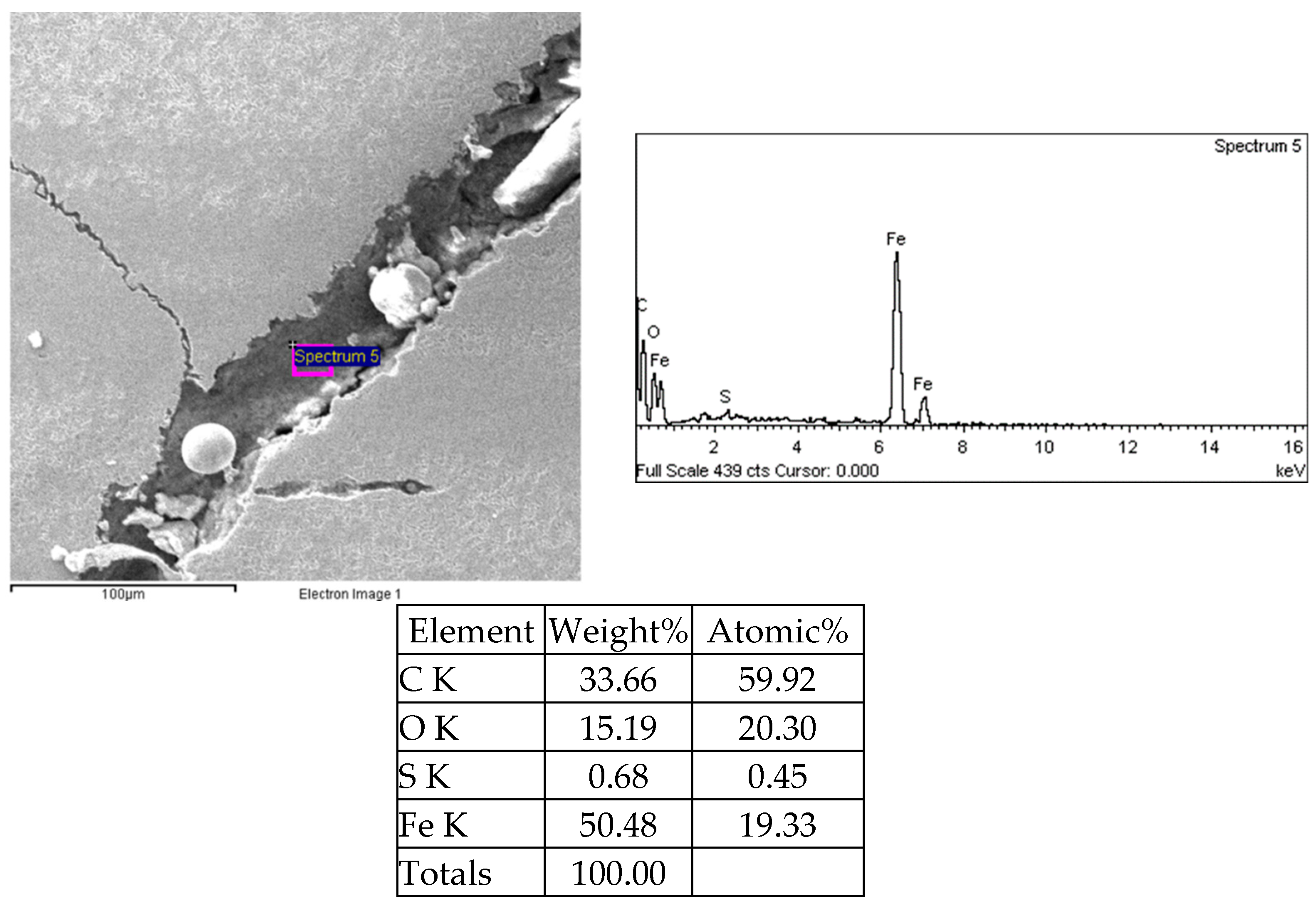
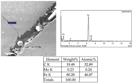
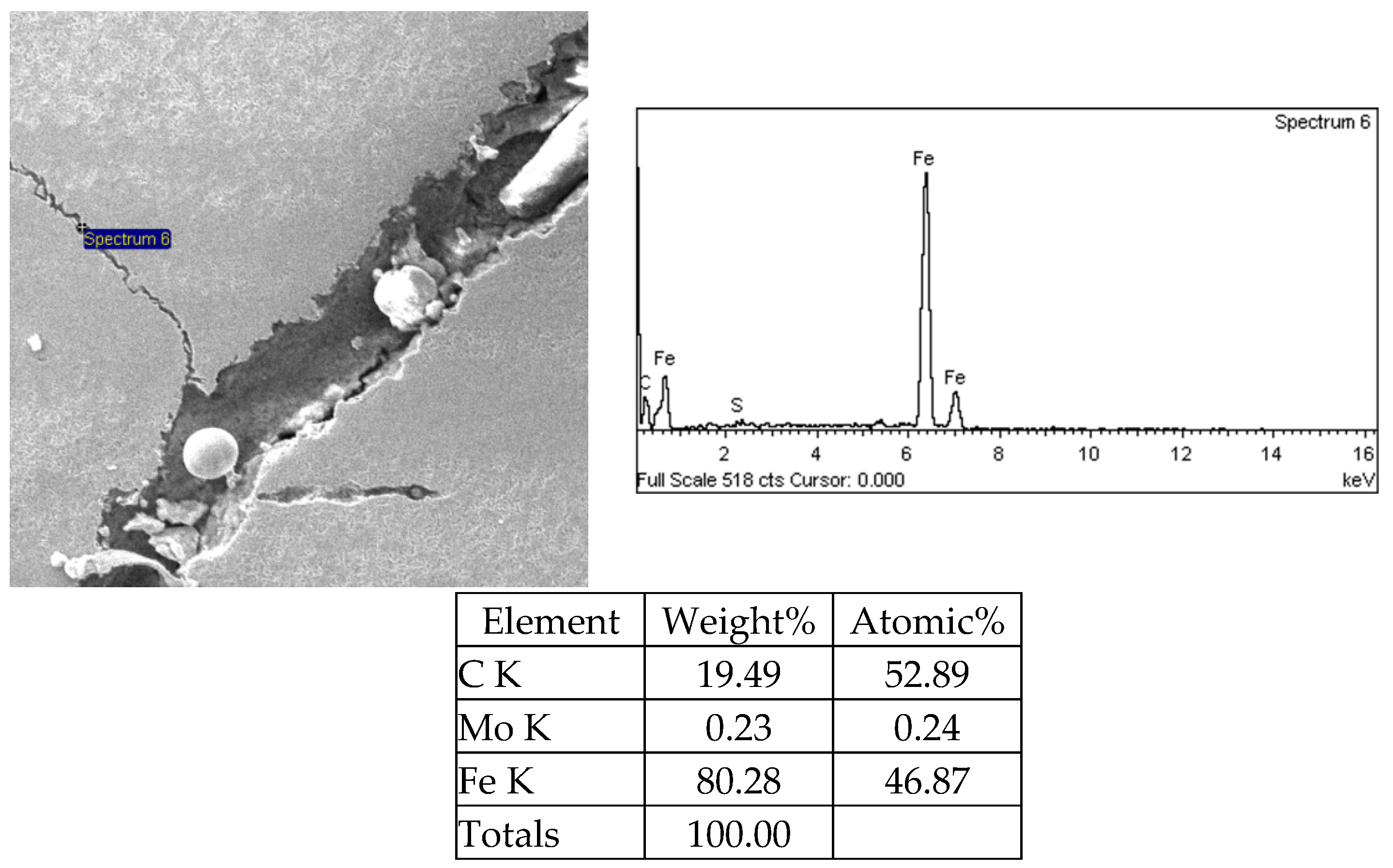
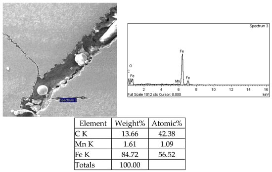
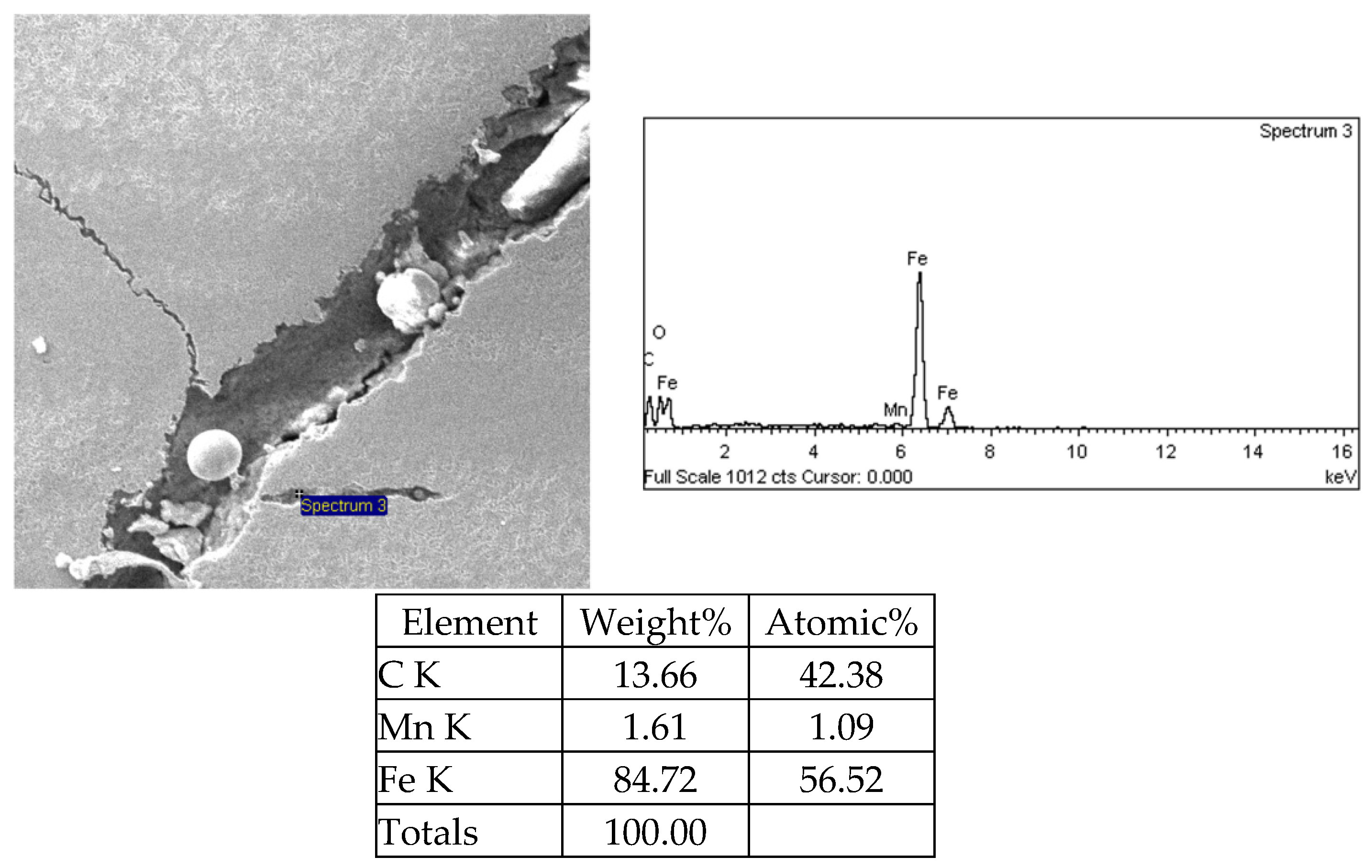
Samples were taken from the crack in the circumferential weld at the large and small ends. The morphology of the crack root, middle, and tip was observed and analyzed using a TESCAN VEGA II scanning electron microscope and its accompanying XFORD INCA350 energy dispersive spectroscopy (EDS) analyzer. The electron microscope observation time was 10 h, and 14 samples were analyzed using EDS. The results are shown in Figure 14, Figure 15 and Figure 16. The crack root and middle mainly contained C, Fe, S, and O elements, while the secondary crack tip contained C, Fe, Mo, and Mn elements, but no S element.
Figure 14.
Morphology and elemental distribution of the crack center.
Figure 15.
Morphology and elemental distribution of the secondary crack tip (left).
Figure 16.
Morphology and elemental distribution of the secondary crack tip (right).
10. Comprehensive Analysis
The physicochemical properties of the materials tested show that the elemental composition of the straight pipe meets the requirements of GB 5310-2017 for 20G, while the carbon and chromium content of the reducer does not meet the requirements of GB/T 13401-2017 for 20G. No abnormalities were observed in the non-metallic inclusions and grain size of the metallographic structure of the straight pipe and reducer. The impact resistance and hardness of both the straight pipe and reducer meet the requirements, but the hardness of the heat-affected zone (HAZ) welded between the reducer and the straight pipe does not meet the requirements.
Macroscopic and microscopic analysis of the cracks reveals that the circumferential weld crack occurs in the HAZ, originating from the inner surface. The main crack exhibits a transgranular morphology, with few secondary cracks and bifurcations, exhibiting characteristics of brittle fracture. According to the crack energy dispersive spectroscopy (EDS) results, there is no significant hydrogen sulfide corrosion in the crack initiation region. Although sulfur (S) is present at the root and middle of the main crack, the tip of the secondary crack only contains carbon and matrix elements, without sulfur, indicating a low probability of sulfide stress corrosion cracking. To further clarify the causes of cracking in the heat-affected zone of the circumferential weld, an analysis was conducted based on the weldability of the material itself and the weld heat treatment process.
- (1)
- Weldability of the material itself
A large amount of data shows that carbon equivalent (CEV) affects the weldability of the material. The CEV calculation method is shown in Equation (1). The International Institute of Welding (IIW) believes that when CEV ≦ 0.45%, the material has good weldability; when 0.45 < CEV < 0.5%, the material has slightly poor weldability and requires appropriate preheating before welding; when CEV ≧ 0.5%, the material has poor weldability and is a difficult-to-weld material, requiring a higher preheating temperature and strict process methods.
CEV = W(C) + W(Mn)/6 + [W(Cr) + W(Mo) + W(V)]/5 + [W(Ni) + W(Cu)]/15
Substituting the chemical composition analysis results from Table 4 and performing calculations, the CEV of the reducer is 0.808%, which is greater than 0.5%, indicating that the reducer has poor solderability and belongs to the category of difficult-to-solder materials. Meanwhile, based on the maximum allowable content of each element in 20G, the CEV of 20G is 0.29%, indicating good solderability.
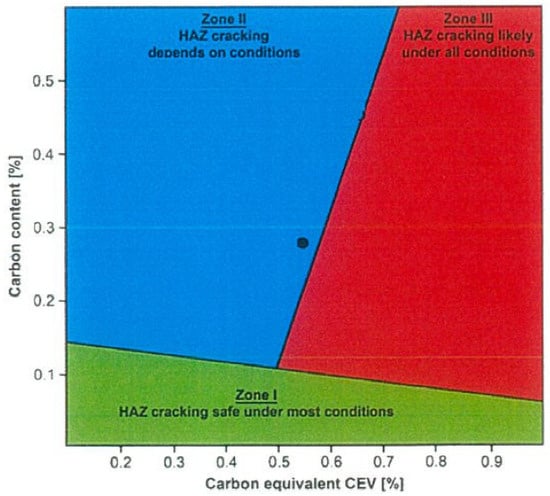
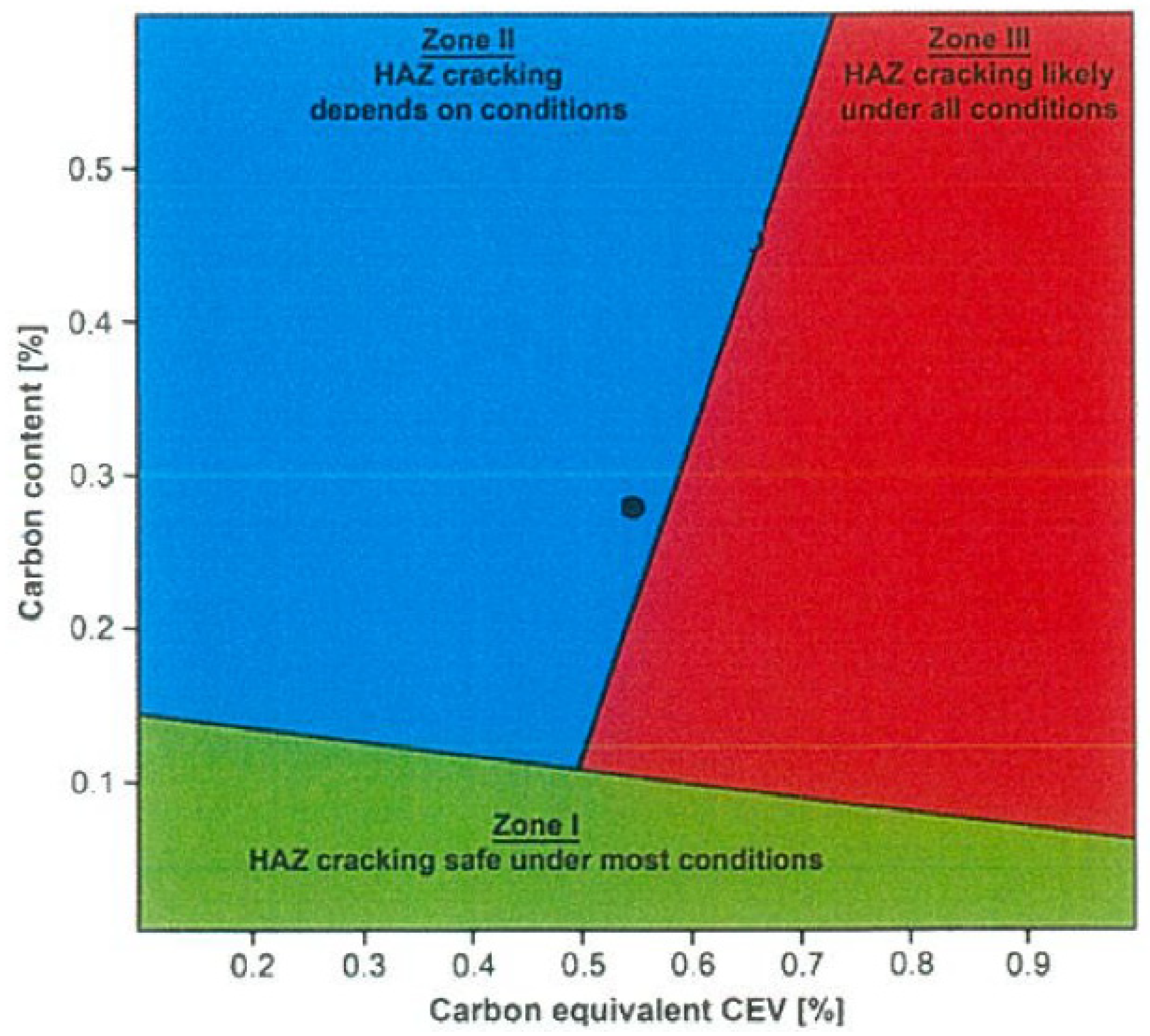
According to the welding heat-affected zone cracking tendency chart recommended by the IIW, as shown in Figure 17, the cracking of the heat-affected zone is related to the carbon content and carbon equivalent of the material. The carbon content of the reducer is 0.39%, and the CEV is 0.808%, so the heat-affected zone of the reducer is in a crack-prone area.
Figure 17.
Crack diagram of the heat-affected zone during welding.
- (2)
- Heat treatment process for welds
The on-site weld heat treatment record shows that the 20G heat treatment process was used. Combined with the good weld quality on the straight pipe side, it can be concluded that the heating rate, heat treatment temperature, isothermal time, and cooling rate of the weld heat treatment on the straight pipe side all meet the requirements of SY/T 4083-2012. However, the C and Cr elements in the reducer exceed the 20G composition standard. Furthermore, the analysis results in (1) indicate that the reducer is more difficult to weld than the 20G process. Therefore, it can be reasonably inferred that the 20G weld heat treatment process cannot meet the requirements for heat treatment of the reducer side weld. Based on the hardness test results of the reducer circumferential weld, base material, and heat-affected zone, the hardness of the heat-affected zone of the reducer exceeds the standard, resulting in a decrease in the crack resistance toughness of the heat-affected zone.
In summary, the cracks in the circumferential welds on the reducer side are brittle fractures. The main reason is that the reducer material does not meet the requirements of 20G, has poor weldability, and the 20G weld heat treatment process is incompatible with the welding requirements of the reducer side. This leads to excessive hardness in the heat-affected zone of the reducer circumferential weld, reduced crack resistance and toughness, and it becomes a weak point in the pipeline during service, eventually cracking and failing under internal pressure.
11. Conclusions and Recommendations
- (1)
- The materials (C and Cr) of the reducer do not meet the requirements for 20G. The hardness of the heat-affected zone (HAZ) welded between the reducer’s small end and the straight pipe does not meet the requirements. The material, impact performance, and hardness of the straight pipe all meet the requirements. No abnormalities were found in the non-metallic inclusions and grain size of the metallographic structure of the straight pipe and reducer.
- (2)
- The main reason for the cracking of the circumferential weld of the reducer is that the material is not 20G (design requirement), resulting in poor weldability, which leads to excessive hardness in the HAZ of the circumferential weld, decreased crack resistance toughness, and failure of the circumferential weld under internal pressure.
- (3)
- It is recommended to re-test the chemical composition of the reducers in use and in stock using a portable elemental analyzer to ensure that the material meets the design standards. Those that do not meet the requirements should be replaced.
- (4)
- It is recommended to strengthen the quality management of pipe fittings supply, do a good job in on-site construction supervision, supervise the construction party to do a good job in weld hardness testing and record it truthfully during the welding process, and ensure that the weld quality meets the requirements.
- (5)
- Specifying a maximum carbon equivalent (CEV) limit for reducers in procurement specifications and enhancing incoming inspection; optimizing Welding Procedure Specifications (WPS) to enforce stricter preheating and Post Weld Heat Treatment (PWHT) controls for high CEV materials; and employing non-destructive testing methods with higher sensitivity for in-service inspection of complex stress areas like reducers.
Author Contributions
Conceptualization, K.X.; methodology, K.X.; software, K.X.; validation, P.W., S.W. and B.W.; formal analysis, K.X.; investigation, S.X.; resources, P.W.; data curation, P.W.; writing—original draft preparation, K.X.; writing—review and editing, B.W.; visualization, K.X.; supervision, B.W.; project administration, B.W.; funding acquisition, B.W. All authors have read and agreed to the published version of the manuscript.
Funding
This research was funded by National Key R&D Program of China grant number [2024YFF0619600] And The APC was funded by China National Petroleum Corporation Forward-looking Basic Research Project, Project No. 2025DJ106.
Data Availability Statement
The datasets presented in this article are not readily available because no new data were created or analyzed in this study. Requests to access the datasets should be directed to the corresponding author.
Acknowledgments
This work was financially supported by the National Key Research and Development Program of China (Grant No. 2024YFF0619600),and by the China National Petroleum Corporation Forward-looking Basic Research Project, Project No. 2025DJ106 for which the authors are deeply grateful. We will acknowledge them in the Acknowledgments section of the paper.
Conflicts of Interest
Author Peng Wang is employed by the company Tarim Oilfield Company of CNPC. The remaining authors declare that the research was conducted in the absence of any potential or financial relationships that could be construed as a potential conflict of interest.
References
- Mokhatab, S.; Poe, W.A.; Mak, J.Y. Handbook of Natural Gas Transmission and Processing: Principles and Practices; Gulf Professional Publishing: Waltham, MA, USA, 2018. [Google Scholar]
- Cosham, A.; Hopkins, P. The assessment of corrosion in pipelines–Guidance in the pipeline defect assessment manual (PDAM). In Proceedings of the Pipeline Pigging and Integrity Management Conference, Amsterdam, The Netherlands, 17–18 May 2004; pp. 17–18. [Google Scholar]
- Meresht, E.S.; Farahani, T.S.; Neshati, J. Failure analysis of stress corrosion cracking occurred in a gas transmission steel pipeline. Eng. Fail. Anal. 2011, 18, 963–970. [Google Scholar] [CrossRef] [Scilit]
- Cao, Y.; Chang, Q.; Zhen, Y. Numerical simulation of fracture behavior for the pipeline with girth weld under axial load. Eng. Fail. Anal. 2022, 136, 106221. [Google Scholar] [CrossRef] [Scilit]
- Zhang, N.; Deng, C.; Lin, Z.; Wang, Z.; Wu, S. The Effect of Misalignment on Stress Concentration and Fatigue Life for Circumferential Weld Joints of Pipeline. Metals 2024, 14, 545. [Google Scholar] [CrossRef] [Scilit]
- Hitter, J.S.; Hitter, M.M.L.; Stafford, S. Failure Analysis of a Welded Block Valve and Reducer. J. Fail. Anal. Prev. 2024, 24, 2714–2724. [Google Scholar] [CrossRef] [Scilit]
- Gbagba, S.; Maccioni, L.; Concli, F. Advances in machine learning techniques used in fatigue life prediction of welded structures. Appl. Sci. 2023, 14, 398. [Google Scholar] [CrossRef] [Scilit]
- Zou, X. Machine Learning in Stress Corrosion Crack Characterisation from Full Matrix Capture Ultrasonic Signal. Ph.D. Thesis, Loughborough University, Loughborough, UK, 2022. [Google Scholar]
- Sudarno, S.; Do, Q.T.; Nubli, H.; Prabowoputra, D.M.; Agusti, N.C.; Ridwan, R.; Vandika, A. Evaluating the influence of environmental factors and parameters on advancements in welding and joining processes: A review. Mek. Maj. Ilm. Mek. 2023, 22, 88–100. [Google Scholar] [CrossRef] [Scilit]
- Zondi, M.C. Factors that affect welding-induced residual stress and distortions in pressure vessel steels and their mitigation techniques: A review. J. Press. Vessel Technol. 2014, 136, 040801. [Google Scholar] [CrossRef] [Scilit]
- Shang, F.; Cai, D.; Sun, B.; Han, Y.; Yang, M.; Zhan, C. Research on weld seam feature extraction and defect identification technology. Nondestruct. Test. Eval. 2025, 40, 3339–3376. [Google Scholar] [CrossRef] [Scilit]
- Perdomo, J.J.; Ganhao, L.A. Failures related to welding. In Analysis and Prevention of Component and Equipment Failures; ASM International: Almere, The Netherlands, 2021; pp. 266–306. [Google Scholar]
- Faghihi, D.; Sarkar, S.; Naderi, M.; Rankin, J.E.; Hackel, L.; Iyyer, N. A probabilistic design method for fatigue life of metallic component. ASCE-ASME J. Risk Uncertain. Eng. Syst. Part B Mech. Eng. 2018, 4, 031005. [Google Scholar] [CrossRef] [Scilit]
- Lassen, T. Risk based fatigue inspection planning—State of the art. Procedia Eng. 2013, 66, 489–499. [Google Scholar] [CrossRef] [Scilit]
- Fragiel, A.; Serna, S.; Malo-Tamayo, J.; Silva, P.; Campill, B.; Martínez-Martínez, E.; Cota, L.; Staia, M.H.; Puchi-Cabrera, E.S.; Perez, R. Effect of microstructure and temperature on the stress corrosion cracking of two microalloyed pipeline steels in H2S environment for gas transport. Eng. Fail. Anal. 2019, 105, 1055–1068. [Google Scholar] [CrossRef] [Scilit]
- Guo, R.; Hu, H.; Zhao, H.; Zhang, Y. Stress Concentration Factors Due to Misalignment at Girth Welds in Bi-Layer Pipes. J. Mar. Sci. Eng. 2024, 12, 231. [Google Scholar] [CrossRef] [Scilit]
- Sun, Y.; Yu, S.; Wang, B.; Gu, T. Numerical Analysis and Optimization of Residual Stress Distribution in Lined Pipe Overlay Welding. Processes 2025, 13, 1548. [Google Scholar] [CrossRef] [Scilit]
- Arora, H.; Kumar, R.; Gulati, P.; Sharma, S.; Dwivedi, S.P.; Saxena, A.; Kumar, A.; Sharma, K.; Kozak, D.; Hunjet, A.; et al. Numerical simulation of temperature distribution and residual stress in TIG welding of stainless-steel single-pass flange butt joint using finite element analysis. High Temp. Mater. Process. 2024, 43, 20240015. [Google Scholar] [CrossRef] [Scilit]


Disclaimer/Publisher’s Note: The statements, opinions and data contained in all publications are solely those of the individual author(s) and contributor(s) and not of MDPI and/or the editor(s). MDPI and/or the editor(s) disclaim responsibility for any injury to people or property resulting from any ideas, methods, instructions or products referred to in the content. |
© 2026 by the authors. Licensee MDPI, Basel, Switzerland. This article is an open access article distributed under the terms and conditions of the Creative Commons Attribution (CC BY) license.