


Abstract
Rack railway systems operating on steep-gradient routes rely on rack-and-pinion propulsion mechanisms that generate substantial vibrational excitation through cyclic gear mesh contact, adversely affecting passenger comfort and long-term mechanical reliability. Conventional integrated steel gears transmit propulsive forces without inherent vibration attenuation, and a systematic design methodology for optimising the internal rubber spring configuration of elastic gears for such applications has not been established. This study develops a kinematic spring-mass model for both conventional steel and elastic rubber gear configurations in a Korean rack railway propulsion system and validates it through controlled experimental testing. A high-speed rail–wheel contact simulator was employed to measure vertical vibrational accelerations under rigid–rigid (steel–steel) and rigid–resilient (steel–rubber elastic gear) contact conditions, with a load simulating steep-gradient operational forces applied to the gear assembly. The elastic gear achieved a 25.1-fold reduction in vertical vibrational acceleration relative to the steel gear baseline (6.4 m/s2 vs. 160.7 m/s2). Time-domain statistics (mean, RMS, standard deviation and peak envelope) are reported for both configurations from repeated runs. Analysis of the normalised effective stiffness as a function of the number of rubber springs predicts that four springs represent a practical optimum, beyond which the incremental stiffness change falls below 0.5%; experimental validation of intermediate spring counts is identified as future work. A spring-number optimisation framework is proposed that returns both a spring count and a rubber compound specification, balancing vibration attenuation against load distribution, torque-transmission capacity and component fatigue life.
1. Introduction
Rack railways, also referred to as rack-and-pinion or cog railways, employ a toothed rack rail installed at the centre of the track to generate propulsive force through engagement with a pinion gear mounted on the vehicle bogie. This configuration enables operation on steep-gradient routes exceeding 180‰, where adhesion-based traction alone cannot maintain controlled propulsion. As mountain and tourist railway networks expand into challenging terrain, the demand for rack propulsion systems that are simultaneously reliable, durable, and comfortable for passengers has grown accordingly. Recent experimental work on rack railway track systems has shown that the impulsive forces produced at the rack–pinion engagement propagate through the rails, sleepers, and ballast, and that the traction load strongly governs both rack–tooth bending stress and wheel–rail contact forces [1].
A fundamental challenge in rack railway operation is the vibration and noise generated by the periodic engagement of the rack and pinion teeth. In gear systems this excitation originates primarily from transmission error—the deviation from ideally uniform motion transfer caused by tooth-profile tolerances, elastic deflection under load, and the time-varying number of tooth pairs in contact, which produces a periodically fluctuating mesh stiffness [2]. The comprehensive review of gear-dynamic models by Ozguven and Houser [2] identified time-varying mesh stiffness and tooth error as the dominant internal sources of dynamic excitation, while the nonlinear analysis of Kahraman and Singh [3] showed that backlash and parametric stiffness variation can drive large-amplitude, jump-type responses. In rack railways these mechanisms are aggravated by the high propulsive loads required to climb steep gradients, which amplify the dynamic forces at the mesh interface; the resulting vibration degrades passenger comfort and accelerates fatigue in gear teeth, bearings, and bogie structures, raising maintenance cost and reducing availability.
A range of analytical models has been developed to characterise this behaviour. Yang and Sun [4] proposed a rotary dynamic model for spur gears that established the foundational coupling between tooth stiffness and vibrational response under meshing. Abbes et al. [5] extended this through an elastic-foundation formulation capturing the influence of tooth defects on mesh stiffness and the resulting vibration, while a companion acoustic–structural interaction model [6] linked the effective stiffness of the tooth contact to gearbox-radiated noise. A consistent conclusion across these studies is that the effective stiffness of the gear-contact path is the primary determinant of dynamic excitation, and that deliberately introducing compliance into this path is therefore an effective route to vibration attenuation.
Introducing compliance through elastomeric elements is already well established at the driveline level. Highly flexible rubber couplings—exemplified by commercial designs such as those of Falk, Voith, and Centa—are routinely fitted between rotating shafts to lower torsional stiffness, accommodate misalignment, and damp torque fluctuations. Such couplings, however, act on the shaft assembly as a whole and are located away from the tooth-contact interface; they neither suppress the excitation generated within the rack–pinion mesh itself nor satisfy the compact, high-load geometry of a rack railway pinion. A double-layered elastic gear, in which rubber springs are embedded directly between an inner and an outer gear ring, instead places the compliant element within the transmission path at the mesh, allowing the gear to retain its loadbearing tooth geometry while attenuating vibration at its source.
Designing such a gear is complicated by the mechanical behaviour of rubber, which is nonlinear, rate- and temperature-dependent, hysteretic, and subject to amplitude-dependent dynamic stiffening and to stress softening under cyclic loading. Green and English [7] demonstrated the strongly nonlinear compressive response of confined elastomeric components, underscoring the difficulty of assigning a single representative stiffness. In railway applications specifically, Gong et al. [8] showed that the dynamic stiffness of rubber elements varies markedly with temperature and excitation frequency—falling ambient temperature substantially increasing stiffness—with direct consequences for predicted car-body vibration. These effects make the in situ stiffness of a rubber spring embedded in an assembled gear difficult to measure or predict a priori, motivating an experimentally grounded, data-based approach.
Despite the recognised benefits of rubber-damped gears, a systematic methodology for determining the optimal number and arrangement of rubber springs within an assembled elastic gear has not been reported, particularly for rack railway propulsion. Existing studies address either gear dynamics with rigid teeth or elastomeric compliance at the coupling level, but not the design of the compliant gear itself. The present study addresses this gap by developing a kinematic spring model for a double-layered elastic gear designed for a Korean rack railway propulsion system and by deriving the effective stiffness directly from measured vibrational acceleration, thereby circumventing the difficulty of in situ stiffness measurement. The specific objectives are: (i) to derive analytical expressions for the effective spring constant of the elastic gear as a function of the number of internal rubber springs; (ii) to validate the vibration-attenuation performance of the elastic gear experimentally using a rail–wheel contact simulator; and (iii) to propose an optimisation framework that identifies the minimum number of rubber springs required to achieve the target reduction in vibrational acceleration while satisfying load-distribution and fatigue constraints. The outcomes provide practical design guidelines for elastic gear development and contribute to improved passenger comfort and operational reliability in mountain railway systems.
The contribution of this study is stated explicitly and hierarchically. The primary contribution is the spring-number optimisation process: a reproducible design procedure that links a single sub-unit prototype measurement to an optimised internal spring count for a double-layered elastic gear, without requiring direct in situ stiffness measurement of the assembled rubber elements. The two supporting contributions are the vibration-data-based effective stiffness estimation method, and the application of the double-layered elastic gear architecture to rack-and-pinion propulsion under steep-gradient loads, which to the authors’ knowledge has not previously been reported for rack railway systems. Although elastomeric bushings are widely used for vibration attenuation in the automotive field, the structural configuration and load paths of railway rack-and-pinion propulsion differ substantially, so a dedicated design methodology is required.
A further outcome of the procedure, developed in Section 4, is that the identified stiffness constitutes a design specification for the rubber path which may be satisfied either by element geometry or by compound selection. The method therefore returns not only the number of springs but also the material requirement, and can be used to guide the selection of the rubber type.
The dynamic behaviour of the rack railway system as a whole has been characterised in a parallel body of the railway-engineering literature that is directly relevant to the present component study. Coupled vehicle–track models of rack vehicles on large-slope lines have been developed and validated experimentally [9], and extended to represent the flexibility of the rack structure under gear-rack mesh impact [10]. Multibody formulations of gear-rack meshing dynamics have quantified the mesh forces generated in rack rail vehicles [11], while wayside vibration measurement has been established as a practical means of diagnosing vehicle dynamic behaviour from acceleration signals [12]. These studies describe the excitation environment into which the present elastic gear is introduced and provide the vehicle-level context against which component-level results must ultimately be interpreted.
2. Materials and Methods
2.1. Design of the Elastic Gear for the Rack Railway
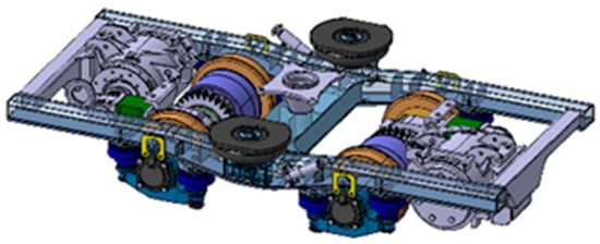
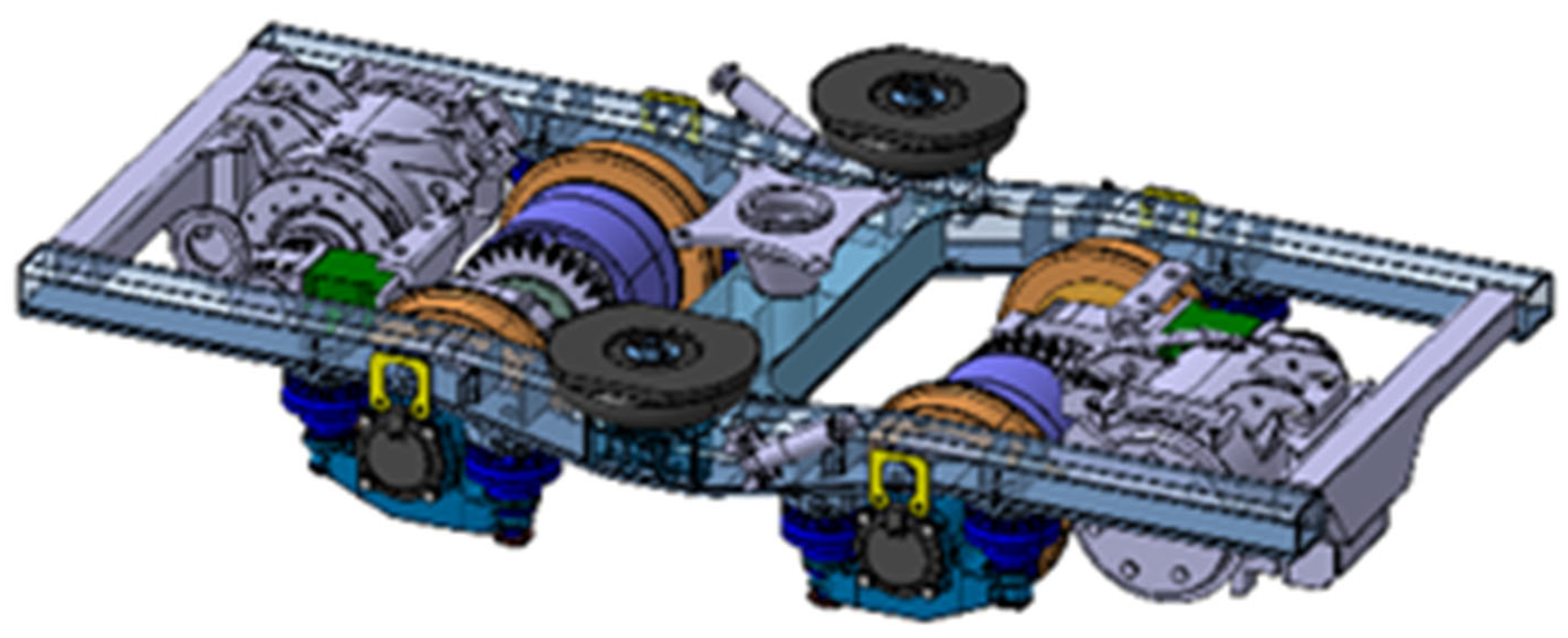
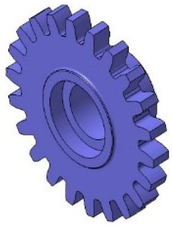
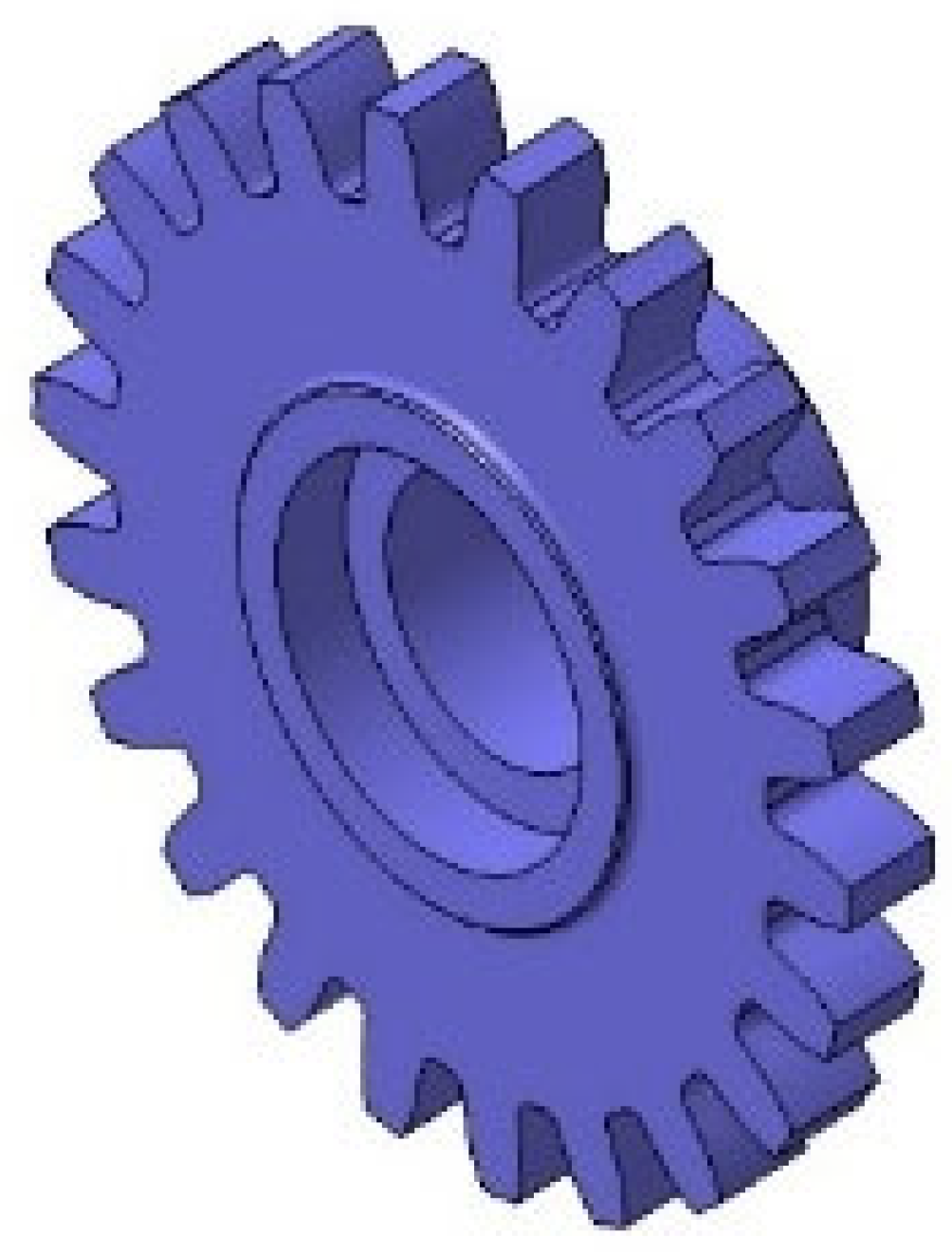
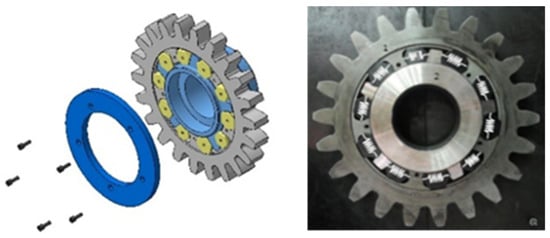
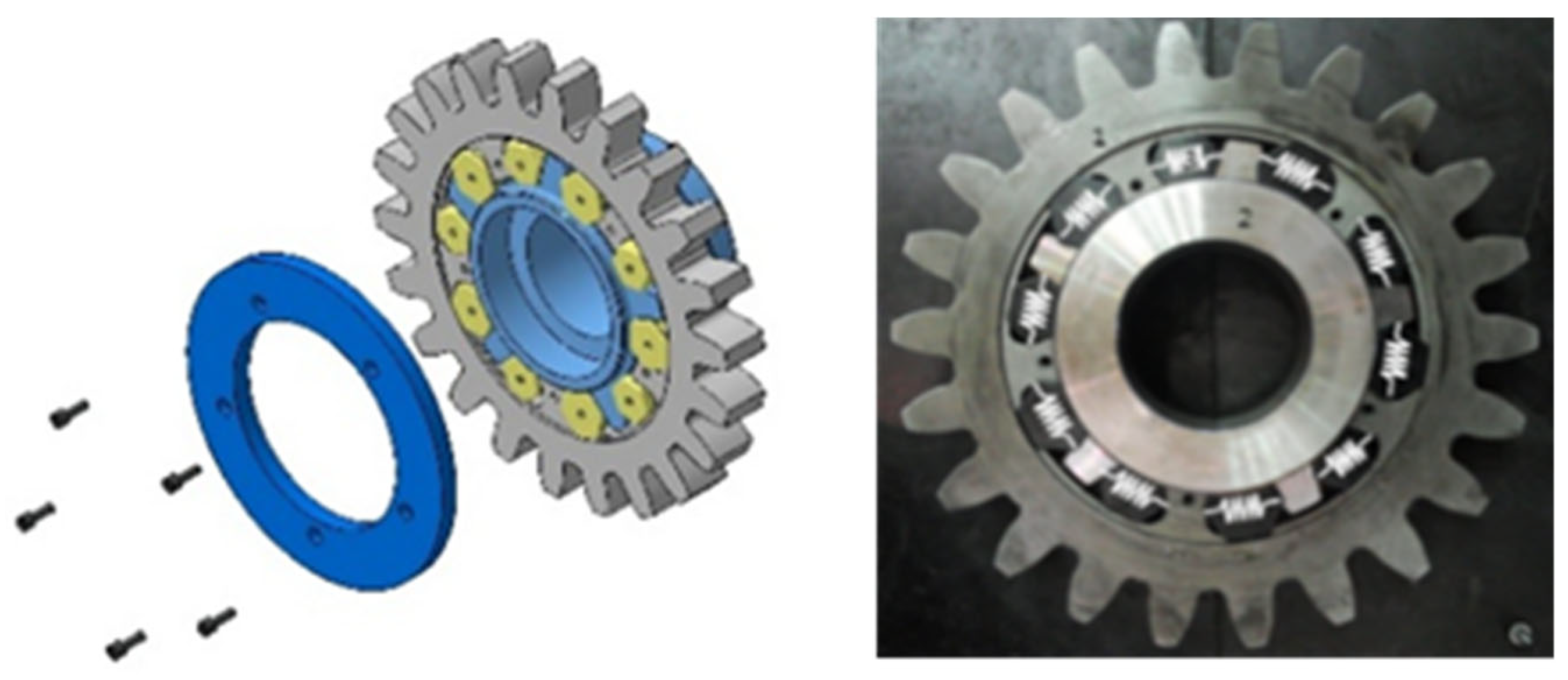
Rack railway propulsion systems experience vibration and noise due to the cyclic meshing of the rack and pinion. To mitigate these effects, a double-layered elastic gear was designed in which rubber springs are inserted between an outer pinion and an inner pinion, replacing the conventional single-piece integrated steel gear (Figure 1 and Figure 2). In the initial prototype, ten rubber springs were installed between the gear layers (Figure 3). This configuration allows the elastic gear to attenuate vibrational energy transmitted from the rack–pinion contact before it propagates into the bogie frame and vehicle body. The rubber springs are arranged in a parallel configuration between the inner and outer pinion, enabling load sharing and providing a means to tune the overall system stiffness by varying the number of springs. The rubber springs were purpose-fabricated for this application from the elastomer grade used for railway-vehicle bushings. The complete geometric and material specification of the pinion, the rack and the rubber springs is given in Table 1, together with the operating conditions of the test. The principal gear dimensions follow directly from the test operating point: the pinion carries Z = 22 teeth and rotates at N = 240 rpm, which corresponds to a vehicle speed of approximately 20 km/h, so the pitch-line velocity gives a pitch circumference of v/N = 1.389 m and hence a pitch diameter of d = 440 mm, a pitch radius of rp = 220 mm, and a module of mn = d/Z = 20 mm, which is a standard module for rack railway pinions. The gear-mesh frequency at this operating point is fm = Z N/60 = 88 Hz.
Figure 1.
Trailer bogie of the rack railway system showing the gear-propelled propulsion configuration.
Figure 2.
Conventional single-piece integrated steel gear.
Figure 3.
Double-layered elastic rubber gear prototype with ten internal rubber springs.
Table 1.
Specification of the pinion, rack, rubber springs and test operating conditions.
2.2. Dynamic Modelling of the Conventional Gear System
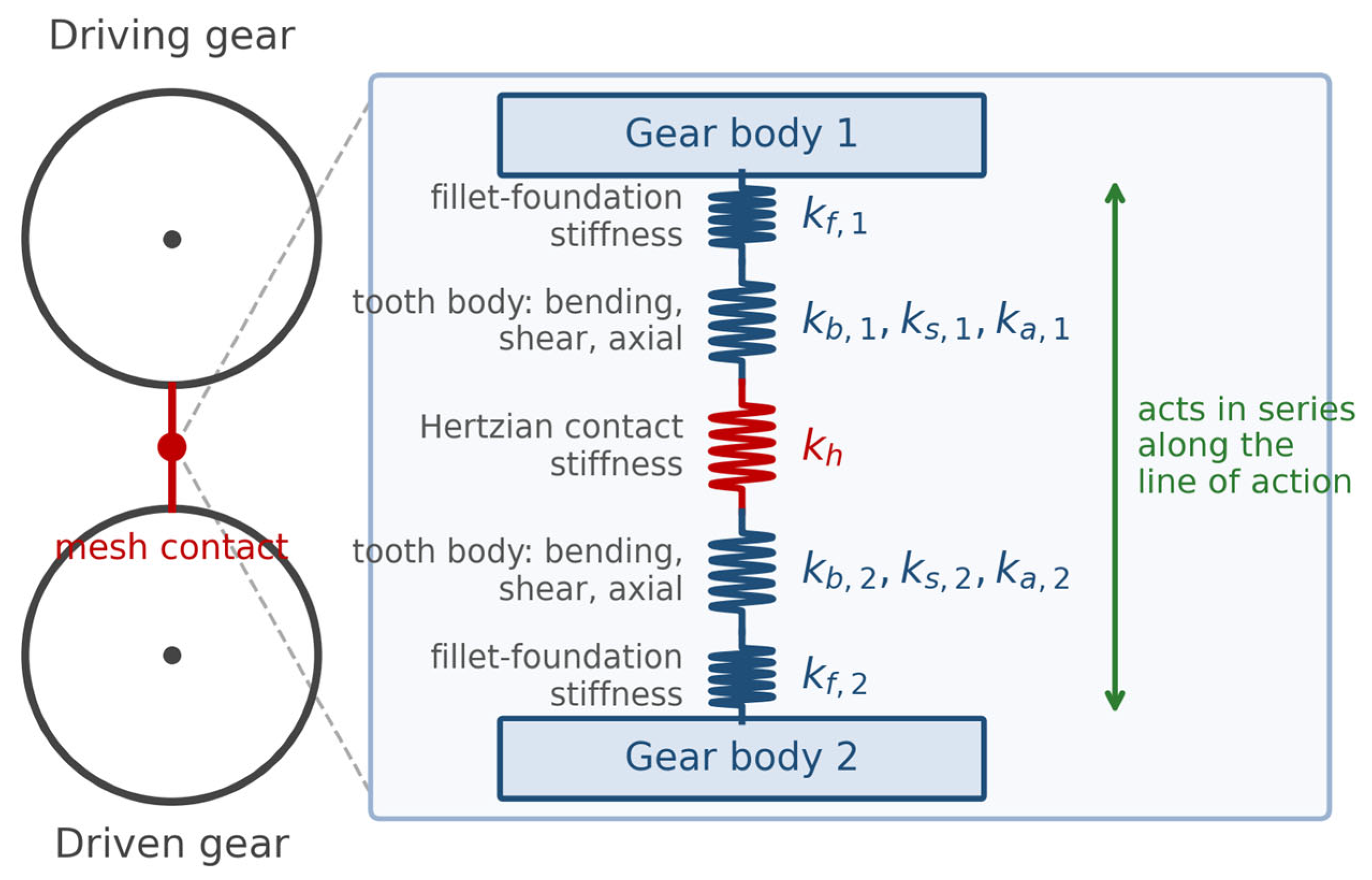
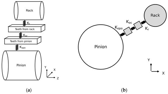
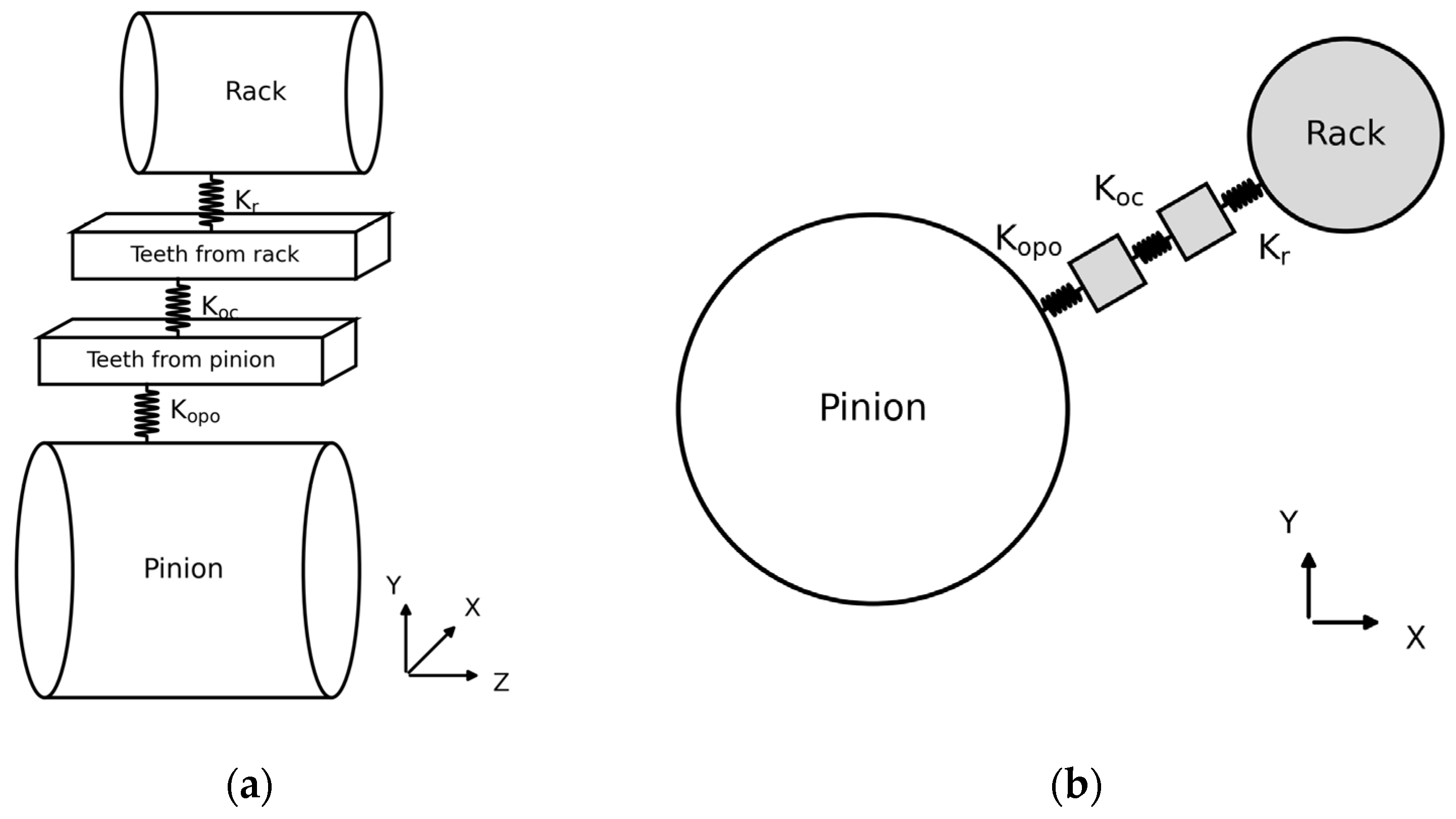
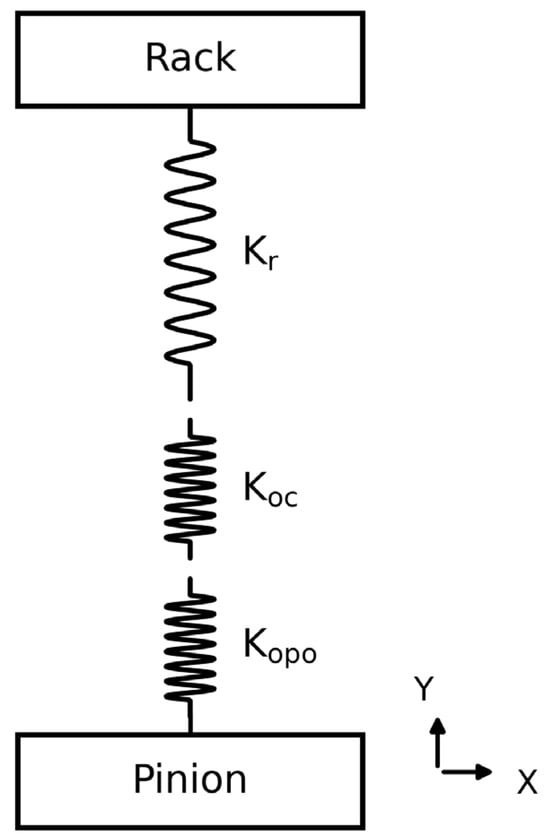
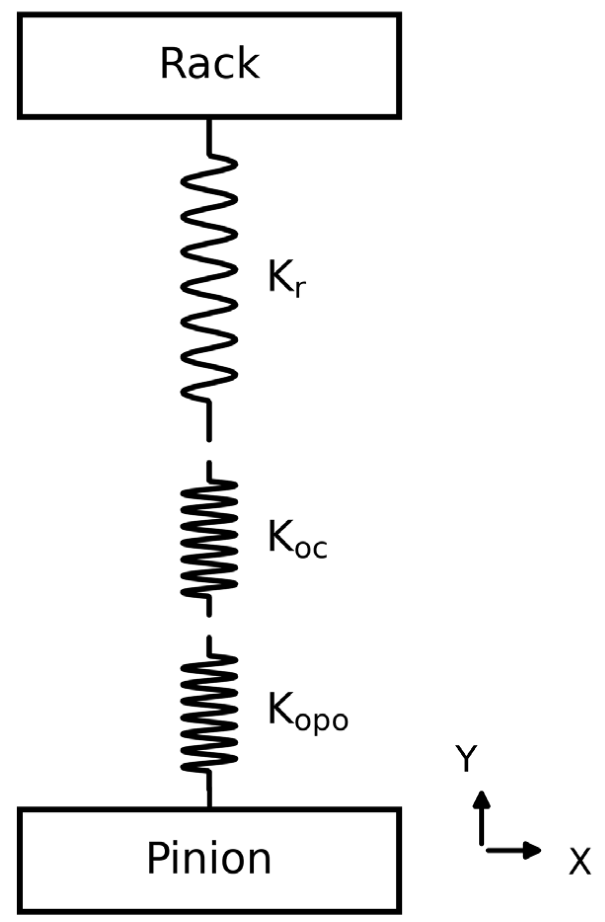
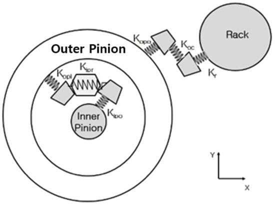
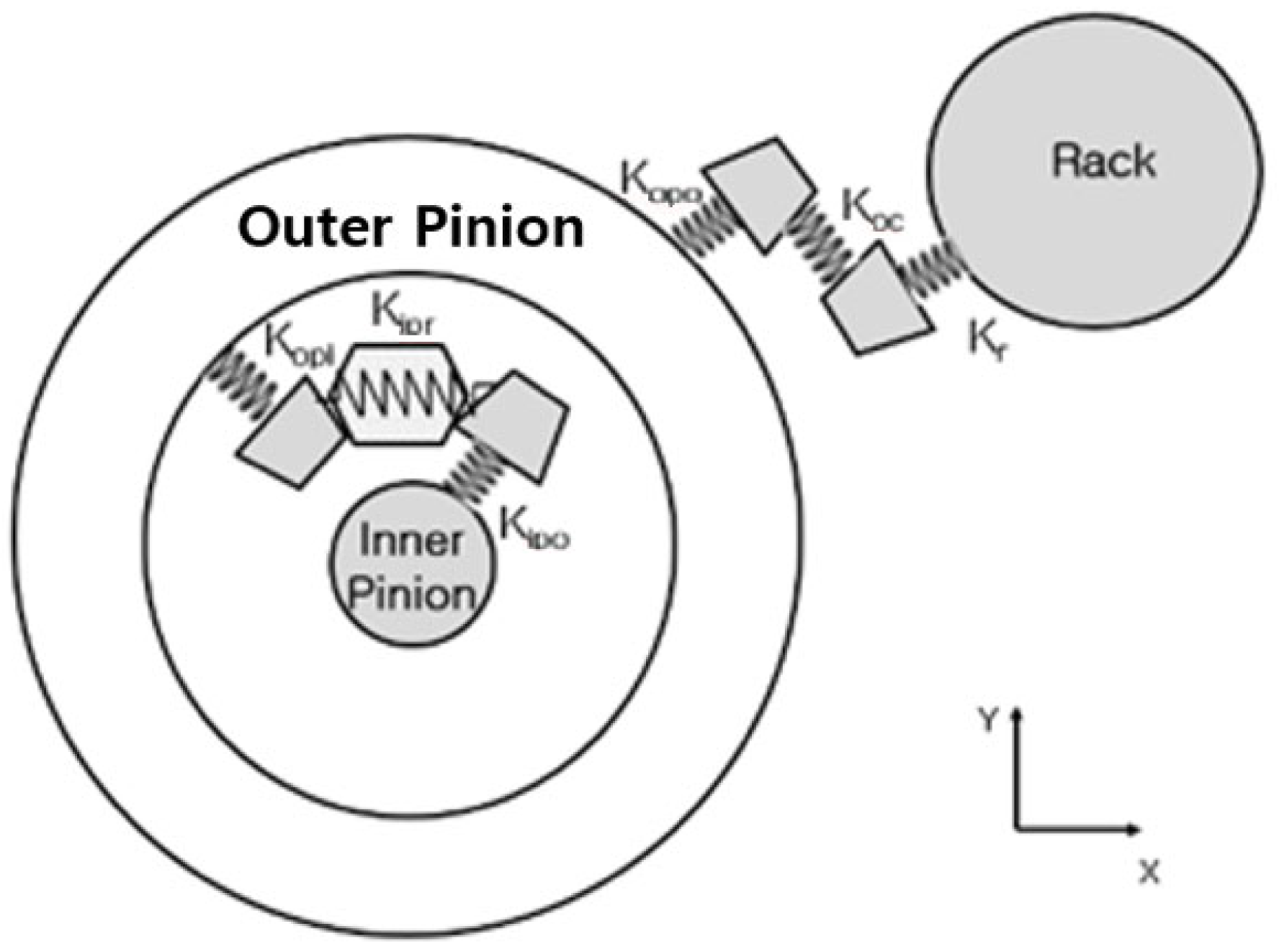
Vibration in the rack railway propulsion system arises from the periodic contact between the rack and pinion teeth. Based on the kinematic model proposed by Abbes et al. [2], in which gear tooth contacts are represented as spring elements without damping (Figure 4), a simplified model of the steel gear system was developed (Figure 5). Following the potential-energy formulation of gear mesh stiffness established by Yang and Sun [4] and developed subsequently [13,14], the compliance of a loaded tooth pair is represented by elements acting in series along the line of action. Three spring elements represent the contact compliance in the present model: Kr, the fillet-foundation stiffness representing elastic deflection of the gear body and root fillet beneath the loaded tooth (denoted kf in the standard formulation [14]); Koc, the Hertzian contact stiffness representing local elastic deformation at the contact interface (kh); and Kopo, the tooth body stiffness, defined as the series combination of the bending, shear and axial compressive compliances of the tooth treated as a tapered cantilever loaded at the contact point (kb, ks and ka). These three elements act in series along the line of action, as illustrated in Figure 6. The equivalent series spring constant for the conventional steel gear system is expressed as Equation (1):
Figure 4.
Kinematic model of a general gear system, showing the compliance elements of a meshing tooth pair acting in series along the line of action (adapted from Abbes et al. [2]; notation follows the potential-energy decomposition defined in Section 2.2).
Figure 5.
Simplified kinematic model of a conventional steel gear set: (a) isometric view; (b) side view.
Figure 6.
Physical model of the rack-and-pinion contact showing the series arrangement of spring elements Kr, Koc, and Kopo.
The contact surface stiffness Koc is derived from Hertzian contact theory [3]:
where E is the elastic modulus of the gear material (GPa), b is the contact width (m), and ν is the Poisson’s ratio of the gear material (dimensionless).
The role of Equations (1)–(4) in this study requires clarification. They establish the topology of the stiffness network—that the tooth-contact elements act in series and that the rubber springs act in parallel—and it is this topology, rather than the absolute magnitude of the individual components, that governs the spring-number relation derived in Section 3.3. The individual components are nevertheless evaluated for the test gear so that the model can be checked against measurement: the Hertzian term from Equation (2); the bending, shear and axial terms from the potential-energy integrals over the tooth profile [4,13]; and the fillet-foundation term from the polynomial formulation of Sainsot, Velex and Duverger [14]. The resulting component values, computed from the gear data of Table 1, are compared with the values identified from measurement in Section 3.4.
For the rubber elements, the compression stiffness of a pocketed block is evaluated as K = Ea A/t, where A is the loaded area, t the element thickness and Ea the apparent compression modulus. The apparent modulus is related to the intrinsic Young modulus E0 through the shape factor S of the element by Ea = E0 (1 + 2 k S2), where k is a material constant. This provides a geometry-based estimate of the rubber-path stiffness that is independent of the vibration measurement and is compared with it in Section 3.4.
2.3. Physical and Dynamic Modelling of the Double-Layered Elastic Gear
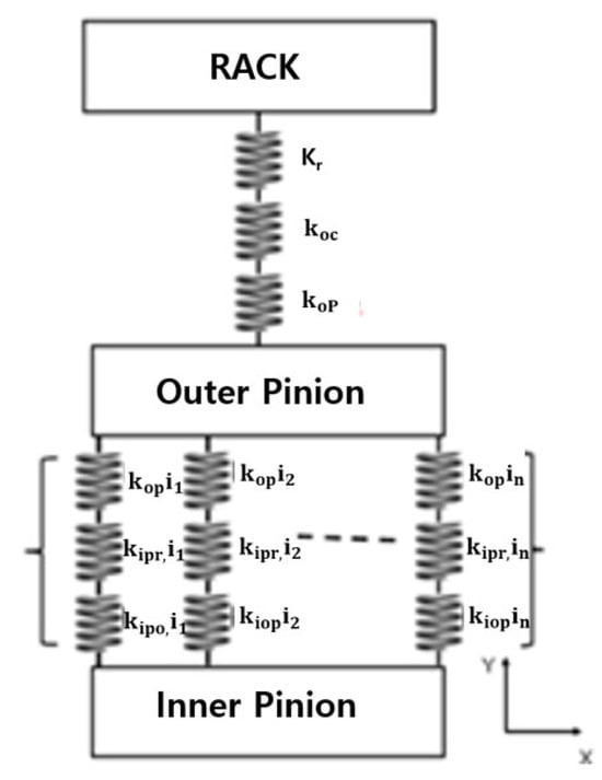
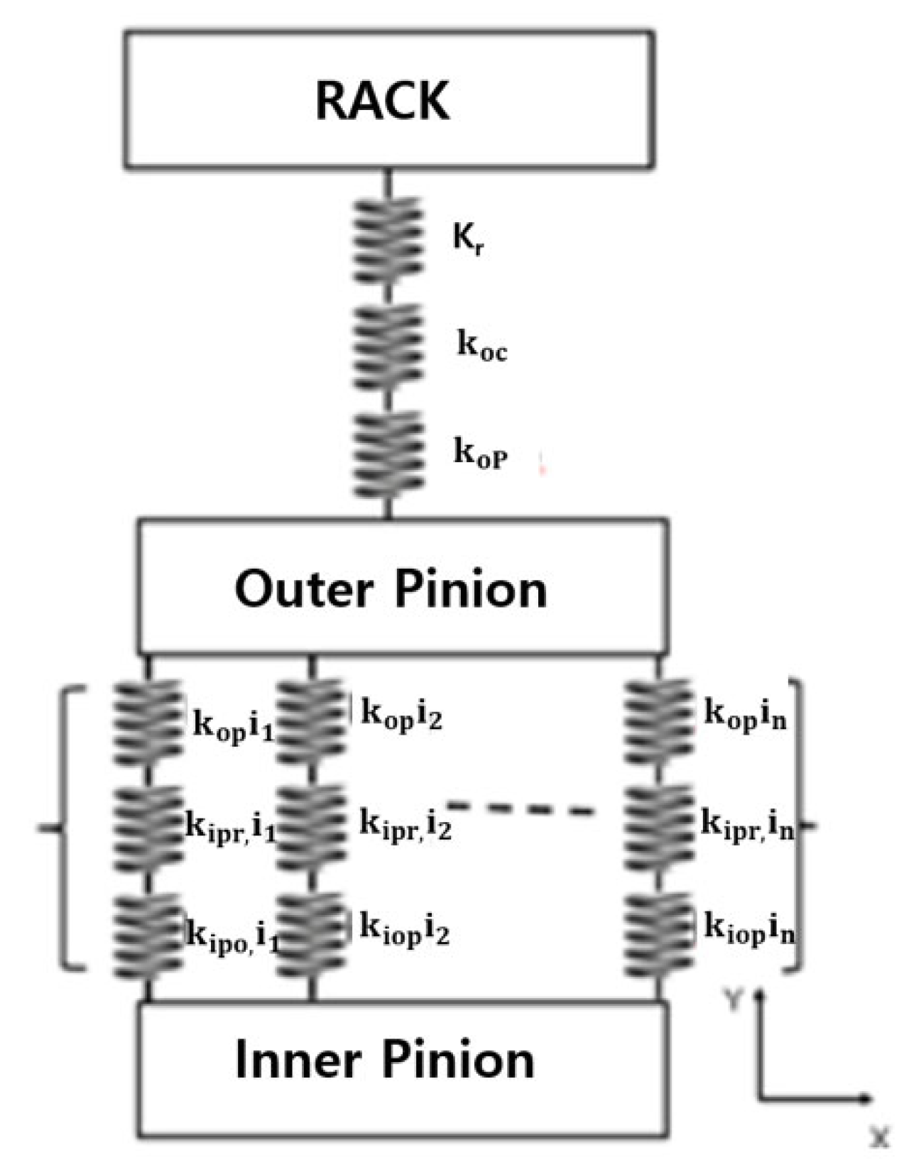
The elastic gear consists of three components: the outer pinion, the inner pinion, and the rack. The rack–outer pinion contact is modelled using the same approach as Section 2.2. The contact between the inner and outer pinion incorporates n rubber springs connected in parallel (Figure 7 and Figure 8).
Figure 7.
Kinematic model of the elastic rubber gear system.
Figure 8.
Physical model of the elastic rubber gear, illustrating the series-parallel spring configuration.
The complete spring model combining the steel gear contact spring and the rubber spring assembly in series is equation below
In Equation (3) the summation runs over the n rubber-spring paths acting in parallel between the inner and outer pinion. Each path i is the series combination of three elements: kop,i, the contact stiffness between the outer pinion and the spring seat; kipr,i, the stiffness of the rubber element itself; and kipo,i, the contact stiffness between the spring seat and the inner pinion. All three carry the same path index i, and no other stiffness terms enter the summation.
2.4. Spring Constant Prediction from Vibrational Acceleration Data
To predict spring constants from measured vibrational acceleration data, the standard mass-spring-damper (MCK) equation of motion was applied:
Rearranging to express acceleration explicitly gives
Following Abbes et al. [2], damping was neglected (c = 0). Substituting into Equation (6):
The stiffness k appearing in Equation (7) is the equivalent stiffness of the complete load path between the rack contact and the measurement point. It is ksteel, given by Equation (1), for the rigid–rigid (steel-steel) configuration, and ktotal, given by Equation (4), for the rigid–resilient (elastic gear) configuration. The configuration-specific subscript is used in Equations (8)–(11) accordingly.
The neglect of damping requires justification, since rubber is a nonlinear viscoelastic material. Under harmonic loading the stress in an elastomer leads the strain by a loss angle, so the dynamic behaviour is properly described by a complex modulus and, correspondingly, by a complex dynamic stiffness k* = k′(1 + i η), in which k′ is the storage stiffness and η the loss factor. Inverting Equation (7) from a measured acceleration amplitude therefore identifies the magnitude of the complex dynamic stiffness, |k*| = k′ (1 + η2)(1/2), rather than the purely elastic stiffness. For the filled elastomer grades used in railway bushing applications, the reported loss factors lie in the range η = 0.05–0.30 [15,16], so the corresponding systematic overestimate of the elastic stiffness is between 0.1% and 4.4%. Because the stiffness difference resolved in this study is 99.6%, an error of this magnitude cannot affect the comparison; and since |k*| is not smaller than k′, the simplification is conservative, in the sense that the true stiffness reduction is at least as large as that reported. The steel–steel contact path has a loss factor smaller by approximately an order of magnitude, so the rigid baseline is essentially unaffected.
Two further assumptions are stated explicitly. First, the model is linearised about the preloaded operating point defined by the applied axle load, the fixed rotational speed and the ambient test temperature, so all identified stiffness quantities are effective operating-point values rather than constitutive material properties. Second, because the vibratory displacement amplitude x at the measurement point was not measured independently, the analysis of Section 3.2 proceeds entirely in dimensionless ratio form, under the assumption that the displacement amplitude is comparable between the two configurations tested under identical excitation. Under this assumption both the displacement amplitude and the effective mass cancel from the ratio, as shown in Section 3.2.
The model is accordingly restricted to the stiffness-controlled, non-resonant regime in which the measurements were taken. Because hysteretic damping is the mechanism that limits response amplification at resonance, an undamped model cannot be used to assess resonance margins; this restriction, and the viscoelastic formulations appropriate to removing it, are discussed in Section 4.
2.5. Test Facility
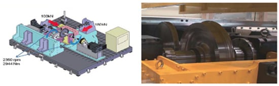
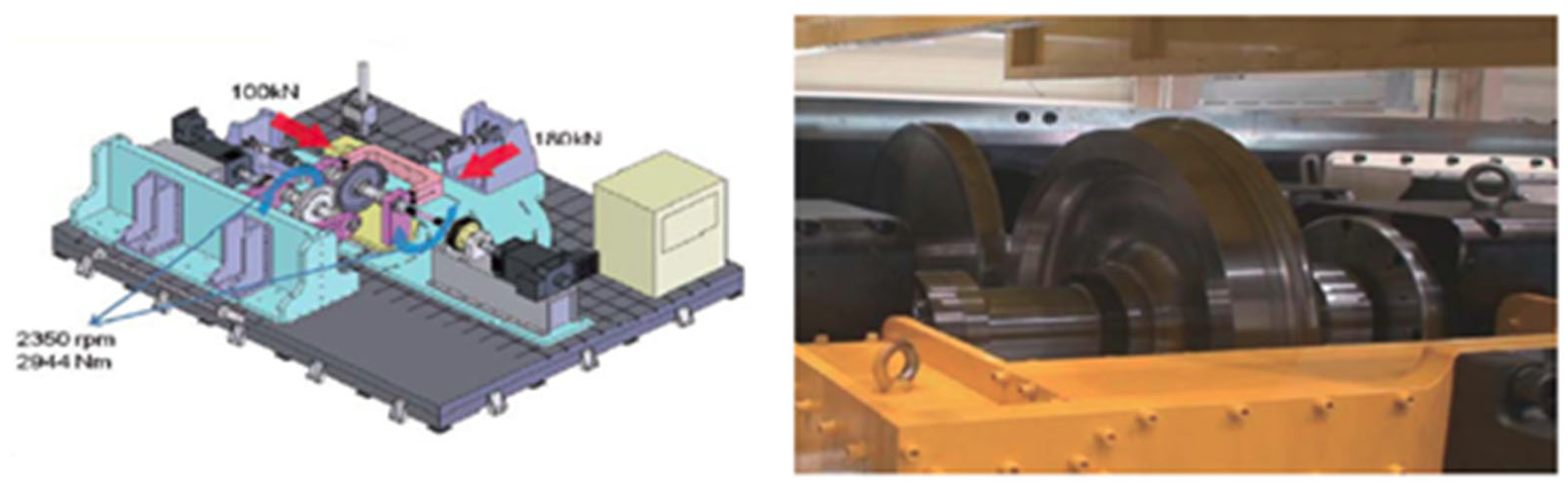
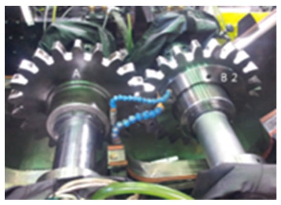
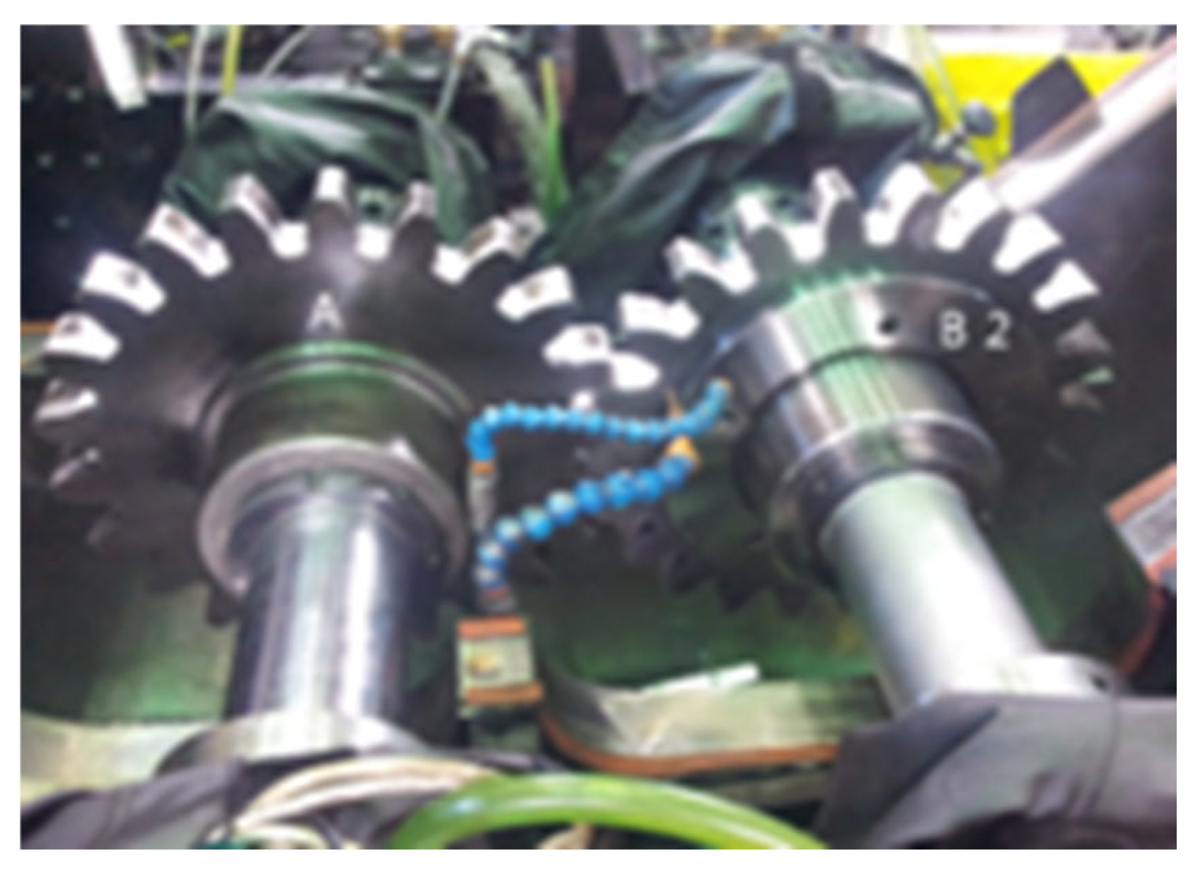
To validate the vibration attenuation performance of the elastic gear, a high-speed rail–wheel contact simulator (Figure 9) was employed. Acceleration signals were acquired from a sensor attached directly to the pinion. The pinion was driven at 240 rpm, corresponding to mountain railway operation at approximately 20 km/h on a steep gradient. The pinion has Z = 22 teeth, so the gear-mesh frequency at the test speed is fm = Z N/60 = 22 × 240/60 = 88 Hz. Acceleration was acquired triaxially using the accelerometer integrated in the simulator at the pinion; in these measurements the two horizontal components were small relative to the vertical component, which dominated the response, and vertical acceleration was therefore adopted as the reported evaluation indicator. This selection is discussed further in Section 4. Testing was carried out at an ambient temperature of approximately 20 °C, and each contact configuration was tested five to six times.
Figure 9.
High-speed rail–wheel contact simulator used for vibration attenuation testing.
2.6. Specimen Configuration and Contact Conditions
Two contact configurations were tested:
- (1)
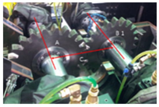
- Rigid-rigid contact: Steel gear meshing with the steel rack (Figure 10)—conventional baseline.Figure 10. Rigid–rigid contact configuration: Steel gear meshing with the steel rack.
- (2)
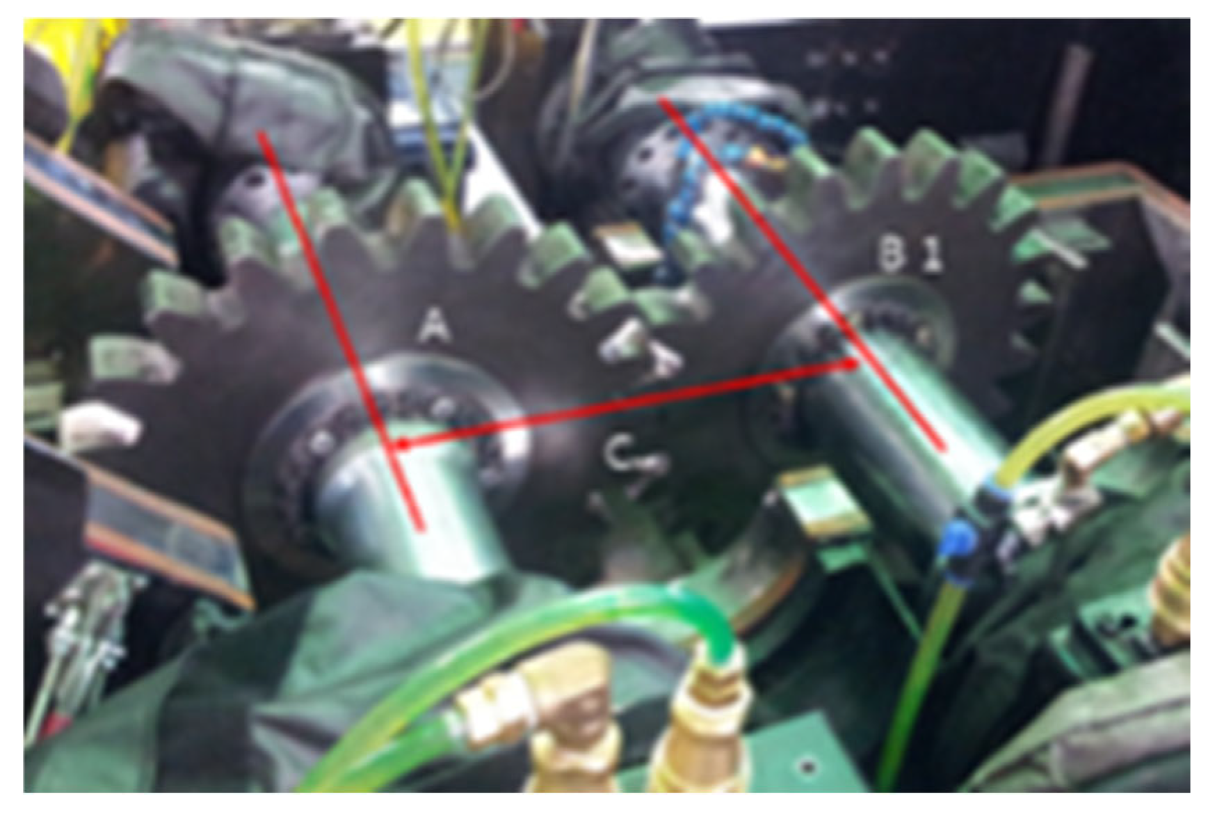
- Rigid–resilient contact: Steel rack meshing with the double-layered elastic gear incorporating rubber springs (Figure 11)—proposed configuration.Figure 11. Rigid–resilient contact configuration: Steel rack meshing with the double-layered elastic gear.
- (3)
- The tests reported here are sub-unit component tests, carried out before the manufacture of a complete mountain-railway vehicle, and their purpose is to compare the two gear configurations under identical and controlled conditions. Track irregularity, rack installation error and vehicle bounce and roll are absent from the test rig by design: these effects are common to both configurations and would introduce variability that would confound precisely the comparison the test is intended to make. Their exclusion at this stage is therefore deliberate, and the consequences for transferability of the results to service conditions are addressed in Section 4.
2.7. Load Application
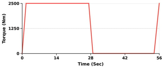
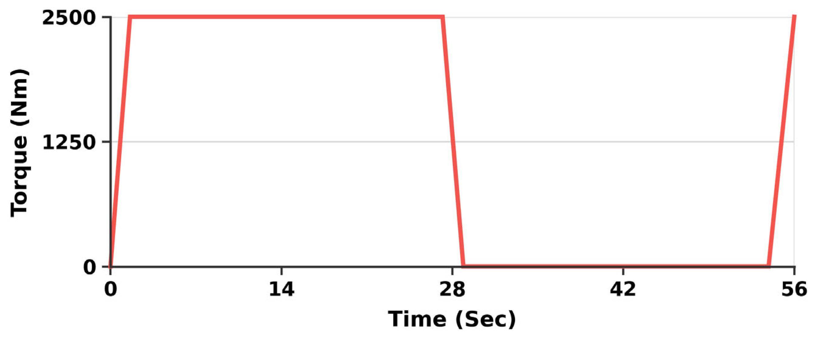
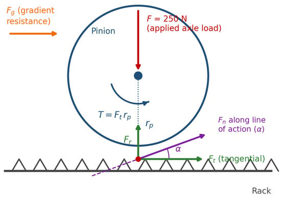
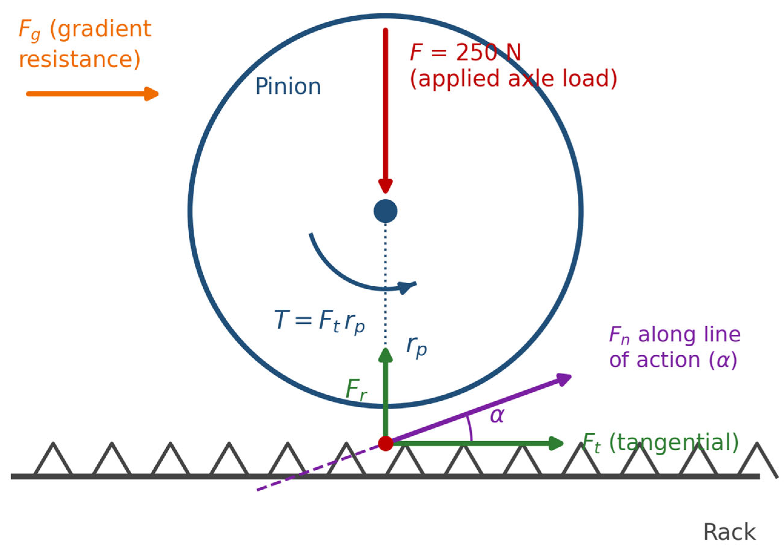
A load of 250 N was applied to the axle at which the pinion was installed (Figure 12), replicating the torque variation on a steep gradient slope; the applied torque record is shown in Figure 12. The corresponding force system at the rack–pinion engagement is shown in Figure 13, which gives the free-body representation of the applied axle load, the normal and tangential mesh force components resolved along and perpendicular to the line of action at the pressure angle, and the gradient-resisting force. The two figures are related by T = Ft rp, where Ft is the tangential mesh force and rp the pitch radius of the pinion. Vertical vibrational acceleration at the gear was measured under both contact configurations under this applied load.
Figure 12.
Time history of the torque applied to the pinion axle during testing.
Figure 13.
Free-body representation of the rack–pinion engagement, showing the applied axle load, the tangential and radial mesh force components, the normal force along the line of action at the pressure angle, and the gradient-resisting force.
3. Results
3.1. Vibration Attenuation Test Results
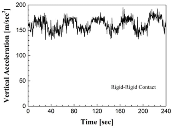
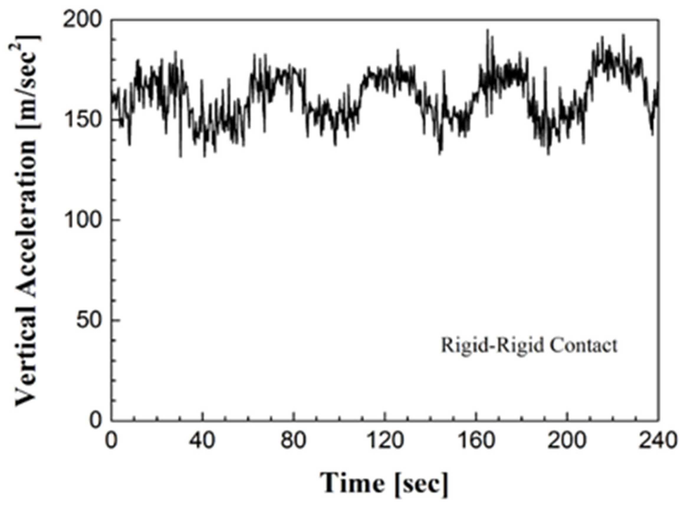
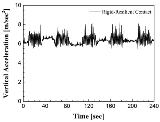
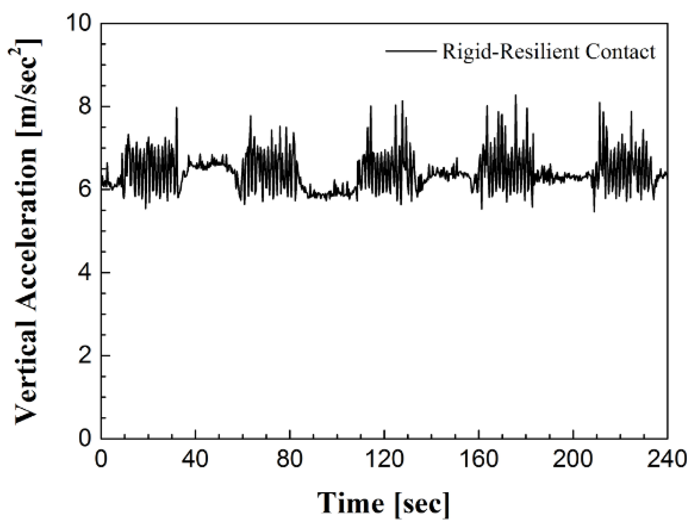
Table 2 summarises the mean vertical vibrational acceleration values recorded for each contact configuration. The vertical vibrational acceleration was reduced from 160.7 m/s2 under rigid–rigid contact to 6.4 m/s2 under rigid–resilient contact with ten rubber springs, corresponding to a vibration attenuation ratio ACCratio of 25.1. Vertical acceleration time histories are shown in Figure 14 and Figure 15.
Table 2.
Vertical vibrational acceleration test results (most conservative of five to six repeated runs per configuration).
Figure 14.
Vertical vibrational acceleration time history for rigid–rigid contact (steel–steel gear).
Figure 15.
Vertical vibrational acceleration time history for rigid–resilient contact (steel–rubber elastic gear).
In addition to the mean values, Table 3 reports time-domain statistics of the recorded histories: the RMS acceleration, the standard deviation of the level fluctuation, and the observed peak envelope. Each contact configuration was tested five to six times; the repeated runs produced closely similar time histories, and the least favourable (most conservative) elastic-gear record is reported, so the quoted attenuation ratio represents a lower bound on the observed performance. Because the archived records do not retain the full measurement bandwidth, a frequency-domain decomposition resolving the gear-mesh frequency of 88 Hz (Section 2.5) cannot be reproduced from them; spectral characterisation is accordingly identified as future work in Section 4.
Table 3.
Time-domain statistics of the recorded vertical acceleration histories.
3.2. Spring Constant Prediction
3.2.1. Spring Constant for Rigid–Rigid Contact
Using Equation (7), the spring constant of the steel gear in the vertical direction was determined via Equations (8) and (9):
From Equation (8), the amplitude of the restoring force acting on the effective mass is ACCsteel m = 160.7 × 25.5 = 4099 N, where the effective mass m = 25.5 kg follows from the applied axle load F = 250 N via m = F/g = 250/9.8 = 25.5 kg.
Because the vibratory displacement amplitude xsteel at the measurement point was not measured independently, ksteel is not evaluated in absolute units of N/m. Stiffness enters the analysis only through the dimensionless ratios introduced below, which are independent of the displacement amplitude under the equal-displacement assumption stated in Section 2.4.
3.2.2. Spring Constant for Rubber Spring (Rigid–Resilient Contact)
For the elastic gear configuration, the governing equations are
The vibrational acceleration reduction ratio was
The spring constant for the assembled elastic gear with n parallel rubber springs is given by Equation (13), with Equation (14) introducing the number of springs n:
For the ten-spring prototype, the restoring-force amplitude attributable to a single spring is ACCrubber m/n = 6.4 × 25.5/10 = 16.3 N, with m = F/g = 250/9.8 = 25.5 kg as in Section 3.2.1. The value of g is taken as 9.8 m/s2 throughout.
Under the equal-displacement assumption of Section 2.4, the ratio of effective stiffness between the two configurations is given directly by the ratio of measured accelerations, krubber/ksteel = (ACCrubber m/x)/(ACCsteel m/x) = ACCrubber/ACCsteel, in which both the effective mass m and the displacement amplitude x cancel identically. The ten-spring elastic contact path therefore exhibits 6.4/160.7 = 4.0% of the rigid-baseline effective stiffness, and the indicator attributable to a single rubber spring is 0.64/160.7 = 0.4% (Table 4). The values quoted in Table 4 are accordingly acceleration-proportional effective stiffness indicators, dimensionless by construction, intended for comparative evaluation between configurations rather than as absolute contact stiffnesses expressed in N/m. This cancellation also removes any dependence of the reported results on the conversion of the rotating assembly to an equivalent translational mass.
Table 4.
Effective stiffness comparison: Steel gear versus single-spring elastic gear (dimensionless acceleration-proportional indicators; see Section 3.2).
3.3. Spring Constant Optimisation
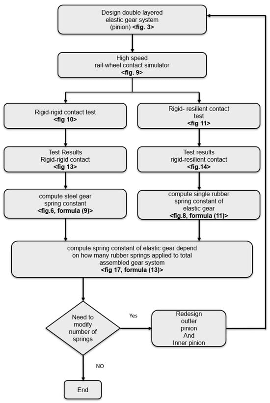
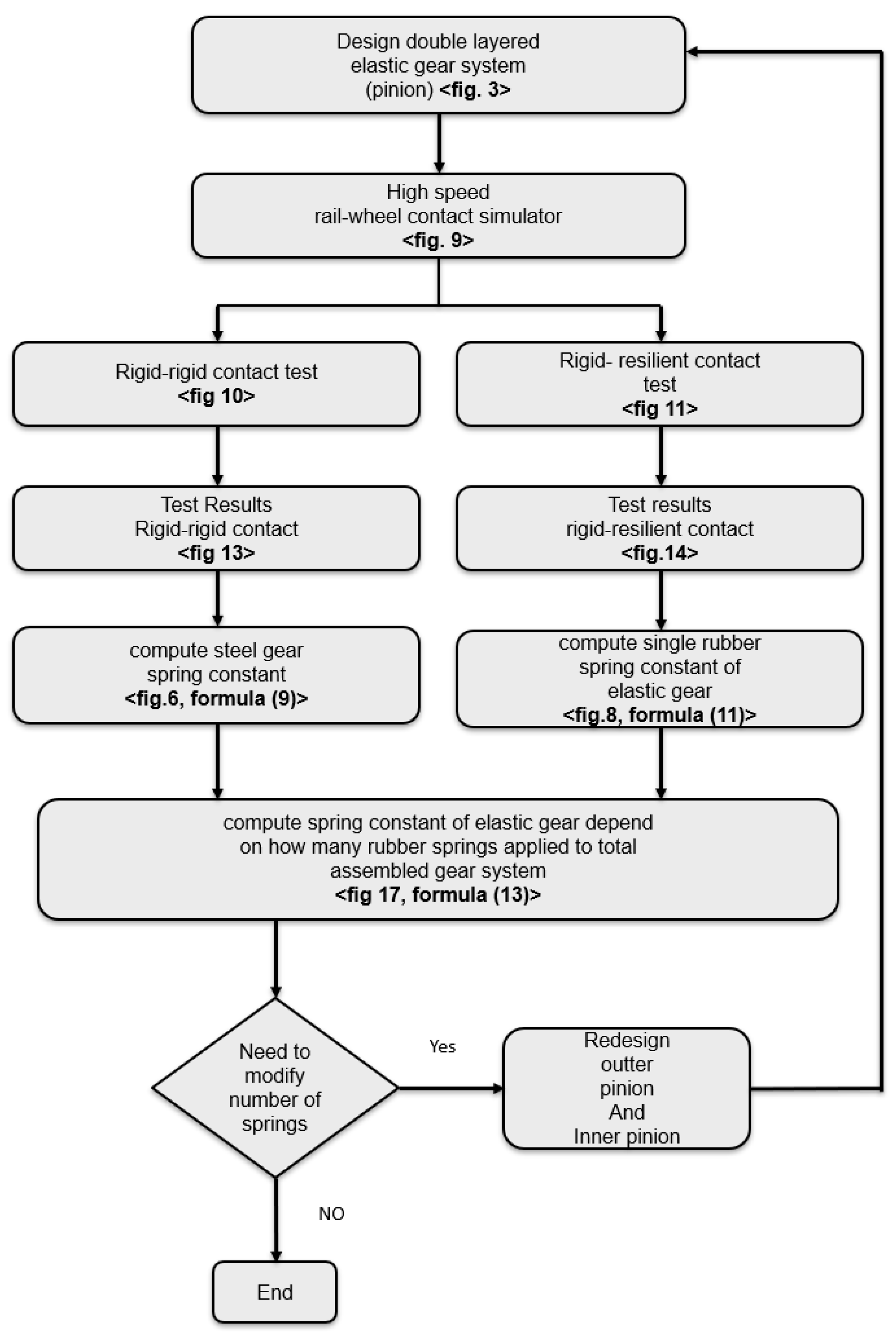
Figure 16 presents the optimisation schematic for varying the number of rubber springs. Table 4 compares the effective stiffness indicators of the steel gear and of the elastic gear with a single rubber spring. The total spring constant as a function of n rubber springs is given by Equation (15):
Figure 16.
Schematic diagram of the rubber spring number optimisation procedure.
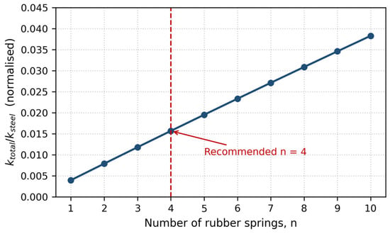
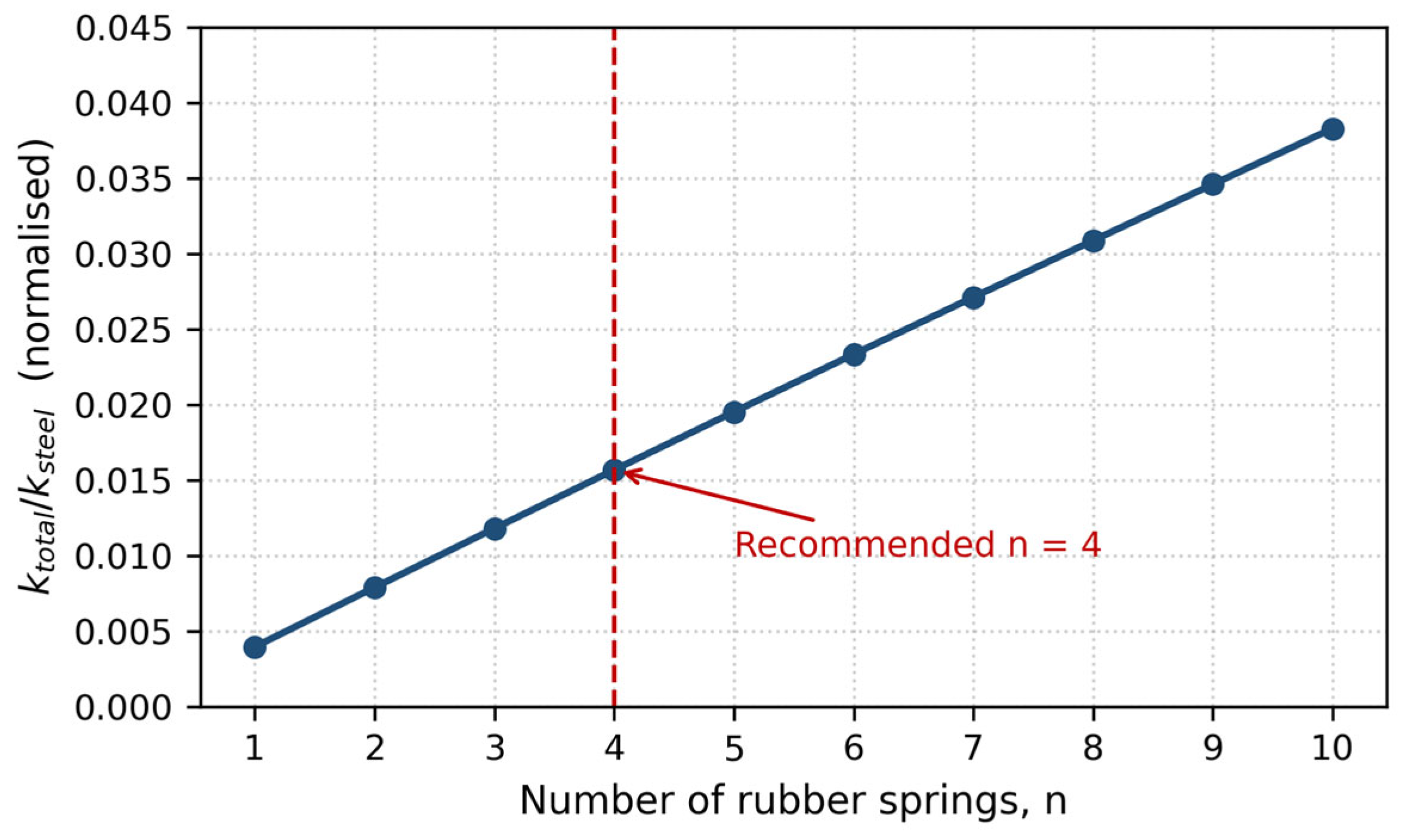
Figure 17 plots the computed total effective stiffness indicator, normalised by the rigid-baseline value, as a function of the number of rubber springs using Equation (15). When more than four rubber springs are applied, the incremental reduction in spring constant falls below 0.5%, indicating diminishing returns. Four rubber springs are thus predicted to represent the practical optimum, subject to the load-distribution, torque-capacity and durability considerations set out in Section 4; direct experimental confirmation at intermediate spring counts is identified as future work. Increasing the number of springs further distributes load across elements, reducing per-spring stress and extending fatigue life, as discussed in Section 4.
Figure 17.
Computed total effective stiffness indicator of the elastic gear, normalised by the rigid-baseline value, as a function of the number of applied rubber springs.
3.4. Comparison of Calculated and Measured Response
Equations (1)–(4) can be evaluated independently of the vibration measurement using the gear data of Table 1, and the result compared with the measured response. Because both configurations were tested on the same rig with only the gear specimen exchanged, the excitation and the effective mass are common to the two tests, and Equation (7) gives the predicted ratio of transmitted accelerations as ACCrubber/ACCsteel = ktotal/ksteel. This is the quantity compared with the measured value of 6.4/160.7 = 0.0398.
For the steel path, the mesh stiffness of a spur gear pair scales linearly with face width, and the standard single-tooth-pair stiffness for steel gears of normal proportions is c = 14 N/(mm um) [17]. With the face width range of Table 1 this gives ksteel = c b = 4.2 × 10⁸ to 1.1 × 10⁹ N/m. For the rubber path, the compression stiffness of one pocketed element is K = Ea A/t with Ea = E0 (1 + 2 k S2), the shape factor of a cylindrical element being S = dr/(4 t). Over the ranges of Table 1 this gives 1.0 × 10⁵ to 2.6 × 10⁶ N/m per element, and hence Krubber = 1.0 × 10⁶ to 2.6 × 10⁷ N/m for the ten-spring prototype. Because the rubber path is two to three orders of magnitude softer than the steel path, the series combination of Equation (4) is dominated by the rubber term and ktotal is approximately equal to Krubber.
The predicted acceleration ratio is therefore in the range 0.0009 to 0.061, within which the measured value of 0.0398 falls (Table 5). The model and the measurement are thus consistent, and the comparison confirms the central modelling assumption of the study, namely that inserting a compliant element two to three orders of magnitude softer than the tooth-contact path reduces the transmitted acceleration by a comparable factor. The width of the predicted band reflects the sensitivity of the calculation to face width, element geometry and compound hardness; narrowing it to a point comparison requires the as-built dimensions, and this is the reason the design procedure of Section 3.3 is formulated in terms of measured ratios rather than calculated absolute stiffness.
Table 5.
Calculated and measured effective stiffness of the two configurations. The calculated column is a sensitivity range obtained from the parameter ranges of Table 1; the measured value falls within it.
Residual differences between the calculated band and the measured value arise from three known sources, discussed in Section 4: the hysteretic damping of the rubber and the contact damping at the mesh, both neglected in the model; the distinction between the identified magnitude of complex dynamic stiffness and the purely elastic stiffness (Section 2.4); and the reduction in a rotating assembly to a single-degree-of-freedom translational model. Residual discrepancy between the calculated and measured ratio is expected from three known sources, and is discussed in Section 4: the hysteretic damping of the rubber and the contact damping at the mesh, both neglected in the model; the distinction between the identified magnitude of complex dynamic stiffness and the purely elastic stiffness (Section 2.4); and the reduction in a rotating assembly to a single-degree-of-freedom translational model.
4. Discussion
The experimental results show that the double-layered elastic gear reduces the vertical vibrational acceleration from 160.7 m/s2 to 6.4 m/s2—a factor of 25.1—under identical loading. This outcome follows directly from the series arrangement of the rubber compliance with the rigid tooth-contact stiffness (Section 2.3). For a single-degree-of-freedom representation of the mesh, the steady-state acceleration transmitted for a given excitation force scales with the effective contact stiffness; placing a soft rubber element in series with the much stiffer steel contact reduces the combined stiffness to approximately that of the rubber alone, because in a series combination the smaller stiffness dominates. The measured order-of-magnitude attenuation is therefore consistent with the stiffness reduction predicted by the kinematic model and with the established finding that effective contact stiffness governs the amplitude of forced gear vibration [2,6].
Expressed as a dimensionless ratio, the equivalent vertical stiffness of the elastic gear is reduced by approximately 99.6% relative to the rigid steel gear (Table 2). This ratio is the most robust statement of the optimisation result, because it is independent of the absolute stiffness calibration. The stiffness-reduction curve as a function of spring number follows a hyperbolic decay (Figure 16, Equation (15)): a single rubber spring already realises about 99.6% of the maximum achievable reduction, so from a purely vibrational standpoint one spring would suffice. The recommended four-spring configuration is therefore governed not by vibration performance but by mechanical load distribution—concentrating the full axle load on one element raises its compressive stress and cyclic strain, which, given the temperature- and amplitude-dependent stiffening and cyclic softening characteristic of rubber [7,8], would shorten fatigue life. Four springs distribute the load while retaining essentially the full attenuation benefit, defining the practical optimum between performance and durability.
4.1. Comparison with Alternative Vibration-Reduction Measures
The proposed in-gear compliance can be positioned against the principal alternative measures on four criteria: the point of intervention in the load path, the attenuation mechanism, the effect on load-carrying capacity, and maintainability. Rubber couplings and resilient wheels attenuate transmission along the drivetrain but act downstream of the mesh, so the gear-tooth and bearing loads themselves are not reduced. Constrained-layer damping treatments dissipate energy in the structure but typically achieve substantially smaller reductions than the insertion of compliance directly at the excitation source. Tooth-profile modification reduces transmission-error excitation at the design load but loses effectiveness away from that load, which is a significant limitation for rack railways in which the traction load varies strongly with gradient. The double-layered elastic gear attenuates the excitation at its source across operating conditions while preserving the standard load-bearing tooth geometry, at the cost of introducing an elastomeric component that requires periodic inspection.
Although elastomeric bushings are widely applied for vibration attenuation in the automotive field, the structural configuration and the load paths of railway rack-and-pinion propulsion differ substantially from automotive suspension and driveline applications, so those results cannot be transferred directly to the present problem [9,11]. This reinforces the need for the application-specific evaluation reported here.
4.2. Application to Rubber Compound Selection
The identified stiffness constitutes a design specification for the rubber path, and this specification may be met either by element geometry or by the choice of compound. For a pocketed element loaded in compression, the required stiffness per element K determines the required apparent compression modulus through Ea = K t/A, where t is the element thickness and A the loaded area. The apparent modulus is related to the intrinsic Young modulus through the shape factor S by Ea = E0 (1 + 2 k S2), so that E0 = Ea/(1 + 2 k S2) is the intrinsic property required of the compound. This value maps directly onto a hardness range in Shore A and hence onto candidate compound families, so the procedure returns a material requirement in addition to a spring count.
Three further criteria govern the selection. Where resonance margin is a concern, the loss factor becomes a selection variable in its own right, and compounds are chosen for their loss factor as well as for their modulus, recognising the accompanying penalties of heat build-up and increased temperature sensitivity. For mountain-railway service the low-temperature behaviour of the compound is a binding constraint, because the dynamic stiffening that occurs as the glass transition region is approached degrades the attenuation [8]; this consideration favours compound families with a low glass transition temperature and good low-temperature resilience, such as natural rubber, over compounds selected solely for high damping. Fatigue crack-growth resistance enters as a third criterion, consistent with the load-distribution analysis of Section 4.3.
4.3. Load Distribution, Fatigue Life and Load-Carrying Capacity
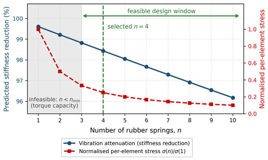
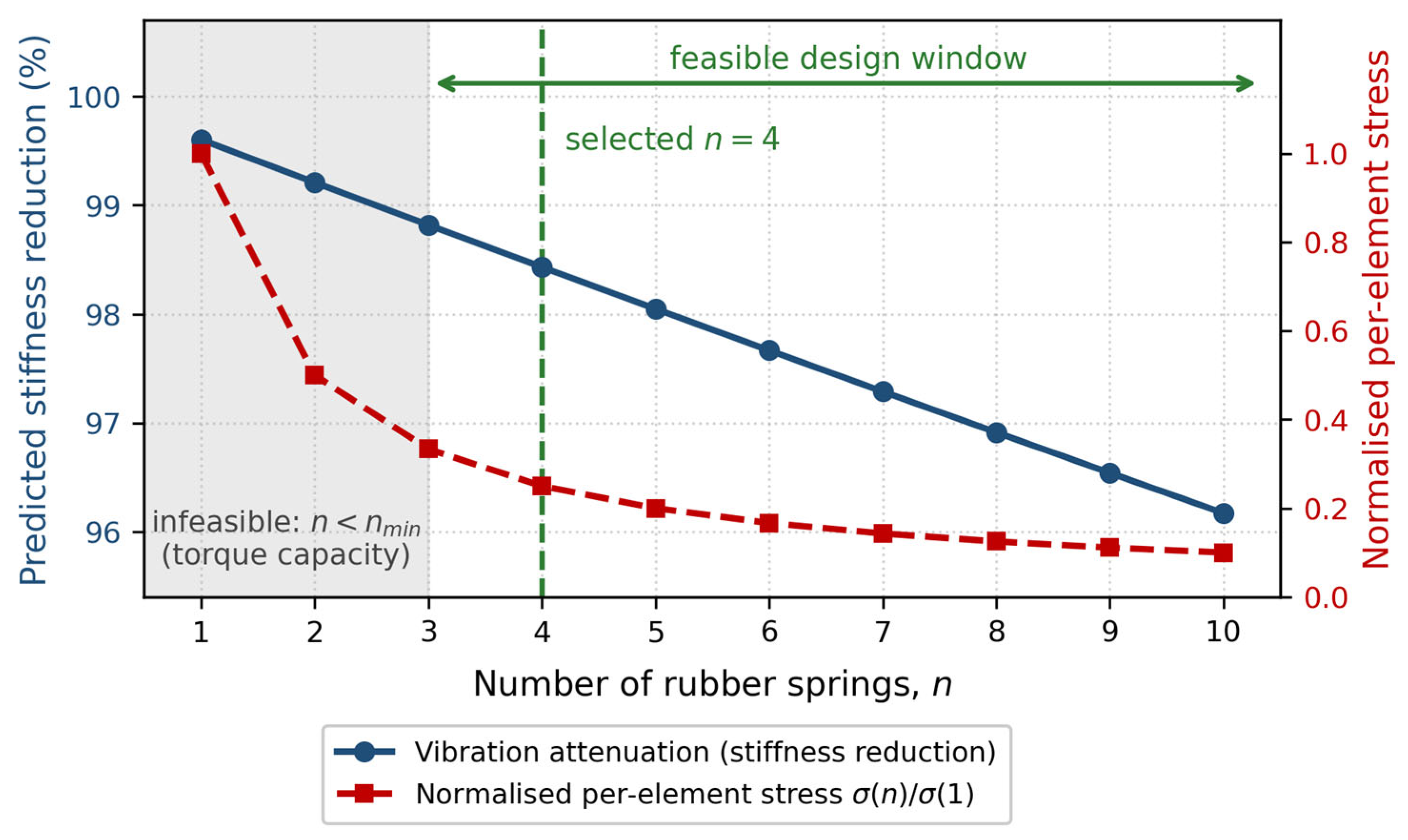
For n nominally identical springs equally spaced around the pitch circle and equally loaded, the force carried by each element is F/n, so the nominal compressive stress scales as 1/n. Table 6 sets out the resulting trade-off for the tested load: the predicted stiffness reduction falls only slowly with increasing spring number, from 99.60% at n = 1 to 96.17% at n = 10, whereas the per-element stress falls in inverse proportion to n. From the standpoint of vibration attenuation alone, a single spring would therefore be sufficient, since it already realises 99.6% of the achievable reduction.
Table 6.
Trade-off between vibration attenuation and per-element load as a function of the number of rubber springs, for the 250 N test condition.
Durability considerations act in the opposite direction. Elastomer fatigue life is commonly described by crack-growth models in which the life scales as a power of the strain energy density, with an exponent of approximately two for natural rubber compounds [18]. Since the strain energy density scales with the square of the nominal stress in the small-strain range, a fourfold reduction in per-element stress, corresponding to a change from one spring to four, implies an increase in predicted life of roughly two orders of magnitude. This is presented as an order-of-magnitude scaling argument rather than as a validated fatigue prediction; a certified value requires finite-element analysis of the element under combined compression and shear together with fatigue testing.
A third constraint arises from load-carrying capacity, which also determines how the elastic gear compares with the conventional design. Because the double-layered gear retains the tooth geometry, module, face width and material of the conventional gear, the tooth root bending capacity and the surface durability of the rack–pinion mesh are nominally identical for the two designs; the load-carrying capacity ratio is therefore not governed by the teeth. In the elastic gear, however, the full driving torque must be transmitted between the inner and outer pinion through the n rubber springs, so the transmissible torque is Telastic = n Fallow rs, where Fallow is the allowable load per element and rs the pitch radius of the spring locations. The capacity ratio relative to the conventional gear is thus min(Ttooth, n Fallow rs)/Ttooth, and for the present prototype it is the rubber term that binds.
This yields a lower bound on the spring count, nmin = Trequired/(Fallow rs), which must be satisfied for the drive to transmit the required tractive torque on the design gradient. With the pitch radius derived in Section 2.1, the torque demand follows from the tractive force as Trequired = Ft rp with rp = 220 mm, so the constraint may be written directly in terms of the tractive force as nmin = Ft rp/(Fallow rs). The constraint is linear in the tractive force and inversely proportional to both the allowable element load and the spring pitch radius, so increasing the pitch radius at which the springs are located is as effective as increasing their individual capacity. The selection of the spring number is accordingly the intersection of three constraints rather than a single criterion: vibration attenuation, which favours few springs; per-element stress and fatigue life, which scale as 1/n and favour many; and torque-transmission capacity, which imposes n at least equal to nmin. The recommended configuration is the smallest spring count that satisfies the capacity and durability constraints while retaining essentially the full attenuation benefit.
Figure 18 presents the resulting design window. The vibration attenuation predicted by Equation (15) falls slowly and monotonically with spring number, from 99.60% at n = 1 to 96.17% at n = 10, while the per-element stress falls as 1/n; the capacity constraint excludes all counts below nmin. The selected configuration is the smallest spring count lying inside the feasible window, since this maximises attenuation subject to capacity and durability. The figure is drawn with an illustrative value of nmin; substituting the tractive force and the element rating for a particular installation moves the boundary horizontally without altering the shape of either curve, so the selection rule itself is general.
Figure 18.
Design window for the rubber spring count, showing the predicted vibration attenuation, the normalised per-element stress, and the region excluded by the torque-transmission capacity constraint. The value of nmin shown is illustrative; it is fixed for a given installation by the tractive force, the allowable element load and the spring pitch radius.
This construction also answers the question of relative load-carrying capacity directly. For any configuration satisfying n greater than or equal to nmin the elastic gear transmits the full design torque, and its capacity relative to the conventional gear is unity, since the tooth geometry is unchanged; below that threshold the capacity ratio falls in proportion to n, as n Fallow rs/Ttooth. The elastic gear therefore involves no capacity penalty provided the spring count and element rating are chosen to satisfy the bound, which is the design condition that Figure 18 expresses.
Several sources of uncertainty qualify these results. The reported spring constants are effective, linearised values inferred from measured acceleration through the mass–spring relation, and therefore embed the specific load amplitude (250 N), rotational speed (240 rpm, ≈20 km/h), and ambient temperature of the test. Because rubber dynamic stiffness rises at lower temperatures and higher frequencies [8], the attenuation realised in service may differ from the laboratory value and most plausibly degrades under cold mountain conditions. Moreover, the linear spring model does not represent the hysteretic damping or amplitude-dependent response that govern rubber under large cyclic strain [7,8]; the derived stiffness should accordingly be interpreted as a design-stage screening estimate rather than a constitutive material property.
The present evaluation is further restricted to vertical vibrational acceleration, whereas a complete comfort and safety assessment requires the lateral and longitudinal components and the frequency content of the response, evaluated against the relevant ride-comfort and wheel–rail dynamic criteria. Within this scope, the measured attenuation is of the same order as the reductions reported for rubber-element vibration isolation in railway running gear [8], supporting the physical plausibility of the result while reinforcing the need for multi-axis, multi-condition validation.
The restriction to the vertical direction is supported by the triaxial screening measurements described in Section 2.5, in which the two horizontal components were small relative to the dominant vertical component. It is nevertheless acknowledged that the primary mesh excitation associated with transmission error acts along the line of action, and that the tangential component manifests principally as torque ripple which the present instrumentation was not configured to resolve. The vertical path reported here is the path through which the load is transmitted into the bogie frame and hence governs carbody vibration and ride comfort [8]. Multi-axis measurement, including tangential force and torque instrumentation, is planned for the vehicle-level test stage, consistent with the multi-directional responses reported for rack vehicle–track coupled systems [9,10].
Taken together, these findings substantiate the central claim of the study: embedding rubber springs within the gear, rather than at the coupling, attenuates rack–pinion vibration at its source while preserving the load-bearing tooth geometry, and the required number of springs can be selected systematically from measured data. The contribution is thus methodological—a reproducible procedure linking a single prototype measurement to an optimised spring count—rather than a claim of new elastomer physics.
4.4. Validity Envelope, Model Limitations and Transferability
All reported values apply to the tested condition: an applied axle load of 250 N, a rotational speed of 240 rpm corresponding to approximately 20 km/h, a gear-mesh frequency of 88 Hz, an ambient temperature of approximately 20 °C, and the specific bushing-grade elastomer used. Rubber dynamic stiffness increases with decreasing temperature and increasing frequency and decreases with increasing strain amplitude [8,15,16], so the attenuation measured at approximately 20 °C represents an upper bound on the attenuation available under cold mountain conditions, and this should be treated as a design caution rather than left implicit. The transferable contribution is the design procedure rather than the particular numerical values: the procedure requires one baseline measurement and one prototype measurement at the operating condition of interest, and the structure of Equation (15) is unchanged by the operating point. Because both measurements are taken under identical conditions, the ratio on which the procedure depends is substantially less sensitive to operating condition than either absolute value.
Three limitations of the model itself follow from the assumptions stated in Section 2.4. First, because hysteretic damping is the mechanism that limits response amplification at resonance, the undamped model cannot be used to assess resonance margins, and it is applicable only in the stiffness-controlled regime in which the present measurements were taken. The rubber hysteresis that is omitted from the model is beneficial in service, since it suppresses resonant build-up. Second, the measured attenuation of 25.1 is a property of the physical system and therefore already contains whatever contribution the rubber damping makes; it is the model, and not the measurement, that attributes the reduction solely to stiffness. Third, the identified quantities are magnitudes of complex dynamic stiffness rather than storage stiffnesses, with the bounded systematic error quantified in Section 2.4. Removing these limitations requires replacing the purely elastic element with an established viscoelastic representation, either the five-parameter formulation of Berg, which combines elastic, frictional and viscous contributions [15], or a fractional-derivative formulation of the type applied to rubber isolators by Sjoberg and Kari [16]; either would represent amplitude, frequency and temperature dependence together with the phase shift between load and displacement, and would permit the resonance and transient analyses that the present model cannot support.
Finally, the transferability of these bench results to service conditions is bounded. The tests were conducted on an indoor rail–wheel contact simulator and therefore exclude track irregularity, rack installation error, and vehicle bounce and roll. The absolute acceleration levels reported here are specific to the rig and are not claimed to represent on-track levels; the transferable outputs are the relative ranking of the two configurations and the design procedure itself. Repeatability was assessed by testing each configuration five to six times with closely similar outcomes, and the most conservative elastic-gear record is reported, so the quoted attenuation represents a lower bound; the archived records do not, however, retain the full measurement bandwidth, so frequency-domain characterisation at the 88 Hz gear-mesh frequency remains to be performed. The next stage is the incorporation of the elastic gear into a rack vehicle–track coupled dynamics model of the type reported in [9,10,11], with excitation derived from measured track irregularity and rack installation tolerance, followed by line testing on the target route and consistent with the field measurements reported in [1].
Future work should quantify the fatigue life of the rubber springs as a function of spring number and applied load, ideally through finite-element analysis under combined compression and shear, and should extend the single-objective stiffness criterion of Equation (15) to a multi-objective formulation that simultaneously minimises vibrational acceleration and maximises fatigue life across the full operating envelope of gradient force, speed, and temperature.
5. Conclusions
An elastic double-layered gear incorporating internal rubber springs was designed and experimentally evaluated as a means of reducing vibration in a Korean rack railway propulsion system. The following conclusions are drawn:
- Rubber springs inserted within the elastic gear exhibit nonlinear material behaviour, making direct in situ measurement of spring constants impractical. The methodology presented here, deriving effective dynamic stiffness indicators from measured vibrational acceleration data using Equations (8)–(11), provides a viable indirect characterisation approach for assembled gear systems. Because the indicators are formed as ratios, they are independent of the effective mass and of the unmeasured displacement amplitude.
- A systematic optimisation process was developed to determine the appropriate number of rubber springs: (i) manufacture and test a prototype with an initial spring count; (ii) evaluate vibrational performance against the steel gear baseline; and (iii) apply Equation (15) to predict the normalised stiffness as a function of spring number. The procedure returns, in addition, a specification for the rubber compound, as set out in Section 4.2.
- Kinematic models for both the conventional steel gear (Figure 5) and the elastic rubber gear (Figure 7) were established, and the individual stiffness components were evaluated from the gear data of Table 1 and compared with the values identified from measurement in Section 3.4.
- Experimental testing confirmed that the elastic gear with ten rubber springs achieved a 25.1-fold reduction in vertical vibrational acceleration relative to the steel gear baseline (6.4 m/s2 vs. 160.7 m/s2); the reported values are the most conservative of five to six repeated runs per configuration, so the attenuation ratio represents a lower bound.
- Application of Equations (9), (11) and (15) predicts four rubber springs as the practical optimum, beyond which the incremental stiffness change falls below 0.5%. The selection of four springs is governed jointly by vibration attenuation, by load distribution across the rubber elements, and by the torque-transmission capacity constraint set out in Section 4.3; direct experimental validation at intermediate spring counts is planned in the subsequent vehicle development programme.
- When the optimal number of rubber springs is determined, the outer pinion gear can be manufactured with the appropriate number of spring pockets, enabling direct application of this methodology to mountain railway propulsion system development.
Author Contributions
Conceptualization, H.S.M.; methodology, H.S.M.; investigation, H.S.M. and C.W.P.; formal analysis, H.S.M. and C.W.P.; data curation, C.W.P.; writing—original draft preparation, H.S.M.; writing—review and editing, H.S.M. and C.W.P.; supervision, C.W.P. All authors have read and agreed to the published version of the manuscript.
Funding
This work is supported by the Korea Agency for Infrastructure Technology Advancement (KAIA) grant funded by the Ministry of Land, Infrastructure and Transport (Grant RS-0023-00239464).
Institutional Review Board Statement
Not applicable.
Informed Consent Statement
Not applicable.
Data Availability Statement
The data presented in this study are available on request from the corresponding author. The data are not publicly available due to institutional data management policies.
Acknowledgments
The authors gratefully acknowledge the Korea Railroad Research Institute (KRRI) for providing access to the high-speed rail–wheel contact simulator and for technical support during the experimental testing program.
Conflicts of Interest
The authors declare no conflicts of interest. The funders had no role in the design of the study; in the collection, analysis, or interpretation of data; in the writing of the manuscript; or in the decision to publish the results.
Abbreviations
The following abbreviations are used in this manuscript:
| ACC | Vibrational acceleration (m/s2) |
| ACCratio | Vibrational acceleration attenuation ratio (dimensionless) |
| KRRI | Korea Railroad Research Institute |
| MCK | Mass–damper–spring (mass, damping coefficient, stiffness) system |
| TE | Transmission error |
| rpm | Revolutions per minute |
| Rack | Toothed rack rail installed at the centre of the track; engages with the pinion to generate propulsive force |
| Outer Pinion | Outer gear layer of the double-layered elastic gear assembly; meshes directly with the rack |
| Inner Pinion | Inner gear layer of the double-layered elastic gear assembly; connected to the drive shaft |
| kr | Tooth root bending stiffness (N/m) |
| koc | Contact surface stiffness derived from Hertzian contact theory (N/m) |
| kopo | Tooth profile stiffness of the outer pinion (N/m) |
| kopi | Tooth profile stiffness of the inner pinion (N/m) |
| kipr | Stiffness of the inner pinion–rubber spring contact interface (N/m) |
| kipo | Stiffness of the inner pinion–outer pinion contact interface (N/m) |
| m | Effective mass of the gear assembly (kg) |
| n | Number of rubber springs (dimensionless) |
| F | Applied axle load (N) |
| Fallow | Allowable load per rubber element (N) |
| x | Vibratory displacement amplitude at the measurement point (m) |
| c | Damping coefficient (N s/m) |
| g | Gravitational acceleration, 9.8 m/s2 |
| Z | Number of pinion teeth (dimensionless) |
| fm | Gear-mesh frequency, Z N/60 (Hz) |
| rs | Pitch radius of the rubber spring locations (m) |
| rp | Pitch radius of the pinion (m) |
| T | Transmitted torque (N m) |
| kh | Hertzian contact stiffness (N/m) |
| kb, ks, ka | Tooth bending, shear and axial compressive stiffness (N/m) |
| kf | Fillet-foundation stiffness (N/m) |
| k* | Complex dynamic stiffness (N/m) |
| η | Loss factor of the elastomer (dimensionless) |
| S | Shape factor of the rubber element (dimensionless) |
| Ea | Apparent compression modulus of the rubber element (MPa) |
| E0 | Intrinsic Young modulus of the rubber compound (MPa) |
| RMS | Root mean square |
References
- Chen, Z.; Yang, G.; Chen, Z.; Zhang, H.; Yang, J.; Zhai, W. Dynamic characteristics analysis of rack railway track system under traction conditions by experimental test. Railw. Eng. Sci. 2026, 34, 40–54. [Google Scholar] [CrossRef] [Scilit]
- Özgüven, H.N.; Houser, D.R. Mathematical models used in gear dynamics—A review. J. Sound Vib. 1988, 121, 383–411. [Google Scholar] [CrossRef] [Scilit]
- Kahraman, A.; Singh, R. Non-linear dynamics of a spur gear pair. J. Sound Vib. 1990, 142, 49–75. [Google Scholar] [CrossRef] [Scilit]
- Yang, D.C.H.; Sun, Z.S. A rotary model for spur gear dynamics. J. Mech. Transm. Autom. Des. 1985, 107, 529–535. [Google Scholar] [CrossRef] [Scilit]
- Abbes, M.S.; Trigui, M.; Chaari, F.; Fakhfakh, T.; Haddar, M. Dynamic behavior modeling of flexible gear system by the elastic foundation theory in presence of defects. Eur. J. Mech. A/Solids 2010, 29, 887–896. [Google Scholar] [CrossRef] [Scilit]
- Abbes, M.S.; Bouaziz, S.; Chaari, F.; Maatar, M.; Haddar, M. An acoustic-structural interaction modelling for the evaluation of a gearbox-radiated noise. Int. J. Mech. Sci. 2008, 50, 569–577. [Google Scholar] [CrossRef] [Scilit]
- Green, I.; English, C. Analysis of elastomeric O-ring seals in compression using the finite element method. Tribol. Trans. 1992, 35, 83–88. [Google Scholar] [CrossRef] [Scilit]
- Gong, D.; Duan, Y.; Wang, K.; Zhou, J. Modelling rubber dynamic stiffness for numerical predictions of the effects of temperature and speed on the vibration of a railway vehicle car body. J. Sound Vib. 2019, 449, 121–139. [Google Scholar] [CrossRef] [Scilit]
- Chen, Z.; Ning, J.; Yang, G.; Chen, Z.; Yang, J.; Zhai, W. Dynamic characteristics of rack vehicle-track coupled system on large slope line: Theoretical modelling and experimental validation. Veh. Syst. Dyn. 2024, 62, 2304–2331. [Google Scholar] [CrossRef] [Scilit]
- Ning, J.; Chen, Z.; Chen, Z.; Yang, J.; Zhai, W. Dynamic behaviours of rack vehicle-track system considering rack flexibility under gear-rack mesh impact. Int. J. Rail Transp. 2025, 13, 490–510. [Google Scholar] [CrossRef] [Scilit]
- Shen, L.; Zhou, Z.; Wu, X.; He, S.; Yang, N.; Luo, Y. Study on the gear-rack meshing dynamic performance based on a multi-body dynamic model of rack rail vehicle. Adv. Mech. Eng. 2024, 16, 16878132241286640. [Google Scholar] [CrossRef] [Scilit]
- Wang, Q.; Li, D.; Zeng, J.; Peng, X.; Wei, L.; Du, W. A diagnostic method of freight wagons hunting performance based on wayside hunting detection system. Measurement 2024, 227, 114274. [Google Scholar] [CrossRef] [Scilit]
- Tian, X. Dynamic Simulation for System Response of Gearbox Including Localized Gear Faults. Master’s Thesis, University of Alberta, Edmonton, AL, Canada, 2004. [Google Scholar]
- Sainsot, P.; Velex, P.; Duverger, O. Contribution of gear body to tooth deflections—A new bidimensional analytical formula. J. Mech. Des. 2004, 126, 748–752. [Google Scholar] [CrossRef] [Scilit]
- Berg, M. A non-linear rubber spring model for rail vehicle dynamics analysis. Veh. Syst. Dyn. 1998, 30, 197–212. [Google Scholar] [CrossRef] [Scilit]
- Sjöberg, M.; Kari, L. Non-linear behavior of a rubber isolator system using fractional derivatives. Veh. Syst. Dyn. 2002, 37, 217–236. [Google Scholar] [CrossRef] [Scilit]
- ISO 6336-1:2019; Calculation of Load Capacity of Spur and Helical Gears—Part 1: Basic Principles, Introduction and General Influence Factors. International Organization for Standardization: Geneva, Switzerland, 2019.
- Mars, W.V.; Fatemi, A. A literature survey on fatigue analysis approaches for rubber. Int. J. Fatigue 2002, 24, 949–961. [Google Scholar] [CrossRef] [Scilit]

Disclaimer/Publisher’s Note: The statements, opinions and data contained in all publications are solely those of the individual author(s) and contributor(s) and not of MDPI and/or the editor(s). MDPI and/or the editor(s) disclaim responsibility for any injury to people or property resulting from any ideas, methods, instructions or products referred to in the content. |
© 2026 by the authors. Licensee MDPI, Basel, Switzerland. This article is an open access article distributed under the terms and conditions of the Creative Commons Attribution (CC BY) license.