


Abstract
The dynamic behavior of the DS306 detacher, a critical component in industrial fiber processing lines, plays a decisive role in maintenance performance and overall operational reliability. This study introduces a strengthened preventive maintenance strategy that leverages vibration analysis and dynamic modeling with a strong emphasis on early fault anticipation. A detailed numerical finite element model of the detacher was developed to determine its natural frequencies, critical modes, and dynamic response under real operating conditions. Experimental vibration measurements were conducted to validate the numerical model and identify characteristic frequencies associated with imbalance and wear. The results show that the proposed predictive framework not only reproduces the machine’s dynamic behavior with high accuracy but also anticipates mechanical degradation trends well before the occurrence of critical failures. This early-warning capability allows maintenance teams to plan interventions proactively, significantly reducing unexpected downtime, avoiding cascading damage, and improving long-term equipment availability. Overall, the study provides a robust and practical methodology for dynamic diagnosis, fault prediction, and optimized preventive maintenance in industrial rotating machinery.
1. Introduction
The reduction in solid material size, or comminution, is one of the fundamental operations of modern industrial processes. It plays a central role in various sectors such as agri-food, pharmaceuticals, chemicals, construction materials, and the mining industry, where it enables the transformation of coarse raw materials into finer particles that are easier to handle, process, and integrate into subsequent production stages. This operation therefore contributes to improving the efficiency of industrial processes by enhancing mixture homogenization, increasing the specific surface area available for chemical reactions, facilitating heat transfer, and optimizing product transport and storage [1,2,3].
To achieve these objectives, different types of mills and grinders are used, relying on various mechanical mechanisms such as impact, compression, shear, or abrasion [4,5,6]. Among them, knife mills are particularly well suited for processing fibrous, elastic, or soft materials [5]. Thanks to their cutting blades, they allow precise control of particle size while limiting heat generation, which is essential in agri-food processes, particularly in cereal transformation and flour production [5,7,8].
Unlike conventional hammer mills, which rely on high-energy impact forces to break down grains, semolina detachers operate through a more controlled and selective mechanical action. Instead of aggressively reducing particle size, detachers are designed to gently separate residual endosperm from bran particles after the milling stages. Their rotor–stator configuration, equipped with pins or beaters rather than hammers, prioritizes surface abrasion and selective detachment over violent impact. This functional specificity results in lower energy consumption, reduced thermal stress on the product, and a more uniform semolina quality [6,7]. However, it also makes detachers particularly sensitive to dynamic defects—such as imbalance, misalignment, and bearing wear—since their efficiency depends on maintaining precise rotor–stator clearances and stable operating conditions. These characteristics create unique diagnostic challenges that differ significantly from those of classical impact-based mills [9,10].
In addition to conventional vibration-based approaches, other monitoring methods, such as temperature measurement, are essential for assessing the condition of machinery [11,12]. Indeed, temperature variations in the friction zone serve as a key technical indicator of changes in the operating conditions of bearings. A practical study of the thermal regime for diagnosing bearing assemblies in mechanical transmissions has been conducted. The methodology involves analyzing bearing temperatures, establishing the relationship between surface temperature and the friction zone, and identifying suitable areas for thermal measurement. Thermographic observations have confirmed that this approach provides a reliable tool for detecting abnormal friction and mechanical wear, thereby offering a robust framework for the preventive maintenance of rotating machinery [9,10,12].
However, the performance of these high-speed rotary machines strongly depends on their dynamic behavior. The literature shows that defects such as rotor imbalance, misalignment, bearing degradation, or resonance phenomena can generate high vibration levels, leading to premature wear, reduced productivity, and unplanned shutdowns [13,14]. To prevent such malfunctions, numerous studies have explored vibration-based diagnostic techniques and machine condition monitoring [13,15,16]. These works propose a variety of approaches ranging from time- and frequency-domain analyses to advanced signal-processing methods, including envelope analysis, wavelet transforms, and artificial intelligence-based algorithms for automatic fault classification [17,18,19]. Despite these advances, no consensus has yet been reached regarding best practices for sensor placement, selection of vibration indicators, or definition of fault thresholds. Moreover, most existing studies focus primarily on heavy industrial machinery—such as mining mills, compressors, and turbines—and seldom address equipment dedicated to agri-food processing. As a result, very few works have investigated the dynamic behavior, failure modes, or vibration-based diagnostic strategies applicable to semolina detachers or similar milling devices. This scarcity of targeted research limits the understanding of previous contributions and makes it difficult to clearly position the novelty of the present work within the existing scientific landscape.
This lack of specific references makes it difficult to directly transpose existing diagnostic methods to such machines. It therefore justifies the need for dedicated investigations that provide a more detailed analysis of previous work on similar equipment and tasks, while adapting methodologies to the particular constraints of flour production lines. Within this context, the present work aims to thoroughly analyze the dynamic behavior of the DS306 semolina detacher, an essential piece of equipment involved in the final stage of flour production. The study proposes an integrated approach combining numerical modeling, modal characterization, and experimental vibration monitoring in order to establish a reliable diagnostic framework and identify the defects most likely to degrade machine performance. The findings then allow the formulation of concrete recommendations to optimize maintenance, reduce production downtime, and improve equipment longevity.
2. Materials and Methods
This study focuses on a specific type of industrial rotary machine: the DS306 Detacher (Bühler AG, Uzwil, Switzerland), used in the final stage of the wheat flour production process. Its primary function is to mechanically separate the remaining bran particles from the endosperm, thereby enhancing the purity and fineness of the flour. Positioned downstream from the main milling units, the DS306 operates with high-speed rotating blades that impact the product flow, detaching adhering bran and improving the overall yield and product quality [8,9].
Like any high-speed rotating machinery, the DS306 is subject to complex dynamic phenomena during operation. Problems such as rotor imbalance, shaft misalignment, bearing wear, or structural resonance can induce harmful vibration levels. These vibrations not only deteriorate machine performance but also accelerate mechanical wear, increase maintenance frequency, and lead to unplanned production stoppages [20]. Moreover, excessive vibration can propagate to neighboring machines and supporting structures, creating system-wide inefficiencies and higher operational costs [21]. Understanding these dynamic behaviors is thus crucial for implementing an effective predictive maintenance strategy and ensuring long-term equipment reliability.
To address the preventive aspect highlighted in the methodology, it is essential to apply it actively during equipment operation. This involves continuous or periodic monitoring of critical parameters such as vibration levels, bearing temperatures, and shaft alignment. Real-time or scheduled analyses of these signals allow early detection of deviations from normal operating conditions, enabling timely interventions such as rotor balancing, bearing lubrication, or minor realignment. By implementing these preventive actions proactively, potential mechanical faults can be mitigated before they develop into severe failures. Consequently, the equipment’s operational reliability is enhanced, downtime is minimized, and the service life of critical components is extended
2.1. Objectives of the Study
The primary objective of this work is to perform a comprehensive dynamic characterization of the DS306 Detacher under real operating conditions. Specifically, the study seeks to:
- Experimental validation of numerical models:Verify the consistency between the natural frequencies and vibration modes obtained from numerical simulations and the experimental vibration measurements, ensuring that the FEM model accurately represents the rotor’s real dynamic behavior.
- Early detection of mechanical anomalies:Identify and diagnose emerging mechanical faults, such as rotor imbalance, bearing wear, and clearance in bearing housings, through spectral analysis and temporal monitoring of vibrations.
- Assessment of maintenance interventions’ effectiveness:Evaluate the impact of corrective actions (bearing replacement, shaft realignment, and rotor balancing) on reducing vibration amplitudes and stabilizing mechanical operation, confirming their effectiveness in preventing critical failures.
- Support for predictive maintenance and operational optimization:Provide a quantitative basis for implementing predictive maintenance strategies by identifying potential resonance zones and enabling proactive interventions before major failures occur.
Through this systematic investigation, the study aims to contribute to process optimization, equipment durability, and product quality improvement within the flour milling industry. The insights obtained may also serve as a reference model for diagnosing similar rotary systems in other industrial sectors [10,22].
2.2. Industrial Case Study: DS306 in Operation
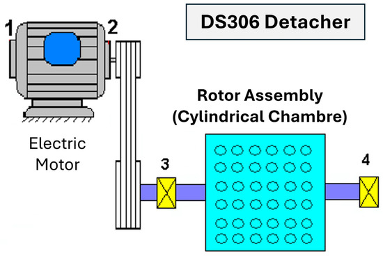
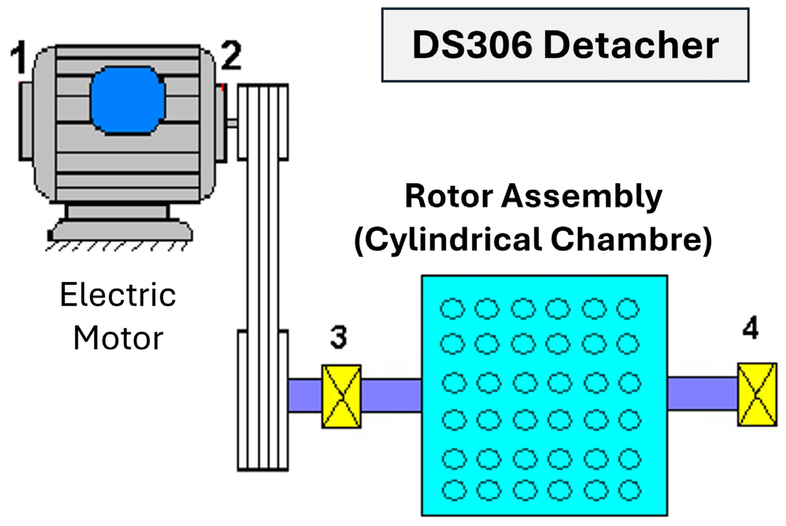
A practical case study was conducted in a semolina milling plant located in Algeria, focusing on a DS306 Detacher installed in the dispatch section of the facility [8,9]. Figure 1 shows the electric motor (1), belt transmission (2), and rotor assembly (cylindrical chamber) supported by two bearings (3, 4). The configuration illustrates the mechanical linkage between the driving motor and the detacher’s rotating cylinder [13,14]. The goal was to assess its operational state and determine the origin of persistent vibration issues affecting the process line [14,23,24].
Figure 1.
Schematic diagram of the DS306 Detacher drive system.
A practical case study was conducted at a semolina milling facility in Algeria, focusing on a DS306 Detacher installed in the dispatch section.
Clarification regarding Figure 1: Position (2) indicates the belt transmission assembly, not a bearing as might be mistakenly assumed. This transmission connects the electric motor to the horizontal shaft, transmitting torque to the rotor while maintaining proper alignment and tension. Correct identification of this component is essential for understanding the power flow and for accurate vibration analysis of the detacher system.
2.2.1. Description of the Studied System
The DS306 detacher is a key operational unit within an industrial semolina milling line. Positioned in the dispatch section, its primary function is to mechanically separate residual endosperm from bran, completing the final flour-conditioning stage following the roller milling process. The system is driven by a 2.55 kW electric motor operating at 1485 rpm, which transmits motion to the detacher shaft equipped with four rows of blades arranged at a radial distance of 250 mm from the rotor center (corresponding to a 500 mm rotor diameter).
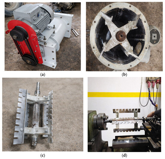
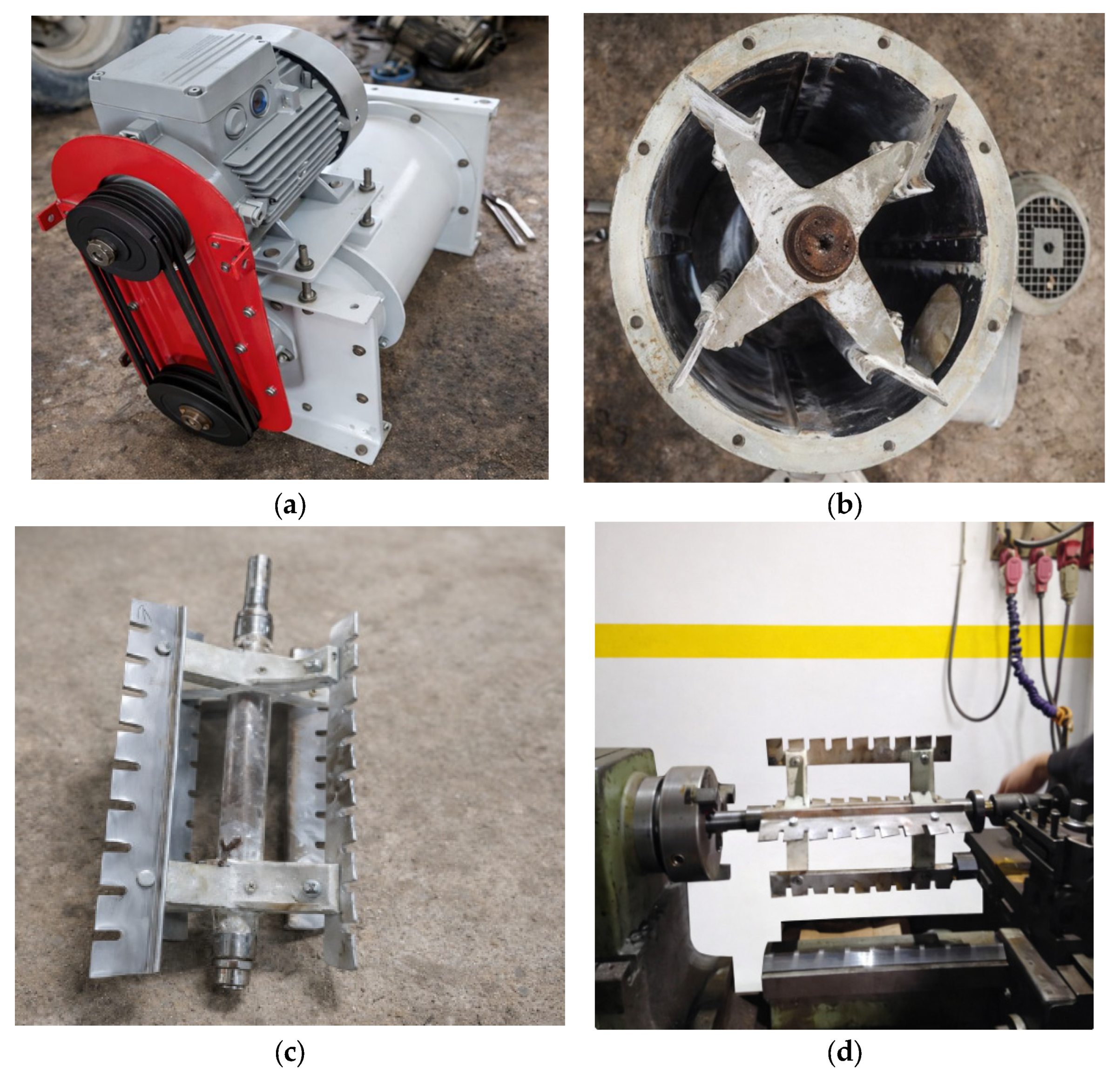
The detacher rotor has a working width of 600 mm and operates at 990 rpm. It offers a nominal throughput capacity of 1200 kg/h and a total rotor mass of 8.4 kg (Figure 2a–c).
Figure 2.
Photographs of the DS306 Detacher during disassembly and inspection: (a) General view of the DS306 Detacher installed in the milling plant, showing the electric motor and belt-drive transmission. (b) Internal chamber view displaying the four-blade rotor configuration. (c) Rotor assembly removed from the housing, showing detachable blades and shaft supports. (d) Rotor balancing operation performed on a lathe prior to vibration testing.
This configuration ensures high rotational energy and continuous particle impact, providing efficient separation of bran residues from the flour stream.
2.2.2. Selection of Vibration Measurement Points
The vibration analyzer used is the MOVIPACK from 01 dB Stell (Limonest, France), a two-channel device equipped with several modules, namely: a data collector, an analyzer, and a balancer.
The machine monitoring system, based on the vibration analysis method, as well as the configuration of the vibration measurement points, is carried out using the XPR 300 software installed on a PC. This software enables machine setups to be uploaded to the vibration analyzer.
After completing the on-site measurement campaign, the vibration measurement points for each machine are downloaded to the laboratory PC for detailed analysis and diagnosis. This procedure is part of the condition-based maintenance strategy, relying on vibration analysis techniques and the monitoring of rotating machinery using this method.
The vibration sensor used during the measurements is the ASH 210 accelerometer (ASH Technologies, Dublin, Ireland), with the following specifications:
- Frequency range: 2 Hz–10 kHz.
- Resonance frequency: >20 kHz.
- Measurement range: 80 g (with g = 9.81 m/s2).
- Storage and operating temperature: −20 °C to +120 °C.
- The maximum admissible temperature is limited by the cable, between 90 °C and 120 °C.
Following ISO 10816 [17] and ISO 7919 [25] standards, accelerometers were positioned to capture representative vibrational signatures at the motor-side, mid-span, and detacher bearings [13,20]. Measurements along horizontal and vertical directions enable comprehensive fault detection, particularly for bearing defects, misalignment, and rotor imbalance [13,22].
The accuracy of vibration-based diagnostics in rotating machinery strongly depends on the placement of measurement points. For reliable assessment, sensors must be located at positions that capture the most representative vibrational signatures of the mechanical system [13,20]. In this study, the primary goal was to evaluate the overall mechanical health of the DS306 detacher by monitoring:
- The bearing condition, as bearings are typically the first components to exhibit degradation;
- The shaft line dynamics, particularly at the rotor section, which is the critical rotating component under investigation.
To achieve this, accelerometers were mounted on the bearing housings, where vibration transmission from internal faults (imbalance, misalignment, bearing defects) is most significant. This placement allows for early fault detection, enabling predictive maintenance before critical failure occurs [10,21]. The vibration acquisition system was configured to cover a wide frequency range, including:
- Low-frequency components associated with unbalance and misalignment,
- Mid- to high-frequency bands related to bearing defects, gear meshing, and mechanical looseness [22].
Measurements were collected along two orthogonal directions—horizontal and vertical—at each sensor location. This dual-axis configuration allows comprehensive evaluation, since certain faults manifest more prominently in one direction than in the other [13].
All measurement procedures adhered to the ISO 10816 and ISO 7919 standards, for evaluating vibration severity in rotating machinery, ensuring comparability with industrial benchmarks and international diagnostic criteria [14].
2.3. Mathematical Modeling and Vibratory Behavior of the Mechanical System
The DS306 detacher consists of a horizontal rotor supported by two rolling bearings, on which multiple cutting blades are mounted, as shown in Figure 2. The entire assembly is installed on a rigid concrete foundation, and the machine operates at a nominal frequency of 24.85 Hz. To evaluate the vibratory response of this system, a mathematical model based on classical rotor dynamics was developed [16,23,24].
The FEM model of the DS306 Detacher was implemented in SolidWorks Simulation 2024 to analyze the dynamic behavior and structural stiffness of the equipment. This section presents a set of fundamental equations that form the theoretical basis of the model. Although these equations are not directly solved by the authors, they clearly illustrate the methodology used by SolidWorks and help to understand the underlying physical principles, including geometric stiffness, rotor inertia, and rotor–stator interactions [16,20].
The general Equation (1) of motion governing the dynamic behavior of the system can be expressed as:
where:
- , and are the mass, damping, and stiffness matrices, respectively,
- , and represent the vectors of generalized displacements, velocities, and accelerations,
- denotes the vector of generalized external forces applied to the system as a function of time.
2.3.1. Free Undamped Vibrations
The free vibration behavior of the DS306 rotor system can be described using the classical equations of motion derived from structural dynamics theory. Neglecting external forces and damping allows the determination of the system’s natural frequencies and associated mode shapes, as detailed below.
In the absence of damping [C] = 0 and external forces {F(t)} = 0, the system exhibits free vibrations, described by Equation (2):
This homogeneous differential equation admits harmonic solutions of the form (3):
where s = jω is the Laplace variable j2 = −1. Substituting into the motion Equation (4) yields:
which can be expressed as the classical eigenvalue problem:
With .
Non-trivial solutions exist only if the determinant of the coefficient matrix vanishes:
This represents the characteristic equation of the system, whose roots correspond to the natural frequencies, and the associated vectors {Xi} define the mode shapes of vibration. Based on these theoretical foundations, a numerical modal analysis of the DS306 rotor was performed using the finite element method (FEM) implemented in SolidWorks Simulation. This approach enables the determination of natural frequencies and mode shapes under real boundary conditions, providing a direct comparison with experimental vibration measurements.
2.3.2. Two-Degree-of-Freedom System Modeling
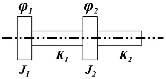
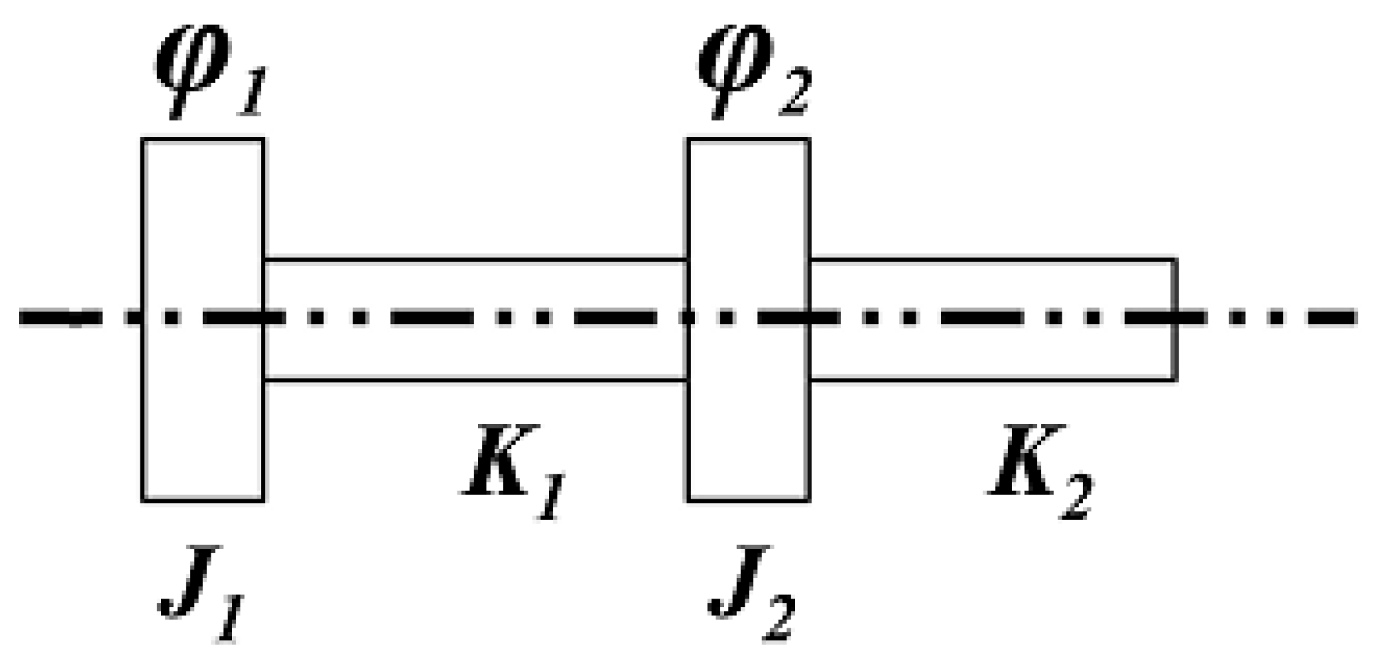
The transmission shaft of the DS306 detacher consists of a driven pulley and a cutting rotor connected by a flexible shaft supported by two bearings. The system can be modeled as a two-degree-of-freedom torsional system, as illustrated in Figure 3. The simplified model comprises:
Figure 3.
Theoretical model of the two-degree-of-freedom torsional system representing the DS306 transmission shaft.
- A disc of moment of inertia I1 representing the motor pulley,
- A disc of moment of inertia I2 corresponding to the detacher rotor,
- Two torsional stiffnesses K1 and K2 representing the elastic deformation of the shaft between the discs.
The dynamic behavior of this torsional system is governed by the following equations of motion for this simplified system can be written as:
where ϕ1 and ϕ2 denote the angular displacements of the pulley and the rotor, respectively. Developing these systems, we developed the following equation:
In matrix form, the system can be expressed as:
Or
The combined use of the general equations of motion and the simplified two-degree-of-freedom model provides a physically consistent and interpretable framework for analyzing the dynamic behavior of the DS306 detacher. This approach allows the determination of natural frequencies and mode shapes, which characterize the rotor’s dynamic response under real boundary conditions.
The simplified two-degree-of-freedom model is particularly useful for identifying torsional modes that are most sensitive to rotor imbalance or misalignment, providing a basis for predictive maintenance planning. By linking the system’s structural properties to its vibrational behavior, this framework serves as a theoretical reference for FEM simulations, enabling the comparison of analytical, numerical, and experimental results to validate the model.
Overall, this integrated modeling approach offers a simplified yet effective tool for predicting the vibrational behavior of the DS306, guiding subsequent numerical simulations and experimental validations that confirm critical frequencies and mode interactions observed in practice.
3. Results
3.1. Experimental Study
Following the analytical and numerical investigations presented in the previous sections, an experimental vibration monitoring campaign was conducted to validate the dynamic behavior of the DS306 detacher under real operating conditions. The objective of this experimental study was to correlate theoretical modal predictions with actual vibration responses, identify emerging mechanical faults, and assess the machine’s operational reliability over time. Continuous measurements were carried out on the DS306 drivetrain using accelerometers mounted at strategic positions along the bearings and shaft line. The main stages of this monitoring process, together with the historical evolution of vibration levels and maintenance interventions, are summarized below.
3.1.1. Machine Monitoring History
The vibration-based condition monitoring of the DS306 detacher was initiated on 3 June 2021, to assess its mechanical health and detect early-stage degradation phenomena. The initial spectral analysis revealed no critical anomalies, except for a slight shaft misalignment between the motor and the detacher, producing a moderate vibration level of 2.95 mm/s on the motor-side bearing (horizontal direction).
Subsequent periodic monitoring over four years (2021–2025) revealed progressive variations in the vibration amplitudes measured at the three main bearing positions. The chronological evolution of these values and the corresponding maintenance interventions are summarized in Table 1, which shows the vibration trends recorded between June 2021 and May 2025.
Table 1.
Summary of vibration measurements and maintenance interventions on the DS306 detacher.
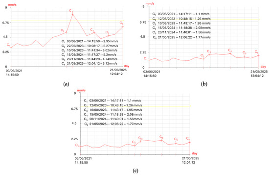
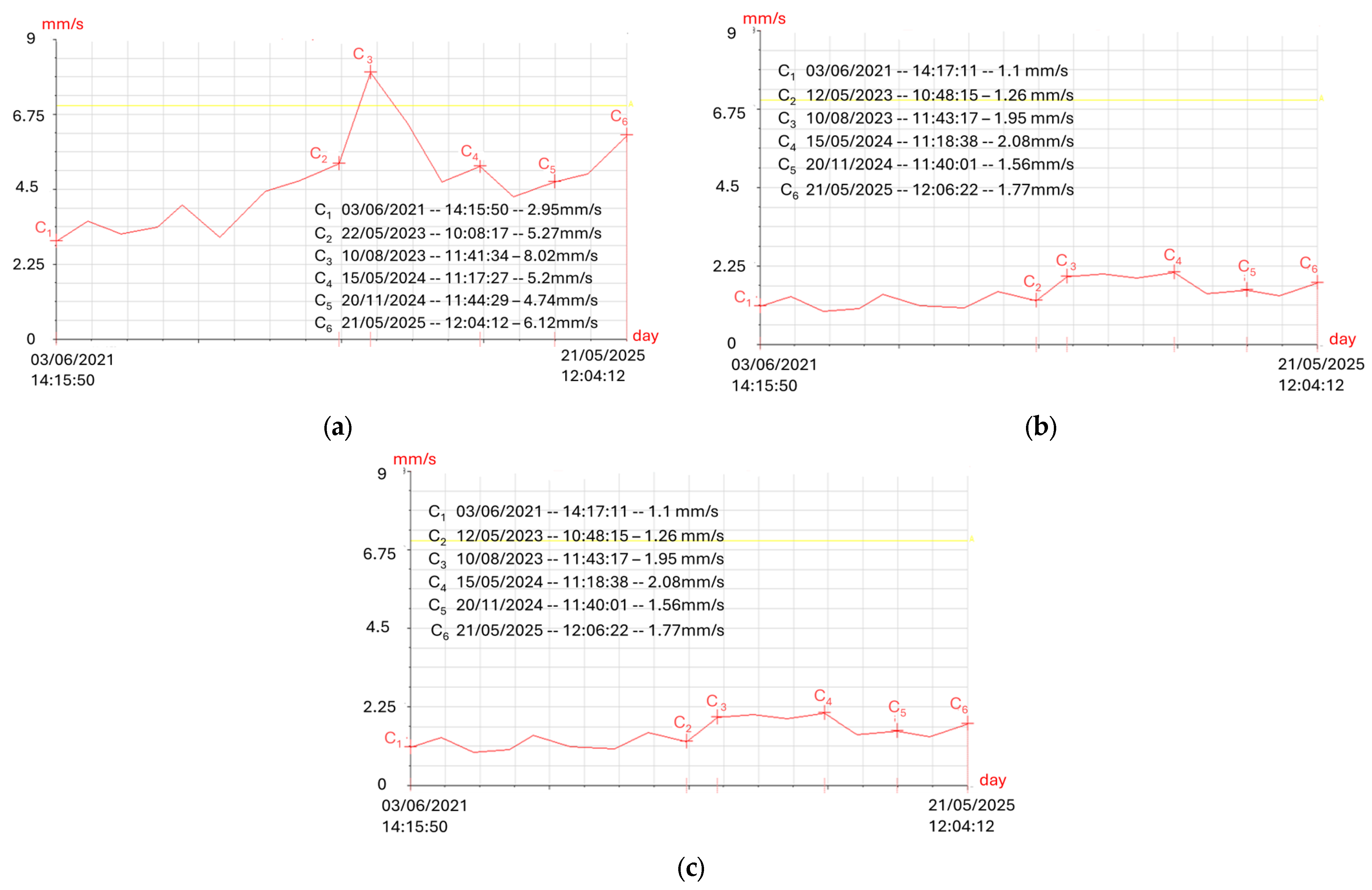
The vibration monitoring of the machine, carried out using vibration analysis methods, began on 3 June 2021. At that time, the spectral interpretation did not reveal any significant anomalies, except for a slight misalignment between the motor shaft and the shaft driving the detacher. This defect generated a global vibration level of 2.95 mm/s on the motor bearing in the horizontal direction, as shown by the trend curves (a, b, c) in Figure 4.
Figure 4.
Evolution of overall vibration velocity for the DS306 detacher between 2021 and 2025: (a) bearing level #02 (motor side); (b) bearing level #03 (intermediate support); (c) bearing level #04 (output side). The horizontal yellow lines represent reference vibration levels used for comparative and diagnostic purposes.
In total, 16 vibration measurement campaigns were conducted between 2021 and 2025. Based on the trend curves presented in the referenced figures, we analyzed in detail the last six (06) measurements, during which the vibration level began to increase significantly and became more pronounced, particularly after 10 August 2023.
The vibration comparison of the three DS306 detacher bearings shows that bearing #02 (motor-side) had the highest levels, reaching 8.02 mm/s before replacement and decreasing to 4.90 mm/s after maintenance. Bearing #03 (intermediate) experienced moderate vibrations, reducing from 2.68 mm/s to 1.50 mm/s after interventions. Bearing #04 (output-side) consistently showed the lowest values, stabilizing around 1.55 mm/s post-maintenance. Corrective actions, including rotor balancing and bearing replacements, effectively reduced vibrations for all bearings. Overall, the motor-side bearing was the most critical, while the other two bearings remained largely stable
A sharp increase in vibration amplitude was observed on 10 August 2023, reaching 8.02 mm/s at bearing level #02. According to the VDI 2056 international standard [23], this value corresponds to the alarm level, indicating the onset of a significant rotor imbalance in the detacher shaft. Following rotor balancing and bearing replacement, vibration levels decreased but remained slightly above the initial baseline, suggesting residual imbalance or minor shaft misalignment persisted in the system [24].
The temporal evolution of vibration velocity at the three monitored bearing locations is presented in Figure 4. These trend curves clearly demonstrate the progressive mechanical degradation of the DS306 detacher, followed by stabilization after each maintenance intervention.
The three graphs represent the temporal evolution of the overall vibration velocity (in mm/s) measured at the detacher’s bearing positions level #02, level #03, and level #04 between June 2021 and May 2025. Each curve illustrates the progressive change in vibration amplitude due to mechanical deterioration, maintenance interventions, and realignment operations.
- Bearing level 02 (Motor Side): The first graph in Figure 4a shows a steady increase in vibration amplitude from approximately 3 mm/s in 2021 to a maximum of 8.02 mm/s in August 2023, followed by a partial reduction after bearing replacement. The dominant fault signatures are associated with rotor imbalance and coupling misalignment, generating low-frequency excitations. After maintenance, vibration decreased to around 5 mm/s but did not return to its original baseline, suggesting residual unbalance or slight shaft misalignment persisted.
- Bearing level 03 (Intermediate Support): The second trend curve, in Figure 4b, displays lower and more stable vibration levels, fluctuating between 1.1 and 3 mm/s throughout the monitoring period. The small amplitude variations reflect transmitted vibration from the upstream motor–rotor assembly rather than local defects. The minor peaks observed around 2023 correspond to the same imbalance event seen on bearing level #02, confirming vibratory propagation along the shaft line but with attenuation due to the bearing stiffness and damping effects. No localized defect was identified at this position.
- Bearing N° 04 (Output Side): In the third graph in Figure 4c, the lowest vibration levels were recorded at this position (<2 mm/s). A slight rise in 2023 (≈1.9 mm/s) indicates a secondary excitation likely caused by the bearing-race clearance and subsequent replacement of the detacher bearings. After corrective maintenance, the vibration amplitude stabilized near 1.7 mm/s, signifying that the restoration procedure was effective and the residual vibration level is within acceptable limits (zone A/B under VDI 2056).
The overall vibration analysis confirms the development of a progressive imbalance in the DS306 detacher up to mid-2023, followed by effective corrective actions—including rotor balancing, bearing replacement, and system cleaning—that successfully restored acceptable operating conditions. From 2024 onward, the machine exhibited a stable mechanical response with no further critical anomalies. These results emphasize the crucial role of continuous vibration monitoring in predictive maintenance, as the temporal evolution of vibration signals provided early warning of mechanical degradation and enabled timely interventions before the occurrence of severe failures.
3.1.2. Vibration Diagnosis and Analysis of Results
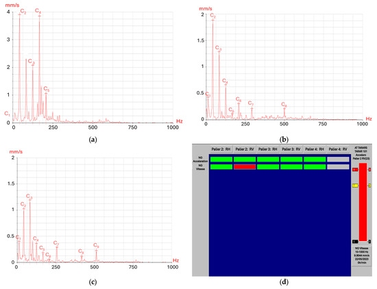
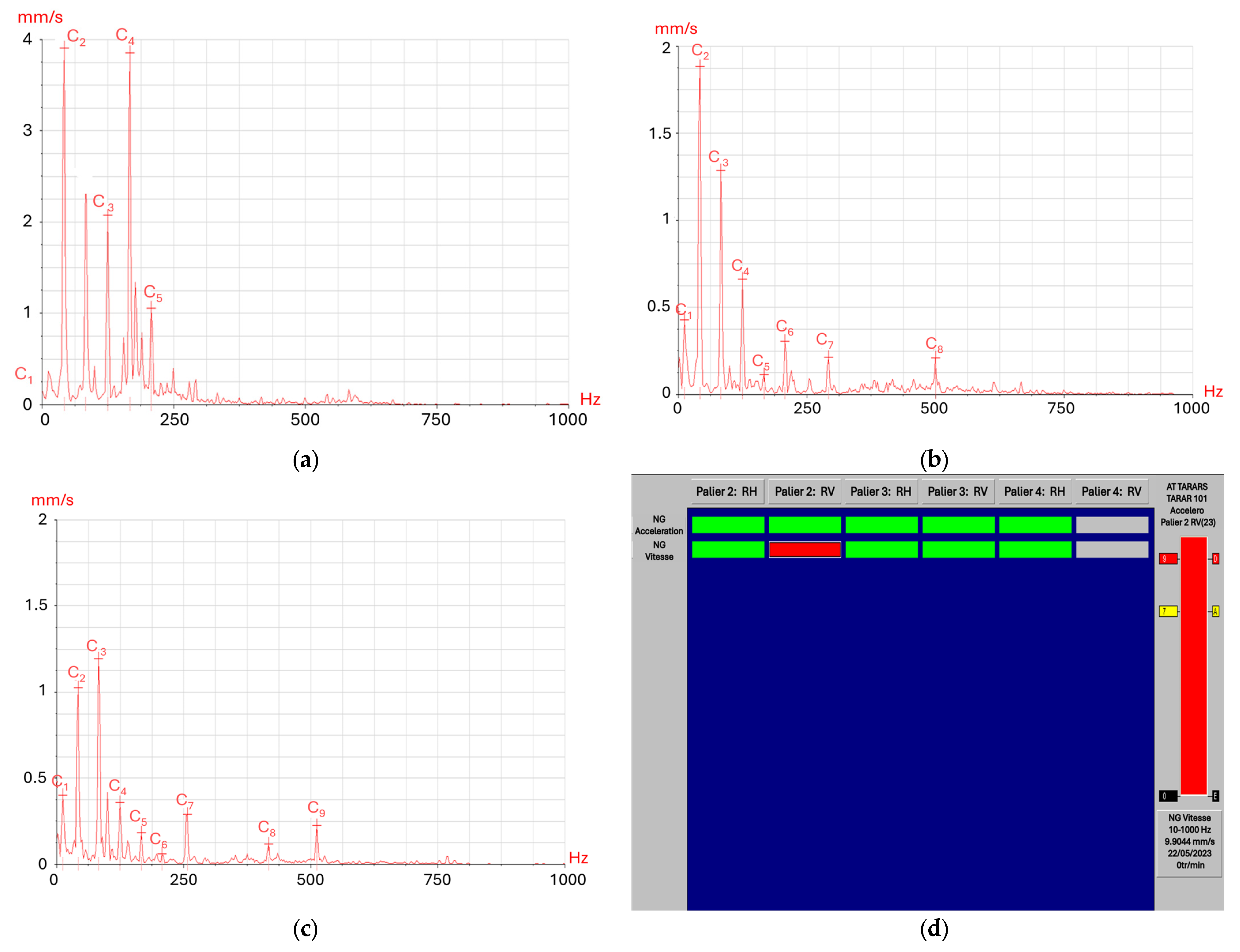
The spectral analysis of the vibration signals collected along the DS306 detacher drivetrain revealed several characteristic fault signatures indicative of mechanical degradation. The main vibration spectra, recorded on 10 August 2023, under nominal operating conditions, are presented in Figure 5. Spectral interpretation of the vibration data across the drivetrain confirmed several mechanical anomalies:
Figure 5.
Representative vibration spectra and diagnostic results for the DS306 detacher recorded on 10 August 2023: (a) bearing level #02 (motor side) showing imbalance and bearing fault peaks; (b) bearing level #03 (intermediate support) indicating impact-related harmonics; (c) bearing level #04 (output side) showing minor clearance effects; (d) SOPRAPHIN vibration severity map highlighting alarm condition at bearing level #02.
- Bearing Defects and Alarm Classification: The spectrum acquired at bearing level #02 (motor side, vertical direction) displayed dominant frequency peaks at multiples of the shaft rotational speed (1×, 2×, and 3×), as shown in Figure 5a. The amplitude of the fundamental component exceeded 4 mm/s RMS, corresponding to an overall vibration level of 8.02 mm/s, classified as alarm level under VDI 2056 standards.This spectral signature is characteristic of rotor unbalance combined with coupling misalignment, producing strong low-frequency harmonics. The elevated energy observed between 100 Hz and 200 Hz suggests the onset of defects in the bearing raceways, consistent with the mechanical inspection findings.
- Shaft Impact and Bearing Clearance Effects: The vibration spectra recorded at bearing level #03 and level 04 (Figure 5b,c) exhibited a series of broadband peaks at frequencies above 200 Hz, with sidebands around the bearing characteristic frequencies. These patterns are associated with periodic impacts between the rolling elements and the inner/outer races, indicative of bearing looseness or excessive clearance. The presence of multiple harmonics confirms a non-linear dynamic response, likely caused by transient contact and load redistribution along the rotor line.After bearing replacement and realignment, these high-frequency components decreased significantly, confirming that the observed anomalies were directly related to bearing wear rather than structural resonance.
- Global Vibration Severity Map: The vibration severity map generated by the SOPRAPHIN diagnostic interface is shown in Figure 5d. The color-coded display summarizes the overall condition of each bearing:
- The motor-side bearing (level 02) appears in the red alarm zone, confirming excessive vibration.
- The intermediate and output bearings (level 03, level 04) remain within the green zone, indicating acceptable operation.
This global view provides a comprehensive overview of the vibratory behavior along the detacher drivetrain.
The combined spectral and temporal analyses confirm that the dominant fault mechanism during 2023 was rotor unbalance coupled with bearing degradation, primarily affecting the motor-side bearing. Subsequent maintenance—comprising rotor balancing and replacement of all detacher bearings—effectively reduced the vibration amplitudes to acceptable levels. The post-maintenance spectra showed a significant reduction in low-frequency peaks and the disappearance of impact-related harmonics, indicating a return to stable dynamic behavior.
Vibration spectroscopy combined with trend monitoring is recognized as a reliable tool for predictive maintenance of industrial detachers, facilitating early fault detection and reducing unplanned downtime.
3.1.3. Maintenance Actions
Based on the vibration spectra and fault diagnoses discussed above, a series of corrective maintenance actions were undertaken to mitigate the identified mechanical anomalies and restore the DS306 detacher to stable operating conditions.
During the monitoring period, several corrective maintenance interventions were implemented to mitigate the identified vibration anomalies and restore stable operating conditions. The main actions included:
- Replacement of bearings (type 21307-E) in the detacher housings (level 03 and level 04), carried out on multiple occasions following abnormal vibration readings;
- Verification and adjustment of alignment between the motor and detacher shafts to minimize coupling-induced misalignment;
- Dynamic balancing of the detacher rotor assembly after each major maintenance operation to correct residual unbalance and ensure uniform load distribution.
These maintenance measures significantly reduced the overall vibration levels and extended the operational lifespan of the DS306 detacher. The practical observations obtained from these interventions will be compared with the numerical simulation results presented in the next section to validate the consistency between experimental data and the finite element modal analysis.
3.2. Numerical Simulation and Modal Analysis of Rotor System Results
This section presents the numerical simulation and modal analysis of the DS306 detacher rotor, performed to evaluate its dynamic characteristics and identify potential resonance conditions. The numerical study complements the experimental investigation by providing a detailed understanding of the system’s natural frequencies, mode shapes, and vibration behavior under realistic boundary conditions. Using finite element modeling (FEM), the rotor and shaft assembly were analyzed to determine the dominant flexural and torsional modes that govern the machine’s dynamic response. The results of this simulation are subsequently compared with experimental vibration data to validate the model and support predictive maintenance strategies.
3.2.1. Modeling and Boundary Conditions
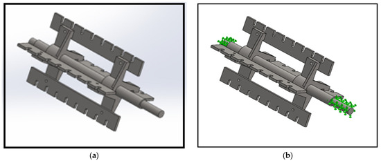
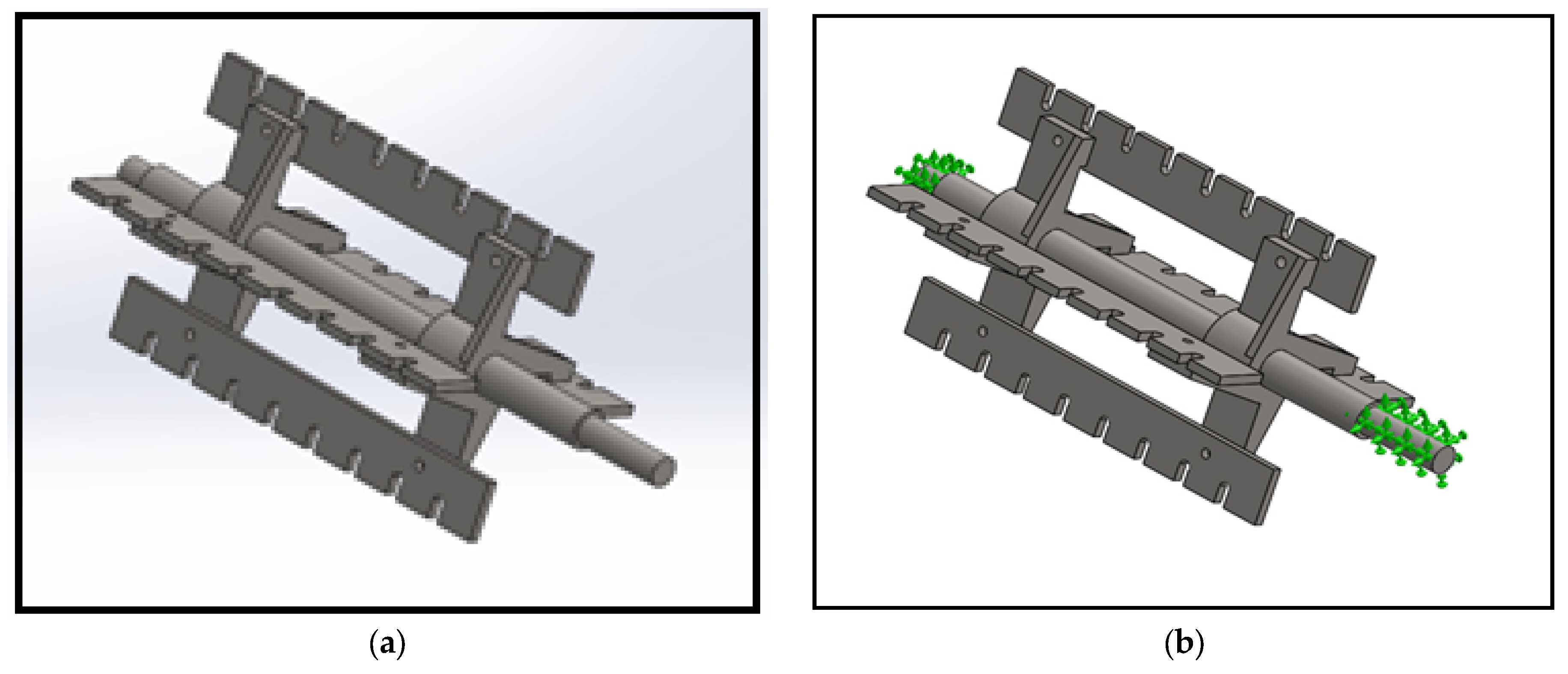
Before any dynamic study of a rotating system, a modal analysis is required to identify its natural frequencies and corresponding mode shapes. For this purpose, a detailed three-dimensional model of the DS306 detacher rotor was developed using SolidWorks Simulation, as shown in Figure 6a. The model faithfully reproduces the actual geometry of the detacher, including the main shaft, the detachable blades, and the support assemblies, in order to accurately capture the mass distribution and stiffness characteristics of the real system.
Figure 6.
Three-dimensional Model and boundary conditions: (a) 3D CAD model of the DS306 detacher with SolidWorks; (b) Application of boundary conditions with free torsional motion.
To simulate realistic operating conditions, boundary constraints were applied to represent the bearing housings that support the rotor. As illustrated in Figure 6b, both bearing ends were fixed in all translational degrees of freedom, while rotational motion around the shaft axis was maintained to allow torsional deformation. This configuration replicates the real mounting conditions of the DS306 detacher, where the rotor is supported by two rigid bearings but remains free to twist under dynamic loading.
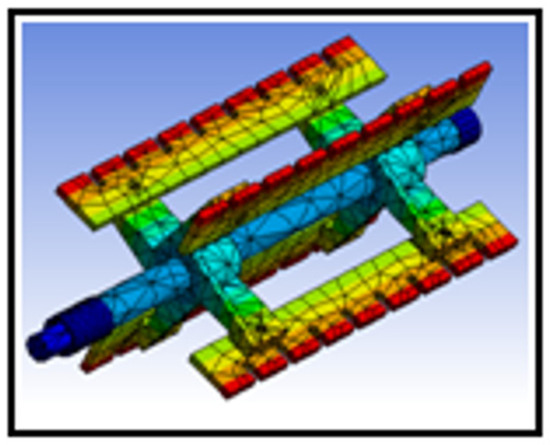
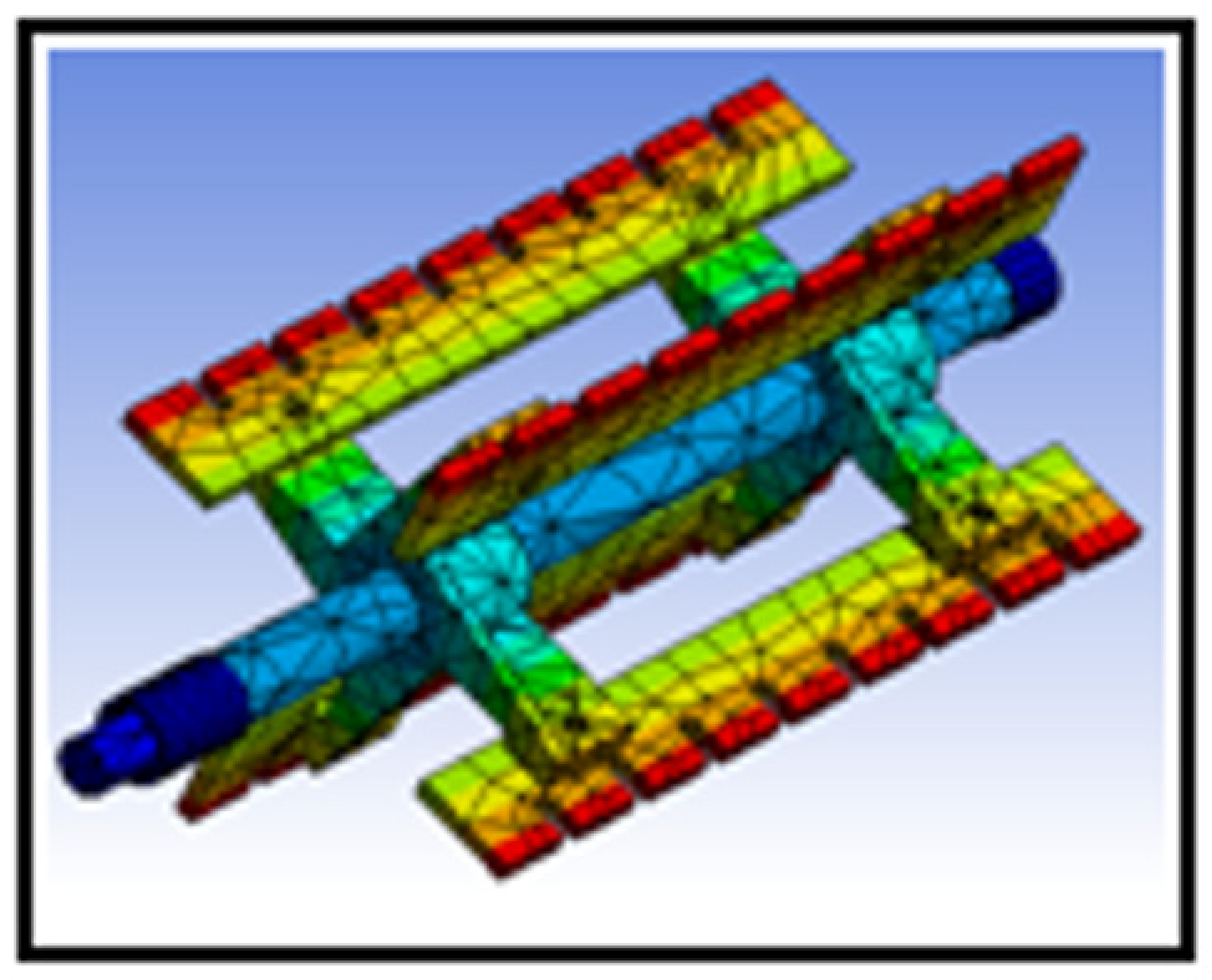
A volumetric finite element mesh composed of tetrahedral elements was then generated to discretize the model (see Figure 7). A mesh convergence analysis was carried out to ensure a satisfactory compromise between computational accuracy and processing time. The resulting mesh provided a stable estimate of the natural frequencies and guaranteed that the subsequent modal analysis would reliably reflect the true dynamic behavior of the rotor assembly.
Figure 7.
Finite element mesh of the DS306 rotor system composed of tetrahedral elements.
3.2.2. Modal Simulation Results
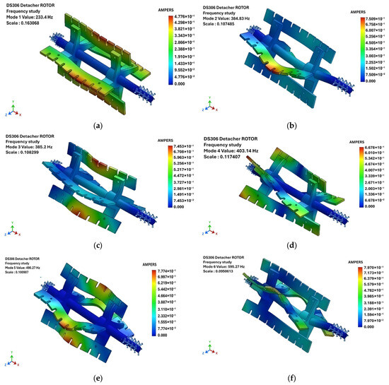
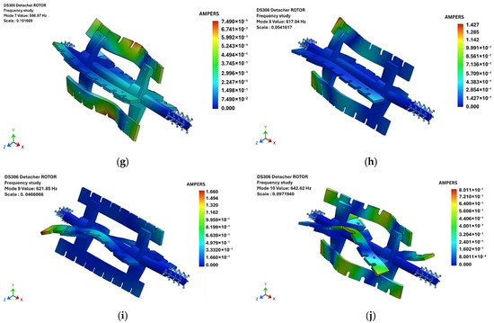
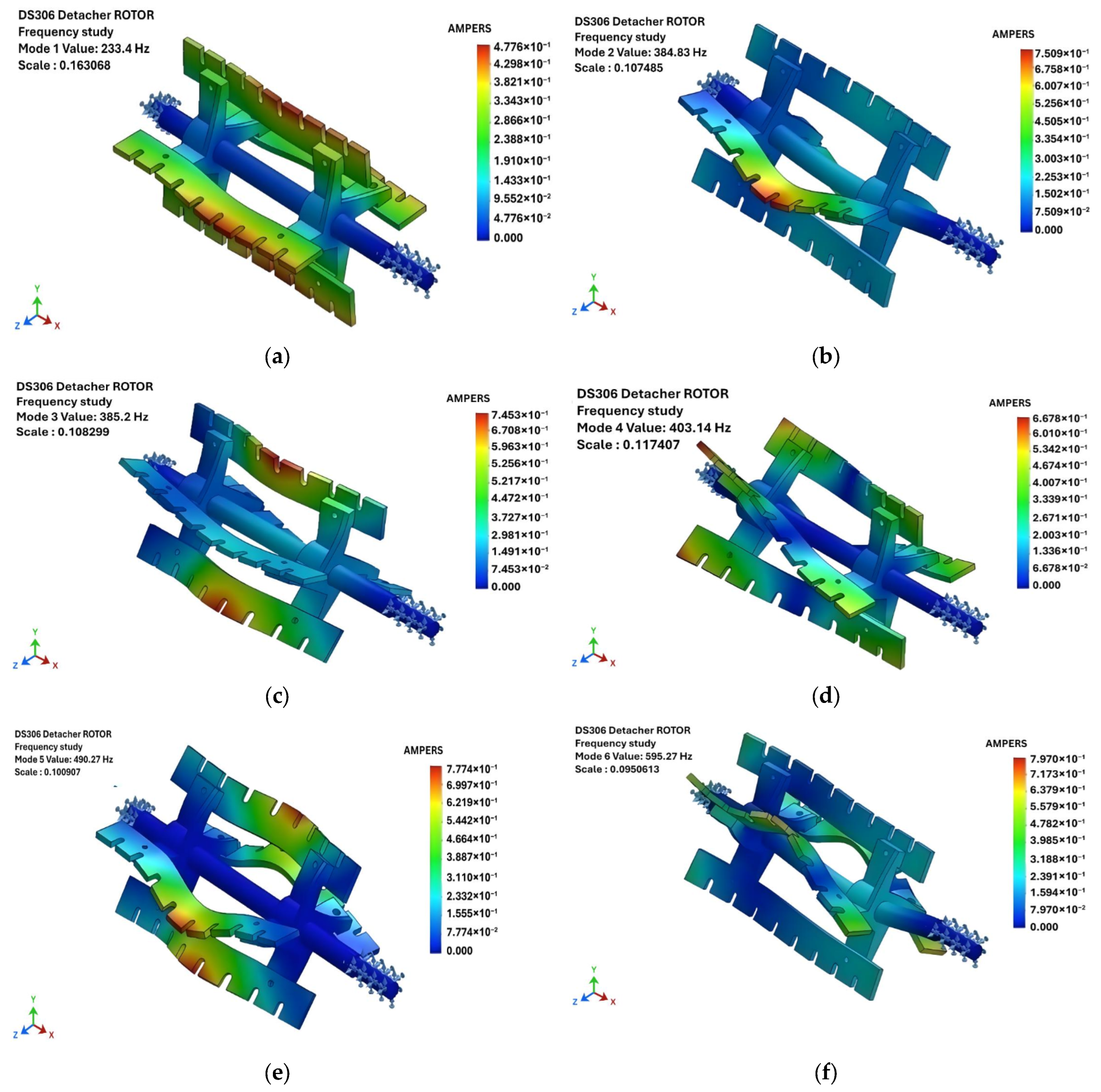
A numerical modal analysis was carried out on the DS306 detacher rotor–bearing assembly to determine its natural frequencies and corresponding mode shapes. This study makes it possible to identify the principal deformation patterns of the rotor and to assess potential resonance risks under operating conditions. The simulation revealed ten distinct vibration modes within the frequency range of 233 to 643 Hz. The corresponding deformation patterns are illustrated in Figure 8, showing the evolution of the rotor’s dynamic behavior from low-frequency torsional modes to high-frequency bending and coupled modes.
Figure 8.
Computed vibration mode shapes of the DS306 detacher rotor obtained from modal analysis (a–j). The results illustrate the first ten natural vibration modes, ranging from 233.4 Hz to 642.6 Hz, alternating between torsional and bending deformations along the shaft.
At the lowest frequency, the first vibration mode 1, occurring at 233.4 Hz, corresponds to a pure torsional vibration mode, mainly involving twisting of the central shaft without significant blade deformation (Figure 8a). The second and third modes, at 384.8 Hz and 385.2 Hz, are nearly degenerate and represent bending deformations modes of the shaft in two perpendicular planes, reflecting the symmetrical geometry of the structure (Figure 8b,c). The fourth mode 4, at 403.1 Hz, shows complex torsional–flexural coupling, where the shaft undergoes partial twisting combined with lateral bending of the outer blade supports (Figure 8d). In the fifth Mode 5, at 490.3 Hz, the rotor undergoes a higher-order torsional motion involving a change in the direction of rotation between the central and outer regions (Figure 8e).
At higher frequencies (595–642 Hz), the dynamic behavior becomes dominated by combined bending and torsional deformation. the modes 6 and 7 for 595.3 Hz and 599.0 Hz exhibit pronounced bending localized at mid-span, corresponding to a flexible response of the shaft between the two bearing supports (Figure 8f,g). Finally, Modes 8 to 10 (617–642 Hz) are dominated by multi-nodal torsional deformations, particularly affecting the outer blades and indicating strong dynamic coupling between torsional and bending effects (Figure 8h–j).
The computed natural frequencies and corresponding mode types are summarized in Table 2. These results demonstrate that the DS306 rotor has its most critical dynamic behavior below 650 Hz, with alternating torsional and bending modes influencing vibration transmission. Such information is crucial for predictive maintenance and design optimization, as it allows engineers to avoid operating frequencies close to these natural modes, thus preventing potential resonance phenomena.
Table 2.
Natural frequencies of the DS306 rotor system obtained from modal analysis.
In summary, the modal simulation provided a clear understanding of the DS306 rotor’s dynamic characteristics. The analysis identified ten distinct vibration modes below 650 Hz, alternating between torsional and bending behaviors. These results form a crucial basis for evaluating resonance risks and support the predictive maintenance approach. The natural frequencies obtained from the finite element simulation will be used in the next section to compare with experimental data and identify possible resonance risks under operating conditions.
3.3. Comparison and Validation of Experimental and Numerical Results
The numerical investigation provided a comprehensive understanding of the rotor’s dynamic characteristics, identifying its main natural frequencies and vibration modes.
To validate these findings and assess their practical relevance, the following section compares the simulated modal results with experimental vibration measurements, establishing a quantitative correlation and formulating corrective recommendations.
Correlation Between Measured and Simulated Frequencies
Mechanical defects detected during operation—particularly rotor imbalance, bearing defects, and clearance in bearing seats—were analyzed through both experimental vibration spectra and numerical modal results.
The comparison between experimental vibration spectra and numerical modal results provides a consistent understanding of the DS306 rotor’s dynamic response.
Mechanical defects observed during operation, namely rotor imbalance, bearing degradation, and clearance in the bearing seats, were analyzed in relation to the natural frequencies obtained through simulation.
Table 3 summarizes the correspondence between natural frequencies obtained by simulation and the harmonic components observed experimentally in the vibration spectra.
Table 3.
Correlation between simulated natural frequencies and experimental harmonic components of the DS306 detacher.
4. Discussion
4.1. Interpretation of the Modal Results
The modal analysis reveals that the first ten vibration modes of the DS306 rotor–bearing system occur between 233.4 Hz and 642.6 Hz. Due to the structural symmetry of the rotor, several modes appear in closely spaced pairs (e.g., the 2nd–3rd and 6th–7th), corresponding to conjugate bending deformations in orthogonal planes. This confirms the geometric and inertial properties of the system, showing that the numerical model accurately represents the geometric structural stiffness and the inertial balance of the model.
Among these modes, six correspond to torsional vibrations, mainly governed by the shaft stiffness, while four correspond to bending vibrations localized along the rotor span. Torsional flexibility plays a key role in absorbing dynamic load variations during operation, but excessive torsional resonance can induce coupling effects with the drive motor and transmission shaft, leading to increased vibration amplitude. The predominance of torsional modes reflects the operational nature of the DS306 detacher, which transmits energy primarily through rotational motion.
Furthermore, an important observation from the modal analysis is that the 9th and 10th modes (≈621–643 Hz) are close to integer multiples of the machine’s operational frequency (≈24.85 Hz), indicating a potential risk of harmonic resonance. This finding is consistent with the increased vibration amplitudes observed experimentally and emphasizes the importance of accurate rotor balancing and shaft alignment to prevent resonance-related failures. The modal results also provide a predictive foundation for condition monitoring: by correlating experimental vibration spectra with the numerically derived natural frequencies, it becomes possible to distinguish between normal operational harmonics and genuine resonance phenomena.
Overall, the modal interpretation demonstrates that the DS306 detacher exhibits a stable dynamic profile below 650 Hz, with well-separated natural frequencies and predictable deformation modes. However, the presence of torsional modes near harmonic excitation frequencies reinforces the need for preventive maintenance strategies and continuous vibration monitoring to ensure long-term operational reliability.
The comparison between numerical and experimental results confirms a strong correlation between predicted and measured vibration behaviors:
- The resonant frequencies obtained numerically align closely with the harmonics detected experimentally, validating the finite element model of the rotor–bearing system.
- The presence of torsional resonance near 233 Hz corresponds to imbalance-related excitation, consistent with the vibration peaks observed at 224.5 Hz in the experimental spectra.
- Bearing fault frequencies observed around 138–416 Hz agree with the higher-order torsional and bending modes identified numerically.
These results confirm that bearing wear and rotor misalignment amplify resonance effects, leading to repeated mechanical degradation and vibration amplification.
4.2. Proposed Corrective Measures
Based on the combined analysis, the following recommendations are proposed to mitigate resonance and extend the service life of the DS306 detacher:
- Redesign the bearing supports using SNH- or SN-type housings to improve rigidity and alignment.
- Re-evaluate bearing sizing to ensure compatibility with dynamic loads and vibration amplitudes.
- Install damping pads or isolation mounts at the machine’s foundation points to reduce structural vibration transmission.
Implementing these measures will help reduce vibration propagation, enhance operational stability, and support long-term predictive maintenance integration in industrial milling systems.
To further deepen and consolidate the results, it would be interesting to explore the integration of photovoltaic energy into machine monitoring systems. The autonomous power supply of thermal and vibration sensors via solar panels would enable continuous monitoring, even in remote environments. Furthermore, coupling the collected data with predictive maintenance tools would provide real-time, remote diagnostics. Finally, applying these approaches to industrial microgrids or in agrivoltaic contexts could create a synergy between energy sustainability and equipment reliability, opening new perspectives for the preventive maintenance of rotating machinery.
It is crucial to assess the applicability of machine learning and artificial intelligence (AI) for processing test results. These technologies enable the analysis of large datasets from thermal, vibration, or acoustic sensors, allowing the detection of subtle anomalies beyond human inspection. Machine learning models can be trained on historical data to predict failures or estimate remaining component life, while AI can correlate multiple parameters (temperature, vibrations, load, speed) to generate precise machine health indicators. Integrating these tools into real-time monitoring systems, potentially powered by photovoltaic energy, supports remote diagnostics and automated predictive maintenance. Additionally, adaptive models can learn from new operational conditions, continuously enhancing prediction accuracy and enabling proactive, optimized equipment management.
It is essential to assess whether alternative types of transmission could be applied to optimize efficiency, durability, and maintenance costs. At the same time, an analysis of the transmission materials is necessary to examine their mechanical and thermal properties, such as wear resistance, hardness, and fatigue strength. This combined approach allows for validating the choice of current components, identifying more efficient alternatives, and improving the reliability and performance of mechanical systems.
5. Conclusions
This study presented a comprehensive investigation of the dynamic behavior and maintenance optimization of the DS306 detacher, a rotary machine widely used in industrial flour and semolina production. Through combined analytical, numerical, and experimental approaches, the work provided a detailed understanding of the system’s vibratory characteristics and their impact on operational reliability.
A finite element modal analysis performed with SolidWorks Simulation revealed ten distinct vibration modes ranging from 233.4 Hz to 642.6 Hz, predominantly torsional in nature. These numerical results were validated experimentally using vibration spectrum measurements, which identified harmonics and resonance zones consistent with the simulated natural frequencies. The correlation between both approaches confirmed that rotor imbalance, bearing wear, and shaft misalignment are the main causes of excessive vibration and recurring mechanical degradation.
Beyond the specific case of the DS306, this work demonstrates the importance of an integrated approach that combines theoretical modeling, numerical simulation, and field diagnostics to support predictive maintenance in industrial rotating systems. Future work will focus on the implementation of artificial intelligence-based monitoring, allowing real-time detection and classification of faults, as well as energy optimization of the detacher’s mechanical system.
Author Contributions
Conceptualization, O.K. and R.M.; methodology, O.K.; software, O.K.; validation, O.K., R.M. and N.B.; formal analysis, O.K.; investigation, O.K.; resources, O.K.; data curation, O.K.; writing—original draft preparation, O.K.; writing—review and editing, R.M. and N.B.; visualization, O.K.; supervision, R.M.; project administration, O.K.; funding acquisition, R.M. All authors have read and agreed to the published version of the manuscript.
Funding
This research received no external funding.
Institutional Review Board Statement
Not Applicable.
Informed Consent Statement
Not Applicable.
Data Availability Statement
The data supporting the findings of this study are available from the corresponding author upon reasonable request. The data in this study are subject to industrial confidentiality and cannot be made public. They can, however, be provided upon request for research purposes.
Conflicts of Interest
The authors declare no conflict of interest.
References
- Gupta, R.; Sharma, A. Fundamentals of Size Reduction in Industry. Ind. Eng. J. 2018, 27, 45–52. [Google Scholar]
- Bassey, J.B.; Odesola, I.F.; Olawuyi, J.A. A Comparative Technique for Performance Evaluation of Hammer Mill and Disk Mill in Yam Flour Processing. World J. Eng. Technol. 2022, 10, 613–625. [Google Scholar] [CrossRef]
- Mugabi, R.; Byaruhanga, Y.B.; Eskridge, K.M.; Weller, C.L. Performance Evaluation of a Hammer Mill during Grinding of Maize Grains. Agric. Eng. Int. CIGR J. 2019, 21, 170–179. [Google Scholar]
- Müller, J.; Hoffmann, K. Mechanical Processing of Solid Materials; Springer: Berlin, Germany, 2020. [Google Scholar]
- Ramírez Cabrera, P.A.; Lozano Pérez, A.S.; Guerrero Fajardo, C.A. Design of a Knife Mill with a Drying Adaptation for Lignocellulose Biomass Milling: Peapods and Coffee Cherry. Designs 2025, 9, 57. [Google Scholar] [CrossRef] [Scilit]
- Arce, C.; Krátký, L. Investigating the Effect of Process Variables for Ball Milling of Wood Chips: Energy Demand and Particle Size. Biomass Convers. Biorefin. 2025, 15, 3361–3371. [Google Scholar] [CrossRef] [Scilit]
- Pérez, A.S.L.; Mahecha, V.R.; Fajardo, C.A.G. Comparative Analysis of Optimal Reaction Conditions for Hydrothermal Carbonization and Liquid Hot-Water Processes in the Valorization of Peapods and Coffee Cherry Waste into Platform Chemicals. ChemEngineering 2024, 8, 98. [Google Scholar] [CrossRef] [Scilit]
- Smith, J.; Alvarez, P. Modern Cereal Processing Technologies: Equipment and Optimization. Food Eng. J. 2019, 36, 120–135. [Google Scholar]
- Lee, M.; Kapoor, R. Dynamics and Diagnostics of High-Speed Rotating Machinery; Springer Mechanical Systems Series; Springer: Cham, Switzerland, 2020. [Google Scholar]
- Durand, L.; Michel, P. Maintenance and Dynamics of Rotary Machines in the Food Industry. J. Mech. Syst. 2021, 14, 89–97. [Google Scholar]
- Stanojević, M.; Milojević, S.; Marić, D.; Stojanović, B. Influence of Gears and Oil Levels Upon Efficiency of Ravigneaux Gearset. Teh. Vjesn. 2025, 32, 2048–2055. [Google Scholar] [CrossRef] [Scilit]
- Pastukhov, A.; Timashov, E.; Stanojević, D. Temperature conditions and diagnostics of bearings. Appl. Eng. Lett. 2023, 8, 45–51. [Google Scholar] [CrossRef] [Scilit]
- Al-Badri, M.A.; He, D. Sensor Placement Strategies for Effective Fault Detection in Rotating Equipment. J. Vib. Eng. Technol. 2018, 6, 325–337. [Google Scholar]
- Randall, R.B. Vibration-Based Condition Monitoring: Industrial, Aerospace and Automotive Applications; Wiley: Hoboken, NJ, USA, 2011. [Google Scholar]
- Mobley, R.K. An Introduction to Predictive Maintenance; Elsevier: Oxford, UK, 2002. [Google Scholar]
- Pavithra, R.; Ramachandran, P. An Overview of Predictive Maintenance for Industrial Machines Using Vibration Analysis. In Proceedings of the 2021 Innovations in Power and Advanced Computing Technologies (i-PACT), Chennai, India, 27–29 November 2021; pp. 1–7. [Google Scholar]
- ISO 10816-3; Mechanical Vibration—Evaluation of Machine Vibration by Measurements on Non-Rotating Parts—Part 3: Industrial Machines with Nominal Power above 15 kW and Nominal Speeds between 120 r/min and 15,000 r/min When Measured In Situ. ISO: Geneva, Switzerland, 2016.
- Wang, G.; Ke, J. Literature Review on the Structural Health Monitoring (SHM) of Sustainable Civil Infrastructure: An Analysis of Influencing Factors in the Implementation. Buildings 2024, 14, 402. [Google Scholar] [CrossRef] [Scilit]
- Khalyasmaa, A.I.; Stepanova, A.I.; Eroshenko, S.A.; Matrenin, P.V. Review of the Digital Twin Technology Applications for Electrical Equipment Lifecycle Management. Mathematics 2023, 11, 1315. [Google Scholar] [CrossRef] [Scilit]
- Zhang, Y.; Thomas, G. Vibration Analysis for Industrial Equipment Maintenance. J. Mech. Diagn. Progn. 2021, 18, 205–218. [Google Scholar]
- Daga, A.P.; Garibaldi, L. Diagnostics of Rotating Machinery through Vibration Monitoring: Signal Processing and Pattern Analysis. Appl. Sci. 2024, 14, 9276. [Google Scholar] [CrossRef] [Scilit]
- Magraoui, R.; Zemirline, A.; Ouali, M. Improvement of the Performance of an Industrial Wringer. Rev. Gestão Soc. Ambient. 2024, 18, 38. [Google Scholar] [CrossRef] [Scilit]
- VDI 2056; Mechanical Vibration of Machines—Evaluation Guidelines. Verein Deutscher Ingenieure (VDI): Düsseldorf, Germany, 2004.
- Xie, W.; Hua, Y. Structural Vibration Comfort: A Review of Recent Developments. Buildings 2024, 14, 1592. [Google Scholar] [CrossRef] [Scilit]
- ISO 7919; Mechanical Vibration—Evaluation of Machine Vibration by Measurements on Rotating Shafts. International Organization for Standardization: Geneva, Switzerland, 2009.


Disclaimer/Publisher’s Note: The statements, opinions and data contained in all publications are solely those of the individual author(s) and contributor(s) and not of MDPI and/or the editor(s). MDPI and/or the editor(s) disclaim responsibility for any injury to people or property resulting from any ideas, methods, instructions or products referred to in the content. |
© 2026 by the authors. Licensee MDPI, Basel, Switzerland. This article is an open access article distributed under the terms and conditions of the Creative Commons Attribution (CC BY) license.