


Abstract
To address issues such as deformation and stress concentration that are prone to occur in pure electric passenger vehicle electric drive housings under complex working conditions, an integrated electric drive housing was taken as the research object for finite element simulation analysis and improvement tests. A finite element model of the housing was established based on ABAQUS to analyze the strain and stress of the housing and its deformation patterns under load. In response to issues such as bearing abnormal noise and seal failure caused by housing deformation, a method was proposed to enhance the structural rigidity of the housing and improve the load transfer path of the housing, which was verified through bench tests. The results showed that the maximum deformation of the improved housing decreased by 42.7%, the stress and strain in key areas were controlled within the design allowable range, and the failure rate approached zero, meeting the engineering design requirements.
1. Introduction
As the core power component of electric passenger vehicles, the electric drive system is continuously improving in terms of power density and integration, posing stringent requirements on the reliability of key structural components [1]. The electric drive housing, serving as the installation carrier and protective structure for the motor, reducer, and electronic control unit, not only bears the self-weight load of various components but also resists the impact vibration caused by road bumps, while providing rigid support for precision components such as bearings and seals [2]. During continuous high-load operation, the housing is prone to structural deformation, leading to issues such as uneven stress on the outer ring of the bearing and shaft misalignment, which, in turn, can cause abnormal noise, bearing detachment, and other failures. In severe cases, it may even result in the scrapping of the electric drive system. Therefore, conducting research on the structure of the electric drive housing holds significant engineering importance for enhancing the reliability of the electric drive system and improving the overall operational stability of the vehicle.
Bai et al. [3] established a three-dimensional solid model of a light truck drive shaft housing and analyzed its static and dynamic mechanical properties using ANSYS Workbench. Fu et al. [4] conducted research on the strength and stiffness of a light truck drive shaft housing based on finite element analysis, clarifying the stress distribution characteristics and areas prone to damage and improving the mechanical optimization approach for the housing. Focusing on the lightweight design of such housing, there is a wealth of research results. Zhang et al. [5] optimized the structural design of the drive shaft housing for electric agricultural machinery by combining 3D modeling and finite element analysis and analyzed its static and dynamic characteristics, achieving the goal of lightweight design for the drive shaft housing. Jin et al. [6] designed an electric drive axle housing based on a three-speed electric drive transmission system, optimized the housing thickness and stiffening rib layout through simulation analysis, and achieved weight reduction while ensuring stiffness and durability. Liu et al. [7] focused on the structure of electric vehicle axles, established a finite element model of the drive shaft housing, analyzed various characteristics of the housing based on actual working conditions, reduced the housing wall thickness, and adjusted corresponding components to achieve lightweight design. Chen et al. [8] further considered the impact of uncertain factors and used the Monte Carlo method and 6σ theory to complete a reliable lightweight design of the drive shaft housing, balancing structural performance and weight reduction effects. However, most of the aforementioned lightweight research ignored the cascading failures induced by housing deformation under dynamic loads. Zhang et al. [9] addressed the modification needs of the drive axle housing for electric scrapers by dividing into multiple load-hazardous working conditions, achieving both housing strength compliance and lightweight design, but failed to conduct bench and real vehicle test verification, and the research conclusions lacked engineering measurement support. Focusing on the fatigue and reliability shortcomings of the housing, Mi et al. [10] addressed the fatigue failure issue of the rear axle housing of mining dump trucks, proposed a fatigue optimization design method based on energy analysis, significantly improved the minimum fatigue life of the housing, and filled the gap in housing fatigue performance optimization. However, this research only focused on fatigue performance and did not consider the compatibility of housing lightweight design with manufacturing processes. In terms of housing manufacturing process research, Pan et al. [11] conducted bridge housing welding simulations, explored the influence of different welding currents, welding voltages, and welding speeds on residual stress and deformation after welding, proposed a three-factor three-level orthogonal experimental scheme, and analyzed the experimental results. He et al. [12] analyzed the impact of process parameters such as mold clearance and stamping speed on the spring-back issue in the stamping of high-strength steel drive axle housings and clarified the primary and secondary factors affecting each parameter through orthogonal experiments. Dai et al. [13] studied the hot stamping process for heavy-duty truck drive axle housings, improving the existing two-step stamping and air cooling forming process by integrating it into a one-step hot stamping process and optimizing parameters related to the preforming process such as the initial temperature of the blank and stamping speed. Xu et al. [14] proposed a composite mechanical bulging process for manufacturing medium-sized automobile drive axle housings, simulated the key forming process of a 5-ton drive axle housing made of seamless steel tube, and provided a new manufacturing method for integral drive axle housings. However, the aforementioned research on the process level of the housing did not combine the structural strength and dynamic performance of the housing. Moreover, existing research mostly focuses on the structural optimization of electric drive housings under single static or ideal dynamic conditions, and research on the mechanism linking deformation and failure is relatively weak.
Based on the deficiencies in existing research regarding dynamic fault tracing, experimental verification, and joint improvement of structure and performance, this paper proposes an analysis method for electric drive housings that aligns with actual working conditions, namely “working characteristic analysis–performance simulation–structural improvement–experimental verification.” Taking the integrated electric drive housing with actual failure problems as the research object and actual faulty housings as the starting point, this method analyzes the working characteristics of electric drive housings, establishes finite element models for the housings, conducts strain and stress analysis under load, reveals the dynamic structural response and failure mechanism of weak regions, proposes structural improvement schemes for weak links in the housings, verifies the improvement effect through experiments, calibrates the accuracy of the simulation model, and provides a reference for the design improvement of similar electric drive housing products.
2. Analysis of Working Characteristics of Electric Drive Housing
The working environment of the housing is complex, primarily bearing the self-weight of the motor, reducer, and electronic control unit, static loads such as bolt pre-tightening force, electromagnetic forces during motor operation [15], alternating loads generated by gear meshing, and dynamic loads such as random vibration loads transmitted by road bumps [16]. The electric drive housing in this paper adopts an integrated structure and is formed using high-pressure die-casting technology. The interior of the housing integrates a motor mounting cavity, reducer gear cavity, and electronic control mounting surface, which are connected to the frame via bolts. The motor bearing seat and reducer bearing seat are designed as an integrated unit.
The relevant data for the electric drive housing is shown in Table 1.
Table 1.
Data of electric drive housing.
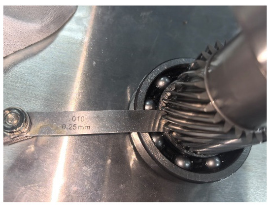
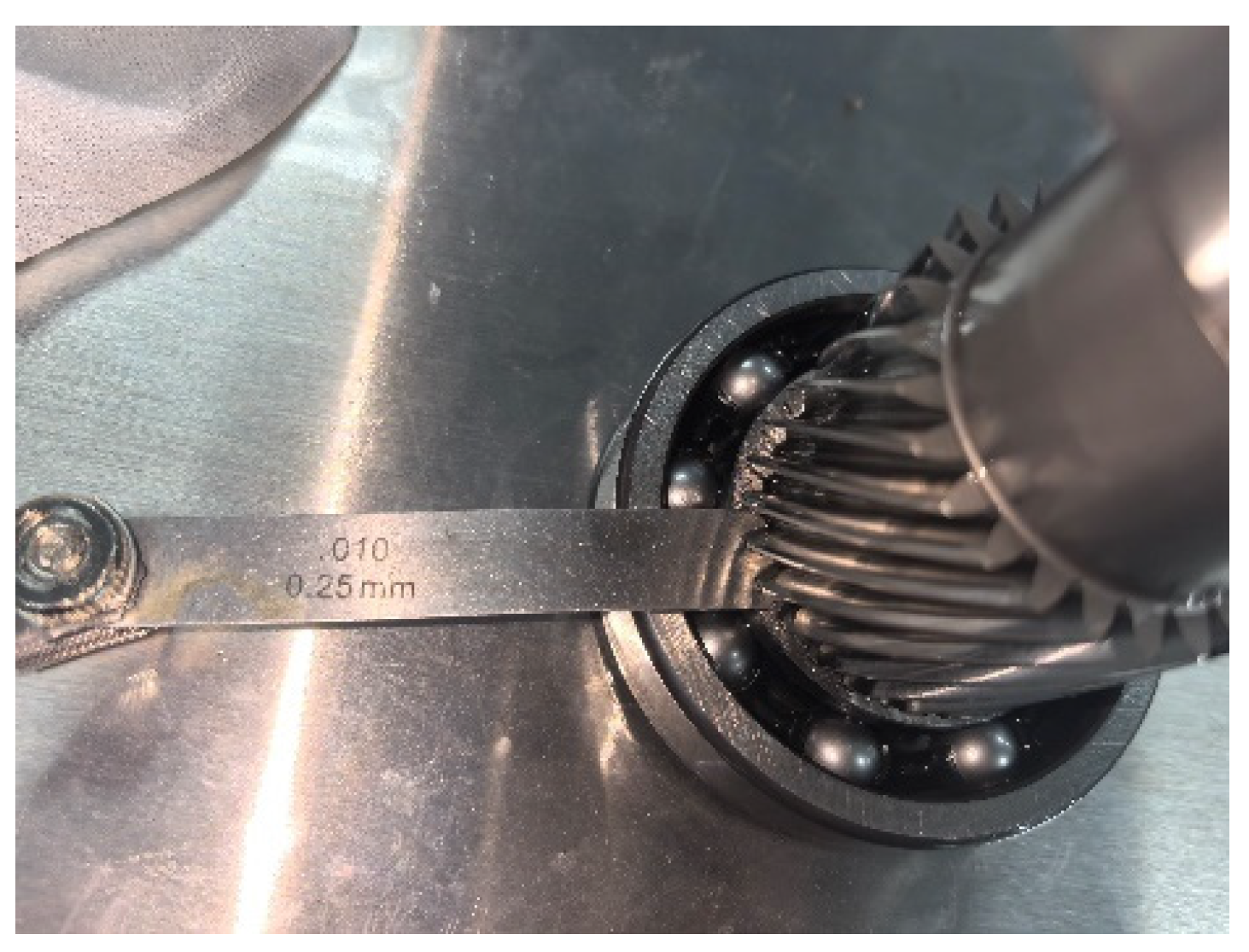
Housing deformation can seriously affect the operational reliability of the overall equipment [17]. Deformation of the bearing mounting holes in the housing can disrupt its design reference dimensions and geometric tolerances, resulting in out-of-tolerance concentricity of the bearing inner and outer rings. This deviation can cause the bearing to bear additional alternating loads and impact stresses during operation, exacerbating the frictional wear between the rolling elements and the raceway and leading to bearing wear failure. At the same time, the interference fit effect between the bearing and the mounting hole will also be weakened [18], reducing the stability of the mating structure and ultimately leading to bearing disengagement failure. Such failures not only seriously affect the transmission performance of the bearing, significantly shortening its service life, but also induce derivative problems such as abnormal vibration and increased noise in the transmission system. In summary, housing deformation is prone to induce multiple cascading failures, leading to abnormal equipment operation.
The bearing disengagement fault is shown in Figure 1.
Figure 1.
Bearing disengagement fault.
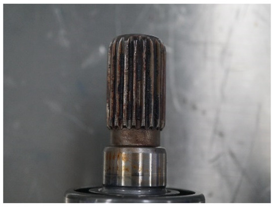
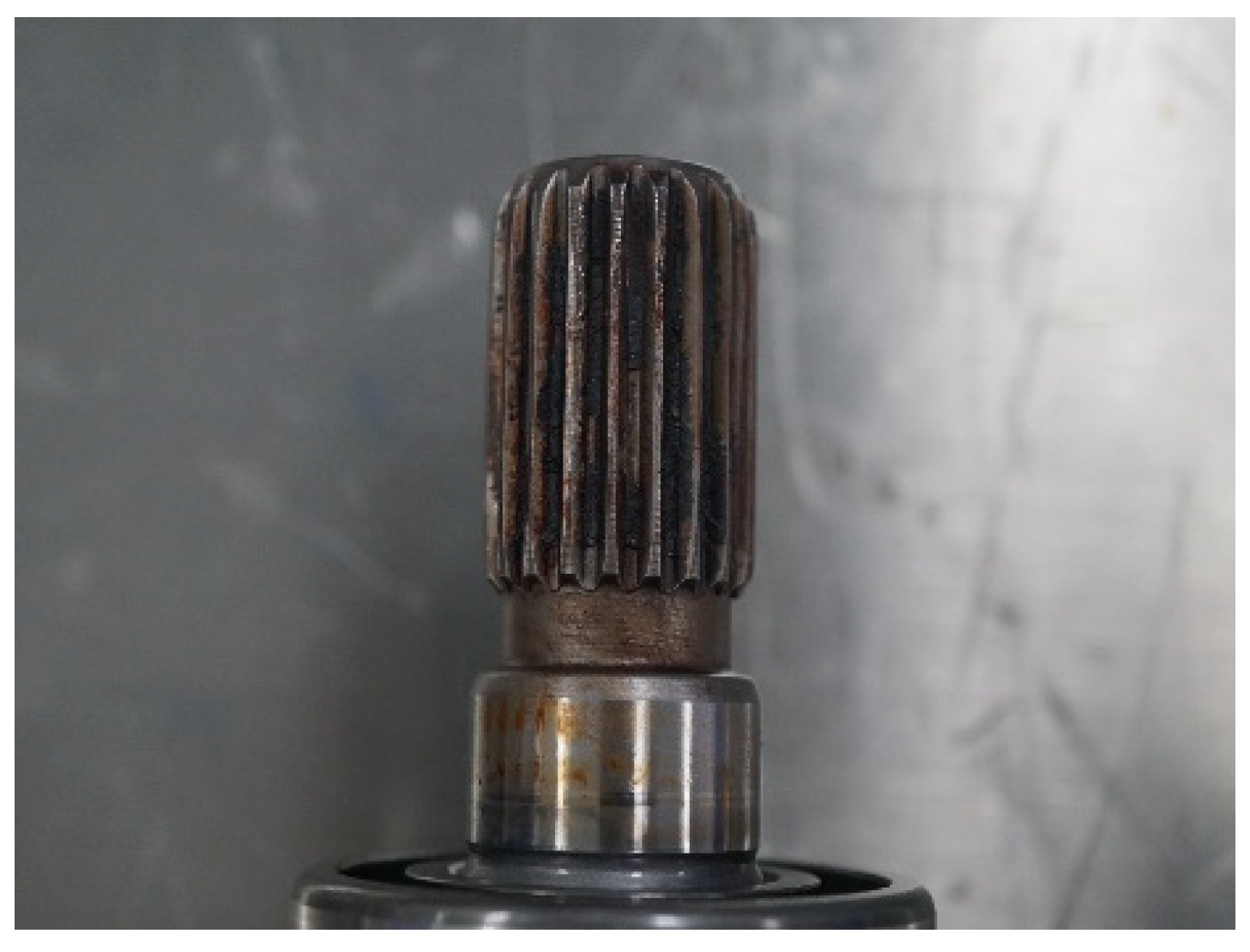
Structural deformation of the electric drive housing will directly damage the internal shafting precision, induce faults with excessive concentricity between the motor shaft and the input shaft, and subsequently trigger a series of cascading structural failures and performance degradation issues. Under the continuous power transmission and alternating load impact, the concentricity deviation will directly exacerbate the abnormal friction and extrusion damage on the spline mating surface, leading to abnormal wear faults.
The wear failure of the spline is shown in Figure 2.
Figure 2.
Spline wear fault.
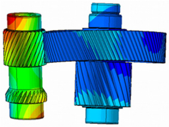
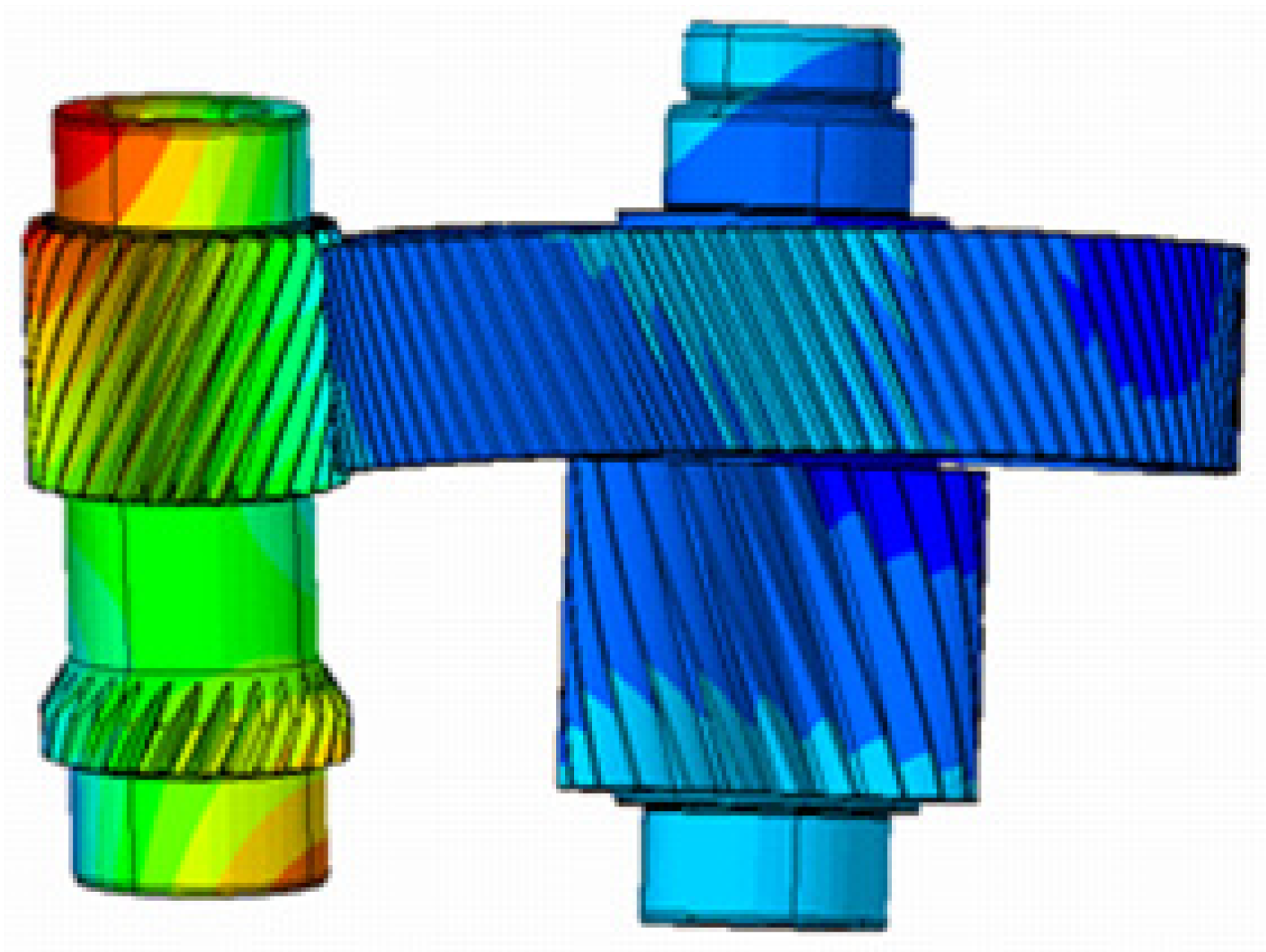
In addition, the asynchronous operation of the shaft system and the misalignment of gear meshing can excite gear whine noise at the same frequency during the power transmission process of the shaft system.
The schematic diagram of gear meshing misalignment is shown in Figure 3.
Figure 3.
Schematic diagram of gear meshing misalignment.
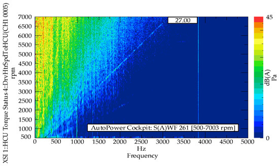
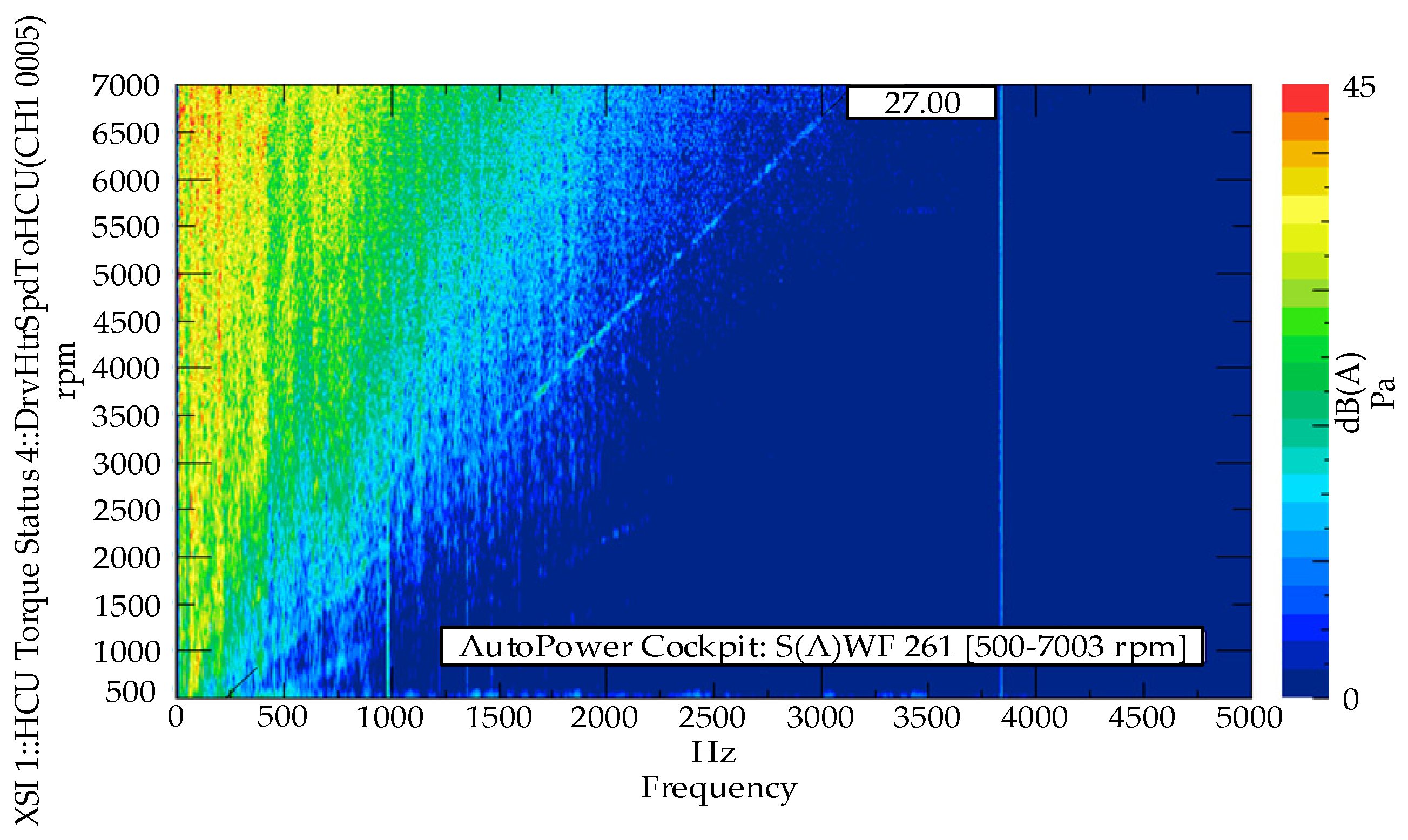
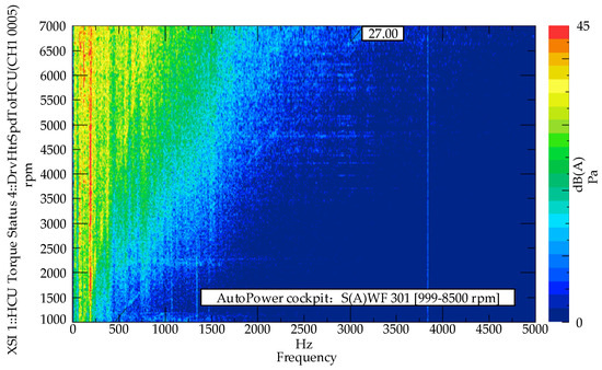
The whistling fault of gear 27 is shown in Figure 4.
Figure 4.
Gear whistling fault at 27th order.
As can be seen from the figure, during the shaft transmission process, there is a 27th-order characteristic whistling noise with the same frequency as the teeth of gear 27. The order noise test curve is evident, proving that the overall level of this order noise is high and the fluctuation amplitude is large. While affecting the driving comfort of the entire vehicle, it is also prone to causing serious transmission failure issues.
3. Finite Element Analysis and Structural Improvement of Electric Drive Housing
3.1. Model Establishment
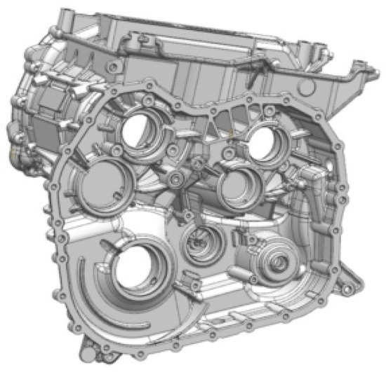
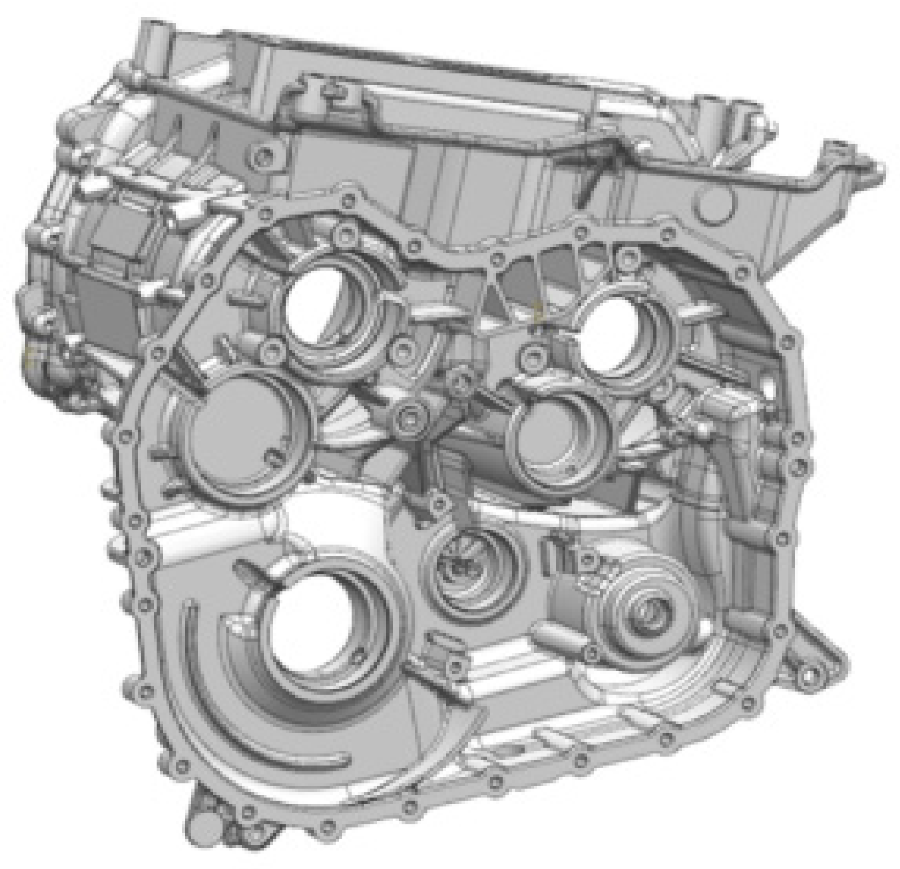
A 3D solid model of the electric drive housing was created using UG (11.0). On the basis of retaining key load-bearing structures and features, the model was processed to weaken non-critical detailed features, making it more suitable for finite element analysis. To achieve consistency between simulation analysis and actual analysis and to minimize neglected factors while maintaining the original structural features of the electric drive system housing, the 3D model was imported into the ABAQUS (2022) finite element simulation software for mesh generation and boundary condition setting.
The UG model is shown in Figure 5.
Figure 5.
UG model of electric drive housing.
The modified model adopted the second-order tetrahedral element C3D10 to complete grid division, the grid size of non-critical areas of the housing was set to 3 mm, and key areas such as bearing holes, suspension holes, and joint surfaces were locally densified with 2 mm grids. The final total number of elements in the model was 1.287818 × 10⁶. To ensure simulation accuracy, convergence verification was conducted on four sets of gradient grids, including a coarse grid with a global size of 4 mm and 4.5 × 10⁵ nodes, a medium grid with a global size of 3 mm and 6.3 × 10⁵ nodes, an optimized grid with a global size of 3 mm, featuring a 2 mm hole area and joint surface densification, and 7.5 × 10⁵ nodes, and a fine grid with a global size of 2 mm, featuring 1 mm hole area densification, and 9.5 × 10⁵ nodes. The comparison results show that the calculation results of the optimized grid and the fine grid were basically consistent, with a maximum stress relative error of less than 0.2% and a maximum deformation displacement relative error of less than 0.15%. Taking into account the calculation accuracy and efficiency, the optimized grid scheme was ultimately selected to meet the requirements of grid convergence. The model material was ADC12 aluminum alloy, with specific material properties including elastic modulus E = 7 × 10¹⁰ Pa, Poisson’s ratio μ = 0.33, yield strength σs = 1.52 × 10⁸ Pa, and density ρ = 2.7 × 10³ Kg/m3. The simulation load and boundary conditions were strictly set according to the actual installation and service conditions. A pre tightening clamping load of 1.6 × 10⁴ N was applied to the connecting bolts, and a suspension load was applied at the coupling point of the suspension hole; the working surfaces of each bearing hole were coupled to the corresponding geometric center reference point, the bearing load was calculated based on the radial force, axial force, and tangential force corresponding to the maximum torque of the electric drive assembly, and this was applied to the center of the bearing hole in the normal compression direction along the bolt axis. In terms of boundary constraints, full degree of freedom fixed constraints were applied to the engine installation contact surface, and the suspension hole and bearing inner hole surfaces were coupled to their respective center reference points. Binding constraints were used on the housing joint surface and connecting bolts to limit all degrees of freedom of the housing and frame connecting bolt holes. At the same time, a uniform self-weight load was applied to the motor installation end face to accurately restore the actual stress and stress state of the housing.
The magnitude and direction of bearing force are shown in Table 2.
Table 2.
Bearing force magnitude and direction.
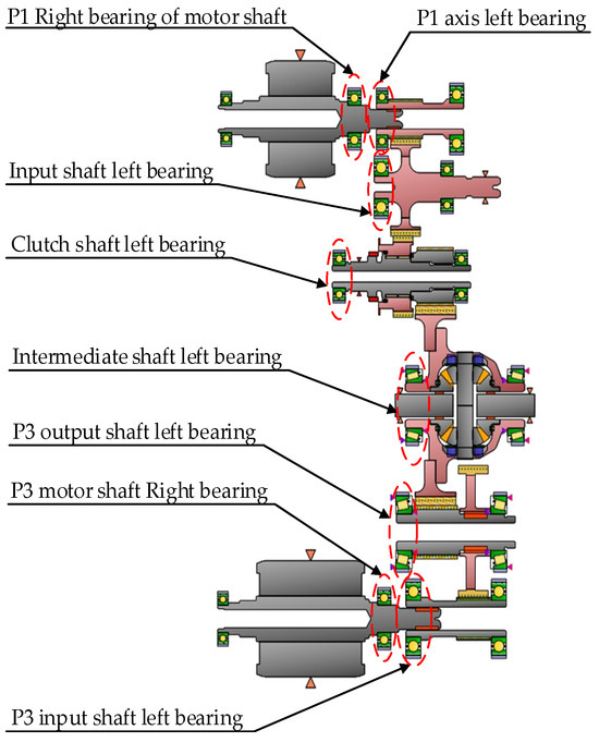
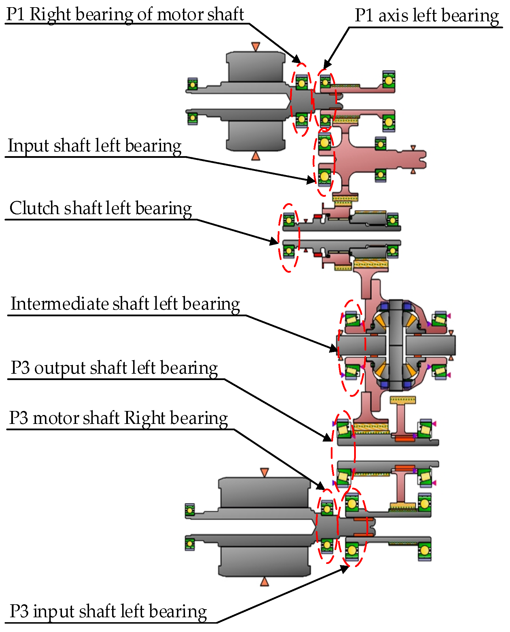
The bearing holes of the drive housing are shown in Figure 6.
Figure 6.
Bearing holes of the drive housing.
The deformation data of each bearing hole before improvement are shown in Table 3.
Table 3.
Deformation data of bearing holes before improvement.
As can be seen from the table, the horizontal, vertical, normal, and total three-dimensional deformation of each bearing hole before improvement are all relatively large. The maximum unidirectional deformation at a single measuring point is close to 0.1 mm. Among them, the total three-dimensional deformation of the P3 intermediate shaft and the left bearing of the output shaft is most prominent, with values exceeding 0.15 mm, far exceeding the safety tolerance range. Excessive structural deformation is extremely prone to cause bearing eccentricity and out-of-roundness, as well as excessive shaft concentricity, which, in turn, leads to faults such as poor gear meshing, operational whistling vibration, abnormal wear of splines, etc. In severe cases, it can damage transmission components, resulting in the failure of the entire electric drive system.
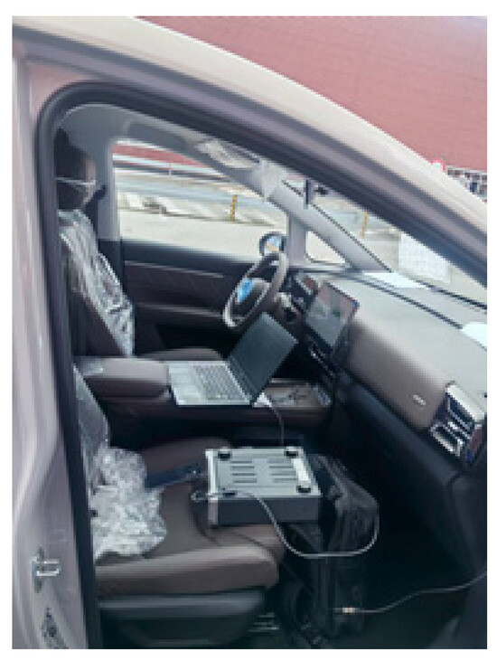
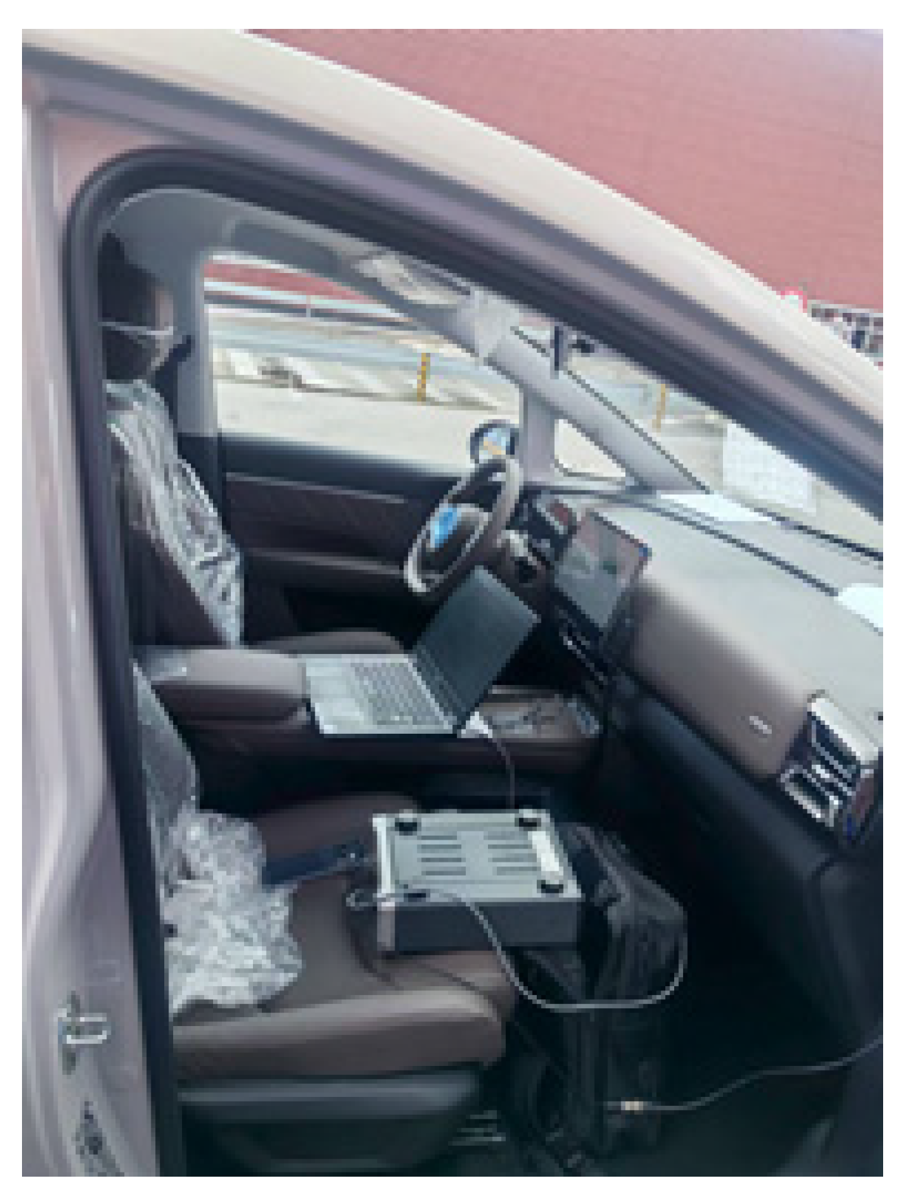
The order analysis is based on the P3 axis, and the driving gear has a total of 27 teeth. The whistling caused by tooth surface meshing is defined as the 27th order. In actual testing, vehicle sampling is used and a microphone is placed next to the driver’s ear. Combined with a multi-channel data acquisition system (Siemens LMS SCADA), high-resolution P3 axis velocity signals are collected through encoders to achieve high-precision synchronous acquisition with sampling frequencies above 25 kHz and dynamic ranges above 100 dB. The order spectra of sound pressure and rotational speed are obtained through Fourier transform.
The data collection system is shown in Figure 7.
Figure 7.
Data acquisition system.
The simulated fault occurred under normal operating conditions, with low-frequency cyclic load characteristics and no significant inertial impact or resonance effects. The dynamic amplification effect can be ignored. Therefore, this article adopts static stress simulation to conduct simulation analysis. This method replaces the actual alternating cyclic load with the maximum equivalent static load and obtains the stress distribution in key areas of the housing through static simulation to characterize the stress level under low-frequency alternating working conditions. However, its limitation lies in the neglect of micro motion damage and load phase coupling effects caused by small vibrations, and it is only applicable to low-frequency, resonance free, and impact free steady-state cyclic operating conditions. The working conditions of this study meet the above prerequisites; therefore, the equivalent method has engineering feasibility.
3.2. Strain–Stress Analysis
The stress distribution of the housing under load conditions is shown in Figure 8.
Figure 8.
Stress distribution contour plot.
As can be seen from the figure, the stress concentration areas of the housing are relatively fixed, mainly concentrated in three key locations: the transition area between the motor bearing seat and the housing side wall, the root of the reinforcing rib of the reducer bearing seat, and the surrounding area of the bolt connection holes. Under dynamic load, the maximum stress values in the above areas approach the yield strength of ADC12 aluminum alloy, making the structure prone to deformation, cracking, and other hidden dangers. The stress concentration problem of the housing mentioned above is mainly due to the sudden change in load transfer path during the loading process of the housing, which leads to abnormal superposition of local stress and increases the risk of structural failure.
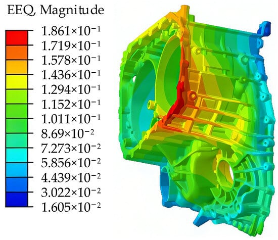
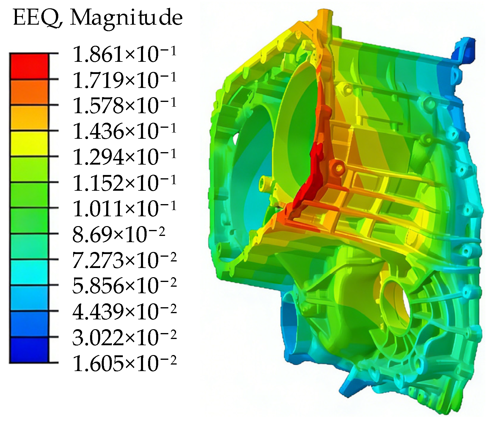
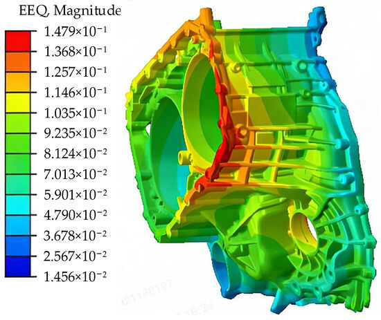
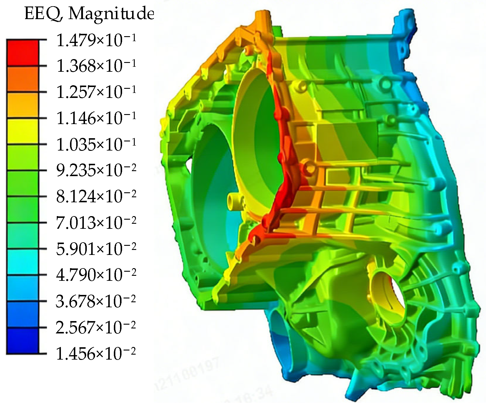
The equivalent total strain distribution of the housing is shown in Figure 9.
Figure 9.
Contour plot of equivalent total strain distribution.
According to the analysis of the stress test results, the equivalent total strain of the housing is highly consistent with the stress distribution characteristics. The distribution characteristics of the equivalent total strain are shown in Figure 9. From the perspective of the load effect, due to the conduction and accumulation of dynamic torsional loads along the housing structure, the maximum strain concentration area appears at the top of the motor bearing seat. Actual measurements confirm that the deformation in this area exceeds the maximum allowable value specified in the design, becoming a key factor causing local structural deformation of the housing, which, in turn, leads to fatigue failure and cascading transmission failure, directly threatening the long-term stable operation of the power transmission system. Except for the high-risk critical zone mentioned above, the strain values of other components and transition zones of the housing are stably controlled below 1.2 × 10³, and the corresponding deformation fully meets the design permit requirements. The dimensional stability and structural stress state are good, not exceeding the safe design range.
Based on the simulation analysis results of the stress and strain distribution contour maps of the integrated housing, it can be concluded that the transition area of the motor bearing seat is the core weak link of the entire housing. The stress level in this area approaches the yield limit of ADC12 aluminum alloy, and the structural deformation exceeds the design allowable value. Long-term use is highly prone to issues such as transmission accuracy degradation, fatigue cracking, and failure. Therefore, it needs to be listed as a key improvement target for this structural improvement.
3.3. Structural Improvements
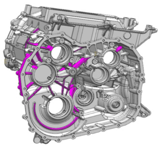
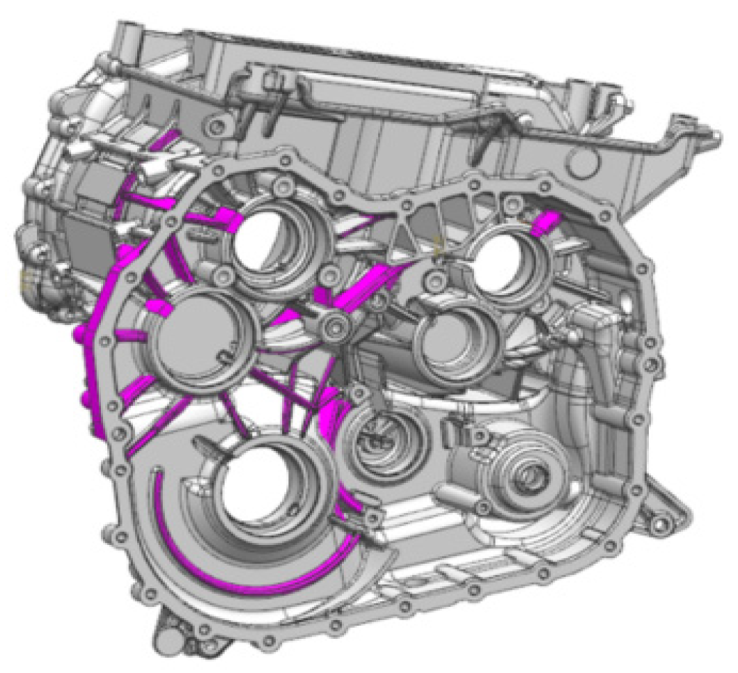
Based on the results of the CAE analysis and fault tracing, the following improvement plan is proposed from the perspective of enhancing structural rigidity and improving the load transfer path: improve the ribs in weak areas, add reinforcement ribs to the bearing seat, extend the reinforcement ribs to the joint surface, connect the reinforcement ribs end-to-end to form an integral framework, arrange the main reinforcement ribs along the main loading direction of the housing (torque transfer path, radiation direction at the bearing installation location), ensure the thickness matches the housing matrix, and form a main load-bearing structure resistant to torsion and bending. At the same time, add auxiliary ribs in the thin-walled areas of the housing and stress-concentrated corners (around the oil passage holes and at the root of bolt installation bosses) to avoid local deformation or cracking, improve the load transfer path, and simultaneously improve the die-casting process performance of the housing.
The improved housing model is shown in Figure 10.
Figure 10.
Schematic diagram of housing improvement.
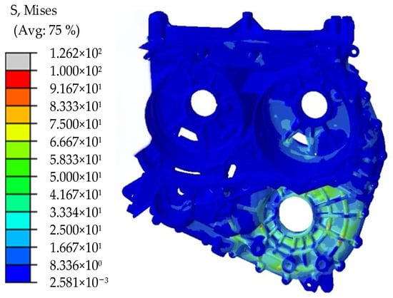
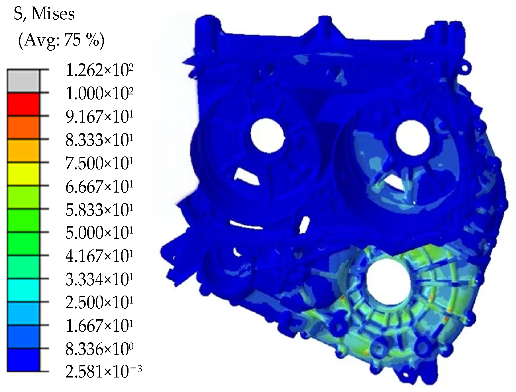
To visually verify the improvement effect of the structural improvement scheme on mechanical properties, a loading stress–strain test was conducted on the improved electric drive housing. The test adopted a scheme, parameters, and testing process completely consistent with the original housing to ensure the comparability of the test results. The test results are shown in Figure 11. Through comparative analysis of the test data, it was found that the maximum stress value in the transition area of the motor bearing seat of the improved housing decreased significantly by 40.6% compared to the original housing, the maximum strain value dropped to 1.15 × 10⁻³, and the corresponding maximum deformation decreased by 42.7% compared to the original housing. All indicators met the design requirements, and the overall structural rigidity of the housing was significantly improved, with a substantial improvement in the stress state.
Figure 11.
Simulated image of the improved housing.
The improved housing simulation is shown in Figure 11.
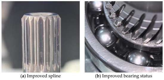
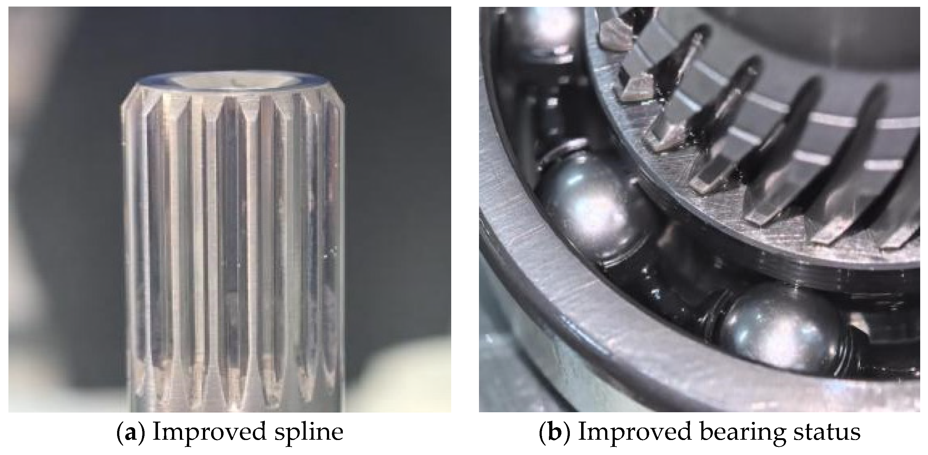
The improved housing was verified according to the durability test specification for hybrid transmission assemblies. The test employed variable load cycling conditions to simulate the complex load impacts encountered during actual vehicle operation. After continuous operation for 750 h, the housing was inspected. The concentricity error of the bearing mounting holes was controlled within the allowable range, and the supporting bearings and splines operated stably without any obvious abnormalities such as wear, pitting, creep displacement, etc. The sealing surface showed no lubricant leakage, indicating good sealing performance, and there was no noticeable step noise during operation. The deformation of each bearing mounting hole in the housing also improved significantly after modification, demonstrating outstanding deformation control compared to the pre-modification state.
The improved spline and bearing status are shown in Figure 12.
Figure 12.
Improved spline and bearing status.
The deformation data of each bearing hole after deformation are shown in Table 4.
Table 4.
Deformation data of each bearing hole after improvement.
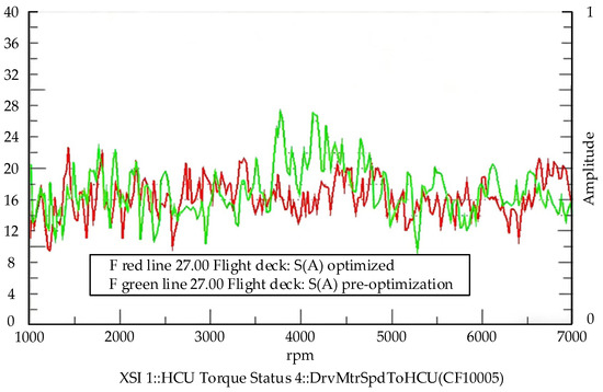
As can be seen from the table, after performance testing and noise vibration testing, it is verified that the stability of power transmission in the improved electric drive housing shaft system is significantly enhanced. The horizontal, vertical, normal, and total deformation in all bearing holes are significantly reduced, with the maximum deformation at a single measuring point in one direction dropping to 0.08 mm. The most prominent deformation before improvement, specifically in the left bearing of the P3 intermediate shaft, decreases to 0.09 mm in total deformation in three directions, a reduction of about 42.7%. This significant reduction greatly mitigates the risks of malfunctions such as poor gear meshing, operational whistling vibration, and abnormal wear of the spline, which are caused by bearing eccentricity and out-of-roundness, as well as excessive shaft concentricity. In the original shaft transmission process, the 27th-order whistling issue with the same frequency as the gear 27 teeth is significantly improved compared to before improvement. The specific noise reduction effect and the variation pattern of order noise are shown in Figure 13, and the comparison of orders before and after improvement is shown in Figure 14.
Figure 13.
Improved gear whine state at 27th order.
Figure 14.
Comparison of orders before and after improvement.
According to the comparison curve of the 27th-order whistling before and after improvement, it can be clearly seen that the 27th-order meshing whistling of the shaft transmission system is significantly weakened and the overall noise level is significantly reduced. Before optimization, a significant peak of the 27th-order whistling appears in the range of 3500–5000 rpm, with the highest amplitude close to 28 dB, and the curve fluctuates violently; the optimized whistling peak is effectively suppressed, with the highest amplitude reduced to about 23 dB. The overall curve tends to be smooth without obvious peaks, and the overall operating noise of the machine is significantly reduced.
The improved housing has stable support stiffness, the concentricity of the motor shaft and the input shaft is controlled within the design tolerance range, the gear mesh clearance is uniform, the mesh accuracy remains stable and shows no significant degradation, and the equipment operates smoothly throughout the entire process without issues such as excessive vibration, addressing the original fault hazards. In addition, we compare the deformation of the motor back cover housing before and after improvement.
The deformation amounts of the housing before and after improvement are shown in Table 5.
Table 5.
Comparison of deformation of motor back cover housing before and after improvement.
From the table, it can be seen that the deformation of each measuring point on the motor back cover housing before improvement is generally large. The deformation of the positioning pin on the motor back cover exceeds 0.06 mm, which is close to the safety threshold. In actual working conditions, this is highly likely to cause housing failure and related faults. After the structural improvement of the motor back cover housing, the deformation of each measuring point on the housing is significantly decreased. Among them, the deformation improvement of the positioning pin position on the motor back cover housing exceeds 0.05 mm, and the deformation control effect is outstanding. The comparison results fully demonstrate that the housing improvement scheme can effectively suppress structural deformation and have a significant effect on improving housing stiffness and structural stability.
In addition, the improved electric drive housing was mounted on a complete vehicle for long-distance road testing verification. The vehicle accumulated a total mileage of 6 × 10⁴ km, covering various typical operating conditions such as flat and straight roads, bumpy roads, and slopes. The test proved that the housing had no structural deformation, cracking, sealing leakage, or other issues. The internal shafting, bearings, and gear components showed no abnormal wear or loosening, and no faults occurred. This fully verified that the housing structure improvement scheme proposed in this paper possesses excellent engineering feasibility and long-term reliability, which can effectively ensure the stable operation of the electric drive system.
4. Experimental Verification
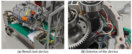
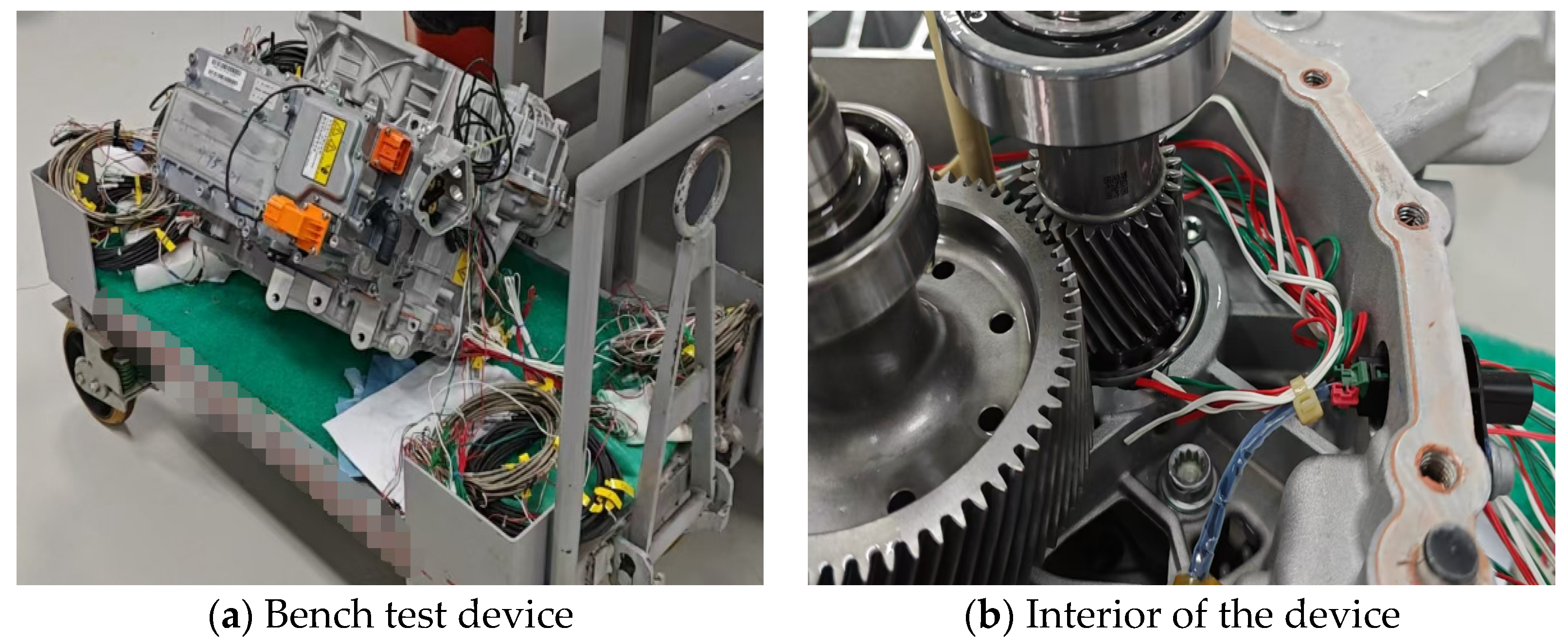
To verify the accuracy of the CAE simulation model, bench tests were conducted on the loading of the electric drive housing. Strain gauges were installed on the back of the housing bearing seat and the ribs supporting the bearing seat. The maximum torque of the gearbox was applied, and the stress values of the stress points around the housing bearing seat were statically measured. The data acquisition equipment used Simcenter SCADAS XS (handheld), which contains 6 or 12 channels, with a sampling frequency of up to 5 × 10⁴ Hz for each channel, meeting most NVH analysis requirements. The measurement accuracy was 24-bit ADC resolution.
The bench test is shown in Figure 15.
Figure 15.
Rack test of load deformation of drive housing.
To ensure the reliability of the experimental data, each set of experiments was repeated three times, and the arithmetic mean was taken as the final experimental result. The actual measured data from the deformation experiment was compared with the simulation results. The specific comparison data is shown in Table 6.
Table 6.
Comparison of simulation and experimental data of housing stress values.
As can be seen from the table, the relative errors between the experimentally measured results and the simulation calculations of the stress values at each measuring point range from 2.1% to 5.1%, all of which are less than the allowable error value of 10%. This fully demonstrates that the housing finite element model established this time has high accuracy and can be used for subsequent structural simulation analysis and improvement research.
5. Conclusions
A finite element model of the electric drive housing for pure electric passenger vehicles was established. The strain and stress of the housing under rated load were analyzed, and its deformation pattern under load was studied. Improvement plans were proposed for structurally weak areas. Finally, tests were conducted on a load deformation rig, and the main conclusions are as follows:
(1) The transition zone of the motor bearing housing is a structural weak point of the electric drive housing. The maximum stress in this area is close to the yield strength, and the maximum structural deformation exceeds the design allowable value, posing risks such as reduced accuracy, deformation, and cracking.
(2) The structural rigidity of the housing is improved, with rib enhancements made in the thin-walled area of the housing. As a result, the maximum stress–strain values and deformation of the housing are significantly reduced, ensuring stable operation of the supporting components and no lubricant leakage from the sealing surface.
(3) After improving the load transfer path of the bearing housing, the stability of power transmission in the housing shaft system is enhanced, the deformation of each bearing hole is significantly reduced, the gear meshing accuracy is stable without any whistling issues, and the incidence of housing failures approaches zero.
Author Contributions
Writing—original draft, methodology, conceptualization, X.L.; validation, formal analysis, data curation, Y.B.; investigation, data curation, L.L.; writing—original draft, data curation, Y.Q.; writing—review and editing, visualization, funding acquisition, Y.H.; integration of all items, R.W.; project coordination and achievement integration, X.F. All authors have read and agreed to the published version of the manuscript.
Funding
This research was supported by the Guangxi Science and Technology Major Program (No. Gui Ke AA23062058) and the Guangxi Science and Technology Program (No. Gui Ke AD23026183).
Data Availability Statement
The original contributions presented in this study are included in the article. Further inquiries can be directed to the corresponding author.
Conflicts of Interest
Authors Xing Liu, Lijuan Liu, Yunde Qin, Yong Huang and Ruixue Wang were employed by the company Liuzhou Saike Technology Development Co., Ltd. The remaining authors do not have any conflicts of interest with other entities or researchers.
References
- Ning, Z.; Jiang, J.; Yang, H. Power loss and splash lubrication flow field characteristics in the electric drive reduction system of commercial vehicles. J. Braz. Soc. Mech. Sci. Eng. 2026, 48, 224. [Google Scholar] [CrossRef] [Scilit]
- Li, S.; Zuo, S.; Yin, B.; Jin, M.; Li, H.; Liu, C.; Shi, L. A new method for analyzing gearbox vibration and noise in electric drive systems based on different modal forms. J. Vib. Control 2025, 32, 2446–2460. [Google Scholar] [CrossRef] [Scilit]
- Bai, N.; Jiao, A.; Liu, S. Finite element analysis of drive axle housing with ANSYS Workbench. Appl. Mech. Mater. 2012, 215, 717–720. [Google Scholar] [CrossRef] [Scilit]
- Fu, J.; Wang, J.; Wang, J. Finite Element Analysis and Structure Optimization on Light-Duty Truck Driving Axle Housing. Appl. Mech. Mater. 2010, 37, 482–485. [Google Scholar] [CrossRef] [Scilit]
- Zhang, T.; Wang, H.; Yang, Q. Research on the Lightweight Drive Axle Housing of Electric Farm Management Machine. Mechanics 2024, 30, 531–538. [Google Scholar] [CrossRef] [Scilit]
- Jin, D.; Wang, Z.; Wang, J. Lightweight design and optimization of three-speed electric drive axle. IOP Conf. Ser. Earth Environ. Sci. 2020, 546, 052005. [Google Scholar] [CrossRef] [Scilit]
- Liu, Y.; Liu, C.; Tan, J.; He, Y. Lightweight design based on automotive drive axle housing. PLoS ONE 2025, 20, e0331300. [Google Scholar] [CrossRef] [Scilit] [PubMed]
- Chen, Y.; Liu, X.; Shan, Y.; He, T. Lightweight design of drive axle housing based on reliability. Int. J. Veh. Perform. 2020, 6, 294–309. [Google Scholar] [CrossRef] [Scilit]
- Zhang, Y.; Kong, L.; Shi, J. Structural Analysis and Optimization of Electric Scraper Drive Axle Housing under Multi-Load. Appl. Mech. Mater. 2014, 496, 1152–1156. [Google Scholar] [CrossRef] [Scilit]
- Mi, C.; Li, Y.; Liu, X.; Hu, X. An energy-based anti-fatigue optimization design method of welded rear axle housing in a mining dump truck. Mechanics 2023, 29, 317–323. [Google Scholar] [CrossRef] [Scilit]
- Pan, Y.; Du, S.; Song, J.; Wu, C.; Liao, L. Research on welding residual stress and deformation of drive axle housing based on SYSWELD. J. Phys. Conf. Ser. 2026, 3174, 012094. [Google Scholar] [CrossRef] [Scilit]
- Pan, Y.; He, L.; Zhang, W.; Wu, C.; Liao, L. Sensitivity analysis of forming parameters of high-strength 610l steel drive axle housing to springback. J. Phys. Conf. Ser. 2025, 3126, 012039. [Google Scholar] [CrossRef] [Scilit]
- Dai, Y.; Ji, J.; Luo, L. Simulation Study on Hot Stamping Forming of the Drive Axle Housing of Heavy Truck. IOP Conf. Ser. Mater. Sci. Eng. 2018, 301, 012047. [Google Scholar] [CrossRef] [Scilit]
- Xu, C.; Li, P.; Guo, Y.; Zeng, J.; Jin, H. Analysis and experimental study on compound mechanical bulging process for medium-sized vehicle drive axle housing. Procedia Eng. 2017, 207, 1737–1742. [Google Scholar] [CrossRef] [Scilit]
- Meng, X.; Zhang, Y.; Ding, R.; Liu, W.; Wang, R. Research on Unbalanced Electromagnetic Force Under Static Eccentricity of the Wheel Hub Motor Based on BP Neural Network. World Electr. Veh. J. 2025, 16, 252. [Google Scholar] [CrossRef] [Scilit]
- Peng, Z.; Chen, W.; Liu, J.; Zhu, L.; Wei, D. Fatigue life sensitivity research for electric driving system in driving load cases and random vibration load cases. Proc. Inst. Mech. Eng. 2025, 239, 4418–4430. [Google Scholar] [CrossRef] [Scilit]
- Singh, R.; Nalawade, A.; Pande, M.; Singh, P. Vibration and noise characteristics of an inverter for electric vehicle application. Vibroeng. Procedia 2023, 50, 145–151. [Google Scholar] [CrossRef] [Scilit]
- Zou, D.; Yu, H.; Zhou, P.; Wang, Z.; Li, D. Influence of Interference Fit on Dynamic Characteristics of TBM Cutter Bearing. J. Eng. 2025, 2025, 8888717. [Google Scholar] [CrossRef] [Scilit]

Disclaimer/Publisher’s Note: The statements, opinions and data contained in all publications are solely those of the individual author(s) and contributor(s) and not of MDPI and/or the editor(s). MDPI and/or the editor(s) disclaim responsibility for any injury to people or property resulting from any ideas, methods, instructions or products referred to in the content. |
© 2026 by the authors. Licensee MDPI, Basel, Switzerland. This article is an open access article distributed under the terms and conditions of the Creative Commons Attribution (CC BY) license.