


Abstract
Based on urban subway foundation pit projects in typical limestone areas, this paper employs 3DEC numerical simulation to investigate the effects of the thickness and burial depth of weak interlayers on the deformation characteristics and stability of the dip slope and anti-dip sides of rock foundation pits. The results reveal asymmetric deformation responses between the two slope types. The anti-dip side undergoes bending and toppling deformation; the displacement within the weak interlayer is greater than that of the overlying rock mass, and the spatial position of the weak interlayer governs the maximum deformation of the anti-dip side. In comparison, the thickness and burial depth of the weak interlayer exert a significant influence on the horizontal displacement of the dip slope side. Two quantitative critical thresholds are identified: (1) an interlayer thickness threshold—when t ≥ 4 m, the extrusion displacement of the weak interlayer is distinctly larger than that of the adjacent hard rock, while t ≤ 3 m shows no obvious displacement difference due to the clamping effect of surrounding rock—and (2) a burial depth threshold—slope displacement rises sharply when interlayer burial depth reaches 22.66~26.15 m, while shallow-buried interlayers (12.20~19.18 m) only cause limited deformation. Additionally, the existence of weak interlayers leads to substantially larger displacement in the upper hard rock stratum relative to the lower stratum. These findings provide a reliable reference for the supporting optimization and stability design of rock foundation pits.
1. Introduction
Bedded rocks are widely distributed in nature. Excavation of foundation pits in bedded rock masses typically results in the formation of a dip slope side and an anti-dip slope side [1]. Generally, the anti-dip slope side exhibits better stability. Nevertheless, both sides are prone to slope instability of different modes when the rock mass has a steep dip angle and poor integrity—for instance, the dip slope side is susceptible to sliding along the structural planes of the rock mass [2,3], while the anti-dip slope side may suffer local collapse and toppling failure [4,5]. Oversimplifying rock foundation pits as soil ones often leads to an overestimation of their stability.
The deformation characteristics of bedding-parallel slopes are influenced by a variety of factors [6,7]: the deformation and failure modes of such slopes are primarily governed by internal factors, while external triggering factors mainly activate or exacerbate slope deformation and failure by inducing changes in these internal factors [8]. The basic deformation modes of bedding-parallel slopes mainly include sliding–cracking and sliding–bending [9,10].
When the slope angle is steeper than the rock stratum dip angle, the weak structural planes or weak layers of the slope become exposed at the leading edge. Their anti-sliding resistance is insufficient to counteract the downslope shear force of the overlying rock mass, and a tensile crack surface forms at the trailing edge under tensile stress, causing the slope mass to slide downwards. Notably, bedding-parallel sliding failure may also occur when the rock stratum dip angle is steep [11].
In rock foundation pit engineering, dip and anti-dip slopes typically coexist and interact with each other. For comparative studies on these two types of slopes, scholars at home and abroad have mainly adopted theoretical analysis and numerical simulation methods. By analyzing the differences in response characteristics between bedded dip and anti-dip slopes under identical conditions, they have investigated the distinct deformation laws of the two slope types [12,13,14,15,16].
In summary, the current research on layered rock slopes mainly focuses on fields such as highways [17,18] and water conservancy projects [19,20], with insufficient comparative research on dip slopes and anti-dip slopes, particularly regarding their deformation laws. Compared with general excavated dip and anti-dip slopes, foundation pits are completely formed by artificial excavation; in addition, the slope angle of foundation pits is nearly 90°. For high-dip rock formations, both dip and anti-dip sides have low stability [21]. Moreover, current foundation pit support design theories and specifications are primarily based on extensive research and engineering practice of soil foundation pits, and their applicability to rock foundation pits—particularly those in layered rock with weak interlayers—remains inadequate, leading to a lack of reliable theoretical basis for the support design and optimization of rock foundation pits.
It should be emphasized that the dip slope and anti-dip sides of layered rock foundation pits exhibit fundamentally different failure modes. The dip slope side is predominantly susceptible to planar sliding along the bedding-parallel structural planes under the shear stress from the overlying rock mass, where the weak interlayer directly controls the horizontal displacement. In contrast, the anti-dip slope side is primarily governed by bending-tensile toppling failure, where the rock layers bend and topple outward under gravitational loading, and the weak interlayer only causes local displacement peaks without fundamentally altering the overall toppling deformation trend. These two fundamentally different deformation mechanisms necessitate differentiated support design strategies.
Accordingly, taking the deep foundation pit of Nansanhuan Station on Xuzhou Metro Line 3 as the engineering background—a typical steeply dipping layered limestone deep excavation in Jiangsu Province, China, where near-vertical dip slope and anti-dip cut slopes coexist with locally developed weak interlayers in the rock mass—this study employs the “Three-Dimensional Distinct Element Code” (3DEC) for numerical simulation to investigate the asymmetric deformation responses and underlying failure mechanisms of the two slope types. The analysis accounts for variations in weak interlayer occurrence (including thickness and burial depth), as well as the mechanical parameters of rock masses and weak strata, to provide a targeted theoretical basis and engineering reference for support optimization and stability design of similar steeply dipping layered rock foundation pits. The critical thresholds identified in this study can directly inform support design optimization for rock foundation pits in limestone areas, particularly in urban subway construction where high-dip layered rock conditions are frequently encountered.
2. Materials and Methods
2.1. Basic Assumptions
During numerical simulation, key research objects are retained while secondary components are neglected to achieve reasonable model simplification without compromising scientific validity, with the simplification assumptions listed as follows: thin overlying soil layers at the pit site (typically less than 2 m thick) are ignored to treat the project as an entirely rock-based foundation pit, a simplification supported by site geological survey data showing the thin Quaternary overburden has negligible influence on deep rock slope deformation; the strike of rock strata on pit slopes is set parallel to the longitudinal axis of the foundation pit with an intersection angle of 0°, meaning the two pit sides represent ideal dip slope and anti-dip sides, respectively, which approximates the field-measured intersection angle of less than 5° between stratum strike and the pit axis for controlled comparative study; the impacts of surrounding buildings, surface surcharges, and tectonic movements are excluded, as no important structures exist within twice the excavation depth, no large fixed surcharge is applied during construction, and no active faults develop in the study area, so as to eliminate accidental external interference and focus on the inherent deformation laws of excavated slopes; and rock mass structural planes are assumed straight and distributed in parallel with uniform spacing, in accordance with the layered rock mass generalization method specified in Standard for engineering classification of rock mass (GB/T 50218-2014; China Planning Press: Beijing, China, 2014) [22] and field survey results showing that site limestone joints are generally straight with small spacing differences, which is consistent with conventional structural plane settings for steeply dipping layered rock simulations.
2.2. Establishment of the Numerical Model
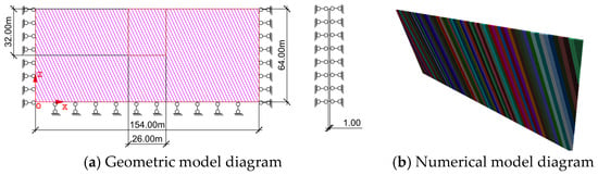
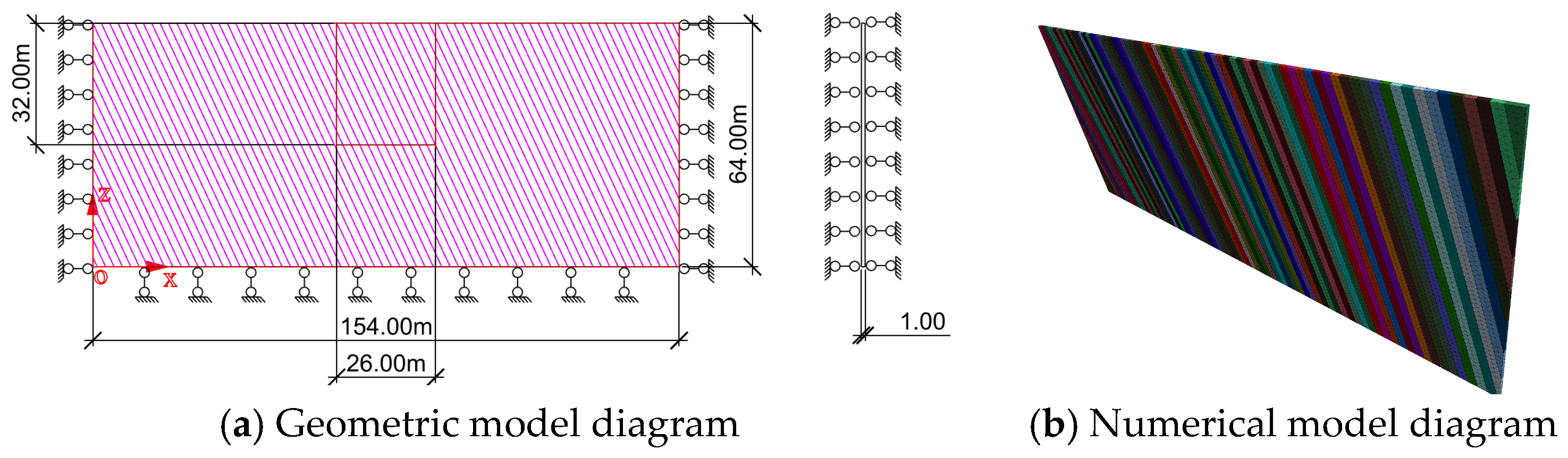
To eliminate boundary effects, a plane strain model (unit length taken in the longitudinal direction) is adopted to study the deformation laws and stability of the dip and anti-dip slopes of the transfer section foundation pit. For a typical three-story subway foundation pit project in central and western China, through trial calculation and analysis, the model size is determined as 154 m × 1 m × 64 m.
2.3. Boundary Conditions
Since node velocity serves as the primary variable in the 3DEC (Version 7.0, Itasca Consulting Group, Inc., Minneapolis, MN, USA) software, boundary conditions are defined based on velocity criteria. Displacement restraints are assigned to five surfaces of the 3D model excluding the top surface to restrict directional movement, corresponding to zero nodal velocity in the constrained directions, as illustrated in Figure 1a,b. Specifically, the model’s displacement boundaries are configured such that the nodal horizontal velocity on the two X-direction lateral faces is fixed at 0; the nodal velocity on the two Y-direction lateral faces is fixed at 0; all three velocity components of nodes on the bottom base are set to 0 to form a fully constrained boundary; and the top surface is defined as a free boundary without any displacement limitations.
Figure 1.
Geometric modeling diagram and numerical model diagram for numerical simulation.
2.4. Constitutive Model and Parameter Selection
In this study, the widely validated ideal elastoplastic constitutive model, in conjunction with the Mohr–Coulomb yield criterion, is employed for all numerical simulations. Compared with more complex constitutive alternatives, the Mohr–Coulomb model requires fewer input parameters that are readily obtained from routine geotechnical tests, is built on a clear and physically intuitive conceptual basis, and can reliably capture the frictional shear strength behavior of rock and soil masses. These practical and theoretical merits have made it a well-established, extensively adopted choice for numerical investigations of excavations in layered rock formations.
Three-Dimensional Distinct Element Code (3DEC) is a numerical analysis program based on the distinct element method, designed to characterize the mechanical behavior of discontinuous media. It adopts the same finite difference calculation scheme as FLAC, with enhanced functions to simulate the discontinuous mechanical behavior of interfaces, thus equipping the software with robust general analysis capabilities for both continuous and discontinuous medium mechanics problems. In this study, rock mass structural planes are classified into hard structural planes and weak structural planes according to their cementation and filling conditions: the former are simulated using the thickness-free contact elements provided by 3DEC, while the latter are modeled with solid elements.
The material parameters required for 3DEC numerical simulation include solid elements (density, bulk modulus, shear modulus, cohesion, internal friction angle, and tensile strength) and contact surface elements (internal friction angle, cohesion, tensile stiffness, normal stiffness, and tangential stiffness). Generally, the engineering geological survey provides the elastic modulus and Poisson’s ratio of rock and soil. Therefore, it is necessary to convert the elastic modulus E and Poisson’s ratio μ into bulk modulus K and shear modulus G. Their conversion formulas are shown in Equations (1) and (2).
When sliding or opening is allowed for the contact surface element, the normal stiffness and tangential stiffness are slightly less important than other parameters. In the absence of measured data, they can be taken as 10 times the equivalent stiffness of the “hardest” adjacent surrounding area, as shown in Equation (3):
where
- is the normal stiffness, Pa, and is the tangential stiffness, Pa;
- is the bulk modulus, Pa, and is the shear modulus, Pa;
- is the minimum dimension of the connecting region along the normal direction of the contact surface.
The physical and mechanical parameters of rock mainly include density, elastic modulus, Poisson’s ratio, internal friction angle, cohesion, and tensile strength of rock. The values of each parameter of limestone are shown in Table 1.
Table 1.
Physical and mechanical parameters of limestone.
According to the fact that the dip angles of structural planes of rock foundation pits in the Jiangsu area, China, are mainly concentrated between 55° and 60°, the research range of dip angles in this paper is determined to be between 55° and 75°. Based on laboratory tests [23] conducted at the State Key Laboratory of Intelligent Construction and Healthy Operation and Maintenance of Deep Underground Engineering, China University of Mining and Technology, the internal friction angle φ1 of the structural plane is determined to be 26.84°, and the cohesion is 0.058 MPa. According to the shear strength table of rock mass structural planes in the “Standard for Engineering Rock Mass Classification GB/T 50218-2014”, the value range corresponding to the poor or higher degree of combination of structural planes of harder rocks is selected, namely, φ1 (>13°) and (>0.05 MPa). Through comprehensive analysis, the research ranges of internal friction angle and cohesion are determined as φ1 (20°~40°) and (0.05~0.45 MPa). The tensile strength of rock mass structural planes is generally very small, so its value is taken as 0.01 MPa. In summary, considering the parameter value level, the values of each parameter of the structural plane are determined as shown in Table 2.
Table 2.
Typical parameters of the structural plane.
2.5. Initial Stress Field and Analysis Method
The in situ stress state of rock mass is an important initial condition in finite difference analysis. In general, the original stress can be classified into two categories: the gravitational stress field and the tectonic stress field. The gravitational stress field arises from the gravitational attraction of the Earth on the rock mass, while the tectonic stress field is generated by geological tectonic movements. In this study, the initial stress calculation considers only the gravitational field, and the initial stress field is obtained using a staged elastoplastic solution procedure.
Upon completion of the numerical computation, the horizontal displacement (ux) of the slopes, as well as the variations of the horizontal and vertical stresses along the consequent slope side and the anti-dip slope side of the foundation pit, are analyzed, with further interpretation aided by the corresponding contour diagrams. A full-depth one-time excavation scheme is adopted for the analysis. The convergence criterion is set to a maximum unbalanced force ratio of 1 × 10⁻⁵. Since the model becomes difficult to converge when the slope approaches instability, the maximum calculation time step is set to 50,000 steps. A large-strain mode is employed throughout the simulation.
3. Results
3.1. Model Parameter Selection
When there are weak fractured zones or muddy-filled structural planes with a certain thickness developed in the slope rock mass, the slope stability is often significantly affected, and the safety factor is greatly reduced. However, during the engineering geological investigation phase, it may not be possible to accurately and fully investigate and describe the above-mentioned weak fractured rock layers or muddy-filled structural planes in the rock mass, which is likely to leave hidden dangers for slope safety analysis and support design. For this reason, aiming at the weak layer, this paper studies the influence of its parameters such as burial depth and thickness on the deformation laws and stability of the dip and anti-dip slopes.
The parameters of the rigid structural plane are determined as cohesion c1 = 0.05 MPa, internal friction angle φ1 = 20°, and dip angle α1 = 55°. The value range of the elastic modulus of the weak layer is determined as 2.1~10.5 GPa, Poisson’s ratio is determined as 0.3, the value range of cohesion is determined as 0.0122~0.0610 MPa, the value range of internal friction angle is determined as 10~18°, the tensile strength is determined as 0.01 MPa, the value range of the thickness of the weak layer is determined as 1~5 m, and the value range of the burial depth of the weak layer is determined as 12.20~26.15 m (dip side) and 10.98~24.93 m (anti-dip side). As shown in Table 3.
Table 3.
Range of values for physical and mechanical parameters of weak stratums.
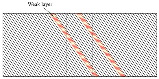
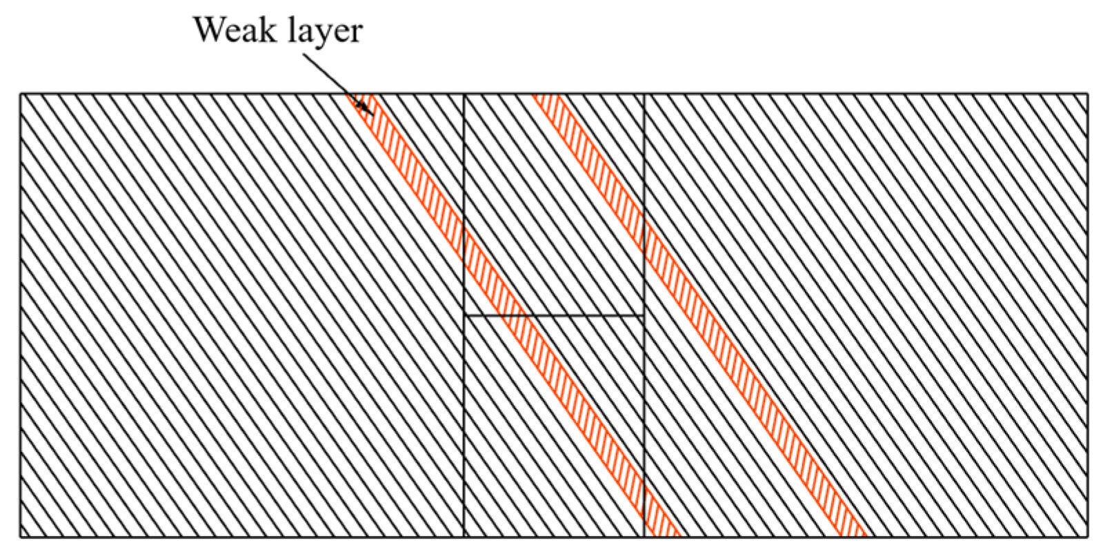
The position of the weak layer is shown in Figure 2. The deformation patterns identified in this study—including the bending–toppling deformation mode of anti-dip slopes and the step-shaped horizontal displacement distribution along the dip slope face—show good consistency with field observations and in situ monitoring data reported for high-dip layered rock foundation pits [24]. The deformation characteristics captured by field monitoring in this practical engineering case agree well with the numerical simulation results of the present study, providing solid empirical support for the reliability of the established numerical model.
Figure 2.
Schematic diagram of weak stratum location.
3.2. Influence of the Thickness of the Weak Stratum
To study the influence of the thickness of the weak layer, 5 factor levels are selected for research, and the calculation scheme is shown in Table 4.
Table 4.
The level of thickness factor in weak stratums.
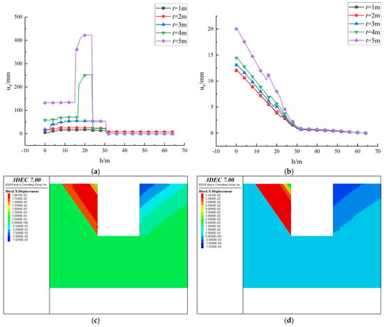
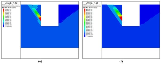
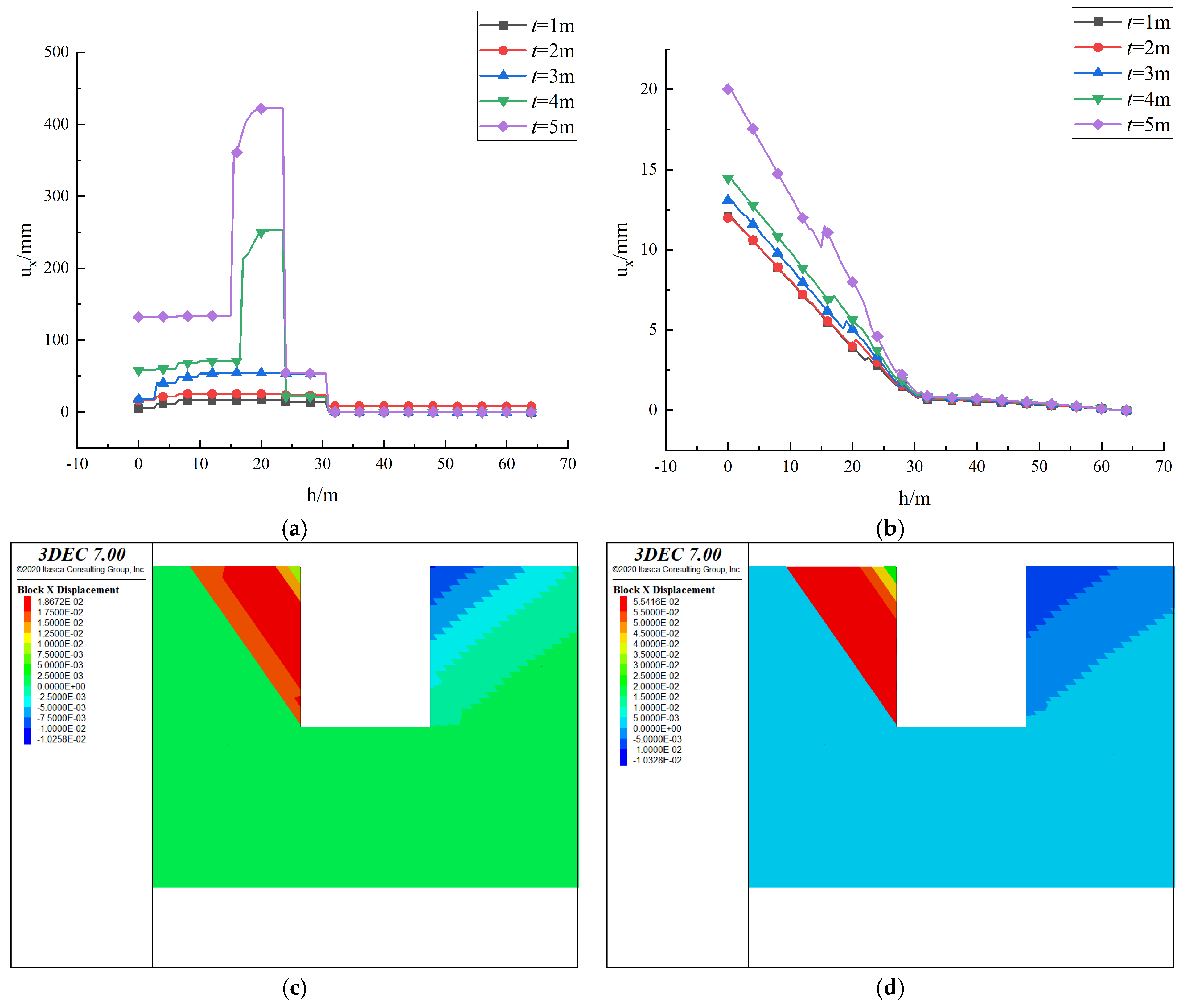
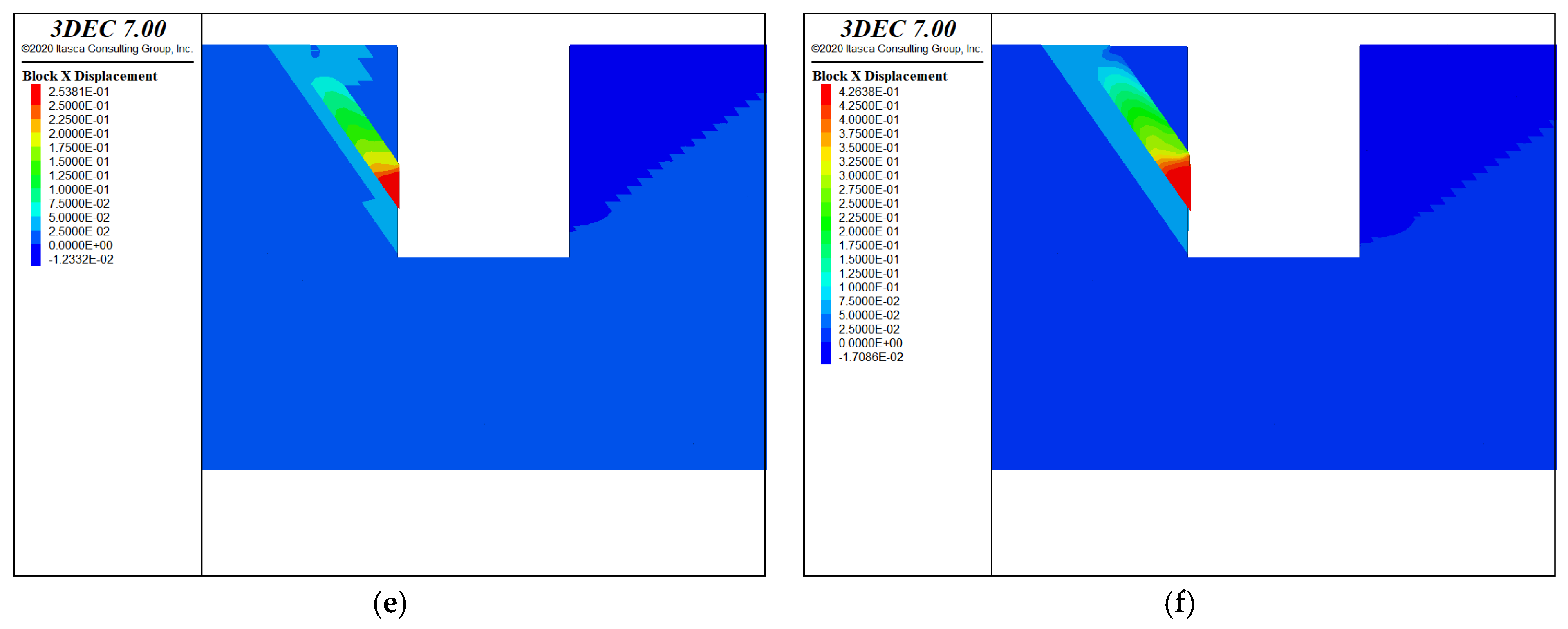
As shown in Figure 3a–f, the horizontal displacement curve along the depth at the slope surface of the dip side is step-shaped, the displacement of the rock stratum in the middle of the slope is relatively large, and the maximum displacement consistently occurs at the weak layer. The slope displacement generally increases with increasing thickness of the weak layer. When t = 5 m, the slope displacement is obviously large, and the displacement of the weak layer is obviously larger than that of the upper rock stratum; when t = 1~3 m, there is little difference between the displacement of the weak layer and the upper rock stratum.
Figure 3.
Horizontal displacement curves and contour clouds of dip slope and anti-dip slopes under different thicknesses of the weak stratums. (a) Horizontal displacement at the slope surface of the dip slope side. (b) Horizontal displacement at the slope surface of the anti-dip side. (c) t = 1 m. (d) t = 2 m. (e) t = 4 m. (f) t = 5 m.
This step-shaped horizontal displacement curve arises because the weak interlayer acts as a bedding-parallel shear zone; as its thickness increases, the zone of reduced shear resistance expands, allowing greater bedding-parallel slip. When t ≥ 4 m, the interlayer develops sufficiently thick extrusion deformation that its displacement clearly exceeds that of the adjacent hard rock, whereas for t ≤ 3 m, the clamping effect of the surrounding rock restricts interlayer expansion, resulting in displacement similar to the upper rock stratum.
The anti-dip slope produces bending and toppling deformation, and the horizontal displacement generally decreases with increasing depth, with the maximum displacement located at the top of the slope. The displacement at the weak layer is greater than that of the upper rock stratum, which is a local maximum. The slope displacement increases with increasing thickness of the weak layer. The displacement of the anti-dip slope is obviously smaller than that of the dip slope.
This bending-tensile toppling deformation is governed by the overturning moment generated by the self-weight of the cantilevered rock layers. The weak interlayer creates a local displacement peak due to its inherently lower elastic modulus compared to the intact rock mass, but because the anti-dip slope is subjected to compressive stress normal to bedding rather than bedding-parallel shear, the weak interlayer does not trigger a global sliding mechanism; instead, it merely modifies the local displacement field while the maximum displacement remains at the slope top.
The weak layer is squeezed by the upper rock stratum, resulting in deformation and extrusion towards the free face. The displacement gradually decreases from the slope surface to the interior of the slope, with the maximum displacement located at the slope surface. Due to the existence of the weak layer, the displacement of the upper rock stratum is relatively large, while that of the lower rock stratum is small. When t ≥ 4 m, the displacement of the weak layer is obviously larger than that of the hard rock; when t ≤ 3 m, there is little difference between the displacement of the weak layer and the upper rock stratum. When the anti-dip slope produces toppling deformation, the displacement increases at the weak layer, but the maximum displacement is located at the top. Compared with the dip side, the displacement of the anti-dip slope is smaller.
3.3. Influence of the Burial Depth of the Weak Stratums
To study the influence of the burial depth of the weak layer, five factor levels are selected for research, and the calculation scheme is shown in Table 5.
Table 5.
The level of factors affecting the burial depth of weak stratums.
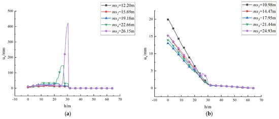
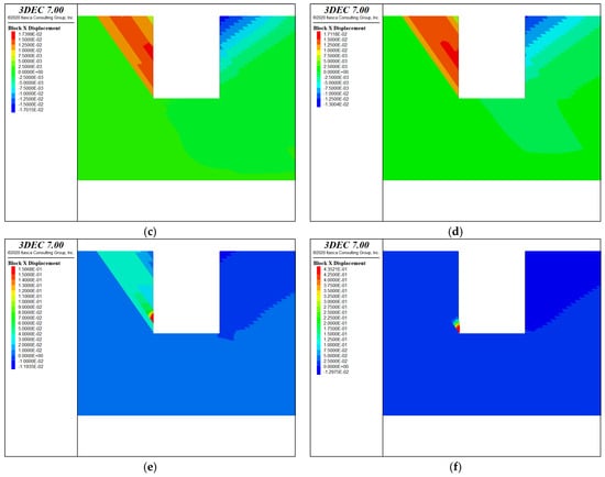
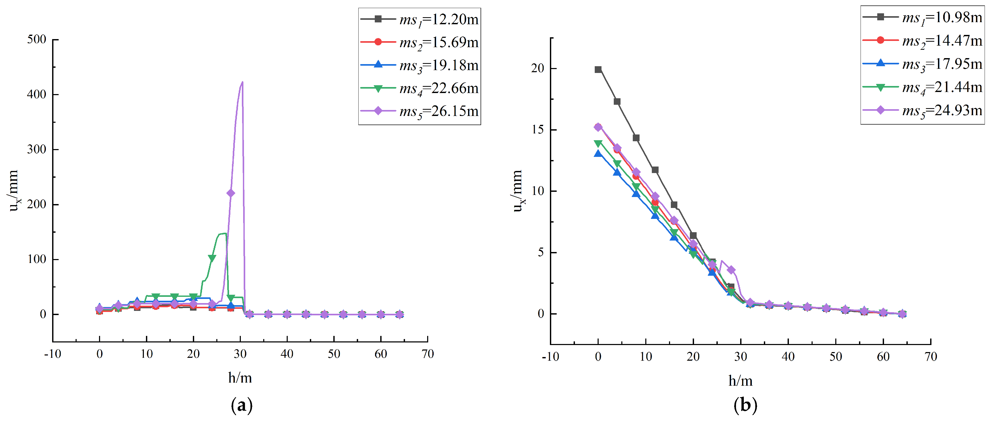
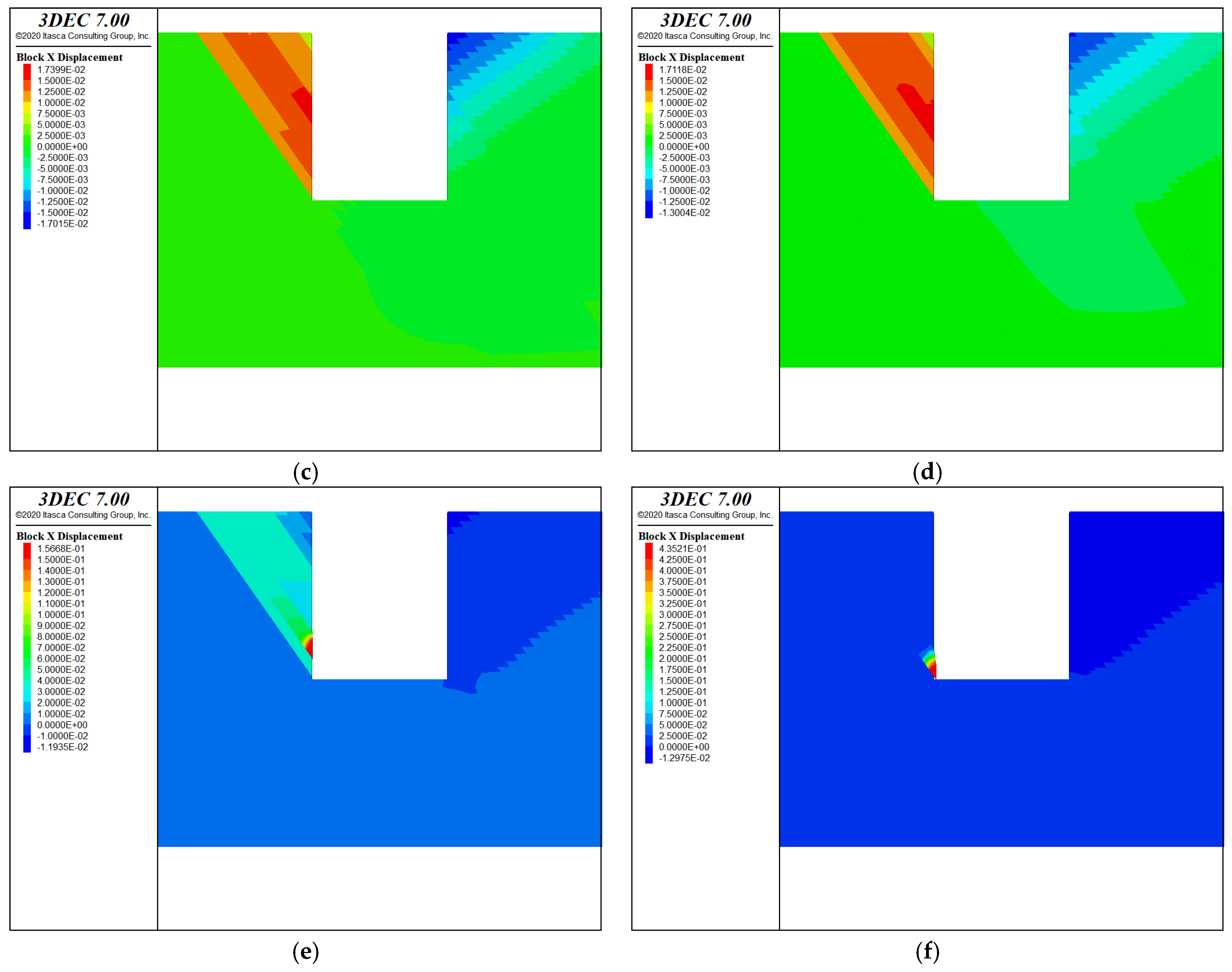
As shown in Figure 4a–f, the horizontal displacement curve along the depth at the slope surface of the dip side is step-shaped, the displacement of the rock stratum in the middle of the slope is relatively large, and the maximum displacement consistently occurs at the weak layer. The slope displacement generally increases with increasing burial depth of the weak layer. When ms = 22.66~26.15 m, the slope displacement is obviously large, and the displacement of the weak layer is obviously larger than that of the upper rock stratum; when ms = 12.20~19.18 m, there is little difference between the displacement of the weak layer and the upper rock stratum.
Figure 4.
Horizontal displacement curves and contour clouds of dip slope and anti-dip slopes under different burial depths of the weak stratums. (a) Horizontal displacement at the slope surface of the dip slope side. (b) Horizontal displacement at the slope surface of the anti-dip side. (c) ms = 10.98 m. (d) ms = 14.47 m. (e) ms = 21.44 m. (f) ms = 24.93 m.
For the dip slope side, deeper interlayers are located further from the slope surface in a region of higher confining stress, yet the increased gravitational loading on the overlying rock mass produces greater driving shear force along the interlayer, leading to larger displacement. This mechanical explanation clarifies why slope displacement rises sharply when interlayer burial depth reaches 22.66–26.15 m.
The anti-dip slope produces bending and toppling deformation, and the horizontal displacement generally decreases with increasing depth, with the maximum displacement located at the top of the slope. The displacement at the weak layer is greater than that of the upper rock stratum, which is a local maximum. The slope displacement first decreases and then increases with increasing burial depth of the weak layer, among which the horizontal displacement of the slope is the largest when ms = 10.98 m. The displacement of the anti-dip slope is obviously smaller than that of the dip slope.
For the anti-dip side, the burial depth effect is non-monotonic because the interlayer position relative to the bending moment distribution along the cantilevered slope governs the local displacement peak. When the interlayer is located near the slope top (shallow burial), the cantilevered rock column above it is shorter, resulting in a smaller overturning moment; as burial depth increases, the column length increases and the bending moment intensifies, but excessively deep interlayers are constrained by higher confining stress at depth, leading to a decrease-then-increase trend in displacement.
The weak layer is squeezed by the upper rock stratum, resulting in deformation and extrusion towards the free face. The displacement gradually decreases from the slope surface to the interior of the slope, with the maximum displacement located at the slope surface. After one-time excavation, the rock stratum above the structural plane slides down as a whole. Due to the existence of the weak layer, the displacement of the upper rock stratum is relatively large, while that of the lower rock stratum is small. When ms ≥ 22.66 m, the displacement of the weak layer is obviously larger than that of the hard rock; when ms ≤ 19.18 m, there is little difference between the displacement of the weak layer and the upper rock stratum. When the anti-dip slope produces toppling deformation, the displacement increases at the weak layer, but the maximum displacement occurs at the top.
4. Discussion
(1) Asymmetric deformation response of dip slope and anti-dip slopes
Weak interlayers produce completely different effects on the two slope types due to stress path differences. Dip slope sides bear bedding-parallel shear stress from overlying rock, so interlayer thickness and burial depth directly control horizontal displacement, with large deformation concentrated in the middle-lower section of the interlayer. Anti-dip sides are dominated by bending-tensile toppling failure, and interlayers only cause local displacement peaks without changing the global deformation trend; obvious interlayer extrusion only occurs at extremely low cohesion of = 0.0122 MPa.
(2) Quantitative critical thresholds for interlayer-controlled deformation
Two engineering-applicable critical values are identified in this study: thickness threshold, when interlayer thickness t ≥ 4 m, interlayer extrusion displacement is distinctly larger than adjacent hard rock, and t ≤ 3 m shows no obvious displacement difference between soft and hard strata due to the clamping effect of surrounding rock, and bis depth threshold, when slope displacement rises sharply when interlayer burial depth reaches 22.66–26.15 m, with interlayer displacement far exceeding overlying rock, while shallow-buried interlayers (12.20–19.18 m) only cause limited deformation. All large deformation zones are distributed along the strike of weak interlayers.
(3) Engineering implications and brief limitations
The results provide direct guidance for support design of karst rock foundation pits: dip slope sides should focus on reinforcement of thick, deep-buried interlayers in the middle-lower slope to prevent interlayer extrusion, while anti-dip sides should prioritize slope top anti-toppling protection without excessive reinforcement of shallow weak interlayers. This study only considers single weak interlayer conditions under static excavation, and the proposed critical thresholds can be further verified through field monitoring in subsequent work. Specifically, when the weak interlayer thickness t ≥ 4 m and burial depth ms ≥ 22.66 m, the interlayer extrusion becomes the dominant failure mechanism on the dip slope side. In such cases, support design should prioritize interlayer reinforcement (e.g., grouting or anchor installation within the interlayer) rather than general slope surface protection. For the anti-dip side, the weak interlayer has negligible influence on global stability unless cohesion falls below 0.0122 MPa; support design should, therefore, focus on slope-top anti-toppling measures (e.g., retaining walls at the crest), with limited need for deep interlayer reinforcement.
5. Conclusions
(1) The thickness and burial depth of the weak interlayer exert prominent effects on the horizontal displacement of the dip slope side. Relatively large displacement values appear at the middle and lower segments of the weak interlayer on the dip slope side. Owing to the weak interlayer, the upper hard rock stratum of the slope generates larger displacement than the lower hard rock stratum. By contrast, the weak interlayer imposes negligible impacts on the horizontal displacement of the anti-dip side; it only alters the displacement tendency by forming a local displacement maximum within the weak interlayer. Obvious excessive displacement of the weak interlayer can only be observed when the cohesion is 0.0122 MPa.
(2) Squeezed by the overlying rock mass, the weak interlayer deforms and extrudes toward the excavation free face. The displacement gradually decreases inward from the slope surface, where the maximum displacement occurs. The weak interlayer contributes to larger displacement of the overlying rock mass and smaller displacement of the underlying rock mass. When the interlayer thickness t ≥ 4 m, the displacement of the weak interlayer is distinctly larger than that of hard rock; when t ≤ 3 m, the displacement difference between the weak interlayer and upper rock mass is insignificant. The anti-dip side develops toppling deformation with slight displacement growth within the weak interlayer, yet its maximum displacement emerges at the slope top. Overall, the displacement magnitude of the anti-dip side is lower than that of the dip slope side.
(3) Regions with large displacement are all distributed along the weak interlayer. Generally, slope displacement rises with increasing burial depth of the weak interlayer. When the burial depth ms = 22.66~26.15, the slope displacement increases sharply, and the weak interlayer displacement far exceeds that of the overlying rock mass; when ms = 12.20~19.18, the displacement discrepancy between the weak interlayer and upper rock mass is limited.
Author Contributions
Conceptualization, C.L.; writing—original draft preparation, J.X.; visualization, B.Z.; formal analysis, X.W.; investigation, data curation, Y.W. All authors have read and agreed to the published version of the manuscript.
Funding
This work was supported by the National Natural Science Foundation of China (Grant No. 52074264), the Nantong Natural Science Foundation of China (Grant No. JC2023055, JC2023056), and the Basic Science Fund of Institutions of Higher Education in Jiangsu Province (Grant No. 25KJB560018).
Institutional Review Board Statement
Not applicable.
Data Availability Statement
The original contributions presented in this study are included in the articles. Further inquiries can be directed to the corresponding author.
Acknowledgments
The authors would like to express sincere gratitude to all colleagues for their valuable suggestions and assistance during the research and manuscript preparation. We also thank the relevant engineering units for providing field engineering data and giving great support to this work.
Conflicts of Interest
The authors declare no conflicts of interest.
References
- Zhang, S.; Shi, W.; Yang, C.; Wang, Y.; Yu, X. Experimental evaluation of gentle anti-dip slope deformation and fracture network under the action of underground mining. Landslides 2022, 20, 381–408. [Google Scholar] [CrossRef] [Scilit]
- Lin, Q.; Cheng, Q.; Li, K.; Xie, Y.; Wang, Y. Contributions of rock mass structure to the emplacement of fragmenting rockfalls and rockslides: Insights from laboratory experiments. J. Geophys. Res. Solid Earth 2020, 125, e2019JB019296. [Google Scholar] [CrossRef] [Scilit]
- Chen, B.L.; Yang, W.J.; Xie, Q.; Peng, H.Y.; Ye, X.M.; Tan, K.; Zhou, P. Calculation of active rock pressure for slope sliding along weak outward inclined structural plane. Rock Soil Mech. 2023, 44, 3272–3279. [Google Scholar] [CrossRef]
- Yi, W.; Zhao, H.Q.; Huang, H.F.; Deng, Y.H.; Yan, G.Q. Failure mechanism of the rock slope at Xiulong, the Three Gorges area. Chin. J. Geol. Hazard. Control 2016, 27, 13–17. [Google Scholar] [CrossRef]
- An, H.; Li, G.; Liu, H.; Konietzky, H.; Han, H. Analyzing toppling failure in anti-dip rock slopes using GPGPU-parallelized hybrid finite-discrete element method. Bull. Eng. Geol. Environ. 2026, 85, 267. [Google Scholar] [CrossRef] [Scilit]
- Wang, Z.; Qi, C.; Zhang, Z.; Huang, R.; Guo, C.; Dong, L.; Zheng, R. Improved in-situ direct shear test of rock mass structural plane and its application to stability analysis of bedding slope. Case Stud. Constr. Mater. 2025, 23, e04976. [Google Scholar] [CrossRef] [Scilit]
- Chan, P.C.; Lin, M.L.; Chang, K.J. Characteristics and scale effect of joint roughness coefficient on failure planes of consequent bedding-parallel rock slopes. J. Chin. Inst. Civ. Hydraul. Eng. 2016, 28, 129–137. [Google Scholar] [CrossRef]
- Chen, G.; Zhang, Y.; Xu, Q.; Zhu, Z.; Zheng, X.; Wang, J.; Zou, M. Experimental investigation on the influence of dip angle and layer thickness of overlying rock layers on the failure process of bedding slopes. Rock Mech. Rock Eng. 2025, 58, 8195–8220. [Google Scholar] [CrossRef] [Scilit]
- Wang, B.; Zhao, Q.H.; Liang, G.C.; Wan, Z.J.; Qin, L.; Lu, L. Mechanism of deformation and failure of inclined layered slopes based on discrete element method simulations. Soil Mech. Found. Eng. 2025, 62, 127–133. [Google Scholar] [CrossRef] [Scilit]
- Zhang, J.; Huang, D.; Li, Z.; Guo, Z.; Song, Y.; Xiao, H. Step-path failure of the rock slopes with large intersection angles between the strikes of strata and surface: A case study. J. Mt. Sci. 2025, 22, 931–949. [Google Scholar] [CrossRef] [Scilit]
- Zhang, Z.; Li, W.; Hu, A.; Wu, L. Physical test and numerical analysis of damage mechanism of rocky foundation with parallel structural surfaces. Buildings 2025, 15, 371. [Google Scholar] [CrossRef] [Scilit]
- Li, R.J.; Hu, F.H.; Shi, Y.C.; Wang, L.; Lv, K.W. A study of deformation process and failure mechanism of hard rock slope based on the bottom friction test. Hydrogeol. Eng. Geol. 2022, 49, 145–152. [Google Scholar] [CrossRef]
- Hou, W.L. Research on Large-Scale Shaking Table Physical Simulation Experiment of Steep-Dipping Stratified Rock Slope. Master’s Thesis, Chengdu University of Technology, Chengdu, China, 2011. [Google Scholar]
- Lin, H.; Cao, P.; Li, J.T.; Jiang, X.L.; He, Z.M. Numerical analysis of failure modes and stability of stratified rock slopes. Rock Soil Mech. 2010, 31, 3300–3304. [Google Scholar] [CrossRef]
- Zhang, X.D. Study on Deformation and Failure Mechanism of Typical Metamorphic Rock Slope in Wenchuan-Maerkang Expressway. Master’s Thesis, Chang’an University, Xi’an, China, 2017. [Google Scholar]
- Qiu, J.; Ren, G.M.; Wang, Y.N. Characteristics of forming conditions and development scale of toppling in anti-dip and dip stratified slopes. Rock Soil Mech. 2016, 37, 513–524. [Google Scholar] [CrossRef]
- Yang, G.; Qi, S.; Fan, Y.; Li, L.; Peng, J. Deep-seated zonal damage in anti-dip layered rock slope: A case study in Southwest China. J. Rock Mech. Geotech. Eng. 2025, 18, 4402–4415. [Google Scholar] [CrossRef] [Scilit]
- Li, X.; Wang, Y.; Liu, Z.; Zhao, K. Catastrophic mechanism analysis of deformation and instability of the layered rock slope. IOP Conf. Ser. Earth Environ. Sci. 2021, 634, 012031. [Google Scholar] [CrossRef] [Scilit]
- Ding, C.; Xue, K.; Zhou, C. Case study on long-term deformation monitoring and numerical simulation of layered rock slopes on both sides of wudongde dam reservoir area. Sci. Rep. 2024, 14, 6742. [Google Scholar] [CrossRef] [Scilit] [PubMed]
- Wang, C.; Jin, L.; Fu, W.; Ye, F.; Qian, R.; Lv, G.; Yao, S. Failure mechanism of toppling in anti-dip layered rock slope: A case study of the xiangpingshan landslide in Southwest China. Bull. Eng. Geol. Environ. 2024, 84, 12. [Google Scholar] [CrossRef] [Scilit]
- Zhang, Z.; Li, W.; Luo, R.; Peng, C.; You, X.; Wang, C.; Wang, D. Study on the damage mechanism of excavation in rocky foundation pit within steeply dipping structural plane. Discov. Appl. Sci. 2024, 7, 18. [Google Scholar] [CrossRef] [Scilit]
- GB/T 50218-2014; Standard for Engineering Classification of Rock Mass. China Planning Press: Beijing, China, 2014.
- Yuan, R. Study on the Stability of Foundation Pit for Metro Station Excavated in Steep Strata. Master’s Thesis, China University of Mining and Technology, Xuzhou, China, 2021. [Google Scholar] [CrossRef]
- Xu, J. Sliding Failure Law and Supporting Technology for Cave-Developed Bedding Rock Slopes in Deep Foundation Pits. Ph.D Thesis, China University of Mining and Technology, Xuzhou, China, 2022. [Google Scholar] [CrossRef]

Disclaimer/Publisher’s Note: The statements, opinions and data contained in all publications are solely those of the individual author(s) and contributor(s) and not of MDPI and/or the editor(s). MDPI and/or the editor(s) disclaim responsibility for any injury to people or property resulting from any ideas, methods, instructions or products referred to in the content. |
© 2026 by the authors. Licensee MDPI, Basel, Switzerland. This article is an open access article distributed under the terms and conditions of the Creative Commons Attribution (CC BY) license.