


Abstract
Residual plastic film recovered from arid farmland in Northwest China cannot be processed by water-washing melt granulation, because dry cleaning leaves too much soil and straw in the film. This study optimizes a self-developed dry granulation device that converts such film into particles by friction-induced heating. First, the feeding, cutting and stirring processes were analyzed to identify the moving-cutter rotational speed, the fixed-cutter edge angle and the stirring-blade upper-end length as the key structural parameters. Second, Fluent, LS-DYNA and EDEM simulations were used to determine their reasonable ranges. Third, single-factor and Box–Behnken tests were carried out with the residual-film utilization rate (Y1) and granulation rate (Y2) as responses, and regression models were fitted (R2 = 0.984 and 0.989). The optimal combination was 665.86 r/min, 45.58° and 97.24 mm, for which the models predicted Y1 = 92.77% and Y2 = 95.58%. Field verification gave 91.71% and 94.08%, with relative errors of 1.14% and 1.57%. The results provide a basis for the design and parameter selection of dry granulation equipment for residual film.
1. Introduction
Plastic-film mulching is one of the most effective practices for increasing crop yields in the arid and semi-arid regions of Northwest China, because it conserves soil moisture, raises soil temperature and suppresses weeds [1,2]. Its widespread adoption has also made waste mulch film a major source of agricultural pollution. Annual film consumption in China now exceeds 2 million tonnes, about 75% of the global total [3], and although mechanized recovery rates exceed 85% in many regions [4,5], a large part of the recovered film is stockpiled, landfilled or dumped. Wind and water then redistribute it, causing transboundary pollution [6,7], reducing soil bulk density, porosity and air permeability [8], and contaminating straw-based livestock feed [9]. Converting the recovered film into a transportable product is therefore essential for closing the recycling loop.
Water-washing melt granulation is currently the dominant conversion technology, but it requires a feedstock whose impurity content is below about 0.2%, so the film must be washed before granulation; the process consumes large amounts of water and generates wastewater. Dry impurity-removal devices—drum screens, disk screens and air separators—have therefore been developed to replace washing [4,5,10]. Their strengths and limitations differ in practice: drum screens are robust and high-throughput but tend to wrap film around the drum and to be blocked by stalks; disk screens separate soil effectively but are sensitive to wet, sticky film; air separators are efficient for light film but their performance depends strongly on the moisture content and on the stability of the airflow field [10]. None of them removes fine soil and dust completely, so the film leaving dry cleaning still contains far more impurities than water-washing granulation can tolerate. This mismatch—efficient dry cleaning on one side and a washing-based granulation process on the other—is the practical problem addressed in this study.
To bridge this gap, dry granulation devices have been developed that convert cleaned film directly into particles by friction-induced heating; our group built such a device and reported its structural design and preliminary tests in [11]. In that device, the film is fed into a cylinder, cut between moving and fixed cutters and stirred by blades until it agglomerates, but the design relied mainly on experience and the quantitative links between the structural parameters and the performance were not established. Numerical simulation offers a route to such an analysis. Computational fluid dynamics has been used for airflow and ventilation problems [12], explicit finite-element analysis for cutting and soil–tool interaction [13,14,15], the discrete element method for particle and soil motion [16,17], and response surface methodology (RSM), often combined with simulation and physical tests, for multi-parameter optimization [18,19,20,21]. These tools also have limits: CFD needs careful treatment of turbulence and of the rotating zone, explicit analyses need a fracture criterion, DEM predictions depend on the contact parameters, and RSM models are local approximations that require experimental validation.
Nevertheless, no study has systematically linked the mechanism of dry granulation to its structural parameters. The work on dry cleaning stops at the cleaning stage, and [11] reports the design and overall performance of the device without explaining how the film is fed, cut and stirred or how the structural parameters affect the performance indices. Consequently, the feeding and granulation performance of existing devices is still tuned by trial and error, which is the problem observed in the field, namely poor feeding performance and unsatisfactory granulation.
Against this background, this study addresses four questions: (1) which forces govern the feeding, cutting and stirring of the film, and which structural parameters control them; (2) how can the airflow field, the cutting deformation and the particle motion be reproduced numerically so that the parameter ranges can be narrowed; (3) how do the moving-cutter speed, the fixed-cutter edge angle and the upper-end length of the stirring blade affect the residual-film utilization rate and granulation rate; and (4) which combination of these parameters gives the best overall performance? The work follows four steps: theoretical force analysis of the three processes; simulation with Fluent 2024 R1, LS-DYNA 2024.2 and EDEM 2024.1; single-factor and Box–Behnken tests analyzed by RSM; and prototype verification in the field. Its main contributions are (i) a force model that relates the cutting resistance to the cutter edge angle and the film thickness; (ii) a simulation-based procedure for determining the parameter ranges; (iii) regression models that link the three structural parameters to the utilization and granulation rates, together with an optimum of 665.86 r/min, 45.58° and 97.24 mm; and (iv) field verification giving 91.71% utilization and 94.08% granulation. Compared with our earlier work [11], which dealt with the structural design of the device, this study reveals the working mechanism, establishes quantitative parameter–performance relationships and provides a validated optimization procedure; no experimental data from [11] are reused except the material and contact parameters listed in Table 1.
Table 1.
Parameter settings.
2. Materials and Methods
2.1. Overall Structure and Working Principle
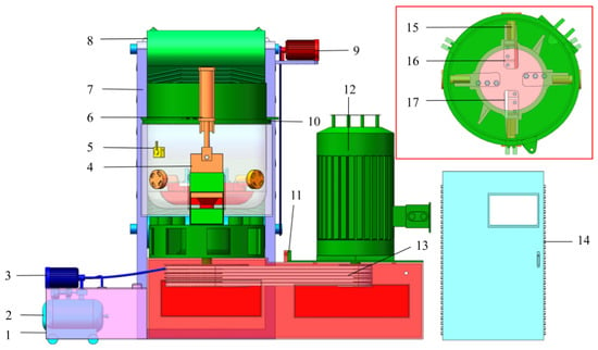
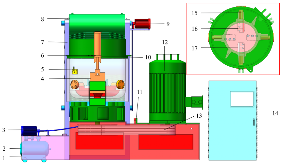
The residual plastic film dry granulation device, developed by our group and first reported in [11], mainly consists of a granulation cylinder (10), moving cutters (16), fixed cutters (15), a discharge plate (4), a drive motor, a feeding system, a pneumatic system, an oil supply system, and a control system, as shown in Figure 1. The moving cutters are composed of film-pushing blades, film-cutting blades, a moving cutter base, and stirring blades (17), whose function is to cut the residual films and push them to rub against the cylinder wall. The feeding system mainly comprises a feeding motor, a conveyor belt, and a feeding device frame, which serves to transport residual films into the granulation cylinder. The pneumatic system mainly consists of an air pump, air delivery plastic hoses, pneumatic solenoid valves, and pneumatic pistons, enabling the discharge plate to perform specified actions. The oil supply system mainly includes a lubricating oil tank, a lubricating oil pump, and oil delivery plastic hoses, which deliver lubricating oil to the moving cutter shaft to reduce component wear and improve heat dissipation efficiency. The control system mainly consists of a control cabinet, a PLC controller, a touch screen, and temperature sensors, whose main function is to monitor the ambient temperature and control the device operation in combination with operating parameters.
Figure 1.
Overall structure of the residual plastic film dry granulation device. 1. Lubricating oil tank; 2. Air pump; 3. Lubricating oil pump; 4. Discharge plate; 5. Pneumatic solenoid valve; 6. Pneumatic piston; 7. Feeding device frame; 8. Conveyor belt; 9. Feeding motor; 10. Granulation cylinder; 11. Device base; 12. Drive motor; 13. Drive belt; 14. Power distribution cabinet; 15. Fixed cutter; 16. Moving cutter; 17. Stirring blade.
After the device is powered on, the start button on the touch screen is pressed, and the lubricating oil pump starts to operate. Meanwhile, the drive motor drives the moving cutter to rotate via belt drive, and the feeding motor drives the conveyor belt to run via chain drive. The residual plastic films are transported by the conveyor belt from the previous-stage impurity removal device into the granulation cylinder. Inside the cylinder, the residual films are first cut into small film fragments by the film-cutting blades of the moving cutter and the fixed cutters. Under the downward pressure exerted by the incoming residual films, these small film fragments move toward the bottom of the cylinder. The film-pushing blades agitate the residual films at the cylinder bottom to rub against the cylinder wall. With the accumulation of frictional heat, the temperature rises, and the residual films gradually granulate. The temperature sensors transmit real-time temperature change information to the PLC controller. When the preset discharge temperature is reached, the PLC controller stops the conveyor belt. Under the control of the PLC controller, the pneumatic piston pulls the discharge plate upward, and the residual film particles gradually flow out from the discharge port under the rotational agitation of the moving cutter. After the cylinder cools down, the discharge plate resets to its original position, the conveyor belt restarts, and the device begins a new round of granulation operation.
2.2. Operational Process Analysis
2.2.1. Analysis of Residual Plastic Film Feeding Process
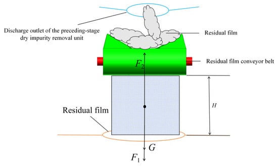
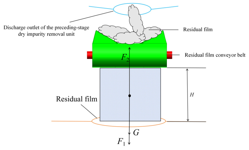
The residual plastic films fall from the discharge port of the impurity removal device onto the horizontal conveyor belt below. The other end of the conveyor belt is located directly above the cylinder feeding port to ensure that the residual films accurately fall into the granulation cylinder. The moving cutter is in a state of high-speed rotation, causing the air inside the cylinder to be discharged at a high speed (outflow air), while the external air enters the cylinder through the feeding port (inflow air). When the outflow air impacts the residual films, the residual films are subjected to an upward pressure difference resistance. Under the action of the pressure difference resistance, the residual films move upward and overlap with the subsequently fed residual films. Meanwhile, the residual films are also subjected to the downward pushing effect of the inflow air. As the subsequent residual films are continuously fed, the gravity acting on the overlapping residual film mixture gradually increases until it exceeds the pressure difference resistance, and the residual film mixture starts to move downward. When the residual film mixture reaches the feeding port, it can be regarded as a cylinder. The forces acting on it are shown in Figure 2.
Figure 2.
Residual film feeding force analysis. Note: F1 is the inlet airflow thrust force, N; F2 is the outlet airflow pressure difference resistance, N; H is the distance between the upper side conveyor belt of the conveying device and the cylinder end cover, mm.
During the feeding process, the forces acting on the residual films are analyzed under ideal conditions, neglecting the viscosity of the airflow and the angular velocity generated by the rotation of the residual films themselves. The critical condition for residual film feeding is that the sum of the gravity of the residual film mixture and the thrust force of the inflow air equals the pressure difference resistance formed by the outflow air. At this point, the residual film mixture is in force equilibrium and maintains uniform motion. The expression for the critical condition of the residual film mixture feeding into the cylinder is as follows:
In the formula, Fin represents the pushing force of the inflow air on the residual film mixture (N); Fout denotes the pressure difference resistance of the outflow air on the mixture (N); A is the bottom area of the residual film mixture (m2); CD is the drag coefficient; ρ is the air density under normal temperature and pressure (kg/m3); ρc is the residual film density (kg/m3); vin is the average velocity of the inflow air at the feeding port (m/s); vout is the average velocity of the outflow air at the feeding port (m/s); G is the weight of the residual film mixture (N); H is the distance between the upper conveyor belt of the conveyor device and the barrel end cover (m). In addition, F1 and F2 in Equation (1) denote the inlet thrust force and the outlet pressure-difference resistance defined in Figure 2, i.e., F1 = Fin and F2 = Fout, and v1 and v2 in Equation (2) denote vin and vout, respectively.
Equation (1) is simplified to obtain the expression for the outflow air velocity v2 as follows:
2.2.2. Analysis of Residual Plastic Film Cutting Process
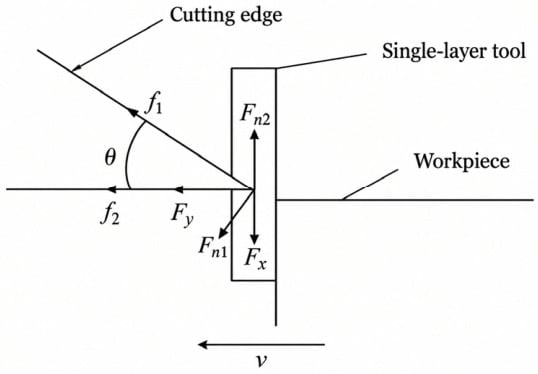
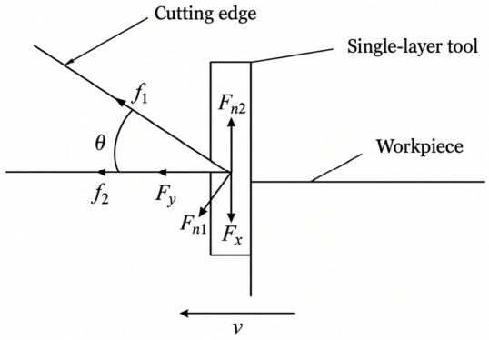
The residual plastic film cutting process is a relatively complex process. Due to the differences in the morphology and lamination thickness of film fragments, analyzing each residual film cutting process individually would involve a large workload. To simplify the analysis process, the residual films being cut are regarded as composed of several residual film unit bodies. During the cutting process, the fixed cutters remain stationary, and a large number of film fragments gradually approach the fixed cutters under the rotation of the film-cutting blades. To facilitate kinematic analysis, a new kinematic reference frame is established, and the residual film unit body is taken as the stationary reference object. In this frame, the fixed cutter cuts the residual film unit body at the same speed in the opposite direction. The cutting of residual films by the fixed cutter can be divided into two stages: compression and cutting. Specifically, the cutting process of a residual film unit body by the fixed cutter mainly includes two stages: (1) The force generated during the process where the blade compresses the residual film unit body and causes it to undergo plastic deformation; (2) The effective cutting force required by the fixed cutter to perform cutting after the residual film unit body has deformed. This paper focuses on analyzing the forces acting on the residual film unit body during cutting by the fixed cutter, as shown in Figure 3.
Figure 3.
Schematic diagram of forces acting on residual plastic film during cutting. θ—fixed cutter edge angle, °; f1—friction force on the inclined surface of the fixed cutter, N; f2—friction force on the horizontal surface of the fixed cutter, N; Fn1—elastic restoring force of the residual film unit body perpendicular to the inclined surface of the fixed cutter, N; Fn2—elastic restoring force of the residual film unit body in the vertical direction, N; Fx—horizontal component force of Fn1, N; Fy—vertical component force of Fn1, N; v—moving speed of the fixed cutter in the new coordinate system, m/s.
In the initial compression stage, the force exerted by the residual film unit body on the fixed cutter edge is the elastic force FN generated by the compression of the residual film unit body. According to Hooke’s law, FN is expressed as:
FN—elastic force of residual plastic film, N; k0—elastic recovery modulus of residual plastic film, N/m; l1—compressed length of the residual film unit body, m.
From Equation (3), it can be seen that as the degree of compression exerted by the fixed cutter on the residual film unit body increases, the elastic force of the residual film unit body gradually increases.
During the cutting process, the fixed cutter is subjected to various normal forces. Among them, the normal force Fn1 can be decomposed into a horizontal component force Fx and a vertical component force Fy, and the relational expressions are as follows:
Under the action of the elastic restoring force, the fixed cutter is subjected to friction forces f1 and f2, and their respective calculation formulas are as follows:
μ—coefficient of friction between the fixed cutter and the residual plastic film.
During the cutting process of the residual film unit body by the fixed cutter, the cutting resistance acting in the horizontal direction is the sum of the friction force on the horizontal surface, the horizontal component of the friction force on the inclined surface, and the horizontal component of the normal force on the inclined surface, and its calculation formula is expressed as:
Substituting Equations (5) and (6) into Equation (7) yields:
Ff—cutting resistance, N.
During the cutting-off of the residual film unit body by the fixed cutter, the normal force Fn2 remains unchanged because the horizontal cutting surface of the fixed cutter is parallel to the movement direction. The normal force Fn1 acting on the inclined face of the fixed cutter increases continuously, which leads to a gradual rise in the friction force f1 on this cutter face. According to Hooke’s law, the compression deformation thickness of the residual film unit body is denoted as hx in the cutting process, and the normal force Fn1 can be expressed as:
l2—thickness of the residual film unit body, m. k—equivalent elastic modulus of the residual film per unit contact area, N/m2 (k = k0/Ac, where Ac is the contact area of the residual film unit body).
Substituting Equation (9) into Equation (8) and simplifying gives:
According to Equation (10), when the friction coefficient μ between the fixed cutter and residual plastic film, the elastic recovery modulus k of residual film and the thickness l2 of the residual film unit body remain constant, the cutting resistance is mainly controlled by the edge angle of the fixed cutter. The cutting resistance rises gradually with the increase in edge angle θ. Nevertheless, an excessively small edge angle will reduce cutter strength and wear resistance. Referring to the relevant literature [14], the edge angle of cutting tools widely adopted in agricultural machinery ranges from 30° to 60°. Accordingly, the preliminary selection range for the fixed cutter edge angle is set as 30~60°.
2.2.3. Analysis of Residual Plastic Film Stirring Granulation Process
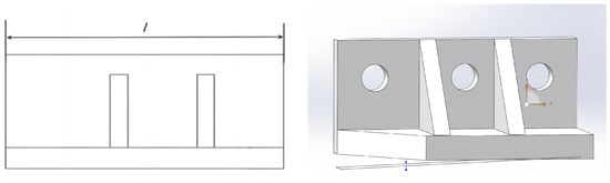
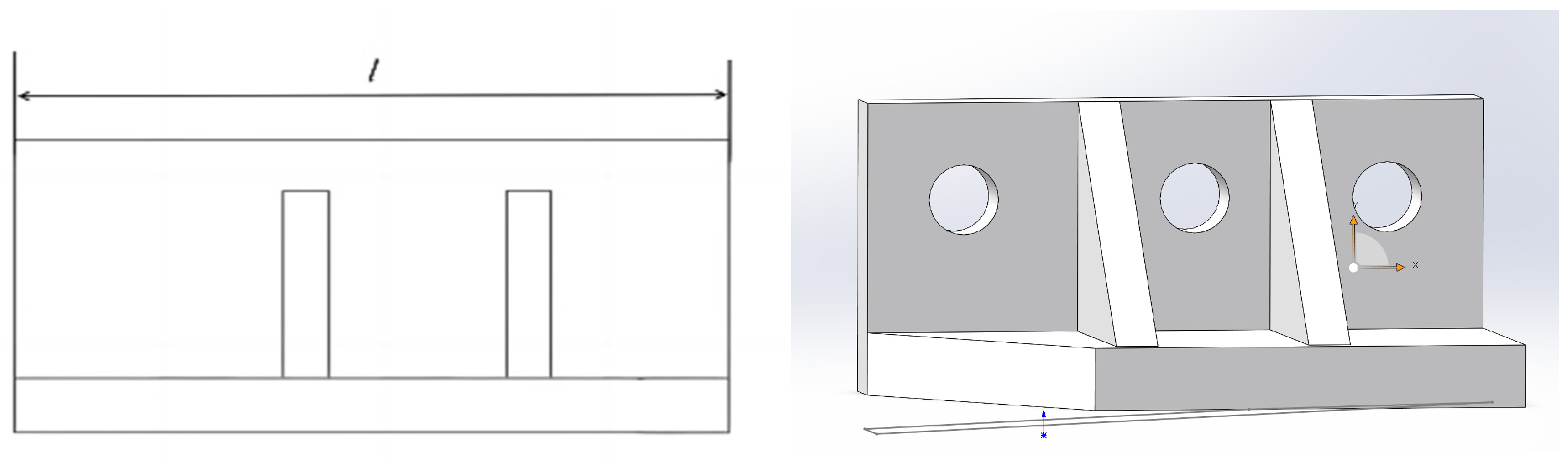
As residual plastic films are continuously granulated into particles, a large number of residual film particles accumulate at the bottom of the cylinder. The film-pushing blades at the cylinder bottom continuously agitate the particles, inducing friction between the particles and the cylinder wall. The continuously accumulated heat causes the residual film particles to soften, adhere and agglomerate. To address this issue, stirring blades are arranged to turn over the residual film particles. The stirring blade is fabricated by perpendicularly welding two stainless steel plates, with two reinforcing ribs installed in the middle to enhance its structural stability, as shown in Figure 4.
Figure 4.
Structural schematic diagram of the mixing blade. Notes: l—upper end length of the stirring blade, mm.
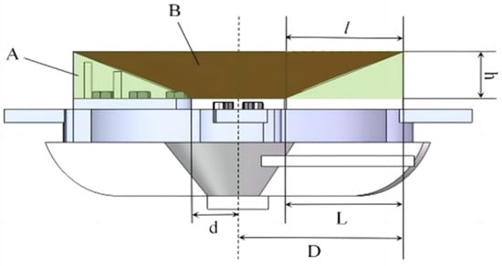
Feng Zhongxu et al. found through research that the volume of material pushed by the stirring blade per revolution is closely related to stirring performance, and the two exhibit a proportional relationship. In this paper, the volume of material pushed by the stirring blade per revolution is adopted as the working performance index of the stirring blade. Neglecting the thickness of the stirring blade, the volume of material pushed by the stirring blade per revolution can be approximated as the difference between the volume of a cylinder (Region A) and the volume of a circular frustum (Region B) with the same base, as shown in Figure 5. When the upper end length of the stirring blade is l and the lower end length is L, the calculation formula for the geometric volume is expressed as:
Vl—volume of material, m3; D—radius of the rotation path of the distal end of the stirring blade, i.e., the distance from the rotation axis, m; d—radius of the rotation path of the proximal end, i.e., the distance from the rotation axis, m; h—height of the stirring blade, m; l—upper end length of the stirring blade, m; L—lower end length of the stirring blade, m.
Figure 5.
Schematic diagram of mixed material volume. Notes: Green region A is the rotation area of the stirring blade; Brown region B is the cavity formed when the stirring blade agitates residual plastic film particles; the value range of l is 0–150 mm; the drawing illustrates the case l = L = 150 mm.
According to the design requirements, the lower end length of the stirring blade is L = 0.15 m, the diameter of the maximum rotation range of the stirring blade is 0.45 m (hence D = 0.225 m), the distance between the proximal end of the stirring blade and the rotation axis is d = 0.075 m, and the height of the stirring blade is h = 0.085 m. Substituting these data into Equation (11) yields:
From Equation (12), it can be seen that the greater the upper end length of the stirring blade, the better the stirring performance for residual plastic film particles. However, as the upper end length of the stirring blade increases, its acceleration effect on the outlet airflow becomes stronger, which leads to higher resistance acting on the residual film during the feeding process. Based on the above analysis, the optimal value range of the upper end length of the stirring blade is determined as 75–125 mm.
2.3. Simulation Analysis of Working Process
The three simulations are independent: Fluent resolves the airflow field at the feeding port, LS-DYNA the cutting of the equivalent film, and EDEM the motion of the particles; no data are transferred between the three codes.
2.3.1. Simulation Analysis of Feeding Process
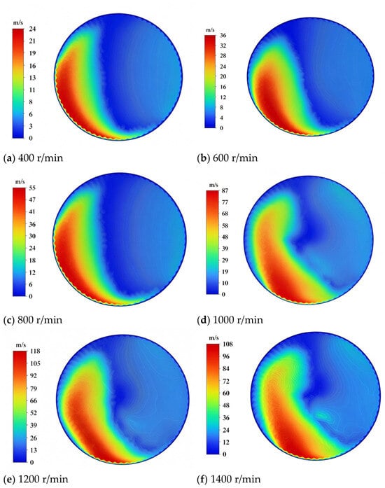
According to Equation (2), whether residual plastic film can be fed into the cylinder depends on the velocities of the inlet airflow and outlet airflow. At the same rotational speed of the moving cutter, the air pressure inside the cylinder is in an equilibrium state: the outlet airflow rate is equal to the inlet airflow rate, and the ratio of airflow velocities is reciprocal to the ratio of flow cross-sectional areas. To obtain the distribution of inlet and outlet airflow fields at the feeding port of the cylinder and further derive the velocity ratio between the two airflows, a simulation of airflow distribution at the feeding port before material feeding is performed in ANSYS Fluent 2022R2. Taking the rotational speed of the moving cutter as the variable, six speed conditions are set: 400 r/min, 600 r/min, 800 r/min, 1000 r/min, 1200 r/min and 1400 r/min. Because the steady-state simulation is deterministic, the reported value at each condition is the converged solution; the error bars in the figures denote the spatial fluctuation of velocity across different sampling positions of the feeding port rather than the random error of repeated runs. The following assumptions are made to simplify the calculation: (1) The air inside the cylinder before feeding is an ideal gas with steady-state turbulent flow; (2) The air satisfies the Boussinesq assumption and is treated as an incompressible fluid; (3) The effect of gravity is neglected; (4) Heat exchange through the cylinder wall is not considered. The inlet boundary is set as a pressure inlet, and the outlet boundary is set as a pressure outlet. The ambient pressure is 1.01 × 10⁵ Pa, and all wall boundaries adopt the smooth wall no-slip condition. To facilitate analysis of the magnitude and direction of inlet and outlet airflow velocities at the feeding port, the simulation results are exported as velocity contour plots and vector plots. The contour and vector plots of the airflow field at the feeding port under different moving cutter rotational speeds are shown in Figure 6. Under all rotational speed conditions, the inlet airflow field occupies a large proportion of the feeding port area. The inlet airflow velocity decreases from the edge of the feeding port toward its center, and remains at a low level in the narrow zone adjacent to the outlet airflow field. The outlet airflow field presents an approximately arc-shaped distribution, mainly concentrated on one side of the feeding port, with its velocity also decreasing from the port edge to the center.
Figure 6.
Distribution of airflow field at the feeding port under different moving blade rotation speeds.
The standard k–ε turbulence model with standard wall functions was adopted for the near-wall region. The rotating zone of the moving cutter was modeled using the Multiple Reference Frame (MRF) approach, which is suitable for steady-state simulation of rotating machinery. A mesh sensitivity study was performed prior to the formal calculation: once the mesh number exceeded about 1.2 × 10⁶, the relative change in the average outlet air velocity was less than 1%, so the medium mesh scheme was selected to balance accuracy and efficiency.
As the rotational speed of the moving cutter increases, the area proportion of the outlet airflow field fluctuates within the 400–1400 r/min range, but the overall variation is small and the outlet field occupies about one third of the feeding-port area. The area ratio of the inlet airflow field to the outlet airflow field can be approximated as 2, and the relational expression for the average velocities of the inlet and outlet airflows is expressed as:
v1—average velocity of inlet airflow at the feeding port, m/s; v2—average velocity of outlet airflow at the feeding port, m/s.
According to the design and assembly requirements of the device, the distance between the upper conveyor belt of the conveying device and the cylinder end cover is 0.2 m. The gravitational acceleration is taken as 9.81 m/s2, the air density at normal temperature and pressure is 1.225 kg/m3, the average density of residual plastic film material is 527.57 kg/m3 according to material analysis, and the air drag coefficient is taken as 0.7. Substituting the above data into Equations (2) and (13) yields that the average outlet airflow velocity enabling the residual plastic film mixture to be fed into the cylinder is 56.74 m/s.
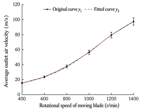
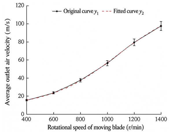
The simulation results are analyzed and sorted to obtain the relationship curve between the average outlet airflow velocity and the rotational speed of the moving cutter, as shown in Figure 7. Numerical analysis of the original curve y1 is conducted in Origin 2024 (OriginLab, Northampton, MA, USA) to derive the fitted curve y2. A two-sample t-test is performed in the same software, with p = 0.27 > 0.05, indicating no significant difference between the fitted values and the actual values. The expression of the fitted curve y2 is given as follows:
Figure 7.
Relationship between average outflow velocity and moving cutter rotation speed.
Substituting the average outlet airflow velocity of 56.74 m/s into Equation (14), the critical rotational speed of the moving cutter is calculated as 999.09 r/min. Further simulation results show that when the rotational speed of the moving cutter is 999.09 r/min and 1000 r/min, respectively, the airflow distribution and average velocity at the feeding port are close, with no significant difference. Therefore, the critical rotational speed of the moving cutter is set at 1000 r/min. Considering the actual working conditions, the rotational speed of the moving cutter must be higher than 400 r/min for residual plastic films to gradually start granulating. Accordingly, the value range of the moving cutter rotational speed is determined as 400–1000 r/min.
2.3.2. Simulation Analysis of Film Cutting Process
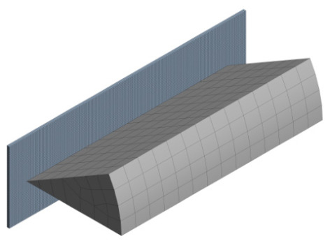
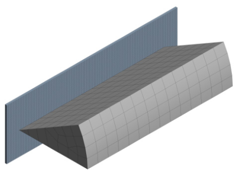
The explicit dynamics software LS-DYNA is mainly used for numerical simulation of high-speed processes such as cutting, impact and explosion. When investigating the relative motion between the fixed cutter and residual film sheets, explicit dynamic simulation can accurately characterize the stress and strain of the fixed cutter and residual film through cumulative calculations of element nodes [15]. For this reason, LS-DYNA was used to simulate the film cutting process. Based on the foregoing theoretical analysis, the edge angle of the fixed cutter is preliminarily identified as the key factor governing the film cutting process, along with its corresponding value range. Therefore, the edge angle of the fixed cutter is taken as the sole variable in the simulation. Following the equal-gradient principle, four edge angles of 30°, 40°, 50° and 60° are selected for simulation cases. During actual film cutting, multiple layers of residual films overlap closely and randomly before being cut by the fixed cutter. Establishing a geometric model consistent with real working conditions would introduce excessive complexity; simulation based on such a detailed model involves massive computational load and fails to cover all parameter combinations. Hence, reasonable simplification of the actual working state is necessary. Moreover, residual plastic film is an ultra-thin, hyper-flexible material. If the penetration displacement per unit time is too large in a single-layer cutting simulation, severe mesh distortion readily occurs, resulting in poor computational stability and numerical divergence. Taking all factors into consideration, an equivalent thickness superposition method is proposed to simplify the residual film model in this study. One hundred layers of residual film are uniformly stacked along the thickness direction to form an equivalent specimen with a total thickness of 1 mm, while only the cutting edge portion of the fixed cutter is retained in the cutter model. Geometric models of the residual film and fixed cutter are established in SolidWorks 2024 (Dassault Systèmes, Vélizy-Villacoublay, France) according to the above simplification scheme. The models are exported in XT format and imported into LS-DYNA. Fine meshing is implemented on the equivalent residual film to guarantee clear fracture visualization. The mesh sizes of the fixed cutter and equivalent residual film are set to 4 mm and 0.2 mm, respectively, with a total element count of 16,724 and a total node count of 25,773; the 0.2 mm film mesh gives five elements through the 1 mm thickness. The simulation model and meshing layout are presented in Figure 8.
Figure 8.
Mesh generation of the fixed cutter and the equivalent residual film (cutter mesh 4 mm, film mesh 0.2 mm; 16,724 elements and 25,773 nodes).
Material tests and the literature review show that the fixed cutter is made of 45 steel (Chinese grade GB/T 699), with a density of 7850 kg/m3, elastic modulus of 205 GPa, yield strength of 355 MPa, and Poisson’s ratio of 0.290 [22]. The residual film has a single-layer thickness of 0.01 mm; its Poisson’s ratio is 0.42, Young’s modulus is 2.415 × 10⁷ Pa and density is 910 kg/m3. The equivalent residual film was described by an elastoplastic material model with kinematic hardening (*MAT_PLASTIC_KINEMATIC), which accounts for plastic hardening beyond the elastic regime; the yield stress and tangent modulus were taken from the material tests of the residual film. A maximum equivalent plastic strain failure criterion was applied: when the equivalent plastic strain of an element reached 0.35, the element was deleted to reproduce the fracture of the film, while the fixed cutter was modeled as a rigid body. According to the foregoing analysis and design requirements, the maximum rotational speed of the moving cutter is 1000 r/min, the inner radius of the granulation cylinder is 0.36 m, and the edged section of the fixed cutter is 0.085 m long. Accordingly, the distance between the fixed cutter edge and the rotation center of the moving cutter is 0.3175 m. The calculation formula for the maximum impact velocity of residual film is given as follows:
vc—velocity of residual plastic film, m/s; nmax—maximum rotational speed of the moving cutter, r/min; r3—distance between the edge of the fixed cutter and the rotation center of the moving cutter, m; the constant 60 converts revolutions per minute into revolutions per second.
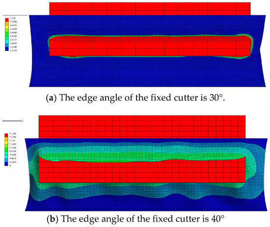
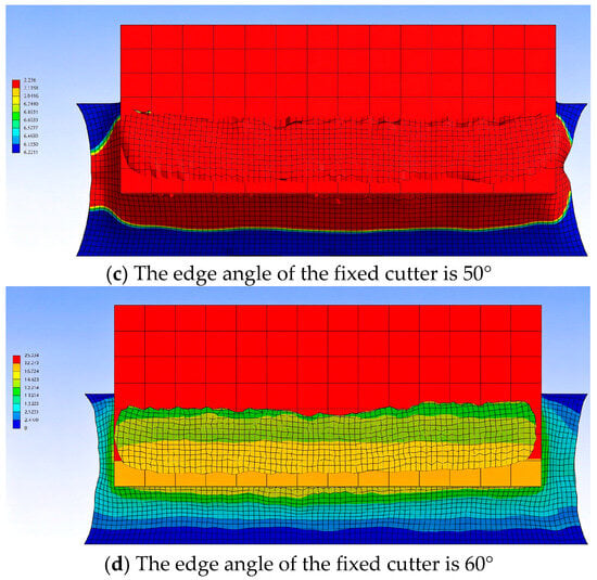
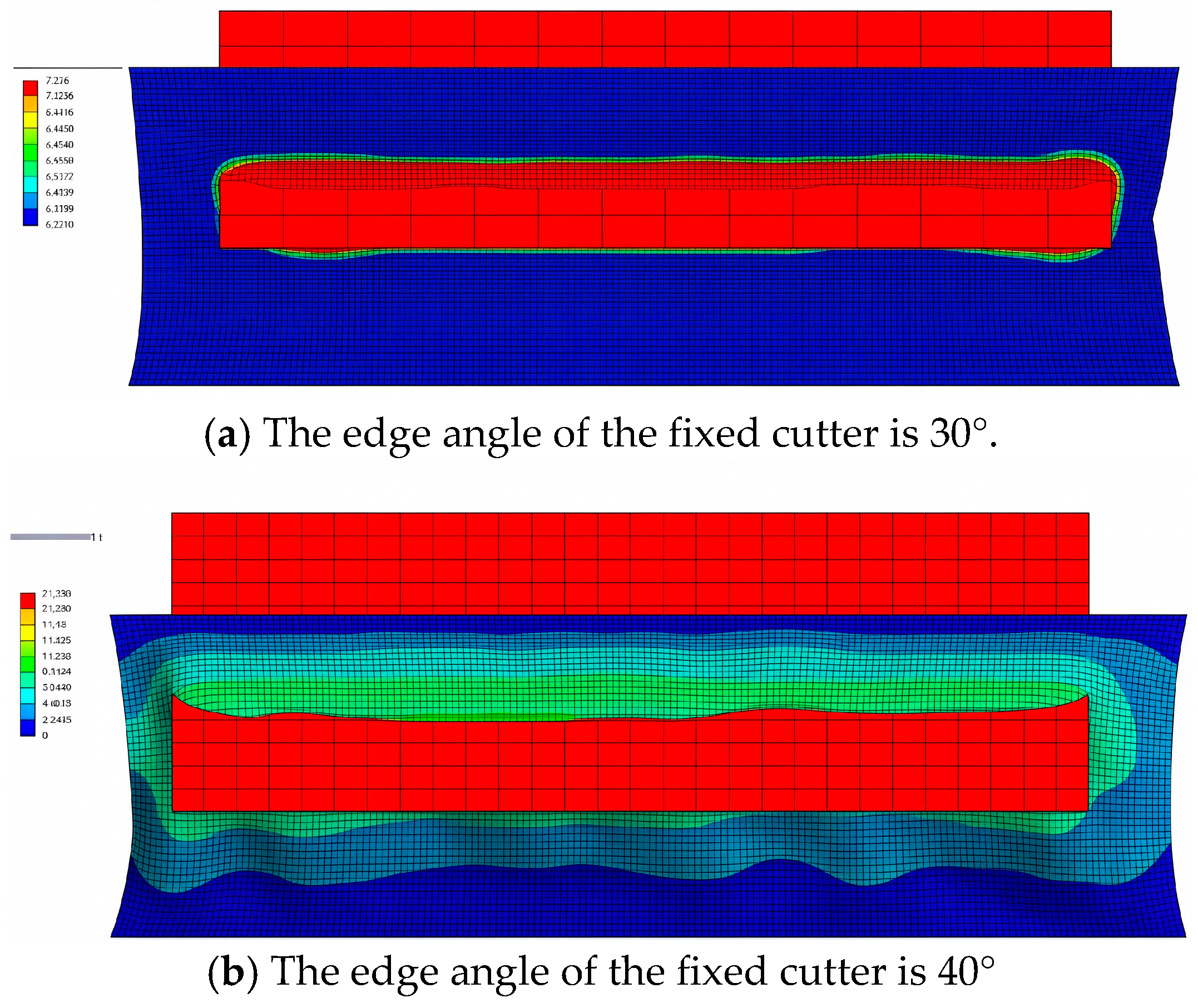
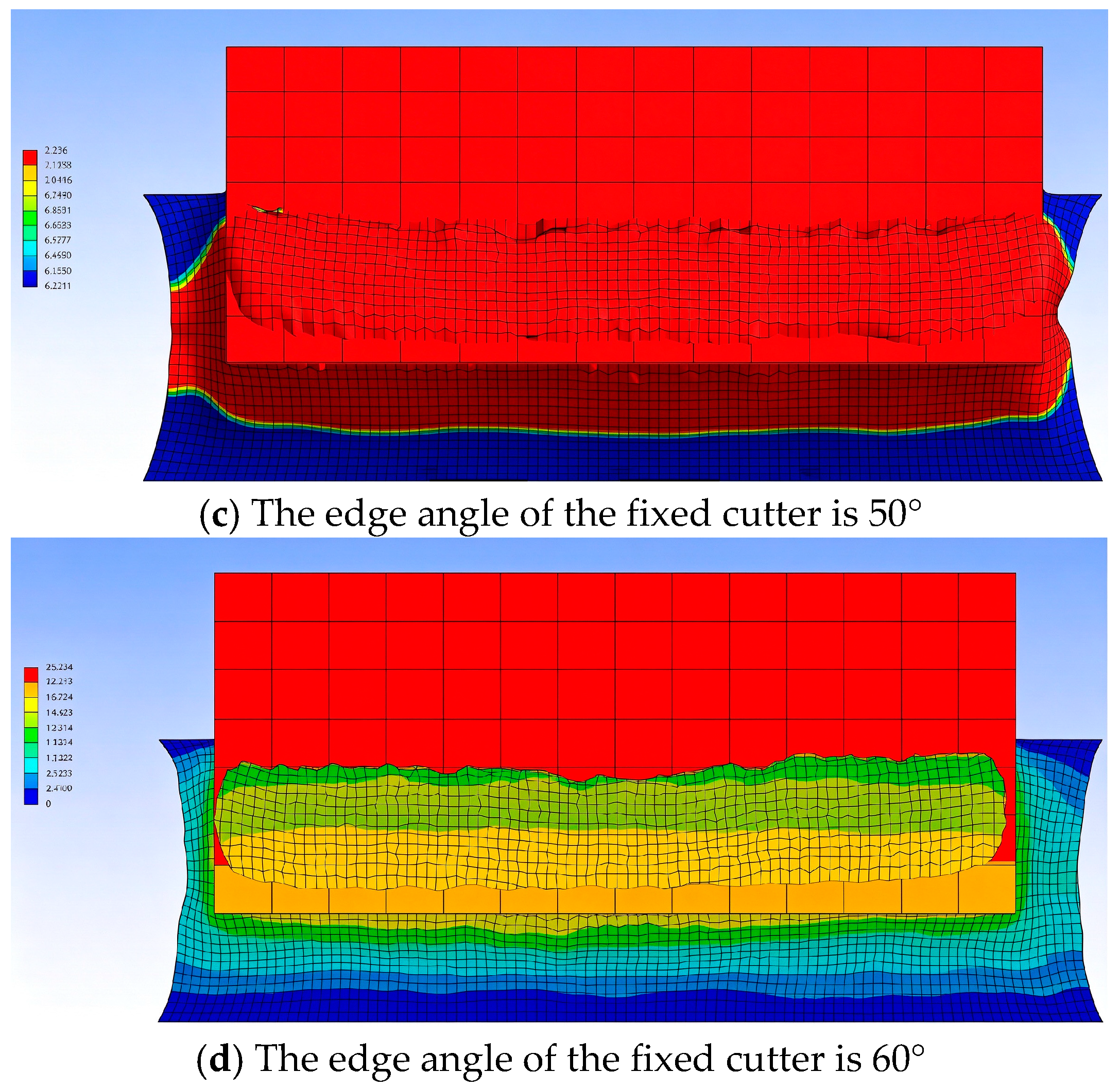
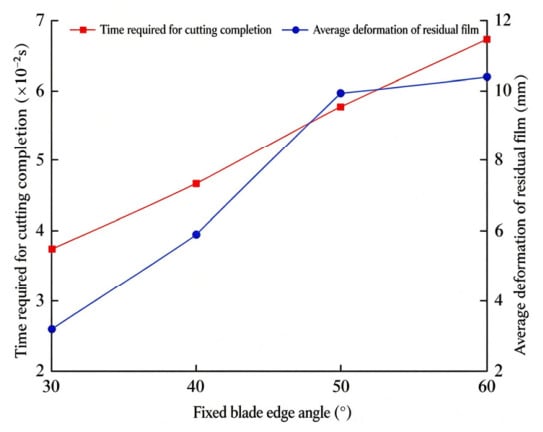
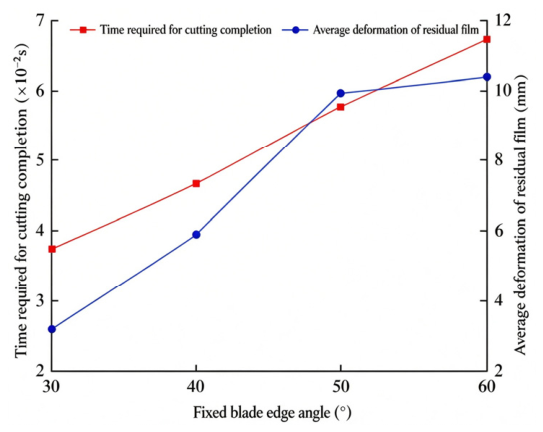
Substituting the above parameters into Equation (15), the value of vc is calculated as 33.25 m/s. For simulation convenience, the re-established kinematic reference frame mentioned above is adopted, where the fixed cutter is assumed to cut the residual film at a velocity of 33.25 m/s. The simulated deformation results of equivalent residual films cut by cutters with different edge angles are illustrated in Figure 9. At the same simulated time (0.001 s), the influence of the fixed cutter edge angle on the deformation and fracture characteristics of the residual film follows a non-monotonic rule. When the edge angle is 30°, the maximum deformation at the residual film crack is approximately 7.3 mm. As the edge angle increases to 40°, the deformation grows to 9.9 mm with obvious crack propagation. When the edge angle further rises to 50°, the maximum deformation at the crack drops back to 7.3 mm. At this time, premature local fractures occur on both sides of the residual film to release stress, thus reducing the deformation in the main crack zone. When the edge angle reaches 60°, the maximum deformation at the crack surges sharply to 14.5 mm, leading to complete separation failure of the residual film. It should be noted that the deformation values quoted above refer to the maximum deformation at the crack tip, whereas Figure 10 reports the average deformation over the whole equivalent specimen; the two quantities are defined differently and therefore differ in magnitude, the former reflecting local crack-tip stretching and the latter the overall deformation of the specimen. In summary, there exists a critical edge angle for the fixed cutter. Below the critical angle, increasing the edge angle mainly strengthens the extrusion and stretching effect, aggravating residual film deformation and crack expansion. After reaching the critical angle, local fractures of the residual film release loads and reduce deformation. When exceeding the critical angle, the excessively large edge angle drastically weakens the cutting performance, with extrusion tearing becoming the dominant failure mode, which sharply intensifies the overall deformation and complete separation of the residual film.
Figure 9.
Simulation deformation results of cutting equivalent residual film with different edge angles.
Figure 10.
Average fracture time and deformation of equivalent residual film cut by fixed cutter with different edge angles.
The data analysis module of LS-DYNA is used to extract the fracture time and average deformation of the equivalent residual film cut by fixed cutters with various edge angles. The extracted data are imported into Origin to plot Figure 10. It can be observed from the figure that the cutting completion time rises remarkably with the increase in the fixed cutter edge angle, which indicates a gradual reduction in cutting efficiency. Meanwhile, the average deformation of the residual film increases obviously, demonstrating that a larger edge angle contributes to enhanced spreading and tearing effects. A too-small edge angle delivers high cutting efficiency yet insufficient spreading and tearing capacity; an excessively large edge angle achieves strong tearing performance but suffers from extremely low cutting efficiency. In conclusion, fixed cutter edge angles ranging from 40° to 50° provide a favorable balance between cutting efficiency and spreading-tearing performance, which better satisfies the practical requirements of residual plastic film cutting.
2.3.3. Simulation Analysis of Granule Stirring Process
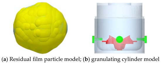
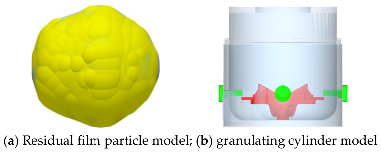
The granule stirring process refers to the procedure where stirring blades agitate residual plastic film particles to accelerate internal heat transfer. During stirring, residual film particles are subjected to complex variable forces that change with particle position, including airflow thrust generated by the moving cutter, contact force exerted by stirring blades, and elastic contact force between particles. Consequently, theoretical analysis of this process is difficult to implement. To facilitate research, EDEM 2022.2 is adopted to simulate the stirring behavior of residual plastic film particles [23]. Based on theoretical analysis and preliminary test results, the stirring efficiency of residual film particles is mainly determined by the lateral area of stirring blades. The lateral area is adjusted indirectly by changing the upper end length of the stirring blades. The maximum upper end length l of the stirring blade is set to 150 mm, and the lower end length remains fixed at 150 mm. Measurement results show that the particles produced by the dry granulation device are irregular spheres. The projected area of the particles was measured by image analysis and converted to the diameter of a circle with the same area, which gave an average equivalent diameter of 2 mm, and a representative irregular outline was taken as the particle shape. The geometric model of residual film particles is established in SolidWorks and exported in STL format, which is imported into EDEM as the particle template for particle filling. The particle size distribution follows a normal distribution with a standard deviation of 0.1; the residual film particle model is shown in Figure 11a. The overall model of the dry granulation device for residual plastic film established in SolidWorks is imported into the software. To simplify the model and improve simulation efficiency, auxiliary components such as the transmission system are removed, and only key components including the cylinder, moving cutter and fixed cutter are retained to form the granulation cylinder, whose individual parts are combined into an integrated model, as presented in Figure 11b. The residual plastic film particle material is defined as a self-customized material, while the granulation cylinder is made of 304 stainless steel with excellent wear and corrosion resistance. According to the actual operating motion of the equipment, a constant rotational motion with a speed of 800 r/min is applied to the moving cutter inside the granulation cylinder.
Figure 11.
Simulation model.
According to material tests and previous research results of the research group, the simulation parameters are listed in Table 1. The particle factory generates residual plastic film particles with a total mass of 40 kg at a generation rate of 40 kg/s. The Hertz–Mindlin contact model is adopted for inter-particle contact. The simulation time step is set to 20% of the Rayleigh time step, and the target data saving interval is 0.01 s. The particle generation and natural deposition stage lasts from 0 s to 1 s, while the rotation and stirring of particles by the moving cutter starts at 1 s and ends at 3 s. The mesh cell size is three times the minimum particle radius. The simulated motion state of residual plastic film particles inside the granulation cylinder is as follows.
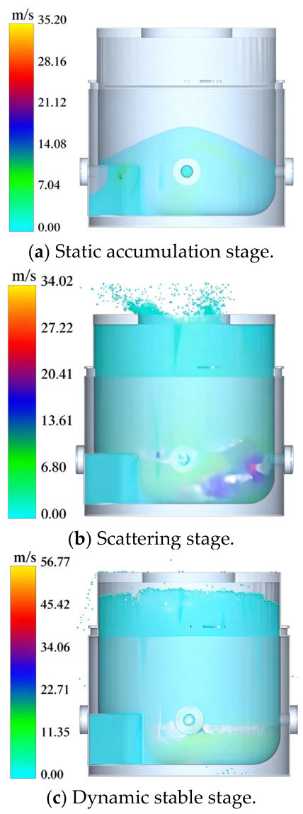
Simulation tests reveal that the stirring process of residual plastic film particles can be divided into three stages: static accumulation, throwing dispersion and dynamic stabilization, as illustrated in Figure 12. From 0 s to 1 s, residual film particles are generated by the particle factory and gradually fill the bottom of the cylinder under gravity, forming tight contact between particles with an instantaneous particle velocity of 0 m/s, as shown in Figure 12a. During 1 s to 1.3 s, part of the residual film particles are thrown upward inside the granulation cylinder. This phenomenon occurs because the particles are densely stacked statically and fully cover the moving cutter. When the cutter begins to rotate, its kinetic energy is intensively transferred to the surrounding particles, enabling the particles to rapidly overcome gravity and inter-particle friction. The maximum velocity of particles around the moving cutter reaches approximately 20 m/s. Without pre-formed flow passages, particles scatter randomly inside the cylinder, and the extrusion force generated by the moving cutter cannot be dispersed, thus pushing particles upward at a velocity of around 6 m/s, as displayed in Figure 12b.
Figure 12.
Simulation motion state of residual film particles.
As the simulation proceeds beyond 1.3 s, a dynamic circulating flow field of residual plastic film particles gradually takes shape. The kinetic energy of the moving cutter is shared by a large number of flowing particles, and the velocity of particles surrounding the moving cutter stabilizes at approximately 11 m/s, while the particle velocity in the upper-middle section of the cylinder remains below 10 m/s. After stable flow channels are formed, particles cannot acquire sufficient kinetic energy to be thrown upward, as shown in Figure 12c. In summary, during the stirring of residual plastic film particles, a portion of particles will be thrown upward at the initial stirring stage. Once a steady dynamic flow field is established inside the granulation cylinder, residual film particles move circumferentially along the inner wall of the cylinder under the agitation of the stirring blades.
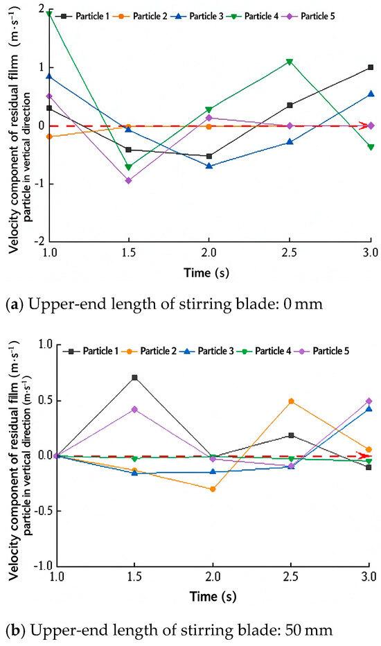
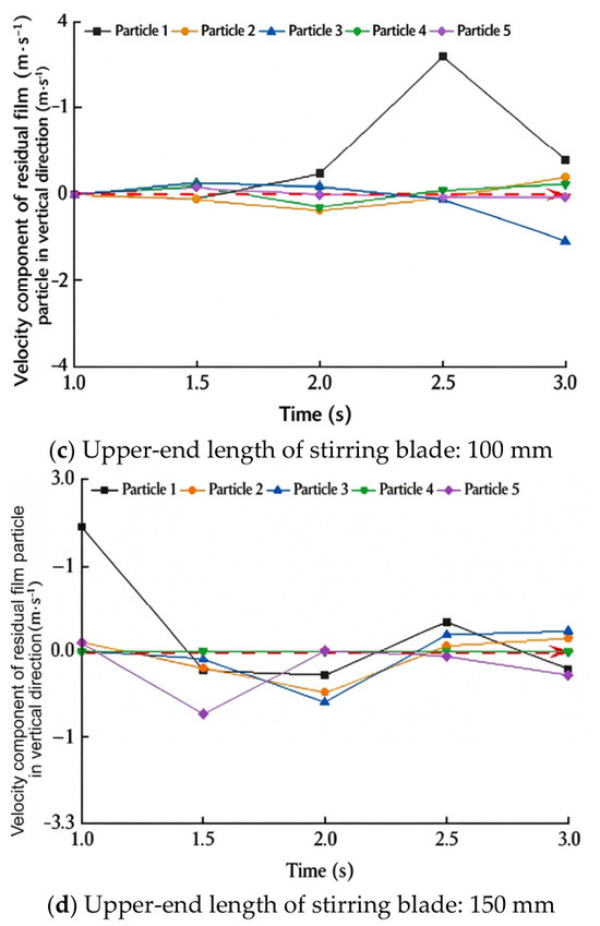
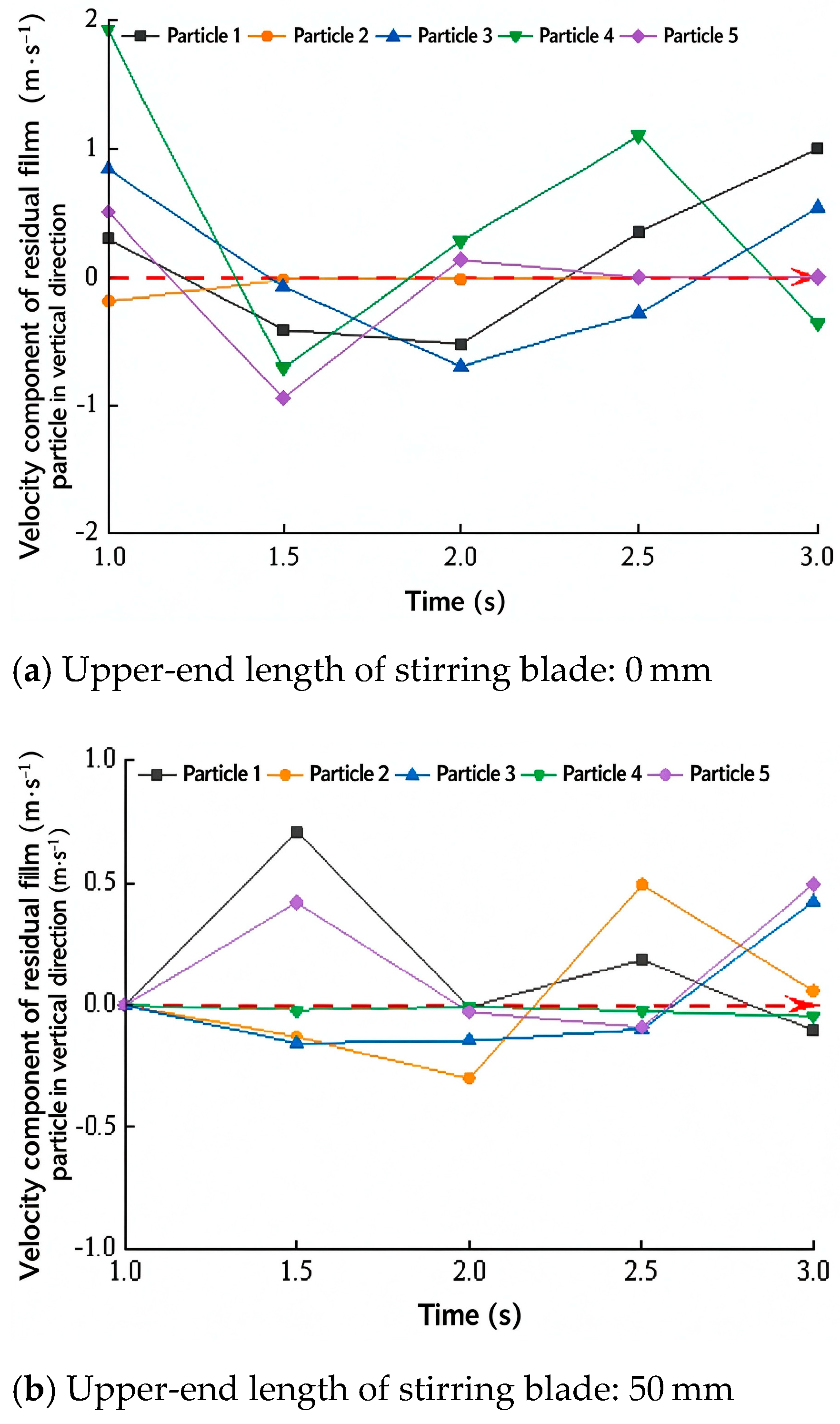
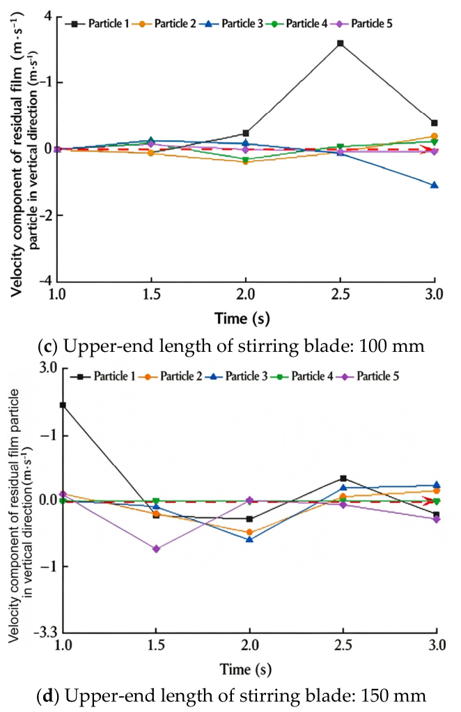
According to the foregoing structural analysis, friction between residual plastic film particles mainly concentrates at the bottom of the cylinder. Particles adjacent to the moving cutter carry the highest heat, while particles at the uppermost layer carry the least heat. The vertical velocity component of residual film particles determines their upward movement tendency: a larger vertical velocity component corresponds to a stronger upward movement and more efficient heat transfer between particles. Therefore, the vertical velocity component is used as an indicator of the stirring performance. The sign convention is defined as follows: the vertical upward direction is positive, and the downward direction is negative. Because the aim of this section is to illustrate the flow pattern rather than to obtain a statistical average over all particles, five tracer particles located at the center and the four corners of the particle factory were tracked, and the curves in Figure 13 are used qualitatively. The quantitative range of l is determined from the theoretical analysis in Section 2.2.3 and the single-factor tests in Section 3.1. Using the post-processing module of EDEM, the vertical velocity components of the tracers under different stirring blade configurations are plotted in Figure 13.
Figure 13.
Relationship between vertical velocity component of residual Film particles and stirring time.
It can be seen from Figure 13a that when the upper end length of the stirring blade is 0 mm, the vertical velocity components of all residual film particles alternate frequently between positive and negative values, accompanied by drastic fluctuations and poor stability. The duration of positive vertical velocity components is short, and the upward movement of particles is easily interrupted. As shown in Figure 13b, when the upper end length of the stirring blade is 50 mm, the vertical velocity components of all particles fluctuate slightly around 0 m/s. Although most of the time the vertical velocity components remain positive to sustain upward motion, the fluctuation range is within 1 m/s, leading to an insignificant upward tendency. The particles mainly move horizontally or vibrate slightly, which fails to realize efficient heat transfer. Figure 13c illustrates the case with a stirring blade upper end length of 100 mm. The positive vertical velocity components of all particles are large in magnitude and long in duration. For Particle 1, the vertical velocity component reaches about 3 m/s at 2.5 s, showing a remarkable upward movement trend. Particles 2 and 5 maintain positive vertical velocity components throughout 1–2.5 s. This group features higher frequency and more prominent positive vertical velocities compared with other working conditions, with more frequent upward particle movement. According to Figure 13d, when the upper end length of the stirring blade is 150 mm, the positive vertical velocity components decay rapidly with weak stability. After 1.5 s, most particles present negative vertical velocity components, indicating obvious downward movement. Although positive vertical velocities appear between 2.5 s and 3 s, their magnitudes are small and the duration is limited. In conclusion, among the four configurations, the upper-end length of 100 mm gives the most sustained positive vertical velocity, whereas 0 mm and 150 mm lead to frequent sign reversal and rapid decay, respectively. Because only five tracers were tracked, these results are used as an illustrative check of the flow pattern rather than as a quantitative criterion; they are consistent with the theoretical range of 75–125 mm obtained in Section 2.2.3, from which the factor levels used in the single-factor tests (Section 3.1) were taken.
2.4. Experimental Research
Experimental Conditions
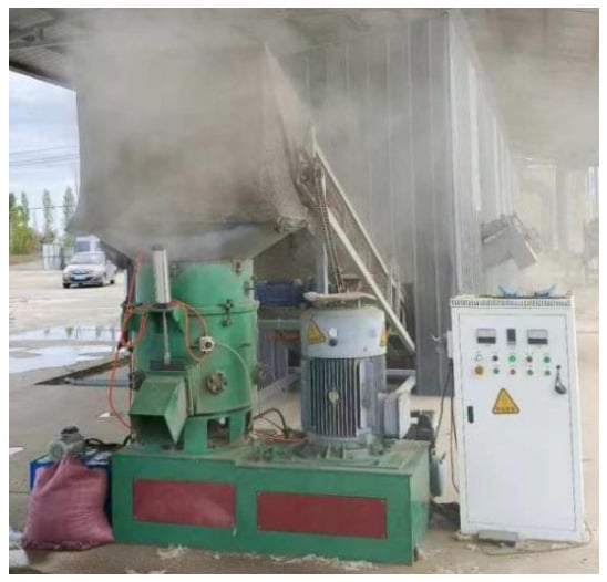
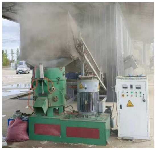
According to theoretical analysis, the performance of the dry granulation device for residual plastic film is mainly affected by the rotational speed of the moving cutter, the edge angle of the fixed cutter and the upper end length of the stirring blade. Prototype tests are conducted to verify the influence of each factor on the granulation performance of residual plastic film and acquire the optimal granulation operation effect, and the prototype is shown in Figure 14. The test material is residual plastic film bales recycled by the combined machine for residual film recovery and straw crushing. After crushing and dry impurity removal treatment, a small amount of dust adheres to the surface of the residual film, and straws and cotton flocks are basically screened out. Essential test instruments are prepared for the experiment, including an electronic scale (full range: 50 kg, precision: 1 g), a timer, woven bags, sample bags, marking pens and other supplies. The purpose of this research is to optimize the relevant internal structure of the residual film dry granulation device on the basis of theoretical analysis and experimental study. While ensuring granulation quality, it intends to raise the utilization rate of residual film and mitigate the phenomenon that residual film is blown away by airflow. Hence, the granulation rate and utilization rate of residual plastic film are taken as the evaluation indices of the experiment. Prior to each test, the test site is cleaned completely and wind prevention measures are implemented to guarantee the accuracy of test results. Equal-mass uniform feeding is adopted in the experiment, and 20 kg of residual plastic film is fed into the cylinder at a feeding rate of 100 g/s.
Figure 14.
Prototype granulation test.
The discharge temperature was set at 125 °C, and the average processing time for each 20 kg batch was about 8 min; the temperature rise was mainly generated by frictional heat between the film and the cylinder wall.
Calculation Method of Residual Film Utilization Rate [24]: Referring to General Principles for Calculation of Raw Material Consumption in Industrial Enterprises and other relevant standards, the total mass of residual film fed into the device is recorded first. Subsequently, all discharged materials are manually collected and weighed to calculate the residual film utilization rate, and the calculation formula is expressed as follows:
Y1—Residual Plastic Film Utilization Rate, %; m1—Mass of residual plastic film particles, kg; m2—Mass of residual ungranulated plastic film, kg; M—Mass of residual plastic film before feeding, kg.
Calculation Method of Residual Film Granulation Rate: Since there are no dedicated standards for residual plastic film particles produced by dry granulation devices, relevant standards for water-washing melt granulation are referred to [25]. Combined with practical production experience, preliminary qualification criteria for granulated residual film are formulated: the equivalent diameter of residual film particles ranges from 1 mm to 3 mm, the 1000-grain weight is between 2 g and 3 g, and no obvious ungranulated film exists in the particle pile. The obtained residual film particles are spread flat on the ground to a thickness of 10 mm. The five-point sampling method is adopted: five sampling points, including four corner points and the intersection of two diagonals, are selected. The spacing between adjacent sampling points is more than 40 mm. Taking each sampling point as the center, a circle with a radius of 20 mm is defined as the sampling area. Residual film particles and ungranulated residual film in each sampling area are manually collected, weighed separately, and then the residual film granulation rate is calculated accordingly. The calculation formula is expressed as follows:
The five-point sampling procedure was adopted to reduce sampling bias. Pre-tests showed that the granulation rate obtained from these sampling points deviated from that of the whole batch by less than 2%, confirming that the sampling areas are representative.
Y2—Residual Plastic Film Granulation Rate, %; m1—Mass of residual plastic film particles in the sampling area, kg; M—Total mass of residual film in the sampling area (granulated particles plus ungranulated film), kg.
3. Results
3.1. Single-Factor Experiment and Result Analysis
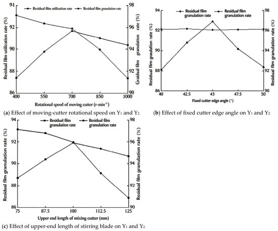
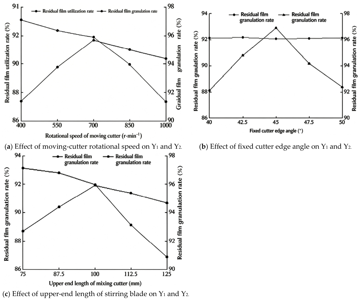
According to the structural characteristics and operation process analysis of the device, single-factor experiments are carried out with the rotational speed of the moving cutter, edge angle of the fixed cutter and upper end length of the stirring blade as influencing factors, so as to explore the variation laws of residual film utilization rate Y1 and residual film granulation rate Y2 with different factor levels. The results of single-factor experiments are presented in Figure 15. Each single-factor condition was tested in triplicate, and the mean value was used; the relative deviations among replicates were below 2%, indicating good repeatability. The repeatability was further quantified from the five center-point replicates of the Box–Behnken design, which give standard deviations of 0.15 and 0.21 percentage points for Y1 and Y2, respectively; these values are comparable to the marker size in Figure 15, so error bars were omitted for clarity.
Figure 15.
Single-Factor Test Results.
As shown in Figure 15a, when the edge angle of the fixed cutter is 45° and the upper end length of the stirring blade is 100 mm, the residual film utilization rate decreases with the increase in the moving cutter rotational speed, while the residual film granulation rate rises first and then declines. Comprehensive analysis indicates that the optimal rotational speed range of the moving cutter meeting the operational performance of the device is 550–850 r/min. It can be seen from Figure 15b that when the moving cutter rotational speed is 700 r/min and the upper end length of the stirring blade is 100 mm, the residual film utilization rate fluctuates slightly as the fixed cutter edge angle increases, whereas the residual film granulation rate increases initially and decreases afterwards. Overall, the preferable edge angle range of the fixed cutter satisfying device operation performance is 42.5–47.5°. According to Figure 15c, under the conditions of moving cutter rotational speed of 700 r/min and fixed cutter edge angle of 45°, the residual film utilization rate goes down with the growth of the upper end length of the stirring blade, and the residual film granulation rate presents a trend of increasing first and then decreasing. Taking all factors into account, the optimal range for the upper end length of the stirring blade to satisfy the working performance of the machine is 87.5–112.5 mm.
3.2. Multi-Factor Experiment and Result Analysis
On the basis of single-factor experiments, response surface methodology experiments were conducted with the rotational speed of moving cutter x1, edge angle of fixed cutter x2 and upper end length of stirring blade x3 as experimental factors, and residual film utilization rate Y1 and residual film granulation rate Y2 as response indices. The coding of experimental factors is listed in Table 2.
Table 2.
Experimental factor coding.
The experimental data were analyzed using Design-Expert software, and the experimental results are shown in Table 3. The residual film utilization rate of the dry granulation device for residual plastic film ranges from 90.22% to 93.66%, with an average value of 92.12%; the residual film granulation rate varies between 90.59% and 96.20%, with an average value of 93.87%.
Table 3.
Response surface test results.
Multiple regression fitting analysis was performed on the experimental results to establish regression models reflecting the relationships between the three variables (rotational speed of moving cutter, edge angle of fixed cutter, upper end length of stirring blade) and the two response indices (residual film utilization rate, residual film granulation rate). Analysis of variance (ANOVA) was conducted for the obtained models, and the results are summarized in Table 4.
Table 4.
Analysis of variance.
For the residual film utilization rate (Y1), the model statistics are R2 = 0.9842, adjusted R2 = 0.9639, predicted R2 = 0.844, and CV = 0.19%. For the residual film granulation rate (Y2), the model statistics are R2 = 0.9890, adjusted R2 = 0.9749, predicted R2 = 0.876, and CV = 0.30%.
Retaining the terms that are significant at p < 0.10 (Table 4), the regression equations describing the effects of moving cutter rotational speed, fixed cutter edge angle and stirring blade upper end length on the residual film utilization rate and the residual film granulation rate are obtained as follows:
It can be concluded from the analysis of variance and regression equations that the influencing factors on residual film utilization rate are ranked in descending order of significance as rotational speed of the moving cutter, upper end length of the stirring blade [19,20]. For residual film granulation rate, the order of significant influencing factors is rotational speed of the moving cutter, edge angle of the fixed cutter, and upper end length of the stirring blade.
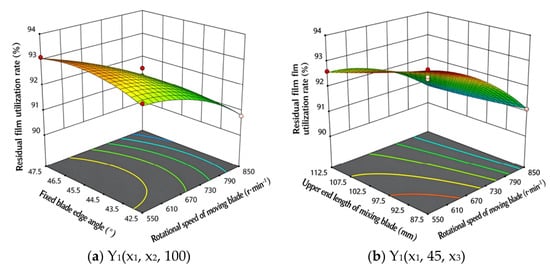
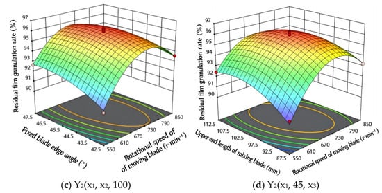
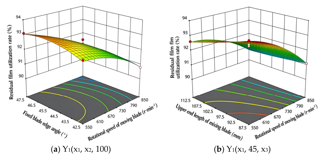
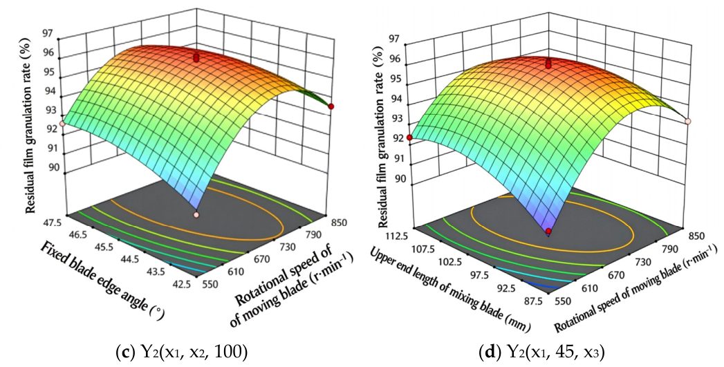
The Design-Expert 13.0 software was adopted to draw response surface diagrams reflecting the effects of significant interactive factors on residual film utilization rate and granulation rate, as shown in Figure 16. Figure 16a illustrates the interaction effect between fixed cutter edge angle and moving cutter rotational speed on residual film utilization rate when the upper end length of the stirring blade is fixed at 100 mm. At a constant rotational speed of the moving cutter, the residual film utilization rate changes slightly with an increase in the fixed cutter edge angle. The reason is that the fixed cutter is mainly responsible for cutting residual film and is closely related to cutting efficiency, while exerting little influence on the internal airflow field of the cylinder. With a fixed cutter edge angle, the residual film utilization rate gradually declines as the moving cutter rotational speed rises. This is because the moving cutter with higher speed produces a stronger disturbance to the outlet airflow inside the cylinder and increases airflow velocity, resulting in a sharp drop in residual film utilization rate. Figure 16b presents the interaction effect between moving cutter rotational speed and stirring blade upper end length on residual film utilization rate at a fixed cutter edge angle of 45°. When the moving cutter rotational speed remains unchanged, the residual film utilization rate decreases with the increase in stirring blade upper end length. Longer stirring blades possess larger lateral area and greater contact area with air; under the same rotational speed, a larger lateral area causes more intense disturbance to the internal air inside the cylinder. When the stirring blade upper end length is fixed, the residual film utilization rate decreases with the rising rotational speed of the moving cutter. Figure 16c shows the interaction effect between fixed cutter edge angle and moving cutter rotational speed on residual film granulation rate with the stirring blade upper end length set to 100 mm. At a constant moving cutter rotational speed, the residual film granulation rate rises first and then falls as the fixed cutter edge angle increases. An excessively small edge angle leads to poor tearing performance for residual film; large-size residual film cannot be fully cut and is difficult to granulate in subsequent processes. In contrast, an overlarge edge angle reduces cutting efficiency, making it impossible to chop all residual film into small fragments within the scheduled time. With a fixed cutter edge angle, the granulation rate increases first and then decreases with rising moving cutter rotational speed. Higher rotational speed accelerates frictional heat generation between residual film and the cylinder inner wall, facilitating granulation. Once the rotational speed exceeds 700 r/min, excessive frictional heat is generated. Meanwhile, the stirring blade has limited capacity for heat transfer to residual film particles, resulting in softening, adhesion and agglomeration of residual film particles at the cylinder bottom. Figure 16d describes the interaction effect between moving cutter rotational speed and stirring blade upper end length on residual film granulation rate when the fixed cutter edge angle is 45°. At a constant moving cutter rotational speed, the granulation rate increases initially and then decreases with the growth of stirring blade upper end length. Moderately lengthened stirring blades enhance stirring and heat dissipation, effectively preventing particle agglomeration. When the upper end length exceeds about 100 mm, excessive stirring and heat dissipation cause rapid heat loss at the cylinder bottom and degrade granulation efficiency. With a fixed stirring blade upper end length, the residual film granulation rate also follows an upward-then-downward trend as the moving cutter rotational speed increases.
Figure 16.
Response surfaces of significant interaction factors on operating performance of the machine.
3.3. Verification Experiment and Result Analysis
To obtain the optimal parameter combination affecting the residual film dry granulation device, a multi-objective optimization analysis was carried out on the rotational speed of the moving cutter, the edge angle of the fixed cutter and the upper end length of the stirring blade, with the objectives of improving the residual film utilization rate and granulation rate. The optimization model is established as follows:
The two responses were combined into a composite desirability function D = √(d1·d2), in which each response was normalized between its observed minimum and maximum in Table 3 and the two responses were given equal weight and importance. Calculation and analysis yield the optimal parameter combination: the rotational speed of the moving cutter is 665.86 r/min, the edge angle of the fixed cutter is 45.58°, and the upper end length of the stirring blade is 97.24 mm. Under this set of parameters, the residual film utilization rate reaches 92.77%, and the residual film granulation rate is 95.58%.
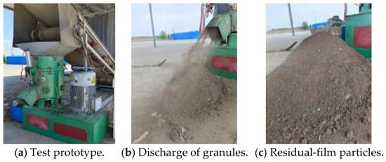
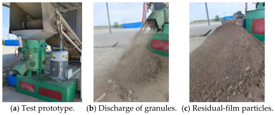
To verify the operational performance of the device, prototype verification tests were conducted at the closed-loop residual film treatment demonstration base in Fangcaohu Regiment of the 6th Division, Xinjiang Production and Construction Corps. Photos of the prototype test and prepared residual film particles are presented in Figure 17.
Figure 17.
Prototype verification test.
After fully considering the rationality and feasibility of the experimental parameters, the optimized parameter combination was adjusted to a moving cutter speed of 666 r/min, a fixed cutter edge angle of 46°, and a stirring blade upper end length of 97 mm. The verification experiment was repeated five times, and the average values of the test results were adopted, as listed in Table 5. Under the optimized parameters, the average residual film utilization rate and granulation rate obtained from verification tests were 91.71% and 94.08%, with relative errors of 1.14% and 1.57% compared with the predicted values, respectively. The standard deviations of the five verification tests were 0.56% for the utilization rate and 1.83% for the granulation rate. The results indicate that the established regression model possesses favorable reliability and prediction accuracy [21].
Table 5.
Prototype verification test results.
To quantify the improvement, the optimized configuration was compared with the pre-optimization baseline. At the upper limit of the design speed range (1000 r/min, with the same 45° edge angle and 100 mm stirring blade), the single-factor test gave a utilization rate of about 87.4% and a granulation rate of about 90.3% (Figure 15a). At the optimized setting (666 r/min, 46°, 97 mm), the field verification gave 91.71% and 94.08%, i.e., increases of 4.3 and 3.8 percentage points, while the rotational speed was reduced by one-third. The lower speed weakens the outflow at the feeding port, which is the main cause of film blow-away, and reduces the energy consumption per batch. A limitation of this study is that the whole-particle statistics of the EDEM simulation were not retained, so the stirring analysis in Section 2.3.3 is illustrative rather than statistical; a full-particle analysis and direct measurement of the particle temperature field will be addressed in future work.
3.4. Discussion
The force analysis explains why the edge angle is the key geometric variable of the cutting process: the cutting resistance in Equation (10) grows with sinθ, so a small angle reduces the force but also weakens the tearing of the film, whereas a large angle improves tearing at the cost of cutting efficiency. The cutting simulations reproduce this trade-off: the cutting time increased and the average deformation of the specimen rose as the angle grew from 30° to 60°, while the crack-tip deformation behaved non-monotonically because local fractures release the stress. The airflow simulations show the other side of the problem: the outflow velocity at the feeding port rises almost linearly with cutter speed (Figure 7), so a high speed improves cutting and heat generation but blows film back and lowers the utilization rate, which is consistent with the single-factor results.
Compared with the design study in [11], which reported the structure and the overall performance of the device, the present work links the three structural parameters to the two performance indices quantitatively. The regression models show that the speed is the dominant factor for both indices (F = 337.04 and 58.14), followed by the blade length for Y1 and by the edge angle and blade length for Y2, and that the interactions speed × edge angle and speed × blade length are significant. The optimum therefore does not maximize either index alone: it reduces the speed by one third relative to the original 1000 r/min setting, which limits blow-back and energy consumption, while keeping the granulation rate above 94%. These trends agree with the general experience that dry granulation depends on a balance between frictional heat generation and residence time [11,18].
The study has several limitations. The EDEM analysis tracked five tracer particles and is therefore illustrative rather than statistical; a whole-particle analysis would require the original simulation database, which was not retained. The tests used one film type collected in one region, and the device operates in batches, so the cylinder must cool between batches. The regression models are local quadratic approximations valid within the tested ranges (550–850 r/min, 42.5–47.5°, 87.5–112.5 mm) and should not be extrapolated. Future work will address full-particle statistics, continuous operation and multi-region field tests.
4. Conclusions
(1) The feeding, cutting and stirring processes of the residual-film dry granulation device were analyzed, and the moving-cutter rotational speed, the fixed-cutter edge angle and the stirring-blade upper-end length were identified as the controlling structural parameters. The derived cutting-force model, Ff = μFn2 + 0.5kl22sinθ, shows that the cutting resistance increases with the edge angle and with the square of the film thickness, which explains why the edge angle must be kept within a moderate range.
(2) The simulations gave the ranges of the three parameters: the critical speed for feeding was about 1000 r/min (range 400–1000 r/min), edge angles of 40–50° balanced cutting efficiency and tearing, and a stirring-blade upper-end length of about 100 mm gave the most sustained upward particle velocity. The three simulations were independent, with no data transferred between the codes.
(3) Single-factor tests narrowed the ranges to 550–850 r/min, 42.5–47.5° and 87.5–112.5 mm. The Box–Behnken models were significant (R2 = 0.984 and 0.989) with non-significant lack of fit; the speed was the dominant factor for both indices, followed by the blade length for Y1 and by the edge angle and blade length for Y2.
(4) The desirability optimum (665.86 r/min, 45.58°, 97.24 mm) predicted Y1 = 92.77% and Y2 = 95.58%, and the field verification gave 91.71% and 94.08% (relative errors 1.14% and 1.57%). Compared with the original 1000 r/min operating point, the optimized setting raises the two indices by 4.3 and 3.8 percentage points at one-third lower speed. The main limitations are the use of five tracers in the EDEM analysis and the single film type and region; full-particle statistics and multi-region tests remain for future work.
Author Contributions
Conceptualization, C.L. and Y.Y.; methodology, M.Y.; software, M.Y.; validation, M.Y. and W.M.; formal analysis, M.Y.; investigation, M.Y. and W.M.; resources, C.L.; data curation, M.Y.; writing—original draft preparation, M.Y.; writing—review and editing, Y.Y. and Y.L.; visualization, M.Y.; supervision, C.L. and Y.L.; project administration, C.L.; funding acquisition, C.L. All authors have read and agreed to the published version of the manuscript.
Funding
This research was funded by the Innovation Project of Xinjiang Academy of Agriculture and Reclamation Science: Platform Construction Project for the Pilot-scale Test Base of Modern Agricultural Machinery and Equipment, grant number NCG202611.
Institutional Review Board Statement
Not applicable.
Informed Consent Statement
Not applicable.
Data Availability Statement
The original contributions presented in this study are included in the article. Further inquiries can be directed to the corresponding authors.
Acknowledgments
We sincerely acknowledge the financial support from the aforementioned funding agencies. We also thank the anonymous reviewers for providing critical comments and suggestions that improved the manuscript.
Conflicts of Interest
The authors declare no conflicts of interest.
References
- Yang, X.; Niu, C.; Shi, J.; Lian, X.; Zhang, S.; Wang, H.; Wang, X.; Hu, C.; Zhang, H. Lightweight YOLOv11n model for efficient and accurate residual-film detection in cotton fields of arid regions. Comput. Electron. Agric. 2026, 249, 111874. [Google Scholar] [CrossRef] [Scilit]
- Han, Y.; Xu, L.; Huang, P.; Lu, L.; Sun, M.; He, C.; Wang, J.; Cao, Y.; Li, Y.; Yan, Y. The effect of adding residual humic acid biodegradable film on agronomic performance of potted tomato under greenhouse conditions. Hortic. Plant J. 2026, 12, 1386–1402. [Google Scholar] [CrossRef] [Scilit]
- Yang, B. A Study on the Impact of Environmental Regulation on Cotton Farmers’ Plastic Film Recycling Behavior. Master’s Thesis, Tarim University, Aral, China, 2025. [Google Scholar]
- Liu, X.; Shi, X.; Guo, Z.; Wang, C.; Wang, X. Performance test on roller type residual film recycling machine. Trans. Chin. Soc. Agric. Eng. 2017, 33, 26–31. [Google Scholar]
- Jiang, Z.; Zhang, J.; Lin, Y.; Tang, Y. Design and Numerical Simulation Study of Film Rod Reparation Device for Residual Film Recycling Machine. Appl. Sci. 2024, 14, 343. [Google Scholar] [CrossRef] [Scilit]
- Fang, H.; Hu, J.; Chen, X.; Zhang, Q.; Bai, J. DBSCAN-MFI Based Improved Clustering for Field-Road Classification in Mechanical Residual Film Recovery. Agriculture 2025, 15, 1651. [Google Scholar] [CrossRef] [Scilit]
- Pan, H.; Dai, F.; Zhao, W.; Zhang, S.; Shi, R.; Song, X.; Zhou, H.; Wang, F.; Chen, J. Simulation and experiment on the film-picking device of residual film recovery machine in the full-film double-ridge furrow using DEM-MBD coupling. Ind. Crops Prod. 2026, 246, 123321. [Google Scholar] [CrossRef] [Scilit]
- Cao, J.; Gao, X.; Cheng, Z.; Song, X.; Cai, Y.; Siddique, K.H.M.; Zhao, X.; Li, C. The harm of residual plastic film and its accumulation driving factors in northwest China. Environ. Pollut. 2023, 318, 120910. [Google Scholar] [CrossRef] [Scilit] [PubMed]
- Pan, L.; Yang, H.; Xu, H.; Shen, H.; Gu, M.; Luo, W.; Wu, F.; Gu, F.; Ren, G.; Hu, Z. Mechanized Recycling of Residual Film from Typical Ridge and Mulching Crops in China: Current Status, Problems, and Recommendations for Sustainable Agricultural Development. Sustainability 2024, 16, 8989. [Google Scholar] [CrossRef] [Scilit]
- Xu, Z.; Shi, A.; Zhang, M.; Liu, L.; Zhou, Z.; Ding, L. Design and Testing of Air-Separation-Type Tillage Layer Residual Film Recovery Machines. AgriEngineering 2025, 7, 262. [Google Scholar] [CrossRef] [Scilit]
- Lu, C.; Ying, Y.; Wang, J.; Wang, M.; He, Y.; Meng, W.; Lu, Y. Design and experiment of residual film dry granulation device. Trans. Chin. Soc. Agric. Eng. 2026, 42, 46–58. [Google Scholar]
- Kavga, A.; Thomopoulos, V.; Pischinas, E.; Tsipianitis, D.; Nikolakopoulos, P. Design and simulation of a greenhouse in a computational environment (ANSYS/FLUENT) and an automatic control system in a LABVIEW environment. Simul. Model. Pract. Theory 2023, 129, 102837. [Google Scholar] [CrossRef] [Scilit]
- He, X.; Li, M.; Chang, X.; Shang, S.; Wang, D.; Wang, J.; Yang, Z.; Wang, R. Design and experiment of the LS-DYNA-based disk-type peanut root-cutting device. Trans. Chin. Soc. Agric. Eng. 2025, 41, 32–42. [Google Scholar]
- Lai, X.; Li, R.; Wang, M. Analysis and optimization of cutting parameters based on an integrated sugarcane-soil-cutter model. Ind. Crops Prod. 2026, 239, 122459. [Google Scholar] [CrossRef] [Scilit]
- Turan, A.K.; Taşdemirci, A.; Kara, A.; Şahin, S.; Güden, M. Investigation of penetration behavior of combined geometry shells at quasi-static and intermediate strain rates: An experimental and numerical study. Thin-Walled Struct. 2023, 182, 110261. [Google Scholar] [CrossRef] [Scilit]
- Shen, S.; Zhang, J.; Mao, H.; Jiang, Y.; Wang, Y.; Zhou, X.; Liu, X. Discrete element modeling of a cultivated soil-residual film composite and simulation of spatial excavation-throwing kinematics. Comput. Electron. Agric. 2026, 246, 111600. [Google Scholar] [CrossRef] [Scilit]
- Patidar, P.; Soni, P.; Jain, A.; Mahore, V. Modelling soil-rotor blade interaction of vertical axis rotary tiller using discrete element method (DEM). J. Terramech. 2024, 112, 59–68. [Google Scholar] [CrossRef] [Scilit]
- Hao, J.; Yu, H.; Zhao, J.; Li, J.; Ma, Z.; Cai, J. Design and test of wedge drag reduction rotary blade. Trans. Chin. Soc. Agric. Eng. 2019, 35, 55–64. [Google Scholar]
- Karson, J.M.; Manson, R.A.; Hader, J.R. Minimum Bias Estimation and Experimental Design for Response Surfaces. Technometrics 1969, 11, 461–475. [Google Scholar] [CrossRef] [Scilit]
- Wang, T.; Yan, M.; Guo, H. A new regression analysis method: Application of response surface methodology in numerical simulation research. Lithol. Reserv. 2011, 23, 100–104. [Google Scholar]
- Fang, J. A Comparative Study on Experimental Design and Model Estimation in Response Surface Methodology. Master’s thesis, Tianjin University, Tianjin, China, 2011. [Google Scholar]
- Meng, C. Overview and Heat Treatment Methods of 45 Steel. New Technol. New Prod. China 2011, 125–126. [Google Scholar]
- Chen, X.; Wu, S.; Bao, P.; Qiao, X.; Zhu, C.; Wang, W. Design and Experiment of Comb-Type Header for Plot Breeding Wheat Harvester Based on EDEM. Agriculture 2026, 16, 347. [Google Scholar] [CrossRef] [Scilit]
- GB/T 29116-2012; General Principles for Calculation of Raw Material Consumption in Industrial Enterprises. China Standards Press: Beijing, China, 2012.
- GB/T 40006.2-2021; Plastics—Recycled Plastics—Part 2: Polyethylene (PE) Materials. China Standards Press: Beijing, China, 2021.

Disclaimer/Publisher’s Note: The statements, opinions and data contained in all publications are solely those of the individual author(s) and contributor(s) and not of MDPI and/or the editor(s). MDPI and/or the editor(s) disclaim responsibility for any injury to people or property resulting from any ideas, methods, instructions or products referred to in the content. |
© 2026 by the authors. Licensee MDPI, Basel, Switzerland. This article is an open access article distributed under the terms and conditions of the Creative Commons Attribution (CC BY) license.