


Abstract
Lithium-ion battery (LIB) cells are available in various sizes, formats, and chemistries. Should a LIB be exposed to conditions outside its operating parameters, each variation affects the cell failure mechanisms and any resultant fire dynamic. Battery fires can be dynamic events that differ significantly from those solid-, liquid- or gas-based fire curves often used in standard building material fire resistance tests. This preliminary research aimed to investigate how standard building materials, sometimes used as a compartment fire envelope, such as gypsum plasterboard, react when exposed to a dynamic battery fire. The research explored batteries that produced jet fires, could act as projectiles, or produced overpressures when they failed. The results showed that cylindrical cells can travel at significant speeds and distances due to expulsing the cell’s contents through the cell’s vent or ejected end cap. These cells were shown to be capable of piercing plasterboard and remain hot enough to present a fire risk where they fall on the far side of the plasterboard. It was also found that the overpressures produced by failing prismatic cells affected the structural integrity of some building materials. The results show a need for further research into the effectiveness of standard building fire controls when exposed to LIB fires.
1. Introduction
The demand for rechargeable portable devices and the drive to achieve Net Zero has led to batteries being prolific in our lives [1,2]. Batteries are made of an anode and cathode isolated with a separator to form what is known as a jelly roll, which is held in a container of electrolyte. The current main types of rechargeable cells are lithium-ion batteries (LIBs) which are split into two main types; those with various nickel- and cobalt-based cathodes and those with lithium iron phosphate (LFP or LiFePO4) cathodes. The type of container determines a cell’s format, for it will be either a hard case to produce cylindrical and prismatic cells, or a soft case to produce pouch cells [3,4]. There are limited cylindrical cell sizes, currently ranging from 1.5 to 40 Ah, but there is a huge diversity of pouch and prismatic cell sizes. Prismatic cells can range from 10 to 628 Ah, with larger sizes now also being marketed. The way the jelly roll is stacked or wound, along with the variations in shapes that can be achieved with pouch or prismatic cases, means that cells can be made small enough to fit into small gadgets or large enough to form part of the structure of a road vehicle chassis [5].
A battery can comprise a single cell, but batteries are often constructed from multiple cells to achieve higher voltages and power capacities. This means that batteries can be small enough to fit into, for example, earbud headphones or large enough to require containerisation, for instance, in grid-scale energy storage systems. The available variability in size and format of cells means that two batteries of the same capacity and voltage could consist of various cells. For example, a 900 Ah battery could be constructed from 3 × 300 Ah cells, 600 × 1.5 Ah cells or anything in between. The variability in battery construction extends further as multiple chemistries are available for Li-ion cells.
The potential for lithium battery failure leading to fires is well studied [6,7,8,9,10,11,12,13]. The batteries can store a significant amount of energy and contain flammable electrolytes. If they are subjected to conditions outside the normal operating parameters, such as excess heat, overcharge, over discharge, or mechanical disruption, the separator can lose integrity, and internal short circuits between the anode and cathode can occur. This leads to more heat production and escalating separator failure, chemical reactions and electrolyte vaporisation within the cell, known as thermal runaway. In solid-cased cells, the vaporised electrolyte eventually produces sufficient pressure to open the cells’ safety venting. However, thermal runaway will often continue, and the pressure will increase to the point that containment is lost. Pouch cells may burst, and hard cells with a crimp cap or engineered vent may lose the cap or vent cover, or the cell could tear open. The contents of the cell may be ejected almost entirely, and if there is enough heat and oxygen available, ignite, or as in the case of LFP cells, the electrolyte boils off and is vented as a jet of hot, flammable gas, smoke and/or vapour [14,15].
Many fire mitigation strategies are based on standard fires, such as gas, liquid or solid fuel fires [16]. Battery fires are different from fire with other fuels; some studies have looked at developing a standard battery fire model [17,18,19]. However, cells of different capacity and format exhibit different fire behaviour upon cell failure, such as jet fires, delayed ignition of vented flammable gases [8,20]. Cells of the same capacity and format can fail differently due to the state of charge or condition that led to cell failure, and variations in cell chemistry [21]. The variability provides a challenge when considering fire mitigation strategies.
Traditional protection systems that prevent fire spread and damage to a building or structure can be passive or active and are often performance tested to known parameters for general fires, such as cellulose fires [16,22]. The testing generally takes the form of a standard test, such as a propane burner in a sandbox, as specified by a national or international standard [23,24]. Many building materials are certified against the standard tests using a general classification [25]. More specialised systems, such as passive fire protection (PFP), will have more specific international testing standards. These include systems used on offshore oil rigs, which will have been tested against a jet fire or a hydrocarbon fire curve test. They will be certified according to the test results, i.e., how long the system protected the substrate from excessive heat rise. For example, a PFP system that can withstand a 60 min jet fire will be certified as a J60 or an hour hydrocarbon fire, H60 [26,27].
Gypsum plasterboard is well regarded for its ability to withstand fires and is commonly used as a firewall barrier in buildings [28,29]. When exposed to the heat of a fire, the gypsum dehydrates and liberates water; this provides a method of heat absorption and protection from the fire [30]. Gypsum plasterboard has been shown to have good structural integrity during a fire, to a point [31]. However, plasterboard is a low-strength, fragile building material and is prone to impact damage [32]. Battery fires can be dynamic events, with overpressures and moving cells [21]. Meliá et al. [20] showed that battery fires can produce intense jet-fires and with batteries consisting of multiple cells; several jet fires can occur throughout the duration of the battery fire. To be an effective fire barrier, a wall needs to maintain structural integrity; it needs to survive the early stages of a significant battery fire to provide an effective fire envelope. Sauer et al. [33] conducted deflagration experiments with synthesised battery vent gas in a structure representing a domestic garage; damage was observed to the plasterboard drywall caused by the explosions.
Another fire spread prevention strategy is to use separation distances, separating objects so that fire in one will not spread to another. This strategy is often used to protect buildings from external fires [34]. It is also considered when storing flammable material outdoors or undertaking processes near buildings. Understanding the heat output of a potential fire and the size or projection of flames is vital to ensure the separation distance is sufficient to prevent fire spread.
Previous research and experiments have shown a wide range of variability in how batteries fail; even batteries of the same type subjected to the same conditions can exhibit different failure dynamics [21]. This research is intended to act as a preliminary study, experimentally investigating how building materials such as plasterboard may be adversely affected by the consequences of the dynamic nature of battery failure. The aim is to highlight areas that require further research to understand the effectiveness of traditional passive fire protection strategies.
2. Materials and Methods
Three experimental programmes were completed, requiring two experimental rigs. The first programme aimed to understand the distances that cells can travel when they fail in a projectile-like manner. The second programme was to understand if the cells acting as projectiles can penetrate plasterboard walls. These two programmes used the same rig.
The third programme aimed to investigate the effects of battery failure in a small-scale room; this required a different rig that enabled the enclosing of the experiment in building materials.
2.1. Battery Samples
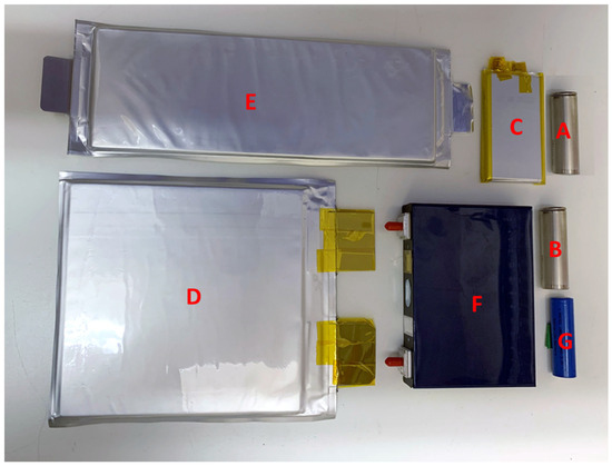
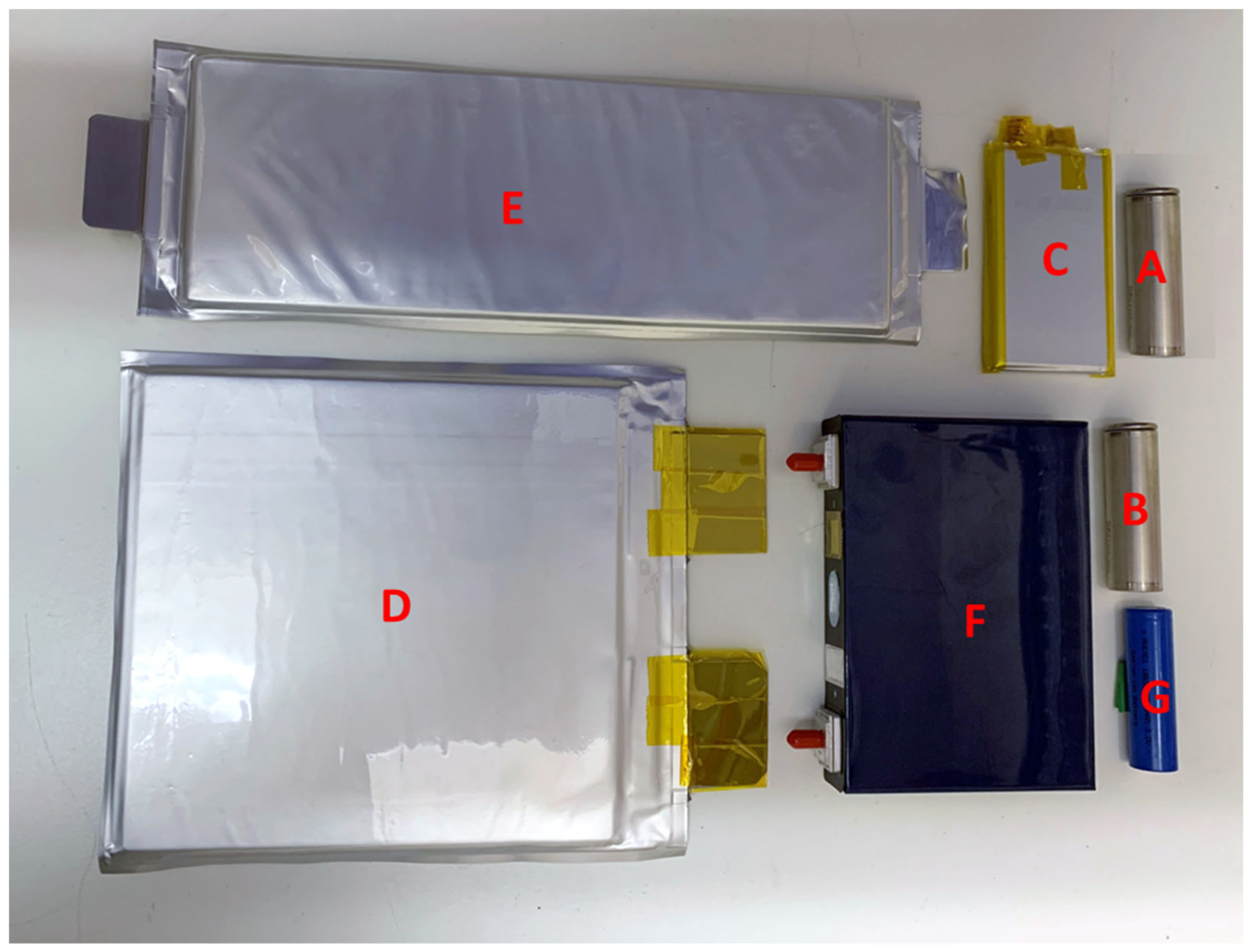
The cells used (Figure 1) are detailed in Table 1. Manufacturers do not always publicise the specific cell chemistry of their products; however, the cells used were either lithium nickel manganese cobalt oxide (NMC) or lithium nickel cobalt aluminium oxide (NCA), with the exception of cell type C which was a blend of NMC and lithium cobalt oxide (LCO). Cell blocks were constructed by attaching the cylindrical cells together using Kapton and glass fibre tape. The cells were new cells and cycled three times before being charged, within the manufactures recommended parameters, to 75% as the starting point for the overcharge experiments or 100% for the external heat experiments. Cell choice was based on how the cells were known to fail during abuse tests within our research.
Figure 1.
Cells used for testing, designated A–G, see Table 1.
Table 1.
Details of battery cells used in experiments.
2.2. Building Materials
Building materials used were all purchased from local building merchants. For plasterboard experiments, 9 mm and 12 mm thick standard BS EN 520-Type A plasterboard was used, with standard finishing plaster to skim the surface. For experiments to simulate a standard construction stud wall, 50 mm × 75 mm carcassing timber was used, for which plasterboard could be attached at both sides. Additional experiments were carried out with 6 mm calcium silicate fireboard and 25 mm polyisocyanurate (PIR) foam with aluminium foil covering.
2.3. Projectile Rig
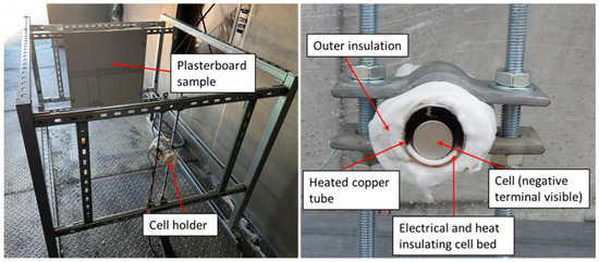
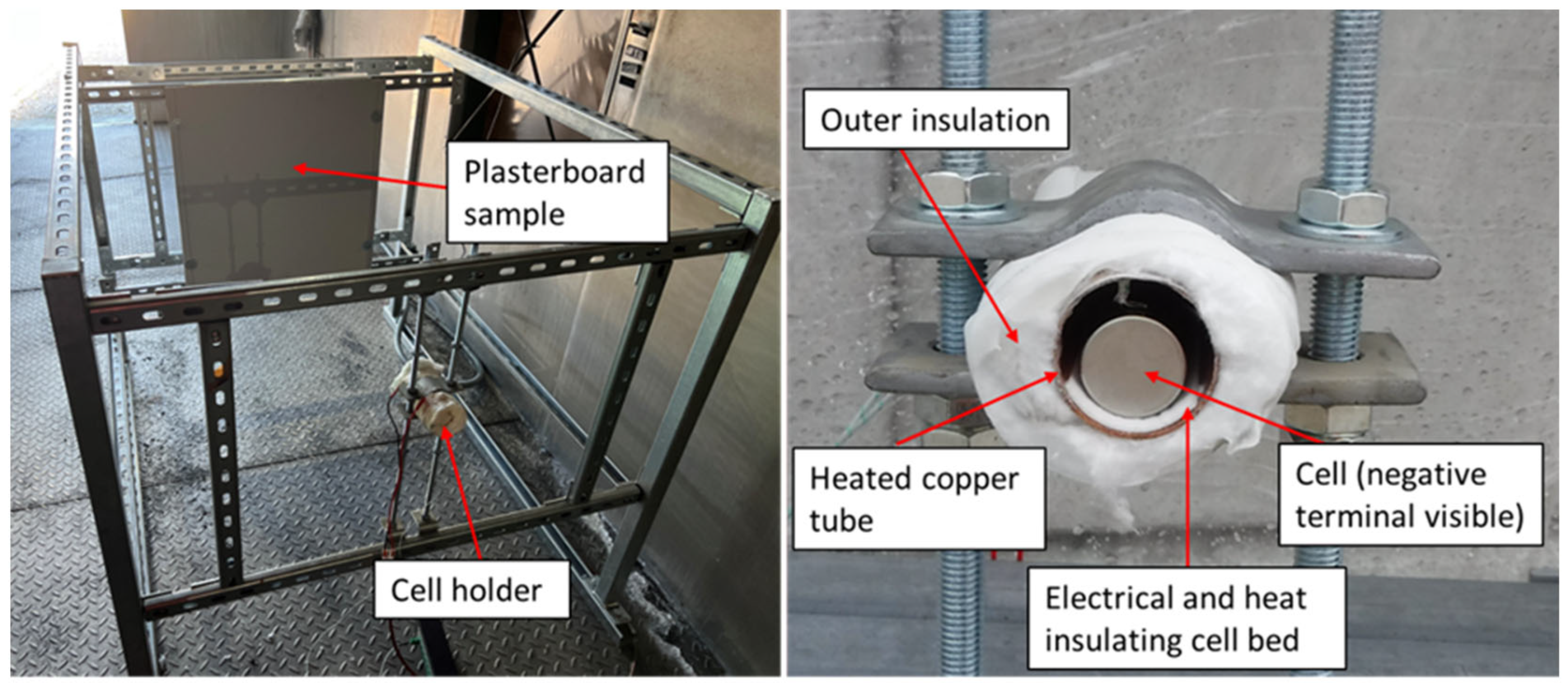
The rig was constructed for two purposes: to allow a cell using the energy released during failure to travel unrestrained in the open field or to be aimed at a plasterboard sample. The rig (Figure 2) was a frame made from channel rail, with a sample holder that could hold 0.6 m2 plasterboard samples. The sample holder could be slid along the rig to change the stand-off distances. To hold the cells without constraining them and provide a method of heating them to failure, a 25 mm diameter capped copper tube was used. The tube was wrapped in 1 m of 0.2 × 0.6 mm Kanthal, Hallstahammar, Sweden, resistance wire and insulating wool and clamped to the frame. The resistance wire was powered with a DC power supply set to deliver 66 W; this was capable of heating a 21 mm diameter, 70 mm long aluminium cylinder to 200 °C within an hour. The cells were placed on a bed of insulating fabric to avoid direct heating and short-circuiting the cell on the copper tube. The open end of the tube assembly was aimed at the plasterboard sample, or, for the open field test, it was turned 180° to allow the cell to travel away from the rig. Tests were recorded with a Phantom, Wrexham, UK, Miro C210 high-speed video camera at 1000 frames per second or a Phantom, Wrexham, UK, V2640 at 5000 frames per second.
Figure 2.
Projectile rig, (left) overview and (right) cell holder.
The start height for open field tests was 0.6 m from the ground. All experiments were initiated remotely from a metal-walled control building; all personnel were inside the control building for the duration of the tests. In addition to high-speed video, wide angle action cameras, filming at a rate of 250 fps and HD video cameras filming at a rate of 25 fps were used in an attempt to track the cells for the open field experiments.
2.4. Building Material Rig
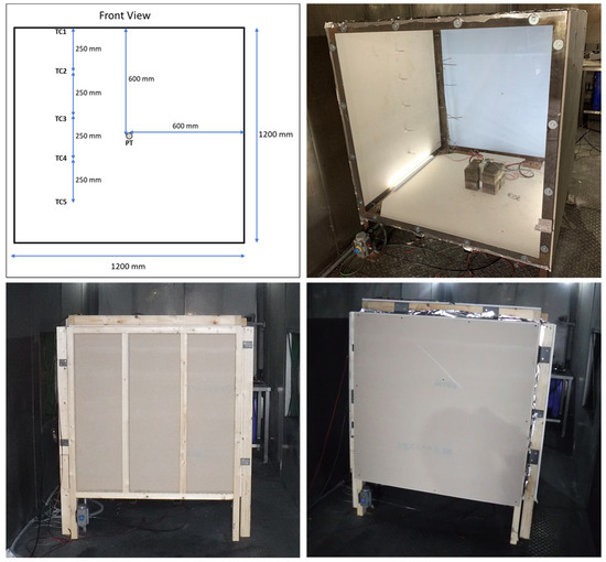
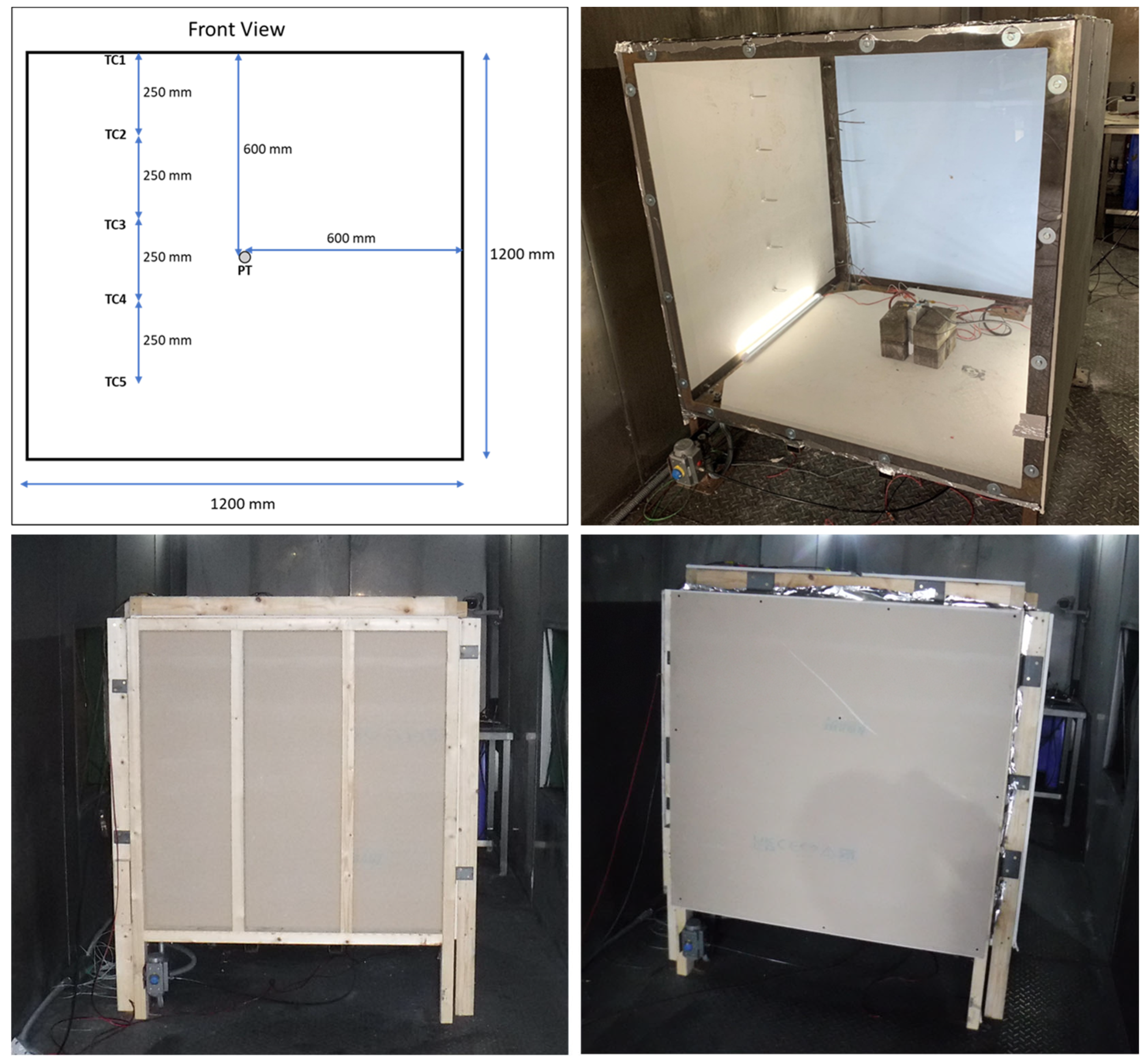
A cube frame rig was constructed using a 50 mm mild steel angle measuring 1.2 m in each direction (Figure 3). The floor was constructed of 3 mm mild steel plate; the front was constructed using 5 mm clear polycarbonate bolted to the frame. For the single-layer plasterboard, fireboard, and PIR foam tests, the building materials were fitted to the outside of the rig with bolts on all sides but the front, which had a transparent polycarbonate cover. For the stud wall experiments, the wall assembly was built around the rig to enclose it fully; as it was self-supporting, it was not attached to the metal rig. The rig with the sides had a nominal volume of 1.728 m3. The rig had an inlet and outlet gas valve to allow purging of the rig post-test; however, the rig was not designed to be gastight. LED strip lights were installed in the rig’s base to illuminate any vent vapours or smoke. The rig was situated in a purpose-built battery abuse testing chamber fitted with a multi-bed filtered extraction system. The chamber has pressure relief panels designed to fail at around 1–2 kPa. All experiments were controlled and monitored remotely from a control room situated 60 m away.
Figure 3.
Building material rig with thermocouple and pressure transducer locations marked, with single layer of plasterboard attached and encased in a stud wall assembly, with one and two layers of plasterboard.
The rig was equipped with a Kulite Semiconductor Products, Inc. Leonia, NJ, USA, 30 psi (206.8 kPa) fast-response pressure transducer in the centre of the back wall. A tree of five 3 mm K-type thermocouples with a grounded tip swaged to a 0.5 mm diameter was present, with the tips facing diagonally 0.25 m from the back corner; the first was at ceiling height and the rest at 0.25 m intervals. Exposed tip K-type thermocouples were attached to the walls inside and out, and to cells when required. High-speed pressure data was recorded on a manually triggered Graphtec Corporation, Yokohama, Japan, GL980 datalogger at a sample rate of 50 kHz. Temperature, high-speed data trigger and voltage data were recorded using a National Instruments National Instruments, Austin, TX, USA, CompactDAQ datalogger at a rate of 1 Hz. Tests were recorded with a Phantom Miro C210 high-speed video camera at 1000 frames per second and standard HD cameras at several angles.
The cells were placed in the rig on a fireboard base; house bricks were used to hold some cells upright without adding constriction to the cell. For overcharge experiments, cables were attached via ring crimps or clamps to the cell terminals with the supplied nuts or bolts, depending on the gender of the terminals. A TDK Lambda Corporation GmbH, Acern, Germany, GenU 1500 W power supply was set to provide a current-equivalent 1 C charge rate at a maximum voltage of 60 VDC (used in a constant current mode), and a contactor was used on the positive circuit to provide a remote operation method for the experiment. For external heat experiments, 4× turns of 0.2 × 0.6 mm Kanthal resistance flat wire was taped to the cells with Farnell, Pheonix, AZ, USA, Pro Power Kapton tape and powered through a contactor to provide 60 W of power.
3. Results and Discussion
A total of 33 tests were carried out between the three types of experiments.
3.1. Overview of Cell Failure Dynamics
The experiments demonstrated that the different formats of cells used in these experiments failed differently. The pouch cells swelled before failure and burst open at the point of failure from one side, emitting a jet flame. The entire cell was involved in the fire, leaving remnants of just the jellyroll in place. The cylindrical cell cap opened, and most of the contents remained in the cell with flames and sparks emitted as a jet, or the entire contents were ejected, burning rapidly outside the cell case, or a combination with partial ejection of the cell contents and jet fire. The prismatic cell top was ripped off at the point of failure, and most of the contents were ejected, burning rapidly outside the cell case.
The different abuse methods were chosen through learning from other experiments as to which method was more likely to produce a failure with fire; in essence, which produced the most violent outcome.
3.2. Open Field Projectile Experiments (Tests 1–8)
Table 2 details the experiments’ results. The experiments aimed to ascertain whether the selected cells were capable of self-propelled flight due to their failure dynamics and to understand the potential distances they can fly. The results show that the cells can travel significant distances due to the ejection of material from the cap end.
Table 2.
Overview of results of open field projectile experiments.
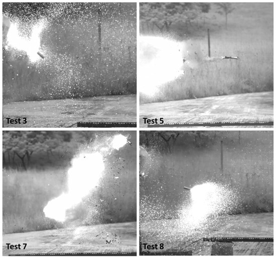
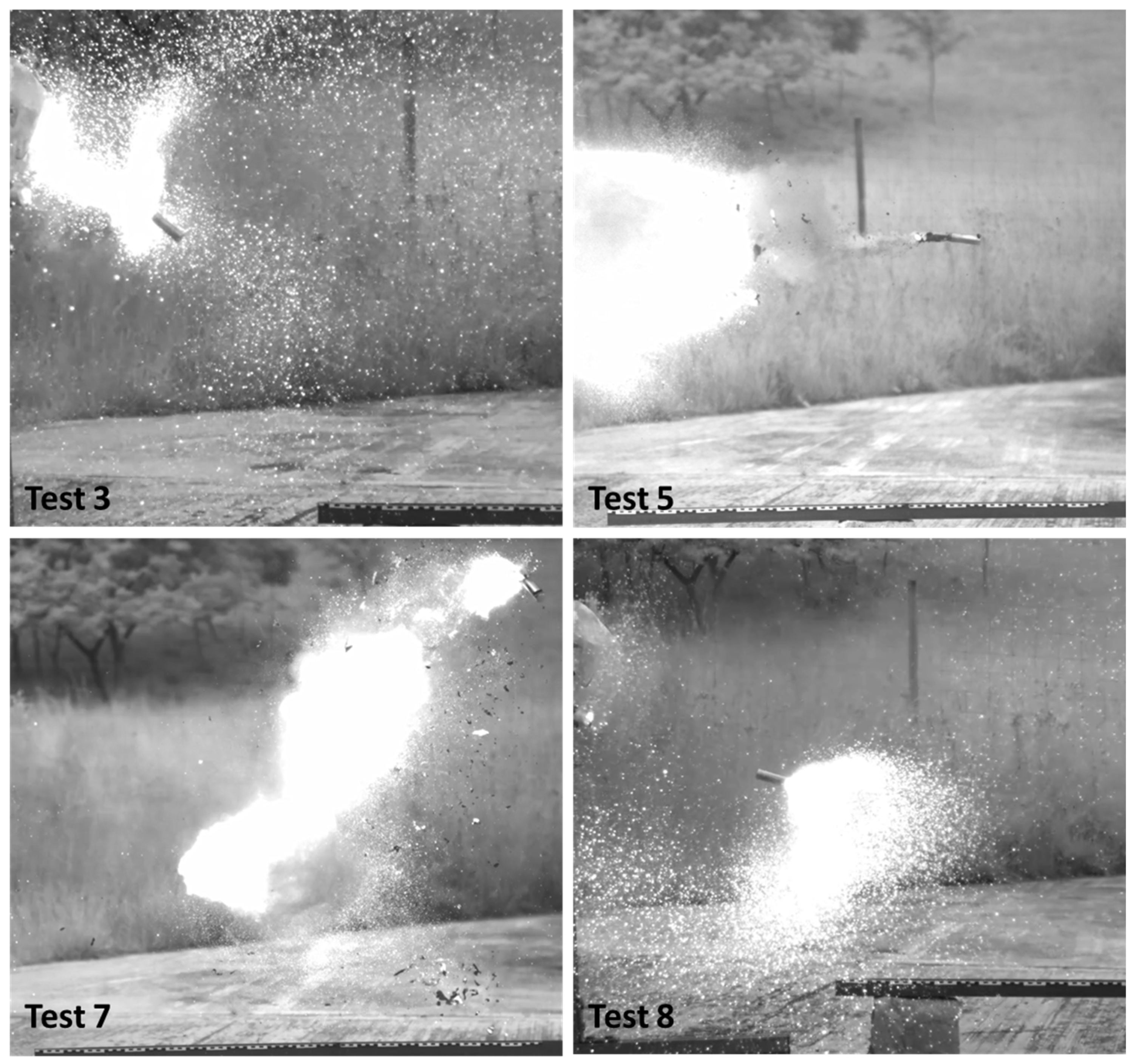
Cell type A is more prone to failure by emitting sparks and a jet fire through the cell vents at the positive terminal. This resulted in an unstable flight, with the cell spinning in the air and the potential for it to land whilst still flaming. Cell types B and G were less predictable; some behaved similarly to Cell A, or the end cap was removed and the contents were entirely or partially ejected. If all the contents are ejected, they are left behind and burn in place; the empty cell case is more likely to have a straight trajectory but will have less mass and cool quickly. If the contents are partially ejected, they can come out at any point during the flight and continue to burn where they fall, as was the case with Test 5 (Figure 4). The loss of portions of material can also change the trajectory and speed during flight; however, in Test 8 the cell emitted sparks but still dramatically changed direction during flight, travelling out of the test arena. In Test 5 the B type cell was clearly observable on the wide-angle camera because it still had a flame as it landed around 32 m from source.
Figure 4.
Examples of cell flight; Test 3 with cell emitting sparks in erratic flight; Test 5, contents left behind and almost empty case in flight; Test 7 with contents ejected during flight; Test 8 cell changing direction in flight.
These experiments and previous group work by Abbott et al. [21] have shown that distance, speed and direction of flight of cells that form projectiles, due to the nature of the failure mechanisms, is unpredictable. Likewise, knowing if the cells are a fire risk when they land is also unpredictable. Observing the results was difficult due to the need to be a significant distance away from the experiment, the small size, and the unpredictable travel of the cells. The cell in Test 5 was observable because the light levels were low and the cell and had a luminous flame throughout the entire flame; however, this also shows that it is possible that cells can travel tens of metres and land on fire.
Except for a limited set of circumstances, such as transportation or pack manufacturing, it would be expected that cells will be restrained in groups attached by busbars, and confined inside a module or battery pack casing; therefore, the experiments are not fully representative of a real-world scenario. However, it is not unforeseeable that the forces generated during cell failure, demonstrated here could lead to sufficient damage to a pack that some cells would become unrestrained during a cascade failure of a battery module or pack.
3.3. Projectile Aimed at Building Material Experiments (Tests 9–20)
These tests were designed to assess if an unrestrained cell failing, can hit samples of plasterboard with sufficient force to damage it or pierce through it; the results are detailed in Table 3.
Table 3.
Results of experiments where cells were aimed at samples of building material.
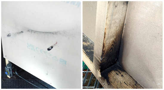
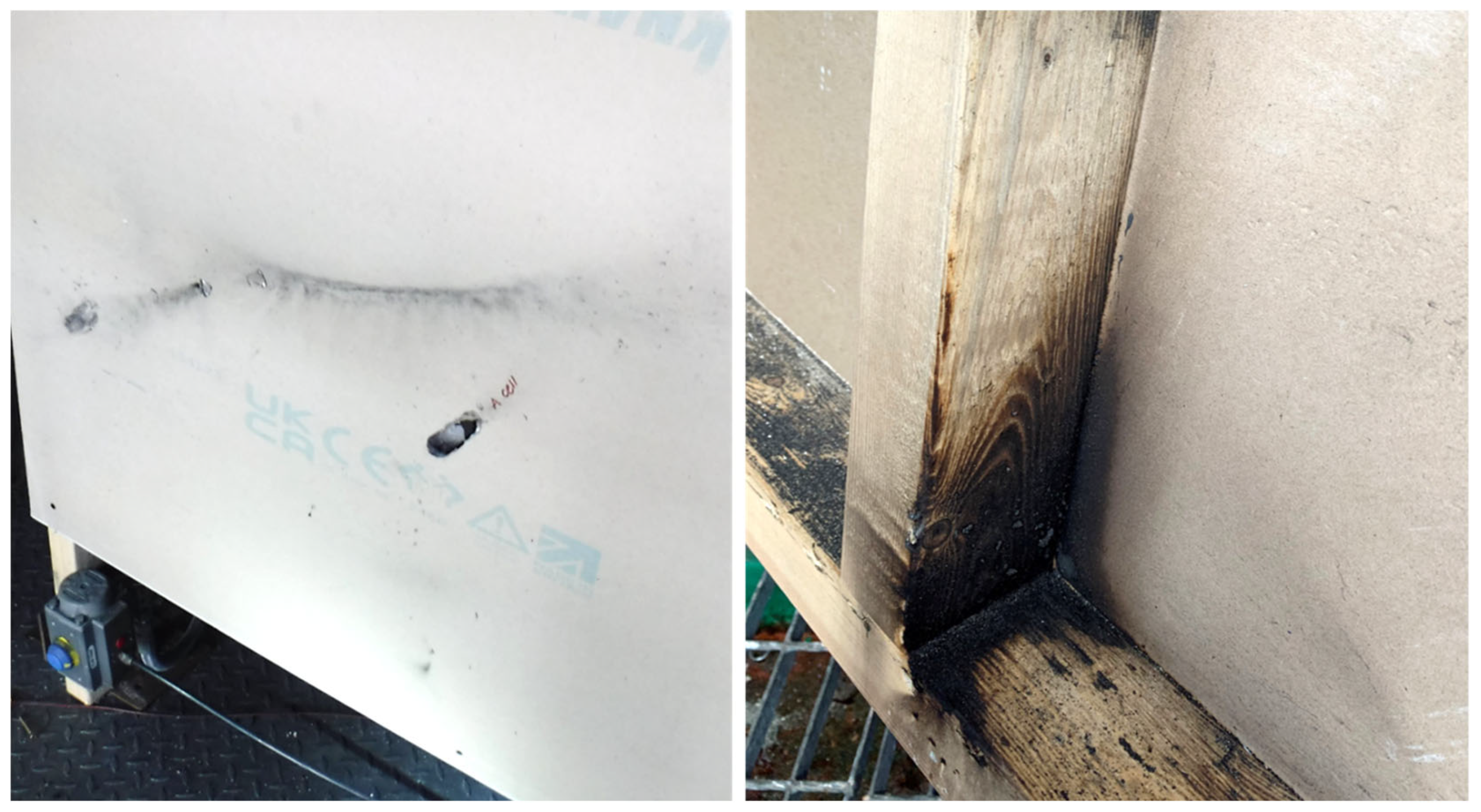
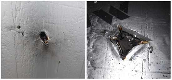
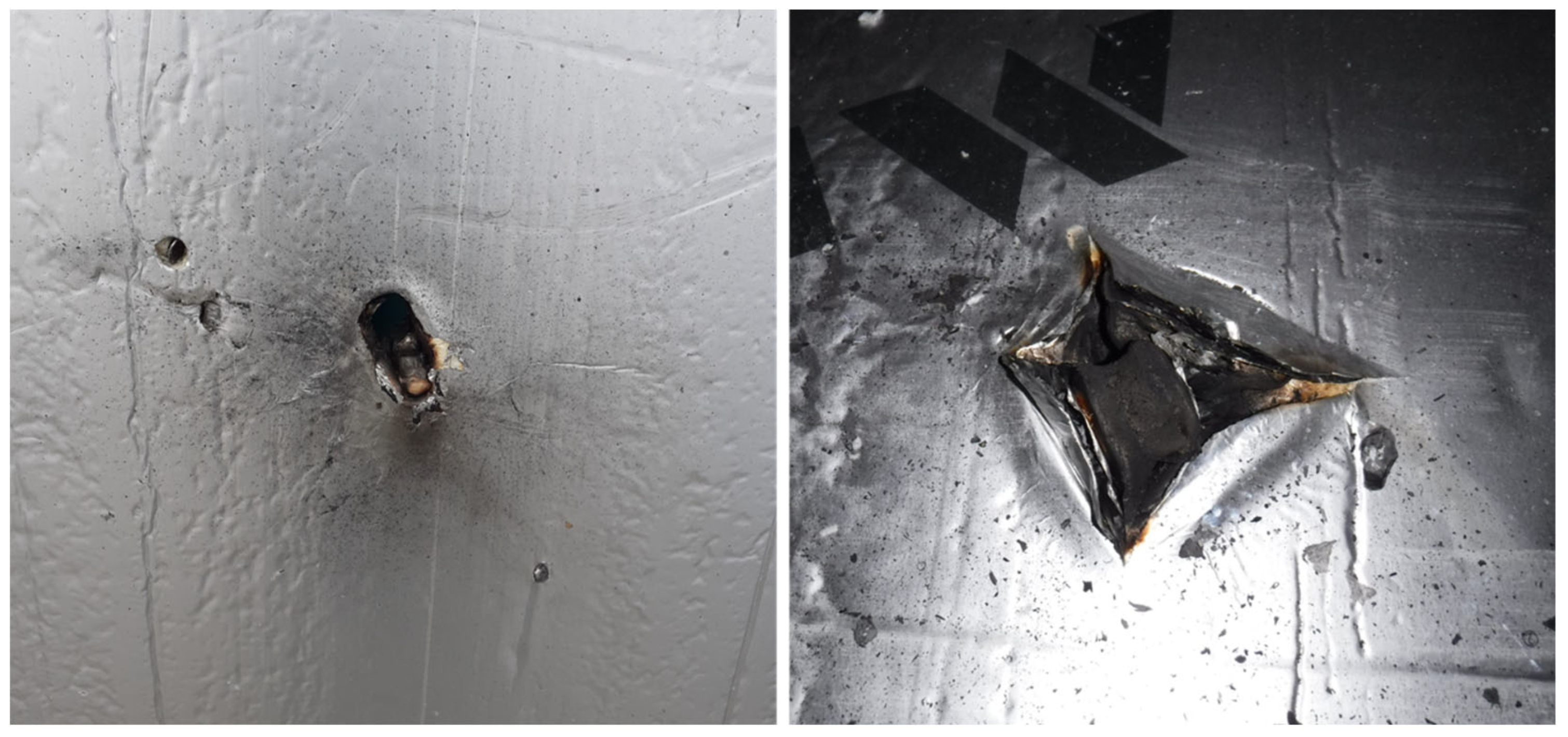
In Test 11, the cell travelled with a reasonably straight trajectory and hit the target with the negative end of the cell (Figure 5). When it hit the plasterboard target, part of the contents was ejected and fell, burning in front of the target. The cell punctured the sample, passing all the way through and continued to travel, still burning, landing 1.6 m away. In Test 12, the cell hit the sample side-on with a much larger impact surface area than in Test 11 and caused a dent in the sample’s surface but did not penetrate. In Test 19, the flight was erratic, and the cell spun across the surface, making glancing contact and leaving scorch marks (Figure 6).
Figure 5.
Test 11—cell after penetrating the sample.
Figure 6.
Tests 19 and 20: (Left) Scorching caused by cell in Test 19 and hole in plasterboard and (right) charring to wooden stud behind first layer of plasterboard caused by cell in Test 20.
In Test 20, the cell hit side-on but was able to penetrate the first layer of plasterboard and fall into the stud wall cavity. Smoke was observed coming out of the hole for over an hour; when the first layer of plasterboard was removed, charring was noted on the wooden stud (Figure 6).
Even though the cells were failed in a tube and aimed at the sample the hit rate was low as the dynamic nature of the failure affecting flight direction observed in the open field tests appears to have an impact over short distances too. In these experiments the targets were small; if the fire occurred in a room any wall and ceiling surfaces could be hit by a cell in motion.
3.4. Small-Scale Room Experiments
These experiments aimed to determine whether the walls could be breached by a confined or partially confined battery fire with different formats and numbers of cells. Table 4 provides an overview of the results, and a more detailed discussion follows below.
Table 4.
Results of small-scale room experiments.
3.4.1. Pouch Cell in Plasterboard-Lined Room Experiments (Tests 21 and 28)
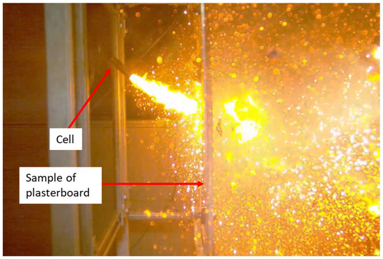
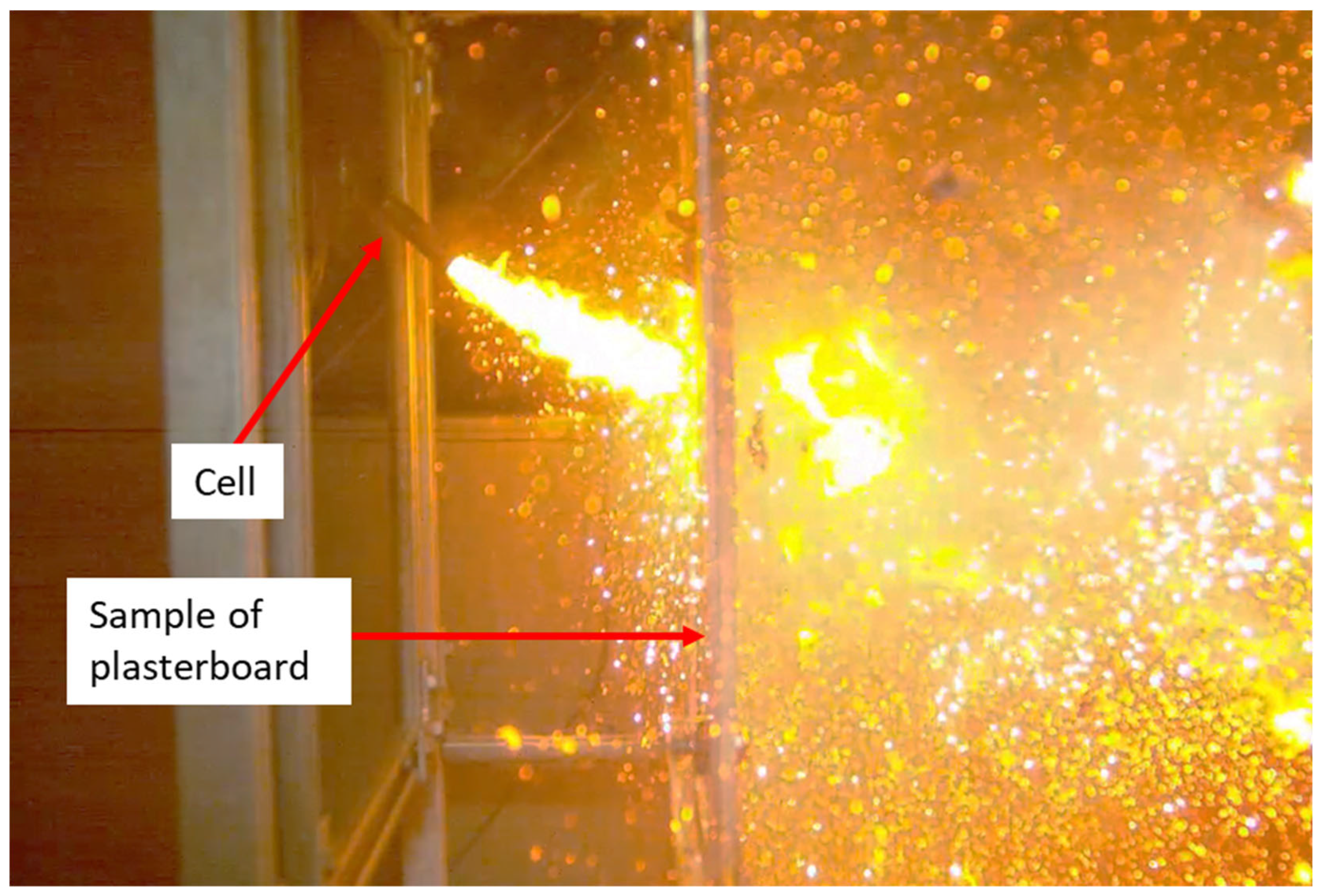
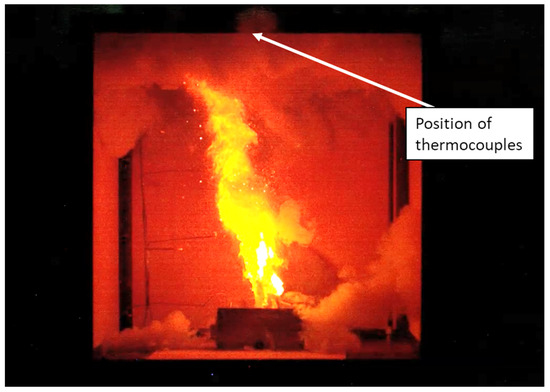
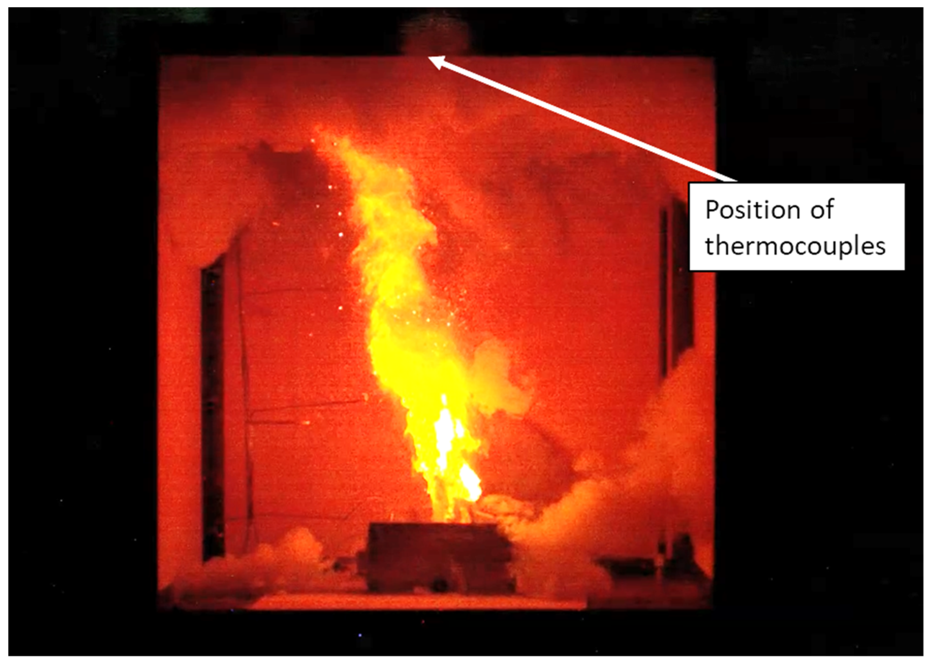
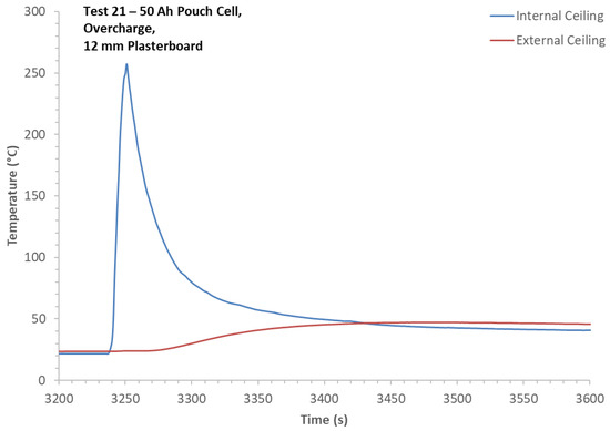
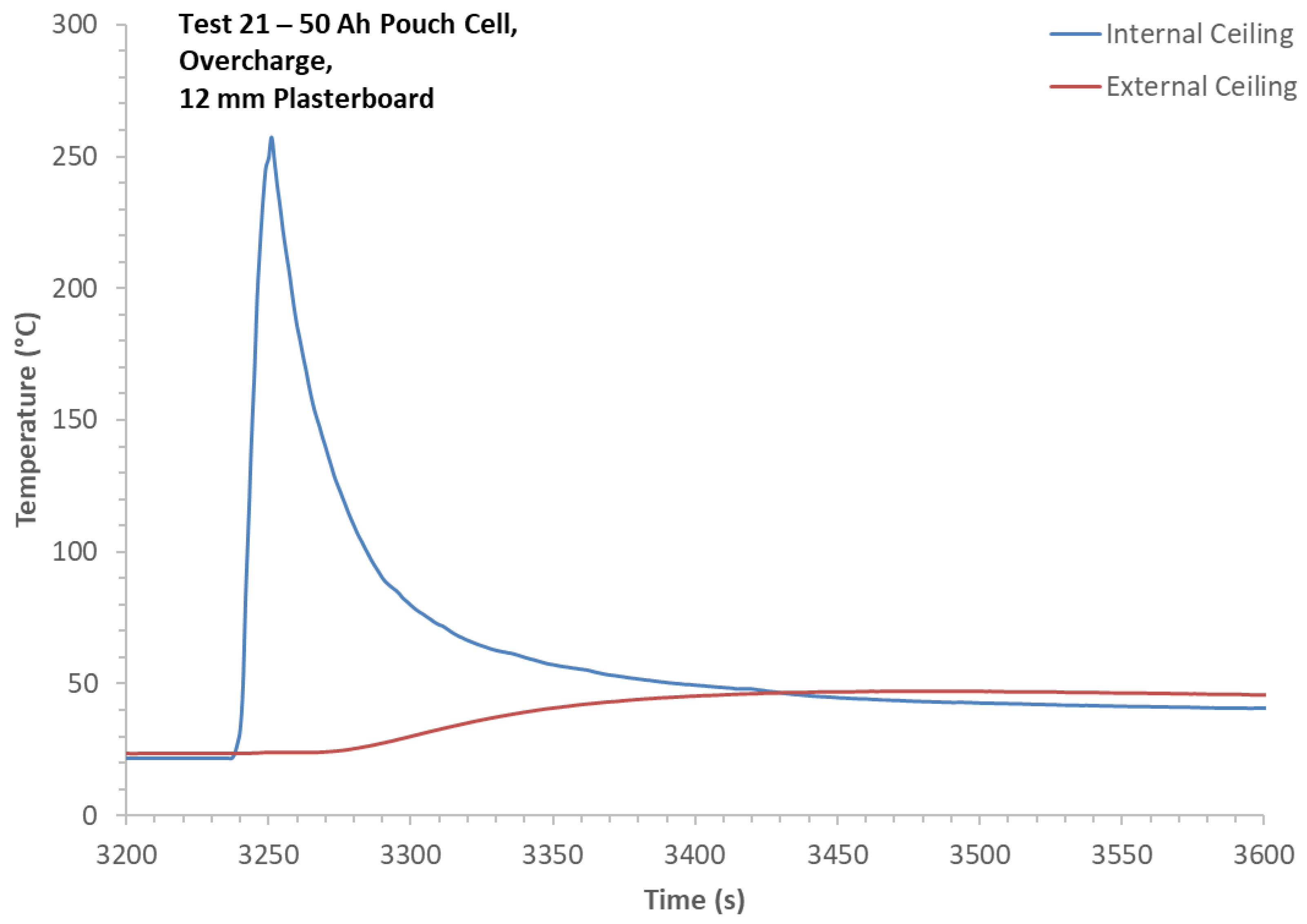
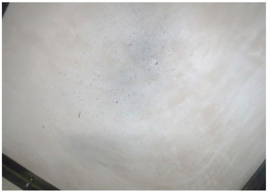
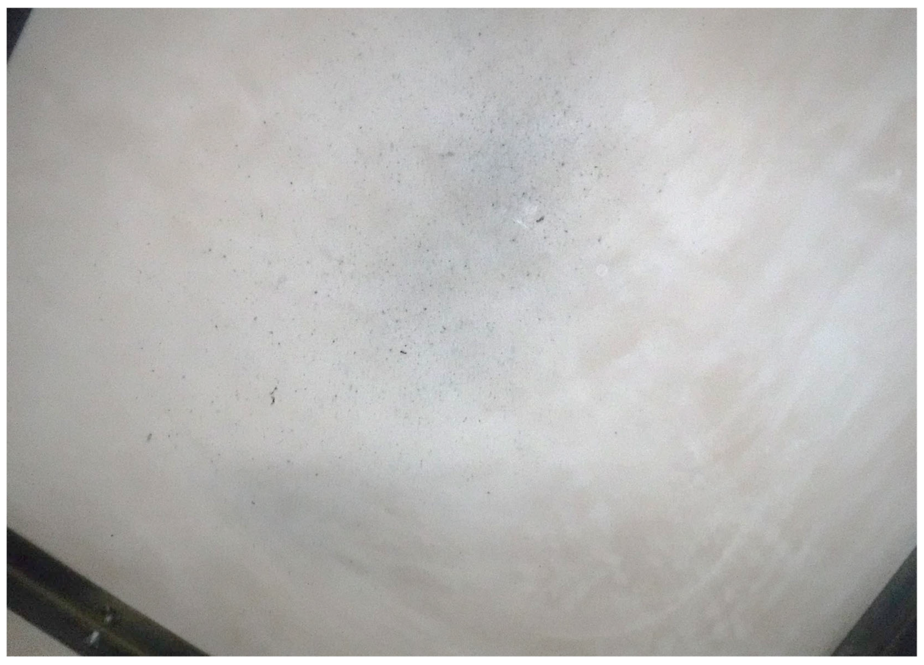
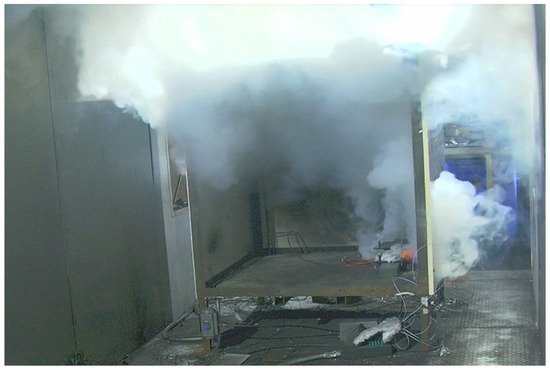
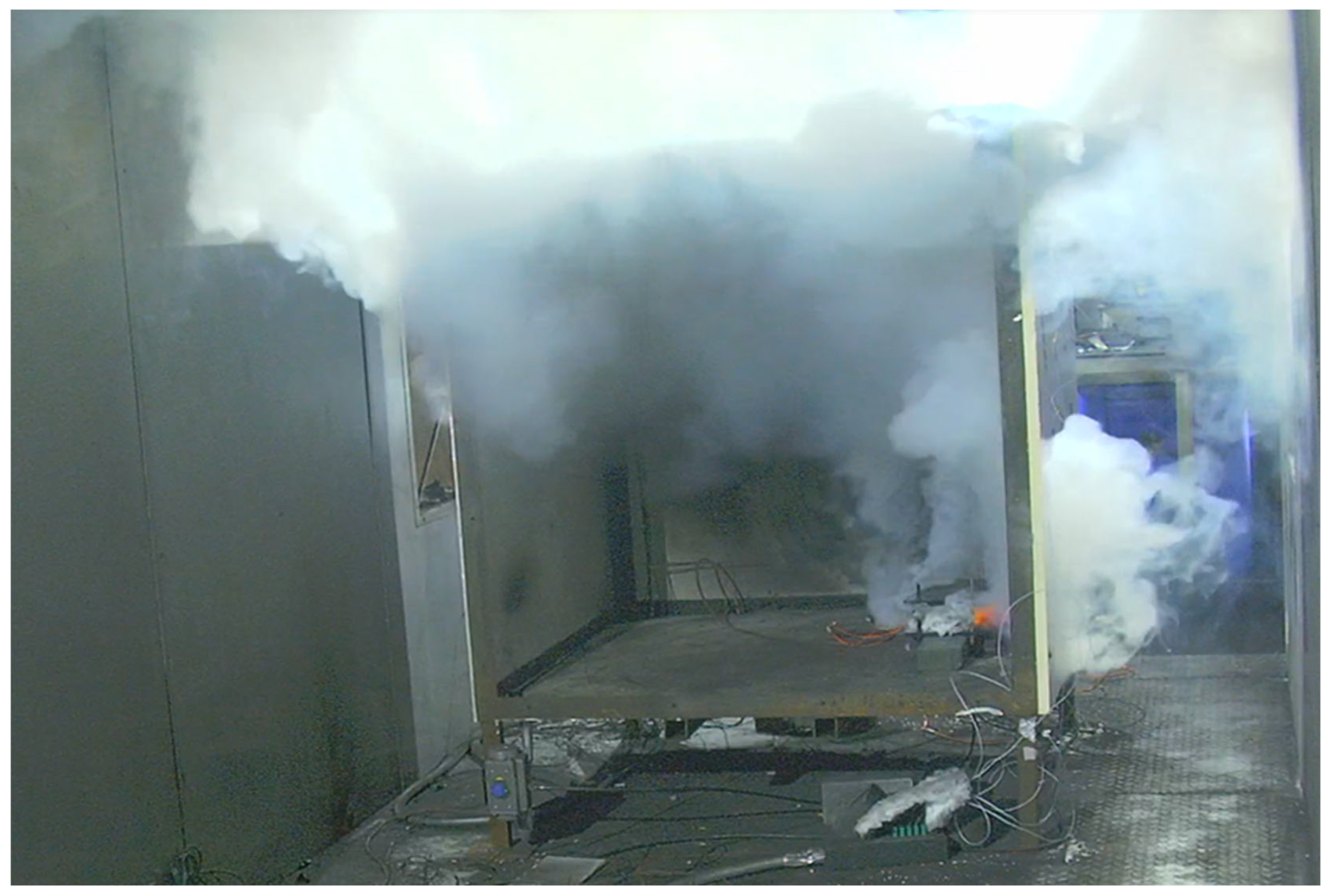
The purpose of these experiments was to understand how the building material reacted to direct flame impingement from a battery. These specific pouch cells were chosen because they generally self-ignite and produce a jet flame when they fail. For Test 21, the jet flame impinged on the ceiling (Figure 7) but lasted only 10 s. The jet’s centre did not impinge directly on the ceiling thermocouple; it impinged just to the side. The temperature rise on the back of the plasterboard ceiling was limited to below 50 °C (Figure 8). With Test 28, the cell’s jet fire impinged on the plasterboard wall. In both tests, the plasterboard was lightly stained with soot and burned particles originating from the battery, but not structurally damaged (Figure 9); therefore, in these tests, the plasterboard could withstand the short duration of the pouch cell fire without structural damage. However, it should be noted that these tests were just single cells and in instances of multiple cell battery packs, the jet fire could be sustained for longer or there could be multiple periods of jet fires as the pack burns.
Figure 7.
Test 21—jet fire during cell failure.
Figure 8.
Test 21—ceiling temperatures.
Figure 9.
Test 21—internal ceiling after test, showing some light staining with soot and particles.
3.4.2. Prismatic Cell Experiments (Tests 29 and 30)
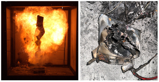
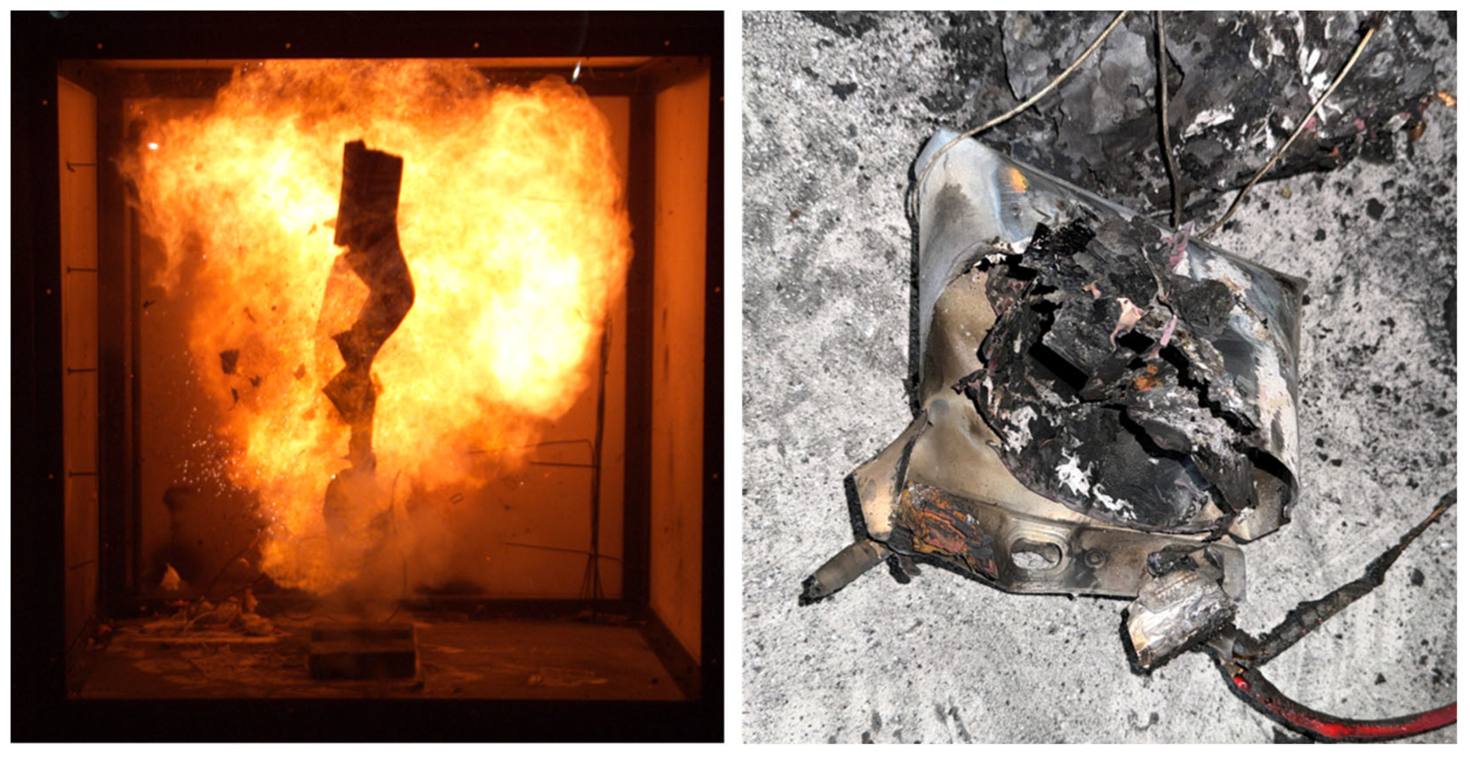
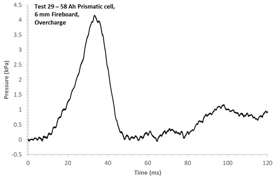
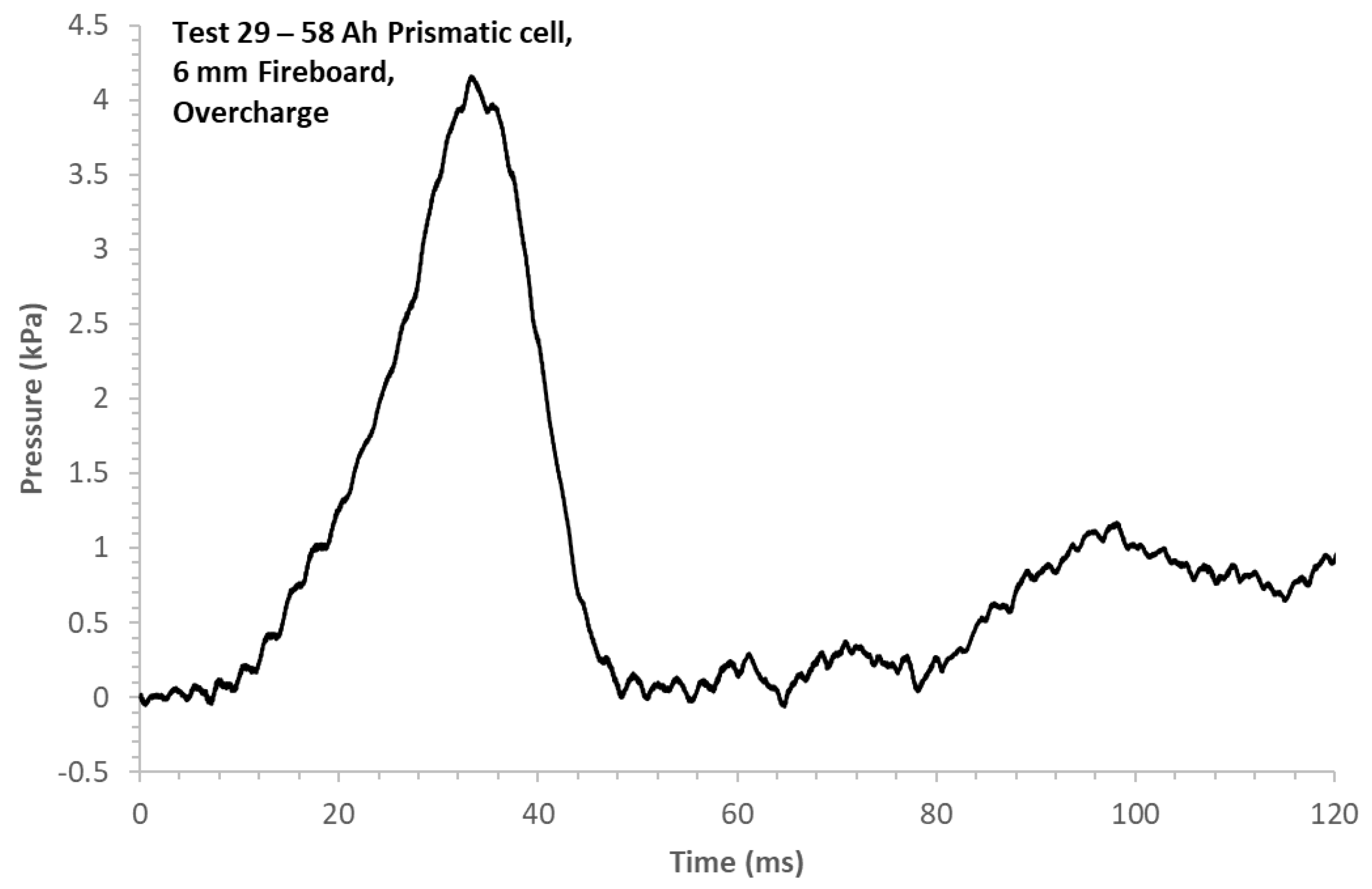
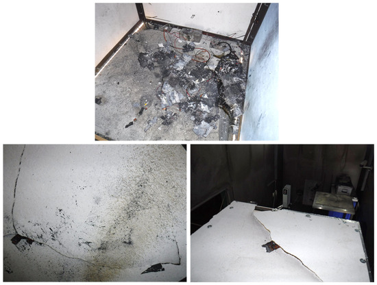
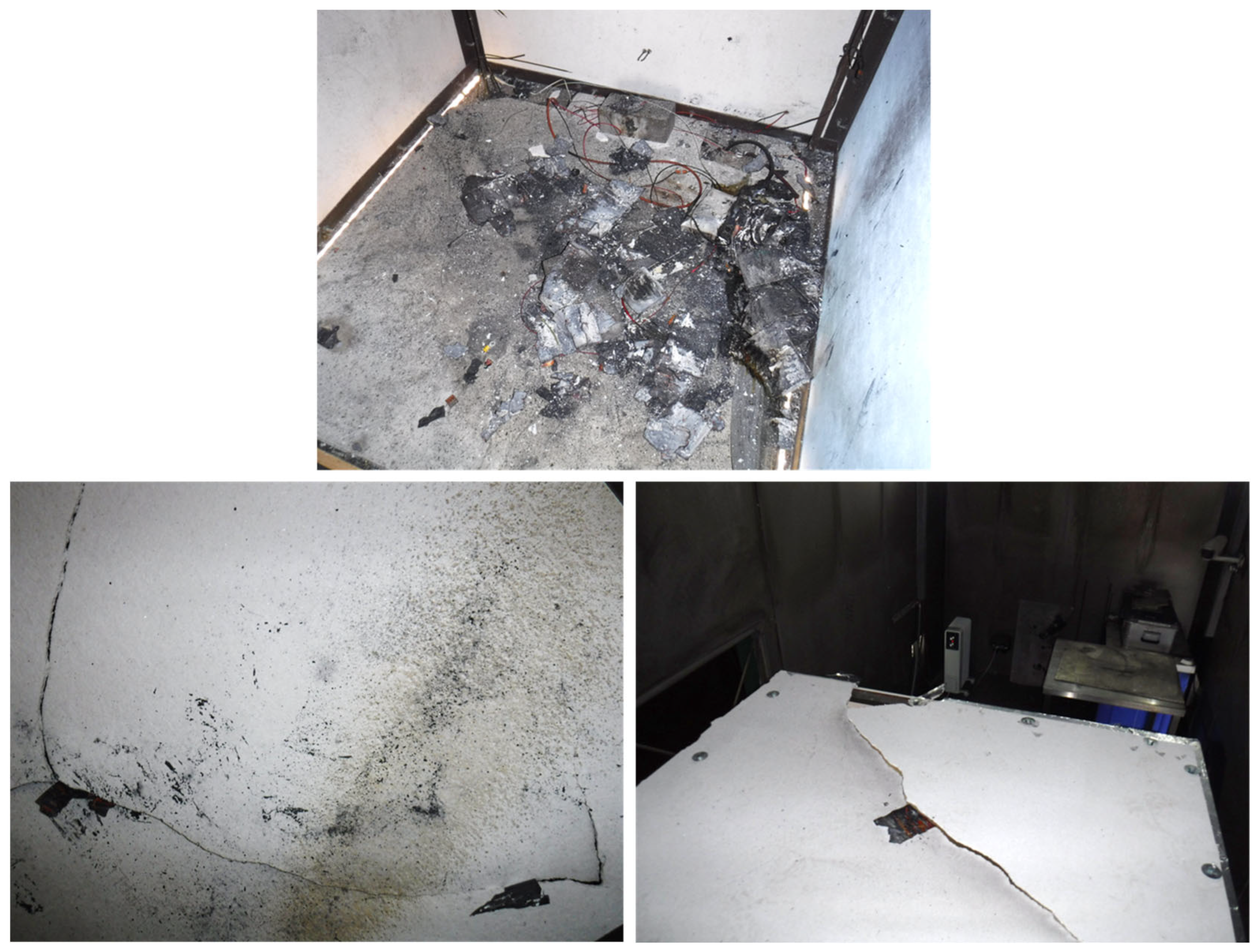
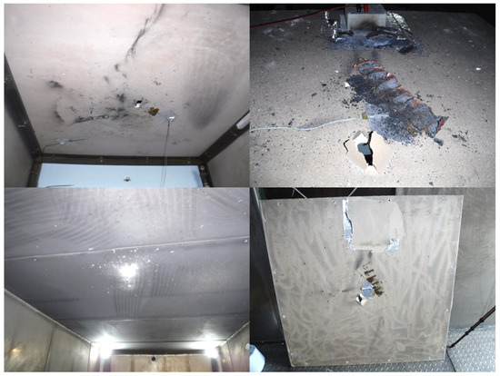
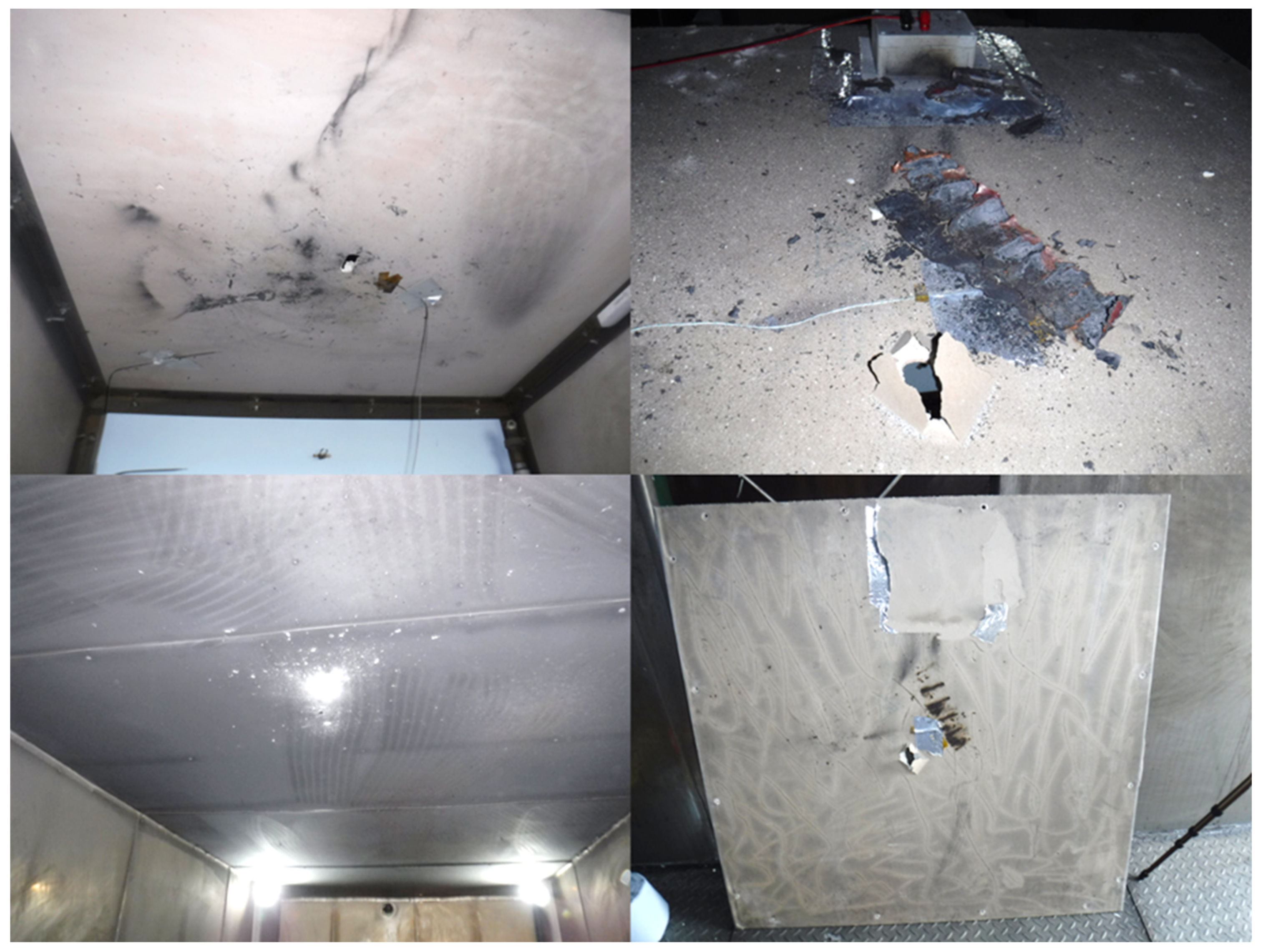
The purpose of Test 29 was to understand how the prismatic cells failed during overcharge and to assess their suitability for the experimental programme. This is why the cube was clad with 6 mm calcium silicate fireboard, and clear plastic sheeting was used to cover the viewing window rather than polycarbonate. However, the results of the experiment meant it was worth reporting. The cell has a safety vent that burst during overcharge, but as the thermal runaway continued, the cell failed catastrophically. The pressure inside the cell tore the top of the cell off, and most of the content was ejected and burned rapidly in what could be considered a deflagration (Figure 10). The clear plastic sheeting is expected to burst at around 1–2 kPa; the vent area left by the bursting of the sheet is 1.2 m2, the same as the length of the rig, which would lead to very effective explosion venting [35,36]. However, the peak pressure recorded by the internal pressure transducer was 4.2 kPa; the pressure rise to the peak occurred in just 26 ms (Figure 11). The damage caused by the event was confined to the cube’s ceiling; the fireboard was cracked open, and part of the jelly roll had been forced through the crack (Figure 12). The pressure of the event also caused the blast panels on the outer test chamber to burst; these are designed to burst at 1–2 kPa. The damage to the ceiling and the rate of pressure rise indicates that there could be some pressure effect due to the bursting-type failure mechanism of the cell, in addition to the rapid combustion of the flammable material within it.
Figure 10.
Prismatic cell during and after failure.
Figure 11.
Test 29—pressure trace.
Figure 12.
Test 29—rig after test; (top) cell aftermath, (left) internal cracked ceiling, (right) external cracked ceiling with jelly roll in crack.
Calcium silicate fireboard is often used in areas where more advanced fire protection than plasterboard is required. In this experiment, the fireboard was fixed to the edge of the cube frame, giving it an unsupported span of 1.1 m. The fireboard will likely be fixed to a carcass with supports around every 0.4 m in real-world applications. Cracking fireboard supported at intervals rather than just at the edges will potentially require more force.
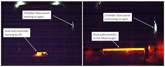
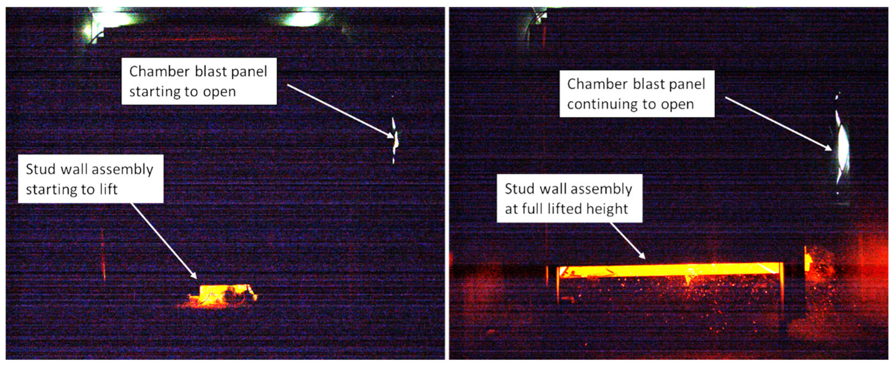
In Test 30, the cube rig was enclosed with a stud wall assembly of 75 mm × 50 mm timber members with 12 mm plasterboard on the inner face. The assembly covered the four side walls and the ceiling; the individual walls were attached with steel brackets and wooden blocks screwed into the wood carcass. The assembly was not connected to the rig as it was self-supporting, and it was felt the assembly had sufficient mass to form confinement; the assembly was >220 kg. When the cell failed, the stud wall assembly was lifted by the force of the event approximately 60–80 mm off the ground (Figure 13). This will have increased the enclosure’s volume and provided a vent for pressure relief. The maximum peak overpressure recorded by the internal pressure transducer was 3.8 kPa. In addition to lifting the assembly, the overpressure also pushed the walls apart at some of the joints; however, the plasterboard surfaces were not damaged or cracked. Again, the event caused the outer test chamber’s blast pane to burst as designed.
Figure 13.
Test 30—stills from video showing assembly starting to lift and at full height.
The pressure development in the small-scale room will be different to a standard room; however, the test chamber the room is situated in has a volume of around 44 m3. The overpressure within the test chamber, outside of the small-scale room, was sufficient to cause the chamber’s pressure relief panel to burst, but without further pressure measurements it is not possible to infer how the pressure developed in the larger volume.
3.4.3. Cylindrical Cell Block and Plasterboard Experiments (Tests 22–27, and 31)
These tests were designed to investigate if cells in a block can cause damage to the plasterboard walls, affect the fire resistance, or transfer a fire to a different room than the original battery failure. The purpose of the cell block was to give the opportunity for multiple cells to act as projectiles during the battery fire. In Test 24, with a seven-cell block of B cells, one cell punched a hole through the ceiling plasterboard, hit the outer test chamber roof with enough force to make a mark and deposit material on the stainless-steel surface (Figure 14). The contents of the cell fell back onto the rig and landed with enough residual heat to leave scorch marks on the paper surface of the plasterboard.
Figure 14.
Test 24—impact damage to ceiling of rig, roof of chamber and top of ceiling with cell contents in place and after removal of debris.
The only other test in which a cell penetrated the wall was Test 27. In this test, the cell hit the side wall lengthways, penetrated the skimmed plasterboard, landed on the chamber’s floor, and continued to burn for around 4 s. Cells also hit the walls in other tests, resulting in no apparent or minimal damage, such as chipped finishing plaster.
Not all the cells failed in the experiments with the cell blocks. Often, the cell block was disassembled during the event, and cells were projected around the rig; some cells were found to be still live, although they had been subjected to abnormal heat. In this sense, the experiment was not fully representative of blocks of cells from battery packs such as those from e-bikes/scooters. In these packs the cells are likely to be welded to bus bars, with cells electrically connected and contained within an outer case; however, it could be expected that pack disassembly is still a possibility if sufficient forces are generated.
3.4.4. Polyisocyanurate (PIR) Foam Experiments (Tests 32 and 33)
Two experiments were conducted with PIR foam; this foam is not generally used as a fire protection system but can form part of the building envelope. It burns in the presence of a flame, but on an open face, the foam extinguishes when the flame is removed; however, if a burning droplet is applied, the foam can burn with a sustained flame [37]. Also, when there is a channel and flame involved, radiative feedback can lead to sustained combustion of the foam [38]. The experiments aimed to understand if there was anything specific about a battery fire that could affect the behaviour of PIR foam.
In Test 32, the pouch cell block was positioned so the flame would impinge on the foam; whilst the battery flame was impinging on the foam, the foam could also be seen to burn, producing yellow smoke (Figure 15). Most of the smoke escaped through the top of the open front of the rig and a small proportion of this smoke escaped out of the slight gap between the frame of the rig and the bottom of the foam panel. Once the battery had finished burning, the foam could be seen to no longer be burning.
Figure 15.
Test 32—stills from video showing fire impinging wall and the smoke coming from the front of the rig and the bottom of the foam panel.
In Test 33, with the cylindrical seven-cell blocks, a cell was projected from the block; it hit the ceiling and passed through the foam. The cell landed on top of the cube and continued to burn with a flame for 24 s; the hole the cell made was seen to flame for 49 s (Figure 16). Cells, once projected, typically would burn for a few seconds. Therefore, the flames were likely the result of the foam burning, too. It is possible the hole left by the cell provided a means for radiative feedback to sustain the flaming combustion of the foam around the inside edge of the hole until the hole size increased and the feedback reduced enough that the flame could not be sustained.
Figure 16.
Test 33—hole and fire damage to ceiling panel; (left) internal, (right) external.
Using the high-speed video footage, the speed of the cell that penetrated the foam was calculated to be approximately 70 m/s (250 km/h) over its first 1.2 m of travel.
4. Conclusions
This preliminary research was designed to understand how building materials such as plasterboard, used as standard fire protection systems in buildings, are impacted by the fire dynamics of some types of battery fires, and highlight areas that may require further research. The experiments were not designed to replicate specific real-world scenarios such as an e-bike battery fire or a battery energy storage fire.
The results show that due to the dynamics of battery failure, cylindrical cells can travel significant distances at high speeds; the cells may also land while still on fire. The force which produces the cell movement is generated due to either material being rapidly vented, over a period of a few seconds, from the cell’s positive terminal, or most of the cell’s contents being ejected at once through the detached cell end cap. These mechanisms mean that the potential for flight, direction and speed appears to be stochastic; during flight direction and speed can also change.
Tests were undertaken at shorter distances, up to 1.2 m with the cells aimed at a target. The results show that cells can strike a surface with sufficient force to break through plasterboard skimmed with finishing plaster. A cylindrical cell also penetrated and passed through the PIR foam, leaving a hole that burned with flame for 25 s after the cell had extinguished; this is potentially due to the hole being small enough to allow for the chimney effect and radiative feedback mechanisms that would allow a sustained flame in the foam. Due to the stochastic nature of the cells’ flight, the hit rate on the targets was low; therefore, greater distances were not tested.
Pouch cells do not, as a rule, have an engineered vent and as the gas evolution caused by the thermal runaway exceeds the capacity of the cell’s soft casing, it tends to rupture. As the cells under test were clamped to mimic the confinement in a module or pack, the cells ruptured along the shortest edge. When the gas venting from the rupture ignited, it produced a jet flame for part of the duration; none of the experiments resulted in damage to the plasterboard or excessive heat transfer through it. Note that the largest pouch cell tested was a 50 Ah cell. A PIR foam test was conducted with pouch cells; the foam burned when the flame impinged, but the flaming stopped when the battery fire no longer impinged on the foam.
Prismatic cells have an engineered vent to release internal pressure. The prismatic cells tested burst and ejected all their contents, which burned rapidly, potentially resembling a deflagration. This indicated that the engineered vent was insufficient for the quantity of gas produced over the duration of the thermal runaway process. The overpressure produced by the cell failure in the rig was significant at 4.2 kPa and 3.8 kPa for the two experiments. The rate of pressure rise indicates that the bursting mechanism of the cell contributed to the overpressure. In both experiments, the force of the peak overpressure was sufficient to affect the fire envelope that would have been provided by the building material attached to the rig. The 6 mm calcium silicate fireboard on the ceiling was cracked open by the overpressure, and parts of the jelly roll passed through the cracks. The stud wall assembly was lifted, and the joints pushed apart; in real-world application, the room is likely to be larger in volume and stud wall is likely to be larger in surface area and be attached to a building. However, the overpressure impacted the larger test chamber with its 44 m3 volume, so it can still be expected that the pressure will still act on the walls to some degree, and further work measuring the pressure at different points is required to understand the implications of this. Furthermore, although the cell is 58 Ah, there are significantly larger prismatic cells on the market, and it is likely that a battery will consist of more than one cell.
The experiments demonstrate that, in the scenarios tested, the short duration battery fires did not cause thermal damage to the plasterboard and calcium silicate board tested. However, mechanical damage was caused due to the dynamic nature of the battery failure mechanisms. In a real-world scenario this type of damage could potentially affect the integrity of a fire protection envelope that was made from plasterboard or calcium silicate board.
Many types of building materials are tested using traditional fire testing standards, which use a standard fire profile derived from years of research. This allows a sample under test to be exposed to fire or heat level that is consistent, no matter where it is tested if the specific standard is being followed. For example, some furnace tests follow a standard cellulose fire curve [23,24,25] or ISO 22899 standard which is a jet fire generated by a jet of propane with a set flow rate that can cause mechanical damage through momentum-based erosion [26,27].
There are no current set standard battery fires; researchers have explored the heat release rates based on the energy stored in cells, through methods such as accelerated rate calorimetry [39] or small-scale open field experiments [40]. Although this study is limited in nature due to many of the experiments being with single cells or with cells unconfined by pack casing, the results demonstrate the potential for variability in cell failure outcomes based on chemistry, format and sizes. This demonstrates that battery fires are not just defined by the amount or rate of heat released; there is the dynamic nature of the failure to consider. This highlights that considerable work and a certain degree of novel thinking will be needed to design standard battery fires, and each one will need to be specific to the type of battery it is designed to emulate. Standard test methods designed to subject articles to the rigours of battery fires already exist for battery storage cabinets [41] and transportation packaging [42]. However, these tests use lithium cells in a worst-case scenario for state of charge and quantity for the application of the test subject. Using cells for testing is expensive, a waste of a finite resource and leaves residual hazards for the test house to deal with. A test for mass market products such as building materials would need to be a different fuel, such as gas, for safety and sustainability reasons.
As previously mentioned, some of the limiting factors to this study are that the cells used are not enclosed in packs and, except for the cylindrical cell cluster experiments, the samples were all single cells. In addition to the question of if a battery consisting of multiple cells will burn with more intensity than a single cell, burn for longer or a combination, there is also the fire load of any battery pack casing, wiring and circuitry to consider. This further highlights the considerations that need to be made if a standard battery fire was to be designed.
4.1. Summary of Key Findings
- The short duration of the battery fires in these tests did not cause heat damage to plasterboard or calcium silicate fireboard; however, it should be noted these were single-cell tests.
- Cylindrical cells tested were able to travel at high speed for several metres during failure and in experiments over distances up to 1.2 m had enough force to pierce plasterboard. This demonstrates that cells present an ignition risk remote from the source of a battery fire.
- Prismatic cells tested failed with a significant pressure event that was capable of mechanically disrupting stud walls on the small-scale room rig and mechanically damaging calcium silicate boards. The overpressure also caused the pressure relief panel to burst in the test chamber.
4.2. Recommendation for Future Work
- More work is required to understand the impact that the failure of large-format nickel-based prismatic cells can have on the structural integrity of building fire envelopes, from the point of view of overpressure, with consideration for multiple cell-failure events.
- More work is required to understand the hazards of projectile cells during different battery fires, their impact on structures, and the spread of fire away from the point of origin.
- Detailed further experimental work is required to understand how real-world battery fire dynamics differ to standard fire tests.
- Further work is needed to explore methods of recreating battery fires, for the purposes of standard testing, with the use of safer and more sustainable fuels.
Author Contributions
J.G.: Conceptualization, Methodology, Investigation, Funding Acquisition, Writing—original draft. J.E.H.B.: Conceptualization, Funding Acquisition, Supervision, Writing—review and editing. G.E.H.: Investigation. S.L.G.: Investigation. P.A.P.R.: Investigation. J.W.M.: investigation. All authors have read and agreed to the published version of the manuscript.
Funding
This research received no external funding. The work detailed in this article was internally funded by the United Kingdom Health and Safety Executive (HSE). The contents of this article, including any opinions and/or conclusions expressed are entirely those of the authors and do not necessarily reflect HSE policy.
Data Availability Statement
All relevant data discussed have been reported in the main body of this paper and any methods for calculations cited accordingly.
Conflicts of Interest
The authors declare no conflicts of interest.
References
- Nordelöf, A.; Messagie, M.; Tillman, A.-M.; Söderman, M.L.; Van Mierlo, J. Environmental impacts of hybrid, plug-in hybrid, and battery electric vehicles—What can we learn from life cycle assessment? Int. J. Life Cycle Assess. 2014, 19, 1866–1890. [Google Scholar] [CrossRef] [Scilit]
- Liu, Y.; Zhang, R.; Wang, J.; Wang, Y. Current and future lithium-ion battery manufacturing. iScience 2021, 24, 102332. [Google Scholar] [CrossRef] [Scilit]
- Berg, P.; Soellner, J.; Herrmann, M.; Jossen, A. Structural dynamics of lithium-ion cells—Part II: Investigation of large-format prismatic cells and method evaluation. J. Energy Storage 2020, 28, 101246. [Google Scholar] [CrossRef] [Scilit]
- Bridgewater, G.; Capener, M.J.; Brandon, J.; Lain, M.J.; Copley, M.; Kendrick, E. A Comparison of Lithium-Ion Cell Performance across Three Different Cell Formats. Batteries 2021, 7, 38. [Google Scholar] [CrossRef] [Scilit]
- Mao, Y.-Q.; Dong, G.-H.; Fu, Y.-T.; Li, Y.-Q.; Huang, P.; Fu, S.-Y. High performance shape-adjustable structural lithium-ion battery based on hybrid fiber reinforced epoxy composite. Compos. Struct. 2023, 325, 117598. [Google Scholar] [CrossRef] [Scilit]
- Chen, Y.; Kang, Y.; Zhao, Y.; Wang, L.; Liu, J.; Li, Y.; Liang, Z.; He, X.; Li, X.; Tavajohi, N.; et al. A review of lithium-ion battery safety concerns: The issues, strategies, and testing standards. J. Energy Chem. 2021, 59, 83–99. [Google Scholar] [CrossRef] [Scilit]
- Feng, X.; Ouyang, M.; Liu, X.; Lu, L.; Xia, Y.; He, X. Thermal runaway mechanism of lithium ion battery for electric vehicles: A review. Energy Storage Mater. 2018, 10, 246–267. [Google Scholar] [CrossRef] [Scilit]
- Jindal, P.; Bhattacharya, J. Review—Understanding the Thermal Runaway Behavior of Li-Ion Batteries through Experimental Techniques. J. Electrochem. Soc. 2019, 166, A2165. [Google Scholar] [CrossRef] [Scilit]
- Ouyang, D.; Chen, M.; Huang, Q.; Weng, J.; Wang, Z.; Wang, J. A Review on the Thermal Hazards of the Lithium-Ion Battery and the Corresponding Countermeasures. Appl. Sci. 2019, 9, 2483. [Google Scholar] [CrossRef] [Scilit]
- Peng, R.; Kong, D.; Ping, P.; Wang, G.; Gao, X.; Lv, H.; Zhao, H.; He, X.; Zhang, Y.; Dai, X. Thermal runaway modeling of lithium-ion batteries at different scales: Recent advances and perspectives. Energy Storage Mater. 2024, 69, 103417. [Google Scholar] [CrossRef] [Scilit]
- Şen, M.; Özcan, M.; Eker, Y.R. A review on the lithium-ion battery problems used in electric vehicles. Next Sustain. 2024, 3, 100036. [Google Scholar] [CrossRef] [Scilit]
- Shen, R.; Quan, Y.; McIntosh, J.D.; Salem, A.; Wang, Q. Fire Safety of Battery Electric Vehicles: Hazard Identification, Detection, and Mitigation. SAE Int. J. Electrified Veh. 2024, 13, 279–294. [Google Scholar] [CrossRef] [Scilit]
- Wang, Q.; Mao, B.; Stoliarov, S.I.; Sun, J. A review of lithium ion battery failure mechanisms and fire prevention strategies. Prog. Energy Combust. Sci. 2019, 73, 95–131. [Google Scholar] [CrossRef] [Scilit]
- Jia, Z.; Min, Y.; Qin, P.; Mei, W.; Meng, X.; Jin, K.; Sun, J.; Wang, Q. Effect of safety valve types on the gas venting behavior and thermal runaway hazard severity of large-format prismatic lithium iron phosphate batteries. J. Energy Chem. 2024, 89, 195–207. [Google Scholar] [CrossRef] [Scilit]
- Jia, Z.; Wang, S.; Qin, P.; Li, C.; Song, L.; Cheng, Z.; Jin, K.; Sun, J.; Wang, Q. Comparative investigation of the thermal runaway and gas venting behaviors of large-format LiFePO4 batteries caused by overcharging and overheating. J. Energy Storage 2023, 61, 106791. [Google Scholar] [CrossRef] [Scilit]
- DiNenno, P.J.; Drysdale, D.; Beyler, C.L.; Walton, W.D.; Custer, R.L.P.; Hall, J.R., Jr.; Watts, J.M., Jr. SFPE Handbook for Fire Protection Engineering; NFPA: Quincy, MA, USA, 2002. [Google Scholar]
- Chen, H.; Buston, J.E.H.; Gill, J.; Howard, D.; Williams, R.C.E.; Read, E.; Abaza, A.; Cooper, B.; Wen, J.X. A simplified mathematical model for heating-induced thermal runaway of lithium-ion batteries. J. Electrochem. Soc. 2021, 168, 010502. [Google Scholar] [CrossRef] [Scilit]
- Huang, Z.; Li, X.; Wang, Q.; Duan, Q.; Li, Y.; Li, L.; Wang, Q. Experimental investigation on thermal runaway propagation of large format lithium ion battery modules with two cathodes. Int. J. Heat. Mass. Transf. 2021, 172, 121077. [Google Scholar] [CrossRef] [Scilit]
- Vendra, C.M.R.; Shelke, A.V.; Buston, J.E.; Gill, J.; Howard, D.; Read, E.; Abaza, A.; Cooper, B.; Wen, J.X. Numerical and experimental characterisation of high energy density 21700 lithium-ion battery fires. Process Saf. Environ. Prot. 2022, 160, 153–165. [Google Scholar] [CrossRef] [Scilit]
- Sanfeliu Meliá, C.; Meraner, C.; Steen-Hansen, A.; Olsø, B.G. Full-scale room fire of Li-ion battery modules undergoing thermal runaway. Fire Saf. J. 2026, 161, 104680. [Google Scholar] [CrossRef] [Scilit]
- Abbott, K.C.; Buston, J.E.; Gill, J.; Goddard, S.L.; Howard, D.; Howard, G.E.; Read, E.; Williams, R.C. Experimental study of three commercially available 18650 lithium ion batteries using multiple abuse methods. J. Energy Storage 2023, 65, 107293. [Google Scholar] [CrossRef] [Scilit]
- Hadjisophocleous, G.V.; Benichou, N. Performance criteria used in fire safety design. Autom. Constr. 1999, 8, 489–501. [Google Scholar] [CrossRef] [Scilit]
- BS EN 1364-1:2015; Fire Resistance Tests for Non-Loadbearing Elements—Walls. BSI: London, UK, 2015. Available online: https://knowledge.bsigroup.com/products/fire-resistance-tests-for-non-loadbearing-elements-walls?version=tracked (accessed on 16 November 2025).
- BS 476-20:1987; Fire Tests on Building Materials and Structures—Method for Determination of the Fire Resistance of Elements of Construction (General Principles). BSI: London, UK, 1987. Available online: https://knowledge.bsigroup.com/products/fire-tests-on-building-materials-and-structures-method-for-determination-of-the-fire-resistance-of-elements-of-construction-general-principles?version=standard (accessed on 16 October 2025).
- BS EN 13501-1:2018; Fire Classification of Construction Products and Building Elements—Classification Using Data from Reaction to Fire Tests. BSI: London, UK, 2018. Available online: https://knowledge.bsigroup.com/products/fire-classification-of-construction-products-and-building-elements-classification-using-data-from-reaction-to-fire-tests?version=tracked (accessed on 16 October 2025).
- Boaler, G.; Crewe, R.; Cronin, P.M.; Russo, S.; Thurlbeck, S.; Yuan, J. General Guidance on Testing, Assessment and Certification of PFP—Part 1; PFPNet: Macclesfield, UK, 2020; Available online: https://www.icorr.org/wp-content/uploads/2020/07/PFPNet-TAC-Guidance-Document-PFPNet2020-002-Issue-1.pdf (accessed on 20 October 2025).
- BS ISO 22899-1:2021; Determination of the Resistance to Jet Fires of Passive Fire Protection Materials—General Requirements. BSI: London, UK, 2021.
- Chen, Y.; Punati, N.; Ray, S.S.; Yang, L.; Prasad, K. Thermal failure time of non-loadbearing gypsum board assemblies in standard furnace tests. Appl. Therm. Eng. 2017, 127, 1285–1292. [Google Scholar] [CrossRef] [Scilit]
- Kolaitis, D.I.; Asimakopoulou, E.K.; Founti, M.A. Fire behaviour of gypsum plasterboard wall assemblies: CFD simulation of a full-scale residential building. Case Stud. Fire Saf. 2017, 7, 23–35. [Google Scholar] [CrossRef] [Scilit]
- Weber, B. Heat transfer mechanisms and models for a gypsum board exposed to fire. Int. J. Heat Mass Transf. 2012, 55, 1661–1678. [Google Scholar] [CrossRef] [Scilit]
- Thi, V.D.; Khelifa, M.; Oudjene, M.; El Ganaoui, M.; Rogaume, Y. Numerical simulation of fire integrity resistance of full-scale gypsum-faced cross-laminated timber wall. Int. J. Therm. Sci. 2018, 132, 96–103. [Google Scholar] [CrossRef] [Scilit]
- Meng, Q.; Zhang, X.; Hao, H.; James, I.; Beel, M. An investigation of impact resistance capacity of polypropylene (PP) added plasterboard subjected to soft-body impact. Compos. Struct. 2021, 275, 114370. [Google Scholar] [CrossRef] [Scilit]
- Sauer, N.G.; Gaudet, B.; Barowy, A. Experimental investigation of explosion hazard from lithium-ion battery thermal runaway effluent gas. Fuel 2024, 378, 132818. [Google Scholar] [CrossRef] [Scilit]
- NFPA 80A:2022; Recommended Practice for Protection of Buildings from Exterior Fire Exposures. NFPA: Quincy, MA, USA, 2022.
- Fakandu, B.M.; Andrews, G.E.; Phylaktou, H.N. Vent burst pressure effects on vented gas explosion reduced pressure. J. Loss Prev. Process Ind. 2015, 36, 429–438. [Google Scholar] [CrossRef] [Scilit]
- Zhang, C.; Dong, H.; Shang, S.; Zhang, K.; Zhang, Z.; Gao, W. Investigation of the length-to-diameter ratio of ducts effect on the oscillation propagation behavior and vented characteristics for propane-air vented explosions. J. Loss Prev. Process Ind. 2023, 86, 105186. [Google Scholar] [CrossRef] [Scilit]
- McKenna, S.T.; Jones, N.; Peck, G.; Dickens, K.; Pawelec, W.; Oradei, S.; Harris, S.; Stec, A.A.; Hull, T.R. Fire behaviour of modern façade materials—Understanding the Grenfell Tower fire. J. Hazard. Mater. 2019, 368, 115–123. [Google Scholar] [CrossRef] [Scilit]
- Mendez, J.E.; McLaggan, M.S.; Lange, D. Upward flame spread behaviour of cladding materials on a medium-scale ventilated façade experimental setup with a single combustible wall. Fire Saf. J. 2024, 142, 104020. [Google Scholar] [CrossRef] [Scilit]
- Jin, C.; Xu, C.; Dong, W.; Huang, J.; Feng, X. Thermal runaway modeling and heat source quantification of Mn-based lithium-ion batteries via coupled kinetic and thermal analysis. J. Energy Storage 2026, 154, 121214. [Google Scholar] [CrossRef] [Scilit]
- Chen, H.; Buston, J.E.; Gill, J.; Howard, D.; Williams, R.C.; Vendra, C.M.R.; Shelke, A.; Wen, J.X. An experimental study on thermal runaway characteristics of lithium-ion batteries with high specific energy and prediction of heat release rate. J. Power Sources 2020, 472, 228585. [Google Scholar] [CrossRef] [Scilit]
- VDMA 24994; Extended Test Conditions for Battery Storage. VDMA: Frankfurt am Main, Germany, 2024. Available online: https://www.vdma.eu/en/viewer/-/v2article/render/126584547 (accessed on 21 April 2026).
- IATA. Battery Guidance Document—Transport of Lithium Metal, Lithium Ion and Sodium Ion Batteries; IATA: Montreal, QC, Canada, 2026; Available online: https://www.iata.org/contentassets/05e6d8742b0047259bf3a700bc9d42b9/lithium-battery-guidance-document.pdf?ref=athena-tactical-survival.ghost.io (accessed on 21 April 2026).

Disclaimer/Publisher’s Note: The statements, opinions and data contained in all publications are solely those of the individual author(s) and contributor(s) and not of MDPI and/or the editor(s). MDPI and/or the editor(s) disclaim responsibility for any injury to people or property resulting from any ideas, methods, instructions or products referred to in the content. |
© 2026 by the authors. Licensee MDPI, Basel, Switzerland. This article is an open access article distributed under the terms and conditions of the Creative Commons Attribution (CC BY) license.