


Abstract
L-shaped tunnels frequently occur in underground coal mines because of geological and operational limitations. Their complex geometry increases ventilation resistance and causes non-uniform airflow, promoting combustible gas accumulation and resulting in a greater fire risk than in straight tunnels. In this work, Fire Dynamics Simulator was employed to quantify the effects of the fire source’s transverse position, curvature radius, heat release rate, and imposed longitudinal ventilation on both the critical velocity and the extent of smoke back-layering. The analysis shows that higher heat-release rates elevate the critical velocity, whereas a centrally located fire yields the lowest value. Shifting the fire toward either sidewall or adopting a larger curvature radius results in a higher critical velocity. In addition, the extent of upstream smoke back-layering increases with curvature, peaking when the ignition point lies close to the convex sidewall. Specifically, with a ventilation velocity of 0.95 m/s and a centerline fire, the back-layering length extends from 23 m ( = 5 m) to 40 m ( = 10 m). Based on theoretical derivation and dimensional analysis, several dimensionless parameters were developed that incorporate both the transverse fire-source position and the curvature radius to modify the dimensionless heat-release rate. Finally, dimensionless predictive models for the critical velocity and back-layering length, incorporating the effects of the curvature radius and the fire transverse position, were developed. These models provide a theoretical foundation and practical framework for fire prevention and ventilation design in L-shaped tunnels.
1. Introduction
In recent years, continued economic growth and persistent energy demand have maintained coal as a key part of the energy structure, and coal production has remained at a high level [1]. Underground coal mines contain an extensive and complex network of roadways [2,3,4,5]. Constrained by geological conditions, coal seam distribution, and mining processes, these tunnels typically have narrow cross-sections and complicated alignments. Among them, L-shaped tunnels, characterized by sharp turns, are commonly found in connection roadways and panel layouts [6,7]. Such tunnel configurations not only increase local ventilation resistance and complicate airflow distribution but also significantly affect smoke propagation and accumulation during fires [8,9], posing distinctive challenges to mine safety. In high-gas mines, turning sections of L-shaped tunnels are prone to forming vortex zones and ventilation dead ends [10], which promote the accumulation of combustible gases and further elevate the risks of fires and explosions [11,12,13].
Mine fires have long been one of the most serious hazards in coal mine operations. Owing to their geometric complexity, L-shaped tunnels exhibit a higher probability of fire occurrence [14,15,16]. These tunnels are typically located in areas with dense equipment installations, such as conveyor transfer points and electrical or mechanical chambers, where ignition can be triggered by equipment aging, mechanical friction, or blasting operations. Moreover, non-uniform airflow distribution within the curved section leads to heat buildup, while limited heat dissipation further increases fire susceptibility. Once ignition occurs, the smoke behavior under longitudinal ventilation in L-shaped sections differs markedly from that in straight segments [17]. The curvature induces centrifugal effects that deflect smoke toward the outer wall; coupled with buoyancy and inertial forces, this interaction disrupts the stratified structure of smoke and alters its propagation path. Commonly observed phenomena include smoke accumulation near the outer wall and local backflow near the inner wall. This asymmetric flow field makes it more difficult to determine the critical velocity and the smoke back-layering length, and thus reduces the direct applicability of models originally established for straight tunnels.
A substantial body of research has examined smoke transport in tunnel fire scenarios. For instance, Liu et al. [18] investigated combustion characteristics in inclined tunnels through experiments and simulations, focusing on temperature, velocity, density, and pressure distributions. Yao et al. [19] investigated smoke movement and control in H-shaped tunnels, proposed a driving-force model for preventing backflow, and identified the critical ventilation velocity. Lin et al. [20] used full-scale measurements and numerical analysis in U-shaped tunnels to illustrate the role of longitudinal ventilation in shaping smoke accumulation patterns and diffusion behavior in single and linked tunnel segments. Using small-scale experiments together with simulation methods, Li et al. [21] examined how different fire source positions in excavation tunnels influence the resulting maximum temperature. Peng et al. [22] combined theoretical and numerical approaches to analyze smoke diffusion, temperature, and CO concentration, providing insights into smoke descent behavior and human exposure conditions. Most of these studies, however, have focused on fires occurring in straight tunnels or with fire sources positioned along the tunnel centerline. In practice, mine fire investigations indicate that ignition points frequently deviate from the tunnel axis and are often located near the concave or convex sidewalls of L-shaped bends, such as at tunnel intersections, equipment zones, or weakly supported areas [14]. These asymmetric fire source positions further alter smoke propagation and air-entrainment processes. On one hand, wall attachment reduces air entrainment, potentially leading to incomplete combustion and higher concentrations of toxic gases. On the other hand, lower airflow velocity near the wall promotes smoke accumulation in corners, creating high-temperature and high-density regions that hinder firefighting and rescue operations. Furthermore, the centrifugal forces acting on smoke differ when fires occur near the concave versus convex walls of an L-shaped tunnel, leading to distinct propagation and temperature patterns [23].
Despite progress in research, studies that systematically examine smoke back-layering and critical velocity while accounting for both near-wall ignition and the distinct geometry of L-shaped tunnels remain insufficient. In this study, numerical modeling and theoretical methods are employed to evaluate the influence of fire source lateral position, curvature radius, and longitudinal ventilation on the resulting back-layering length and critical velocity. The findings provide a theoretical basis and computational tools to support fire-control strategies, ventilation-system design, and emergency management in L-shaped mine tunnels.
2. Numerical Simulation Method
2.1. FDS Model
Numerical simulations were performed in this work using Fire Dynamics Simulator (FDS 6.7.1). FDS solves the Navier–Stokes equations using a Large Eddy Simulation formulation and is specifically designed to capture fire-driven thermal fluid processes. It has been extensively applied to simulate smoke movement, temperature distribution, and toxic gas transport in buildings and tunnels, and its reliability in tunnel fire research has been widely validated [24].
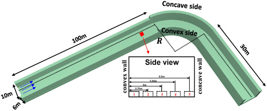
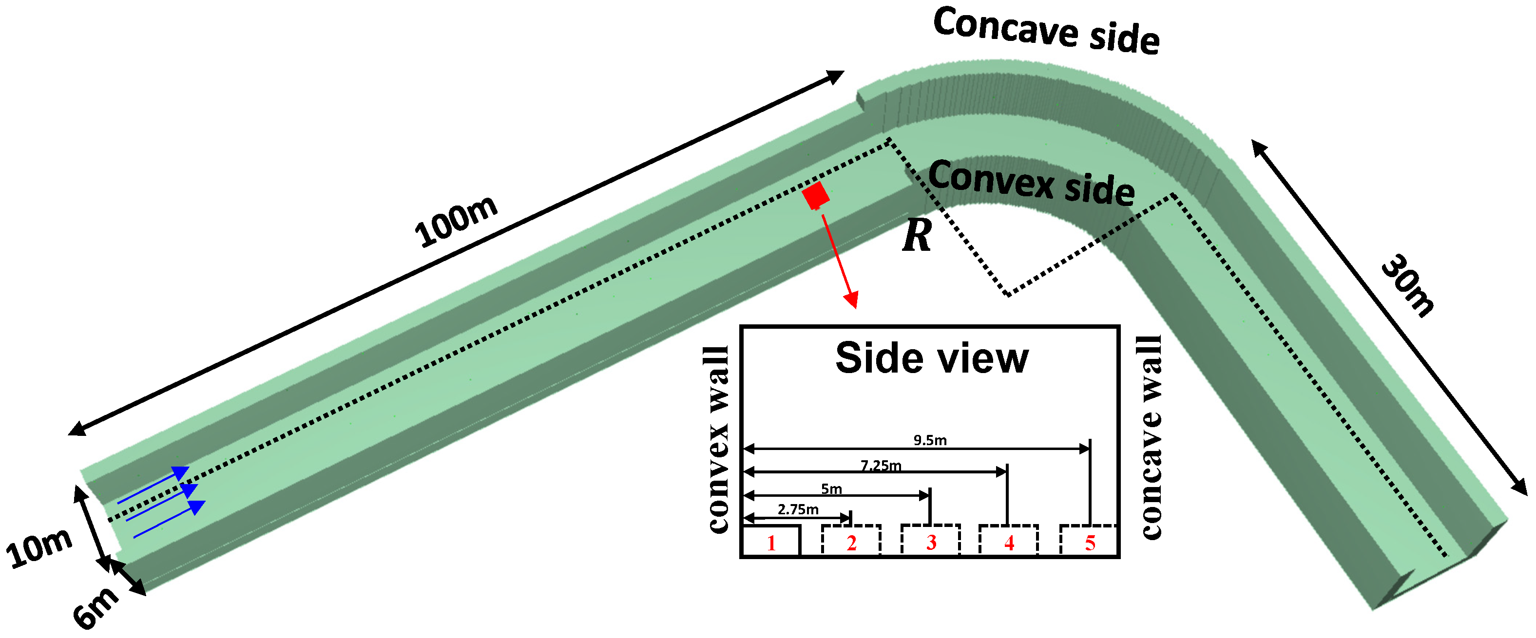
In FDS, several full-scale L-shaped tunnel models with different curvature radii were established, as illustrated in Figure 1. Each tunnel consisted of three sections: a 100 m straight inlet section, a curved section with a curvature radius , and a 30 m straight outlet section. The two sidewalls of the curved portion correspond to the concave and convex walls, respectively. The tunnel cross-section was 10 m (width) × 6 m (height). All solid boundaries (walls, floor, and ceiling) were specified as INERT. Longitudinal ventilation was imposed by applying a VENT at the left inlet. The fire source size was 1 m × 1 m × 0.5 m, and a constant heat release rate was prescribed. Fire-source transverse positions followed Figure 1, with the distance to the convex wall increased stepwise from 0.5 m to 9.5 m, representing five locations: adjacent/near the convex wall, centerline, and near/adjacent the concave wall. CO and soot yields adopted the default FDS combustion settings, and an ambient temperature of 25 °C was used.
Figure 1.
Tunnel established in numerical simulation (1, 2, 3, 4, 5 respectively represent the transverse positions of different fire sources).
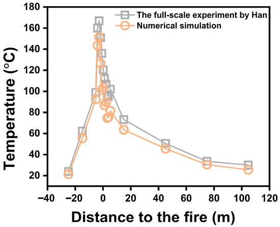
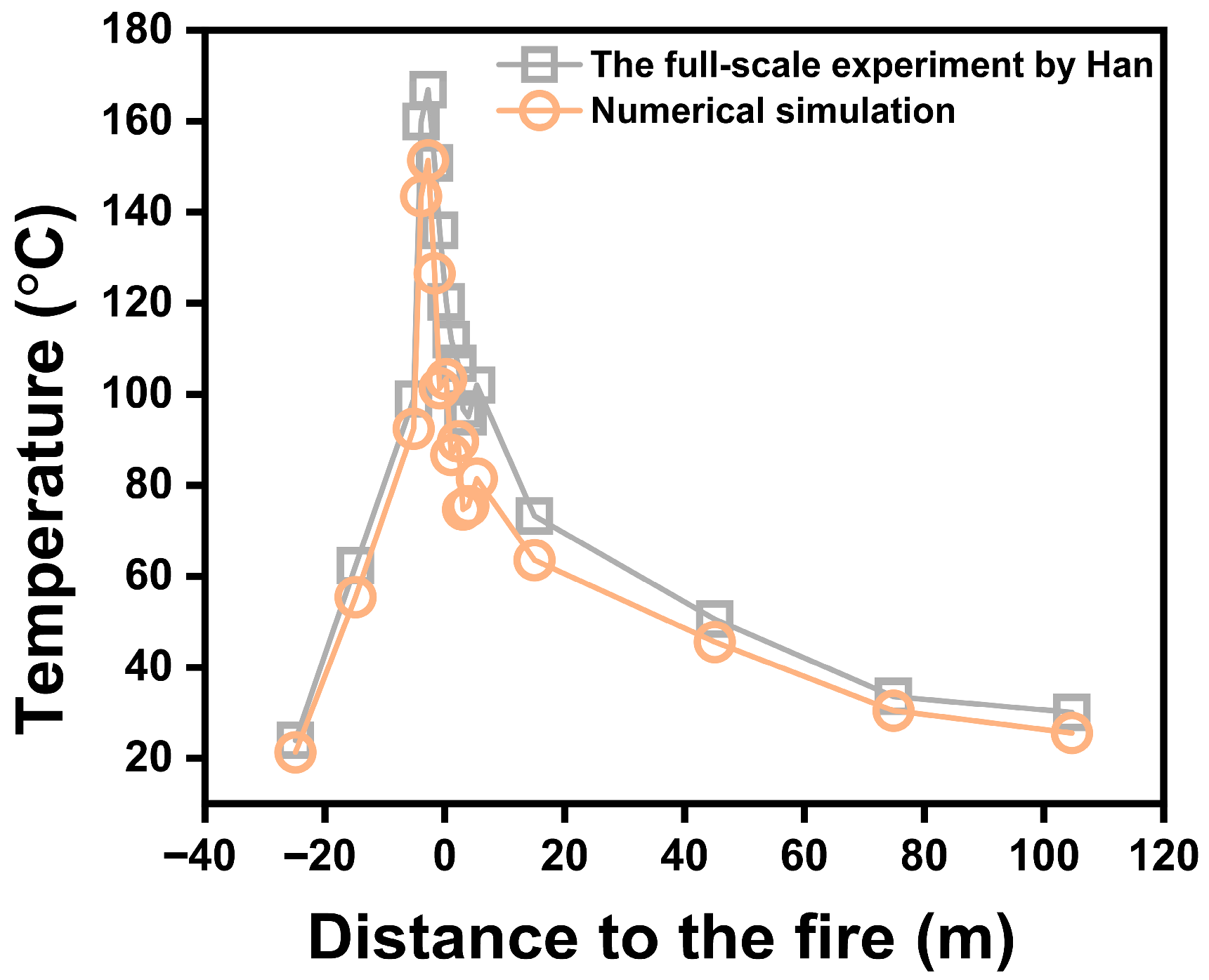
It is worth noting that the predictive capability of FDS for complex flows at the corner of L-shaped tunnels has not been previously validated. Han et al. [25] reported full-scale experiments on ceiling-temperature distributions in connected tunnel configurations that include an L-shaped segment. We compared our numerical simulation results under the same scenario with the experimental results from Han et al., as shown in Figure 2. The comparison demonstrates favorable agreement, suggesting that FDS can reasonably simulate fires in L-shaped tunnels.
Figure 2.
Validation of FDS accuracy in simulating curved tunnels [25].
2.2. Grid Independence Test
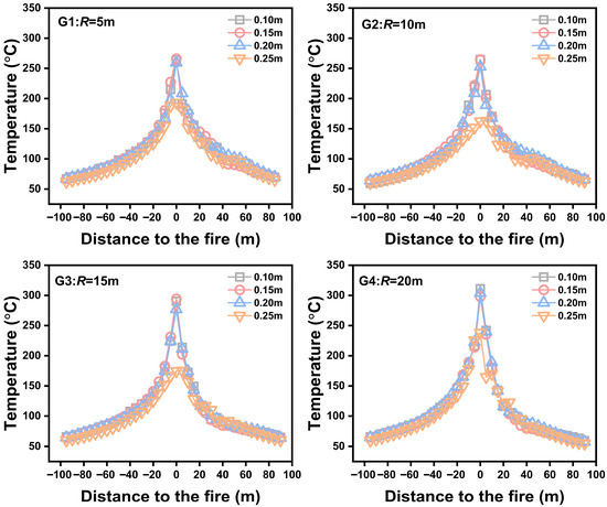
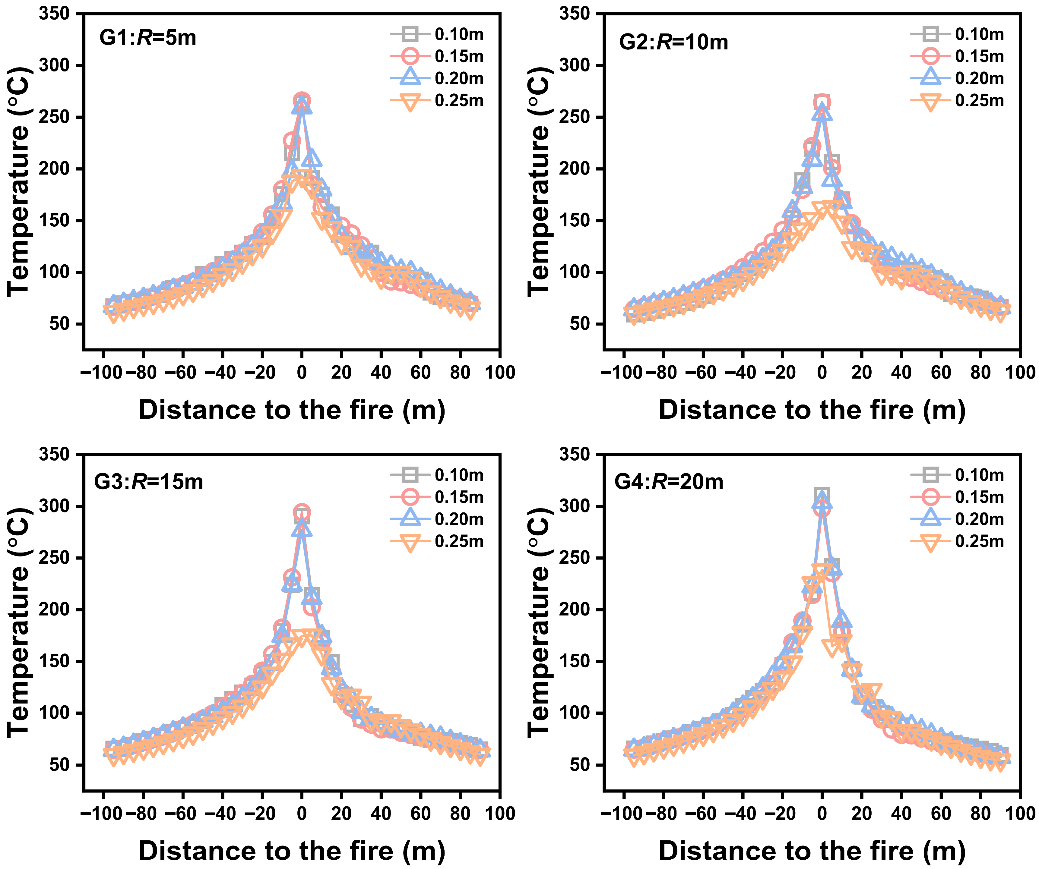
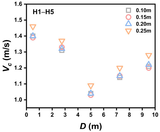
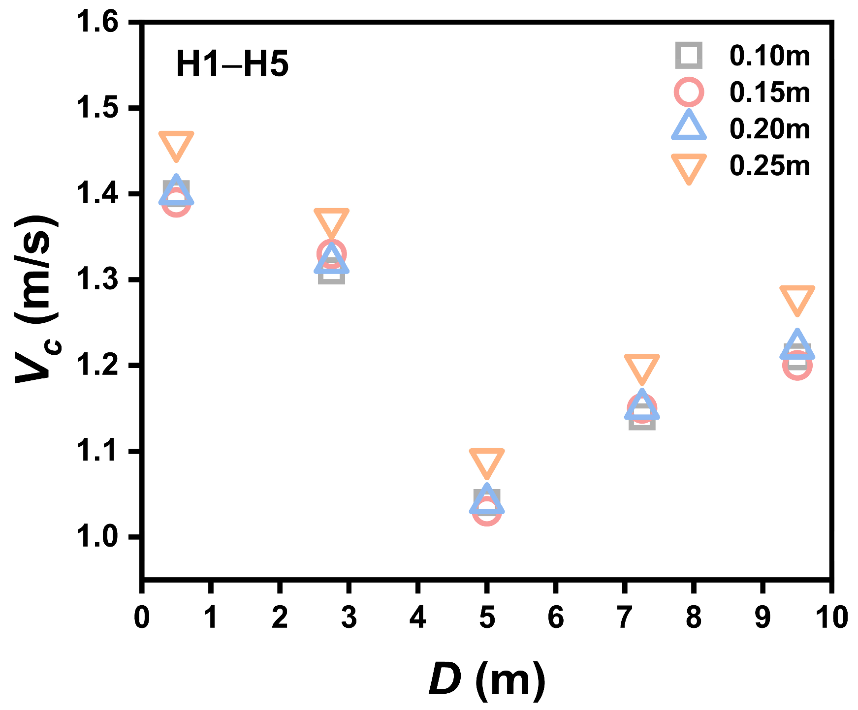
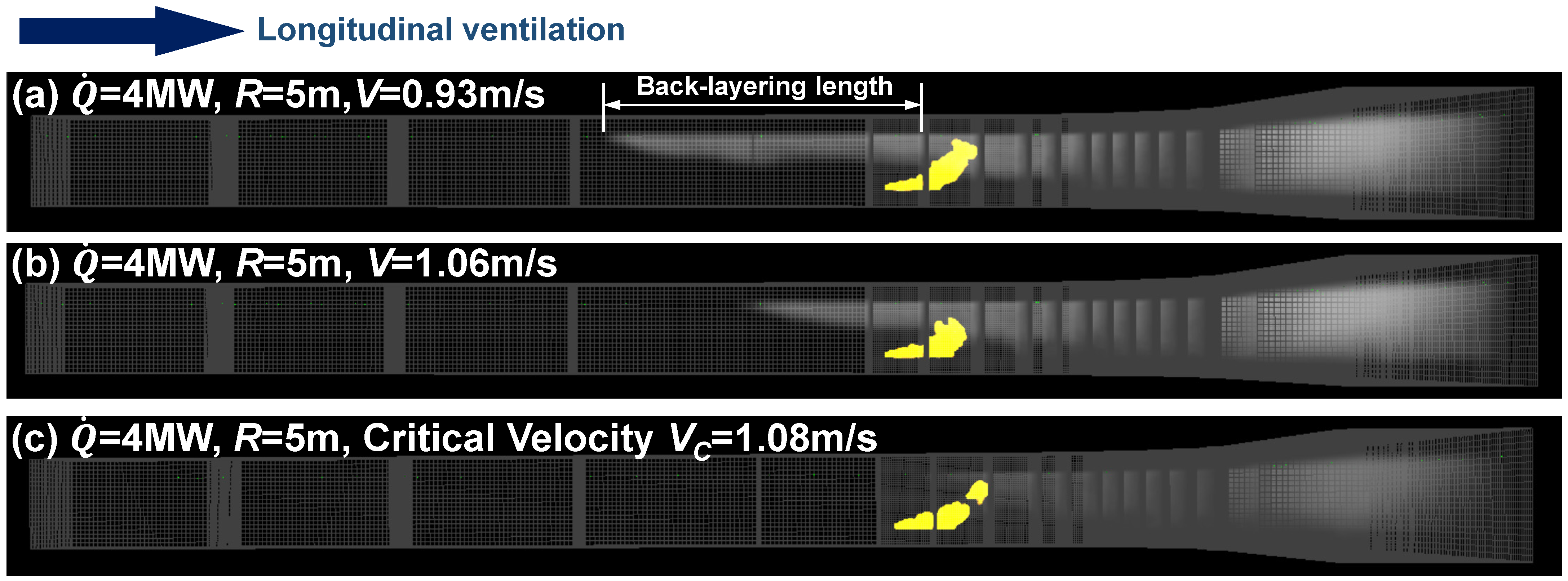
To ensure that variations in mesh resolution did not distort the simulation results, a grid-independence assessment was conducted. Following previous studies, the characteristic length scale was used to determine the appropriate mesh size [26]. When the grid spacing is set within approximately , the numerical error is typically small. According to Equation (1), the representative grid size was calculated to be about 0.16 m. As summarized in Table 1, four meshes (0.10 m, 0.15 m, 0.20 m, and 0.25 m) were tested, and the corresponding results are presented in Figure 3 and Figure 4. For comparison, we examined both the ceiling-jet temperature profile along the tunnel centerline and the critical ventilation velocity (defined using the procedure in Figure 5). The solutions obtained with 0.10, 0.15 m, and 0.20 m grids are essentially consistent, whereas noticeable deviations appear for the 0.25 m case. Balancing accuracy and computational cost, a base grid size of 0.20 m was used in the remaining simulations. Additionally, local refinement to 0.10 m was applied near the fire source and within the curved section to further improve resolution.
Table 1.
Grid independence verification cases.
Figure 3.
Simulation results of longitudinal temperature distribution with different-sized grids.
Figure 4.
Simulation results of critical velocities with different-sized grids.
Figure 5.
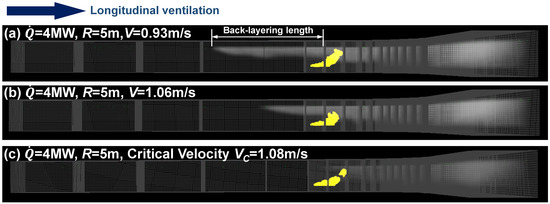
Method for determining critical ventilation velocity.
2.3. Design of Simulation Cases
A series of comparative numerical cases was developed to explore, in a systematic manner, how various factors influence the smoke back-layering length and the critical ventilation velocity. Considering that the transverse position of the fire source significantly influences local air entrainment and near-wall combustion characteristics, thereby affecting smoke-layer stability; that curvature radius determines the centrifugal intensity, wall friction resistance, and velocity field distribution, directly affecting smoke accumulation and backflow behavior in the curved section; the heat release rate governs the buoyancy and momentum strength of the plume; and that longitudinal ventilation plays a controlling role in the occurrence of smoke backflow [27,28]. Therefore, the main parameters examined include heat release rate, lateral fire position, curvature radius, and level of longitudinal ventilation. The full set of simulation conditions is presented in Table 2.
Table 2.
Simulation cases.
3. Theoretical Analysis
3.1. Critical Velocity
The smoke backlayering length is governed by several parameters, including the fire heat release rate , ambient air density , ambient temperature , specific heat of air , gravitational acceleration , longitudinal ventilation velocity , and the hydraulic diameter of the tunnel [29]. Additionally, the tunnel curvature radius , which affects wall friction and centrifugal effects, must also be considered. Prior investigations have confirmed that the combustion behavior of a fire is sensitive to its transverse placement within the tunnel. A fire located near a sidewall experiences reduced air entrainment, resulting in an upward extension of the flame, which may cause it to interact with the ceiling and raise the peak ceiling temperature. Thus, the transverse fire source distance is considered explicitly in the theoretical formulation.
Thus, the back-layering length can be expressed as follows:
Applying dimensional analysis yields the following reformulated version of Equation (2):
When smoke back-layering ceases to occur (i.e., ), the expression simplifies to the following:
where is the dimensionless critical velocity; , represents the dimensionless curvature radius ; and denotes the modified dimensionless heat release rate, corrected by the hydraulic diameter and the fire source position , .
3.2. Smoke Backlayering Length
It has been widely reported that the smoke advance in tunnels ceases when the static pressure at the leading edge of the smoke is counteracted by the ventilation-induced dynamic pressure [30]. At these conditions:
where , .
By invoking the ideal gas equation of state, the relation is obtained as follows:
The governing equations describing smoke flow behavior in a curved tunnel are given as follows [31]:
Continuity equation:
Momentum equation:
Energy equation:
Convective heat transfer is the main mechanism responsible for the ceiling heat loss in tunnels, and it may be described by the following expression:
According to Zhang et al. [32], the heat loss associated with local resistance in a curved tunnel has a proportional relationship with the ceiling heat loss:
By combining Equations (9)–(11), the expression is obtained as follows:
Rearranging Equation (12) yields the following:
Letting , Equation (13) can be rewritten as follows:
By combining Equations (6) and (14), we obtain the following:
From Equation (15), we can derive the following:
In Equation (16), the normalized maximum ceiling temperature rise can be written as follows:
A dimensional analysis of Equation (17) yields the following:
Through the combination of Equations (16) and (18), the smoke back-layering length can be written as follows:
Prior research indicates that typically exhibits a linear dependence on [32]. Therefore, Equation (19) can be rewritten as follows:
where and are empirical coefficients, ; denotes the dimensionless longitudinal ventilation velocity, ; and is the modified dimensionless heat release rate accounting for the tunnel curvature radius and fire source position , .
4. Results and Discussion
4.1. Critical Velocity
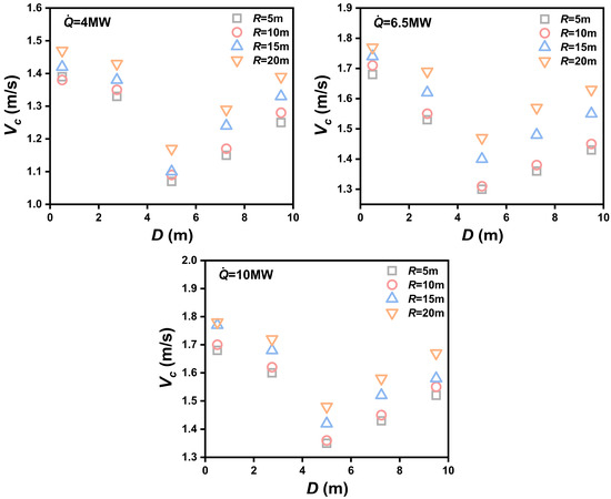
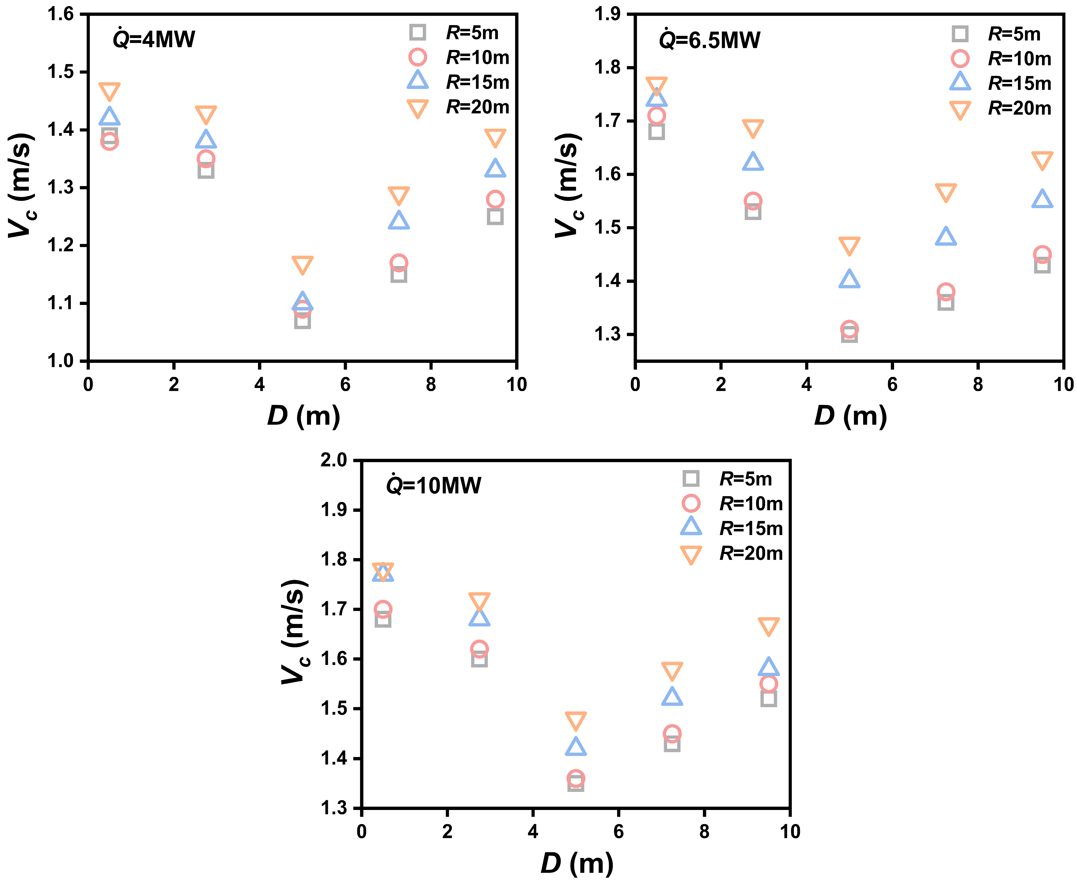
Figure 6 presents the critical velocities under various simulation conditions, from which the following observations can be made:
Figure 6.
Critical velocities of different fire locations.
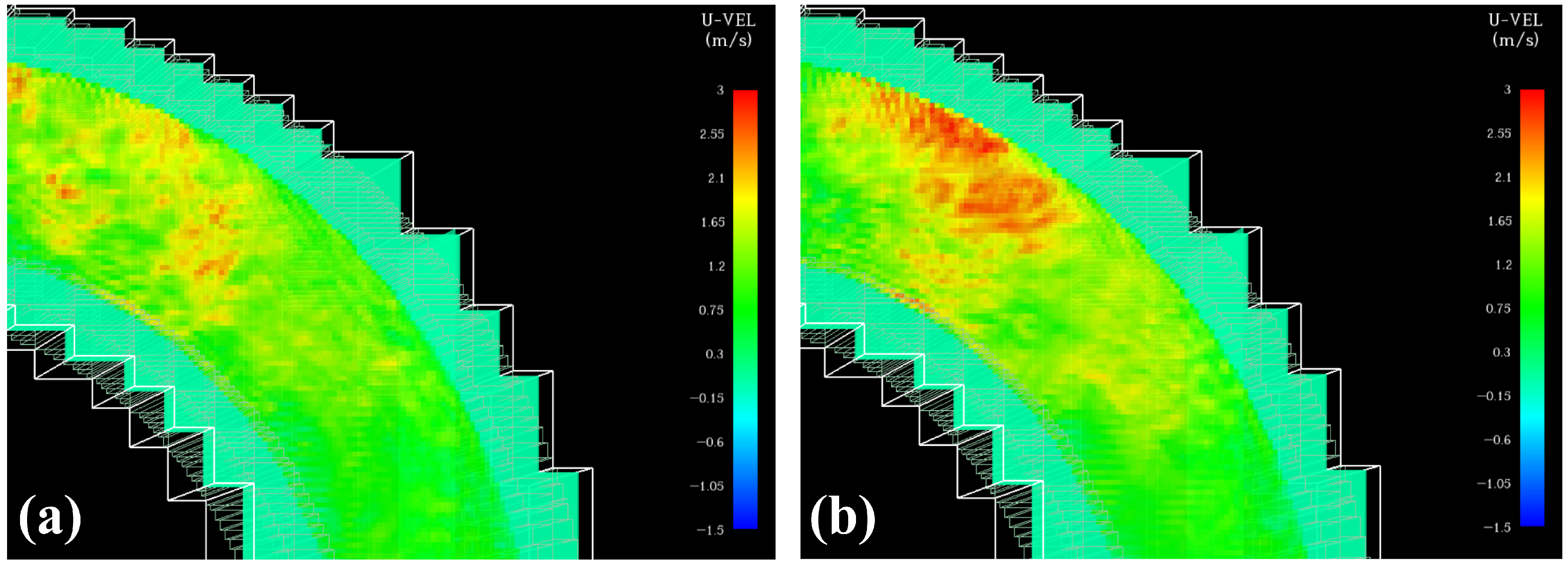
- The variation in critical velocity with fire source offset follows a notable V-shaped behavior. The smallest critical velocity appears when the ignition point is positioned along the tunnel centerline (). As the fire moves closer to either the concave () or convex wall (), a pronounced increase in the critical velocity is observed. For a case with a 10 m curvature radius and a 4 MW heat release rate, the critical velocity reaches 1.09 m/s at the centerline but increases to 1.38 m/s and 1.28 m/s when the ignition point is placed close to the convex and concave walls, respectively. Two key physical reasons explain why the fire’s lateral position influences the critical velocity. First, proximity to a sidewall restricts air entrainment around the flame, lowering combustion efficiency. Such modifications to the smoke concentration and temperature fields disrupt the smoke-layer stability, leading to an increased ventilation demand to eliminate upstream back-layering. Second, in the curved segment, the airflow structure on the concave and convex sides becomes asymmetric (as shown in Figure 7). When the fire is close the concave wall, smoke is driven toward the convex side by centrifugal force, producing a more complex flow pattern. Conversely, when the fire is near the convex side, the local velocity is lower, and smoke accumulation becomes more pronounced. Under both circumstances, the smoke layer becomes asymmetric and less stable, which in turn demands a higher ventilation velocity to restrain smoke propagation effectively.
- With firepower and position held constant, larger curvature radii require higher critical ventilation velocities. Specifically, with a 6.5 MW fire situated near the convex wall, increasing the curvature radius from 5 m to 20 m elevates the critical velocity from 1.68 m/s to 1.77 m/s. Because the curvature radius directly influences the centrifugal force acting on the smoke, a smaller radius (sharper bend) intensifies the centrifugal effect, driving smoke accumulation along the convex wall and potential flow separation near the concave wall. This enhances the interaction between smoke buoyancy and the inertia of longitudinal airflow, thereby slightly weakening upstream back-layering and reducing the required critical velocity. When the curvature radius grows, the centrifugal action on the smoke diminishes, making it necessary to apply a greater ventilation velocity to counteract upstream backflow [33].
- The critical ventilation velocity increases with increasing fire heat release rate. Specifically, for a case where the fire lies on the tunnel centerline and the curvature radius is 10 m, boosting the heat release rate from 4 MW to 10 MW elevates the critical velocity from 1.09 m/s to 1.36 m/s. This trend, consistent with previous findings, arises because a higher heat-release rate strengthens plume buoyancy and upward momentum, intensifying the upstream smoke backflow tendency. Buoyancy can be overcome only by increasing the longitudinal airflow, thereby sustaining a unidirectional smoke flow.
Figure 7.
Velocity distribution in the curved tunnel section: (a) Fire source located at the central axis; (b) Fire source close to the concave wall.
To proceed with deriving the functional dependence of the dimensionless critical velocity, Equation (21) is reformulated as shown below:
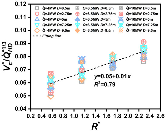
Figure 8 depicts how the normalized critical velocity with the dimensionless curvature radius . Although slight data dispersion is observed in certain regions, a clear overall linear trend of increasing with can still be identified. Accordingly, can be expressed as follows:
Figure 8.
Relationship between the normalized critical velocity and the dimensionless curvature radius.
4.2. Smoke Back-Layering Length
Table 3 summarizes the back-layering lengths obtained under various curvature radii, fire source lateral positions, and longitudinal ventilation velocities. Results indicate that, under identical ventilation conditions, a larger curvature radius leads to a substantially longer back-layering length. For example, when the fire source is located at the tunnel center with a ventilation velocity of 0.95 m/s, increasing the curvature radius from 5 m to 10 m extends the back-layering length from 23 m to 40 m. This trend is consistently observed across different fire source positions. This behavior is primarily governed by the interaction between centrifugal and buoyant forces within the curved section. In tunnels with smaller curvature radii, centrifugal force dominates, driving smoke accumulation along the outer (convex) wall and enhancing local resistance losses. These effects collectively dissipate the upstream momentum of the smoke, thereby reducing the back-layering length. In contrast, as the curvature radius increases, the centrifugal effect weakens, and buoyancy becomes dominant. The excess buoyant momentum counteracts the ventilation flow, allowing the smoke to spread further upstream, resulting in an extended back-layering region.
Table 3.
Smoke back-layering length under selected simulation conditions ().
Furthermore, the lateral position of the fire source exerts a stronger influence on back-layering behavior than the curvature radius. As shown in Table 3, off-center fires near either wall significantly increase the back-layering length. Notably, when the fire source is located adjacent to the convex wall (), the resulting back-layering length is generally larger than that for a concave-wall fire (). For instance, at and a ventilation velocity of approximately 1.35 m/s, the convex-side fire produces a back-layering length of 29 m, whereas no upstream backflow is observed for the concave-side fire.
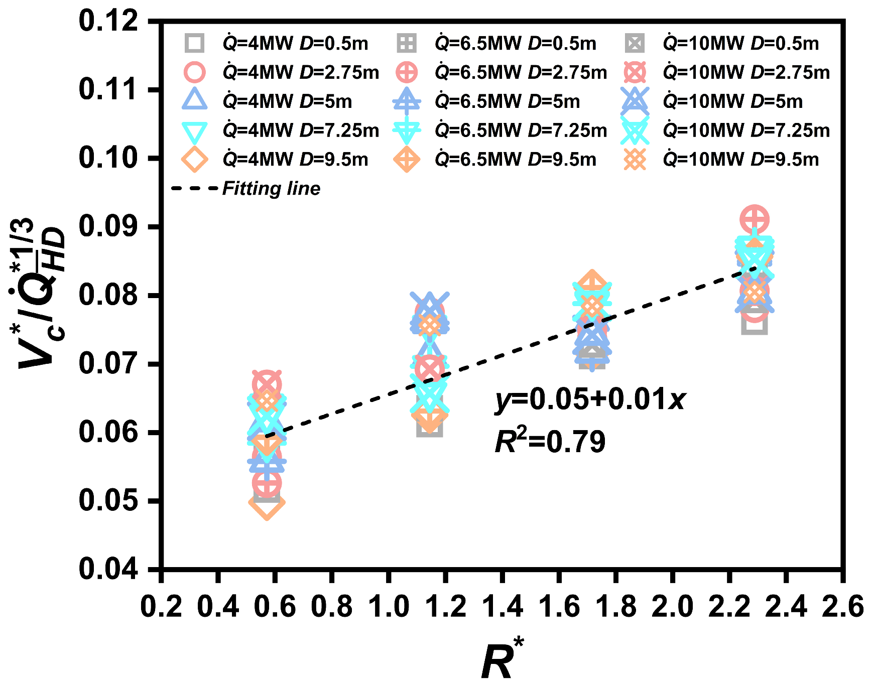
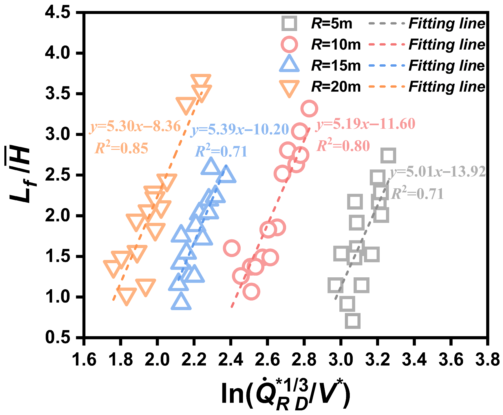
Although the theoretical analysis in Section 3.2 established a predictive expression for the smoke back-layering length, the empirical coefficients and in Equation (20) remain to be determined. As illustrated in Figure 9, a clear linear correlation between and is observed, which agrees well with the theoretical expectation.
Figure 9.
Relationship between and .
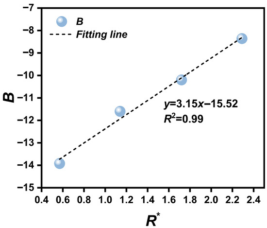
Since the dimensionless heat release rate has been corrected by incorporating the tunnel curvature radius , the coefficient varies only slightly among different curvature radii, remaining nearly constant at around 5.2. In contrast, the coefficient exhibits a noticeable increasing trend with increasing curvature radius. Figure 10 illustrates the dependence of on the dimensionless curvature radius , with a regression fitting used to obtain a quantitative description of this trend.
Figure 10.
Relationship between the coefficient and the dimensionless tunnel curvature radius .
As a result, the predictive formulation for the dimensionless smoke back-layering length is expressed as follows:
5. Conclusions
This work employs numerical modeling and theoretical considerations to clarify the development of the smoke back-layering length and ventilation velocity in L-shaped curved tunnel fire scenarios. The principal findings are outlined as follows:
- (1)
- An increase in heat release rate leads to a higher critical velocity, consistent with classical theory. The fire source’s lateral placement and the tunnel curvature radius also play key roles. When the ignition point is located on the tunnel’s central axis, the critical velocity reaches its lowest value; moving the fire toward either sidewall causes the velocity to rise, forming a clear “V-shaped” pattern. Furthermore, for identical fire conditions, a larger curvature radius corresponds to a higher required critical velocity.
- (2)
- The back-layering length exhibits strong sensitivity to both the curvature radius and the transverse fire source location. Increasing the curvature radius produces a noticeably longer back-layering distance. The fire’s lateral position, however, plays the decisive role: as the fire nears either sidewall, the back-layering length grows sharply, with the maximum value appearing when the fire is placed adjacent to the convex wall.
- (3)
- By integrating the influences of curvature geometry and fire-source offset into the dimensional analysis, a revised form of the dimensionless heat release rate was introduced. This revised parameter enabled the development of a predictive model for the dimensionless critical velocity that reflects the coupled effects of curvature and ignition location. Meanwhile, a theoretical framework was established for evaluating the smoke back-layering length, and the relevant empirical coefficients were obtained by fitting the numerical results.
The predictive models proposed in this study (Equations (23) and (24)) are expected to be applicable only to L-shaped tunnels with aspect ratios similar to those investigated. Their applicability to curved tunnels with larger curvature radii or to sloping helical tunnels requires further verification.
Future research could further investigate smoke spread patterns under the coupling effects of longitudinal ventilation and vertical shaft ventilation and conduct scaled experiments for additional validation.
Author Contributions
Conceptualization, B.M. and W.Z.; methodology, G.C. and B.M.; software, Z.X.; validation, B.M., W.Z. and Z.X.; formal analysis, M.Y.; investigation, B.M., W.Z., G.C. and Z.X.; resources, B.M.; data curation, W.Z.; writing—original draft preparation, W.Z.; writing—review and editing, B.M., G.C. and Z.X.; visualization, M.Y.; supervision, B.M., W.Z., G.C., M.Y. and Z.X.; project administration, B.M.; funding acquisition, B.M. and W.Z. All authors have read and agreed to the published version of the manuscript.
Funding
This research received no external funding.
Institutional Review Board Statement
Not applicable.
Informed Consent Statement
Not applicable.
Data Availability Statement
The original contributions presented in this study are included in the article. Further inquiries can be directed to the corresponding author.
Conflicts of Interest
Authors Wenjie Zhao, Guangyan Chen and Zhuoting Xiao were employed by the company Beijing TianMa Intelligent Control Technology Co., Ltd. Author Bin Miao was employed by the company Zaozhuang Mining Group Co., Ltd. The remaining authors declare that the research was conducted in the absence of any commercial or financial relationships that could be construed as a potential conflict of interest.
References
- Jie, D.; Xu, X.; Guo, F. The future of coal supply in China based on non-fossil energy development and carbon price strategies. Energy 2021, 220, 119644. [Google Scholar] [CrossRef] [Scilit]
- Bartel, S.; Janssen, G. Underground spatial planning—Perspectives and current research in Germany. Tunn. Undergr. Space Technol. 2016, 55, 112–117. [Google Scholar] [CrossRef] [Scilit]
- Lotero, S.; Androulakis, V.; Khaniani, H.; Hassanalian, M.; Shao, S.H.; Roghanchi, P. Optimizing fire emergency evacuation routes in underground coal mines: A lightweight network flow approach. Tunn. Undergr. Space Technol 2024, 146, 105637. [Google Scholar] [CrossRef] [Scilit]
- Villiers, D.J.; Mathews, M.J.; Maré, P.; Kleingeld, M.; Arndt, D. Evaluating the impact of auxiliary fan practices on localised subsurface ventilation. Int. J. Min. Sci. Technol. 2019, 29, 933–941. [Google Scholar] [CrossRef] [Scilit]
- Szlqzak, N.; Obracaj, D.; Korzec, M. Analysis of connecting a forcing fan to a multiple fan ventilation network of a real-life mine. Process Saf. Environ. Prot. 2017, 107, 468–479. [Google Scholar] [CrossRef] [Scilit]
- Bassan, S. Sight distance and horizontal curve aspects in the design of road tunnels vs. highways. Tunn. Undergr. Space Technol. 2015, 45, 214–226. [Google Scholar] [CrossRef] [Scilit]
- Brodny, J.; Tutak, M. Applying computational fluid dynamics in research on ventilation safety during underground hard coal mining: A systematic literature review. Process Saf. Environ. Prot. 2021, 151, 373–400. [Google Scholar] [CrossRef] [Scilit]
- Jafari, S.; Farhanieh, B.; Afshin, H. Numerical investigation of critical velocity in curved tunnels: Parametric study and establishment of new model. Tunn. Undergr. Space Technol. 2023, 135, 105021. [Google Scholar] [CrossRef] [Scilit]
- Kashef, A.; Saber, H.; Gao, L. Optimization of emergency ventilation strategies in a curved section of a road tunnel. In Proceedings of the 13th International Symposium on Aerodynamics and Ventilation of Vehicle Tunnels, New Brunswick, NJ, USA, 13–15 May 2009; pp. 167–181. [Google Scholar]
- An, W.; Tang, Y.; Liang, K.; Cai, M.; Wang, T.; Wang, Z. Study on temperature distribution and CO diffusion induced by cable fire in L-shaped utility tunnel. Sustain. Cities Soc. 2020, 62, 102407. [Google Scholar] [CrossRef] [Scilit]
- Muduli, L.; Jana, P.K.; Mishra, D.P. Wireless sensor network based fire monitoring in underground coal mines: A fuzzy logic approach. Process Saf. Environ. Prot. 2018, 113, 435–447. [Google Scholar] [CrossRef] [Scilit]
- Caliendo, C.; Ciambelli, P.; De Guglielmo, M.L.; Meo, M.G.; Russo, P. Numerical simulation of different HGV fire scenarios in curved bi-directional road tunnels and safety evaluation. Tunn. Undergr. Space Technol. 2012, 31, 33–50. [Google Scholar] [CrossRef] [Scilit]
- Muhasilovic, M.; Deville, M.O. Tunnel-Curvature’s Influence on the Propagation of the Consequences of Large-Scale Accidental Fire-a CFD-Investigation. Turk. J. Eng. Environ. Sci. 2007, 31, 391–402. [Google Scholar]
- Barros-Daza, M.J.; Luxbacher, K.D.; Lattimer, B.Y.; Hodges, J.L. Real Time Mine Fire Classification to Support Firefighter Decision Making. Fire Technol. 2022, 58, 1545–1578. [Google Scholar] [CrossRef] [Scilit]
- Tripathy, D.P.; Parida, S.; Khandu, L. Safety Risk Assessment and Risk Prediction in Underground Coal Mines Using Machine Learning Techniques. J. Inst. Eng. (India) Ser. D 2021, 102, 495–504. [Google Scholar] [CrossRef] [Scilit]
- Ghosh, A. Risk Assessment of Occupational Injuroes in Underground Coal Mines. J. Mines Met. Fuels 2010, 58, 243–248. [Google Scholar]
- Lu, K.; Xia, K.; Shi, C.; Yang, M.; Wang, J.; Ding, Y. Investigation on the Tunnel Curvature Effect upon the Ceiling Temperature of Tunnel Fires: A Numerical Simulation. Fire Technol. 2021, 57, 2839–2858. [Google Scholar] [CrossRef] [Scilit]
- Liu, Y.; Duan, Z.; Cui, Y.; Jiang, F.; Gao, F.; Wang, W. Study on Multi-Parameter Variation of Smoke Flow in Inclined Roadway Fire. Combust. Sci. Technol. 2025, 197, 5701–5720. [Google Scholar] [CrossRef] [Scilit]
- Yao, Y.; Qu, B.; Zhu, H.; Wang, J.; Zhao, S.; Wang, Q. Theoretical and numerical study on critical velocity and driving force for preventing smoke backlayering in a connection roadway fire of coal mines. Tunn. Undergr. Space Technol. 2022, 127, 104566. [Google Scholar] [CrossRef] [Scilit]
- Li, L.; Si, J.; Li, Z. Characteristics of the spatial and temporal evolution of the environmental parameters for belt fire in underground coal mine roadway. Case Stud. Therm. Eng. 2023, 49, 103346. [Google Scholar] [CrossRef] [Scilit]
- Li, B.; Li, Y.; Sun, Y.; Zhang, W.; Li, J.; Zhang, Z.; Cui, Y.; Dong, J.; Liu, H. Study on the influence of forced ventilation on the maximum fire temperature in roadway heading. Sci. Rep. 2025, 15, 9830. [Google Scholar] [CrossRef] [Scilit]
- Peng, S.; Huang, Z.; Dong, D. Numerical Simulation Study On Fire Hazard Of A Coal Mine Transport Roadway. Min. Sci 2022, 29, 33–52. [Google Scholar] [CrossRef] [Scilit]
- Xu, Z.; Zhou, D.; Tao, H.; Zhang, X.; Hu, W. Investigation of critical velocity in curved tunnel under the effects of different fire locations and turning radiuses. Tunn. Undergr. Space Technol. 2022, 126, 104553. [Google Scholar] [CrossRef] [Scilit]
- Hu, L.; Huo, R.; Peng, W.; Chow, W.; Yang, R. On the maximum smoke temperature under the ceiling in tunnel fires. Tunn. Undergr. Space Technol. 2006, 21, 650–655. [Google Scholar] [CrossRef] [Scilit]
- Han, J.; Liu, F.; Wang, F.; Weng, M.; Liao, S. Full-scale experimental investigation on smoke spreading and thermal characteristic in a transversely ventilated urban traffic link tunnel. Int. J. Therm. Sci 2021, 170, 107130. [Google Scholar] [CrossRef] [Scilit]
- Wang, Z.; Zhu, L.; Guo, X.; Pan, X.; Zhou, B.; Yang, J.; Jiang, J.; Hua, M.; Feng, L. Reduced-scale experimental and numerical study of fire in a hybrid ventilation system in a large underground subway depot with superstructures under fire scenario. Tunn. Undergr. Space Technol. 2019, 88, 98–112. [Google Scholar] [CrossRef] [Scilit]
- Caliendo, C.; Russo, I.; Genovese, G. CFD Modeling to Evaluate User Safety by Using Flame Retardants in Asphalt Road Pavements during Large Tunnel Fires. CMES—Comput. Model. Eng. Sci. 2025, 144, 693–715. [Google Scholar] [CrossRef] [Scilit]
- Emori, R.I.; Saito, K. A Study of Scaling Laws in Pool and Crib Fires. Combust. Sci. Technol. 1983, 31, 217–231. [Google Scholar] [CrossRef] [Scilit]
- Guo, J.; Cai, G.; Liu, Y.; Wen, H.; Jin, Y. Temperature distribution and characteristics induced by fire smoke in L-shaped utility tunnels with small curvature radii. Case Stud. Therm. Eng. 2021, 28, 101470. [Google Scholar] [CrossRef] [Scilit]
- Chow, W.K.; Gao, Y.; Zhao, J.H.; Dang, J.F.; Chow, C.L.; Miao, L. Smoke movement in tilted tunnel fires with longitudinal ventilation. Fire Saf. J. 2015, 75, 14–22. [Google Scholar] [CrossRef] [Scilit]
- Kunsch, J.P. Critical velocity and range of a fire-gas plume in a ventilated tunnel. Atmos. Environ. 1999, 33, 13–24. [Google Scholar] [CrossRef] [Scilit]
- Zhang, S.; Yang, H.; Yao, Y.; Zhu, K.; Zhou, Y.; Shi, L.; Cheng, X. Numerical Investigation of Back-Layering Length and Critical Velocity in Curved Subway Tunnels with Different Turning Radius. Fire Technol. 2017, 53, 1765–1793. [Google Scholar] [CrossRef] [Scilit]
- Wang, F.; Wang, M.; Carvel, R.; Wang, Y. Numerical study on fire smoke movement and control in curved road tunnels. Tunn. Undergr. Space Technol. 2017, 67, 1–7. [Google Scholar] [CrossRef] [Scilit]
- Wu, Y.; Bakar, M.Z.A. Control of smoke flow in tunnel fires using longitudinal ventilation systems—A study of the critical velocity. Fire Saf. J. 2000, 35, 363–390. [Google Scholar] [CrossRef] [Scilit]

Disclaimer/Publisher’s Note: The statements, opinions and data contained in all publications are solely those of the individual author(s) and contributor(s) and not of MDPI and/or the editor(s). MDPI and/or the editor(s) disclaim responsibility for any injury to people or property resulting from any ideas, methods, instructions or products referred to in the content. |
© 2025 by the authors. Licensee MDPI, Basel, Switzerland. This article is an open access article distributed under the terms and conditions of the Creative Commons Attribution (CC BY) license.