


Abstract
To realize the remanufacturing of cast iron components, a WC-reinforced Fe-based composite powder was designed, and the WC/Fe-based composite coating was deposited on the HT250 substrate by laser cladding. The melting and dissolution mechanism of WC ceramic particles were investigated, and their influences on the microstructure, phase, microhardness, and wear resistance of the composite coatings were systematically analyzed. The results show that the WC/Fe-based composite coating achieves good metallurgical bonding with the HT250 substrate and possesses excellent forming quality. The incorporated WC particles can effectively optimize the microstructural morphology, acting as heterogeneous nucleation sites and inhibiting grain growth. As WC content increases, the grain size within the composite coating gradually refines. Moreover, partially melted WC particles release tungsten (W) and carbon (C) elements into the molten pool, promoting the in-situ generation of new hard phases, including W2C and Fe6W6C. These newly formed phases, together with the residual unmelted WC particles, contribute a dispersion strengthening effect and improve the properties of the composite coatings. This effect becomes more pronounced with higher WC content. Notably, the composite coating with 20% WC exhibits a microhardness over twice that of the HT250 substrate, while its wear rate is only one-sixth that of the substrate and its corrosion resistance is much higher than that of the HT250 substrate.
1. Introduction
Owing to its excellent castability, effective vibration damping capacity, and reliable thermal stability and cost-effectiveness, gray cast iron (GCI) has been extensively applied in industrial fields, including automotive manufacturing, machine tool production, and power systems [1,2,3]. Nevertheless, under prolonged service conditions characterized by high friction, heavy loads, and high dust exposure, the surfaces of GCI components (e.g., engine cylinder blocks, machine tool guides, hydraulic cylinder blocks, and large bearing housings) are prone to wear or fatigue failure. Directly scrapping such mechanical parts would not only generate significant material waste but also entail considerable economic losses.
Conventional repair techniques, including arc welding, argon arc welding, and spraying, suffer from inherent limitations such as excessive heat input, severe structural distortion, and insufficient interfacial bonding strength [4,5,6]. In contrast, as an advanced additive manufacturing and surface strengthening technology, laser cladding has opened up new technological avenues for the green remanufacturing and performance enhancement of mechanical parts, delivering significant economic and environmental benefits [7,8,9]. This technique offers the advantages of a narrow heat-affected zone, minimal thermal deformation, high process controllability, and dense metallurgical bonding [10]. Given these advantages, laser cladding has been increasingly explored for the repair and surface improvement of various industrial components. Abhinava et al. [11] deposited a Co-based Stellite-6 alloy coating on gray cast iron brake disc surfaces via laser cladding. The resulting coating exhibited good wear resistance, with a maximum wear rate reduction of up to 43% relative to the substrate. Xv et al. [12] adopted high-speed laser cladding to apply Fe-Cr-Ni coatings on the casings of the hydraulic support columns in a coal mining machine, aiming to enhance their wear and corrosion resistance. In addition, a coating quality prediction model was established based on the AdaBoost algorithm. Raj et al. [13] repaired the damaged surface of 410 stainless steel turbine blades by laser cladding pure nickel alloy coating and achieved defect-free metallurgical bonding. In another study, Liu et al. [14] carried out the repair of 316L piston rods by laser cladding Ni60 alloy on their worn surfaces. The correlations among main process parameters, coating geometry, and formation quality have been established.
The properties of laser-cladded coatings are largely governed by the characteristics of the powder used in laser cladding. Among the various alloy powders available, Fe-based, Co-based, and Ni-based powders represent typical self-fluxing alloy powders. These powders possess deoxidation and slagging capabilities and are widely utilized in thermal spraying, laser cladding and additive manufacturing [15,16]. The Ni-based and Co-based alloy powders are commonly adopted for laboratory research. By contrast, the Fe-based powder has a cost advantage and is more suitable for large-scale practical engineering applications. According to our procurement records, the price of Fe-based powder merely accounts for one-fifth or even one-eighth of that of Ni- or Co-based counterparts. Consequently, laser cladding utilizing Fe-based alloy powders has attracted increasing attention in the field of mechanical remanufacturing [17]. Xie et al. [18] laser cladded an Fe-based alloy coating on Cr2Ni4MoV steel. Tests showed that the coating achieved a reduced dry friction coefficient and wear volume relative to the substrate, with a shear strength up to 280.83 MPa. Wang et al. [19] sexplored laser cladding of Fe-based alloy coating on 42CrMo steel, and the result revealed that a laser power of 1800 W yielded the coating with superior corrosion resistance. In addition, Zhang et al. [20] designed Fe-based gradient coatings on U75V railway steel, which delivered remarkable enhancement in wear resistance.
However, under severe conditions involving sliding wear, impact wear and abrasive wear, pure Fe-based alloys no longer meet the service requirements. For this reason, it is imperative to incorporate ceramic particles as reinforcing phases into Fe-based alloy powders to comprehensively improve their mechanical and tribological properties [21]. Currently, the most widely used ceramic reinforcements mainly include Al2O3, SiC, WC, and TiC [22,23,24]. Among these ceramic candidates, WC ceramic particles exhibit superior characteristics, including a high melting point, superior hardness, and a low thermal expansion rate [25]. Furthermore, WC exhibits excellent chemical compatibility with self-fluxing alloys, enabling the formation of stable interfacial bonding between the reinforcement and the alloy substrate. Accordingly, WC has been widely recognized as an ideal reinforcing phase for composite coatings to ameliorate their overall service performance [26,27,28]. In terms of WC-reinforced iron-based composite coatings, some relevant studies have been reported in recent years. For instance, Cao et al. [29] prepared WC/Fe-based composite coatings on 45 steel and effectively suppressed the cracking tendency by optimizing the powder composition. Wei et al. [30] developed WC/Fe-based coatings aimed at the damage repair of 40Cr gear spline shafts. In addition, Bartkowski et al. [31] laser cladded a WC/Fe-based composite coating on the low-carbon steel and investigated the influence of processing parameters on the coating formation.
The incorporation of WC ceramic particles can effectively enhance the comprehensive performance of laser-cladded coatings. Reasonable adjustment of WC content enables active control over the coating characteristics and inhibits the formation of internal defects. Nevertheless, the underlying modification mechanism of WC particles on the microstructure and mechanical properties of WC/Fe-based composite coatings has not been fully revealed. Meanwhile, HT250 cast iron has high carbon equivalent and poor plasticity, which makes it more susceptible to cracking during the deposition of alloy coatings. Accordingly, it remains challenging to laser-clad crack-free coatings on HT250 material, and related research is relatively scarce. Against this background, Fe-based composite coatings with different WC mass fractions were prepared on HT250 substrates by laser cladding in this work. The melting behavior of WC particles and their interaction mechanism with Fe-based alloys were systematically characterized. Furthermore, the influences of WC particles and their content on the microstructure evolution, phase composition, and mechanical properties of WC/Fe-based composite coatings were investigated in detail. From the perspective of sustainability and economic practicality, this work can establish a theoretical and experimental foundation for the practical remanufacturing and surface modification of critical cast iron components.
2. Materials and Methods
2.1. Coating Preparation
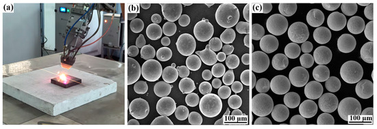
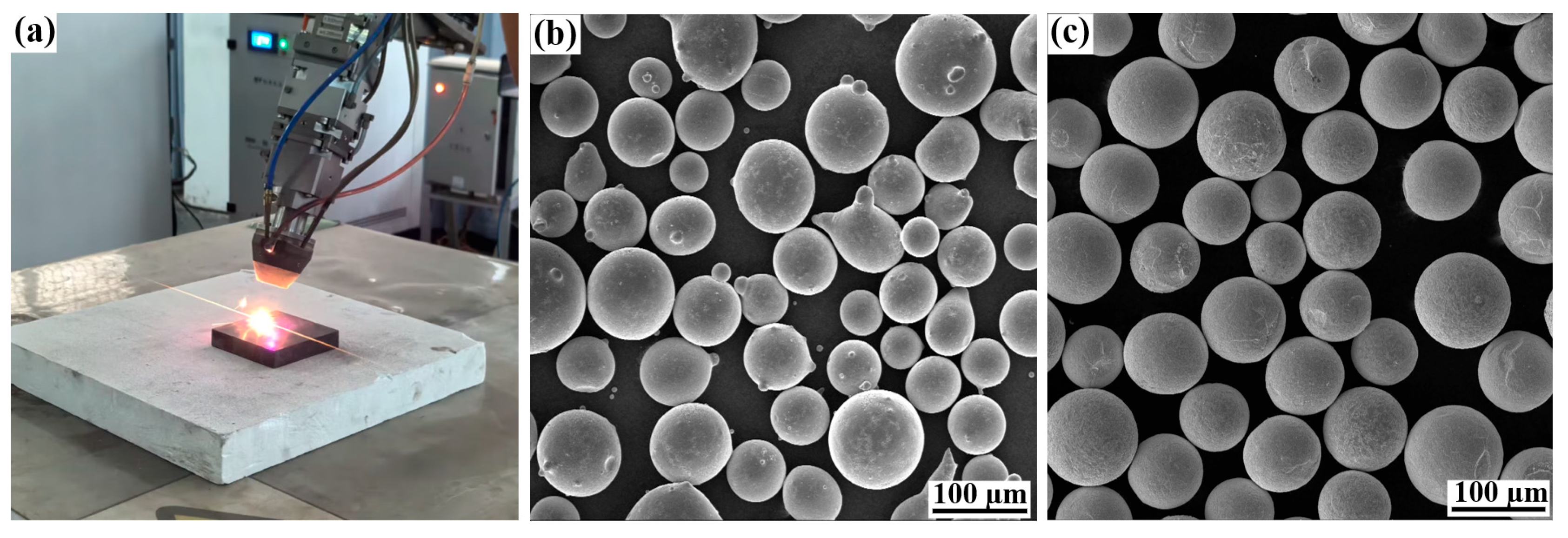
The coating was prepared by the laser cladding system with an LDF-3000-60 semiconductor laser (Laserline Laser Technology Co., Ltd., Shanghai, China), as illustrated in Figure 1a. The substrate material is HT250 gray cast iron. The laser cladding powders are composite powders mixed with Fe-based alloy powders and WC ceramic powders. The morphology of the Fe-based alloy powder and the WC ceramic particles is shown in Figure 1b,c, and their particle size ranges are 58–150 µm and 48–106 µm, respectively. The chemical compositions of the HT250 substrate and the Fe-based powder are given in Table 1.
Figure 1.
(a) Schematic diagram of laser cladding experiment; (b) Fe-based alloy powder; (c) WC ceramic particles.
Table 1.
Chemical composition of different materials (wt./%).
The optimal process parameters of laser cladding obtained by preliminary tests are as follows: Laser power of 1.5 kW, scanning speed of 5 mm/s, powder feed rate of the turntable of 6 g/min, and overlap rate of 40%. The laser spot diameter is fixed at 3 mm. As reported in our previous work [32], excessive WC content reduces coating compactness and promotes CO/CO2 gas evolution, increasing the susceptibility to cracking and porosity. Therefore, WC mass fractions were set at 0%, 10%, 15%, 20%, 25%, and 30% to prepare WC/Fe-based composite coatings by laser cladding.
2.2. Performance Testing
2.2.1. Microstucture
The prepared coatings were cut by an electric discharge cutting machine and then processed into test specimens. The microstructure of the specimens was observed by an inverted metallographic microscope (LWD300LCS, Cewei Optoelectronic Technology Co., Ltd., Xi’an, China) and a scanning electron microscope (SEM, TESCAN MIRA4, TESCAN Trading Co., Ltd., Shanghai, China). The phase constituents and chemical compositions were tested using an X-ray diffractometer (XRD, DX-2700BH, Haoyuan Instrument Co., Ltd., Dandong, China) with a scanning range of 2θ = 20–90° and an energy dispersive spectrometer (EDS, Xplore30, TESCAN Trading Co., Ltd., Shanghai, China), respectively.
2.2.2. Microhardness
The cross-section microhardness of the specimens was measured by a Vickers hardness tester (HV-1000STA, Cewei Optoelectronic Technology Co., Ltd., Xi’an, China) with an applied load of 0.5 kgf and a dwell time of 15 s. At each measured position, three indentations were made, and the average hardness value was calculated to minimize testing errors.
2.2.3. Tribological Tests
In addition, tribological tests for the substrate and coatings with different WC contents were performed using the Rtec MFT-5000 reciprocating tribometer (Aitec Instrument Technology Co., Ltd., Nanjing, China). Each material had three independent specimens for repeated tests to obtain mean values and standard deviations. In the tests, a 6 mm diameter ZrO2 ceramic ball was used as the counter-body, with a unidirectional sliding length of 6 mm, a reciprocating frequency of 2 Hz, an applied load of 50 N, and a holding time of 1200 s. The coefficient of friction (CoF) was recorded throughout the process. After testing, three-dimensional optical surface profiles of the worn specimens were captured using a VK-X100 confocal microscope (KEYENCE Co., Ltd., Shanghai, China) and the wear depths were measured to calculate the corresponding wear volumes.
The wear rate is expressed as follows [33]:
where, W is the wear rate, ΔV is the wear volume, Fz is the applied load, and S is the total sliding distance.
2.2.4. Corrosion Tests
The electrochemical corrosion test was conducted for the substrate and coatings with different WC contents using the CS310M electrochemical workstation (Wuhan Corrtest Instruments Corp., Ltd., Wuhan, China) at room temperature. Each material had three specimens for testing to ensure the reliability of the results. The corrosion fluid was a 3.5% NaCl solution. For polarization curve measurements, the electrode assembly was immersed in the test solution for 30 min after connection. Scanning was initiated once the open-circuit potential (OCP) stabilized, with a scanning voltage window of −0.5 V to 1 V relative to OCP and a scan rate of 1 mV/s. For electrochemical impedance spectroscopy (EIS) tests, the scan frequency was set from 100 kHz to 10 mHz, and a sinusoidal AC perturbation signal with an amplitude of 10 mV was applied.
3. Results and Discussion
3.1. Coating Macro-Morphology
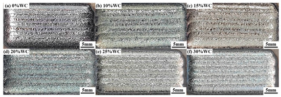
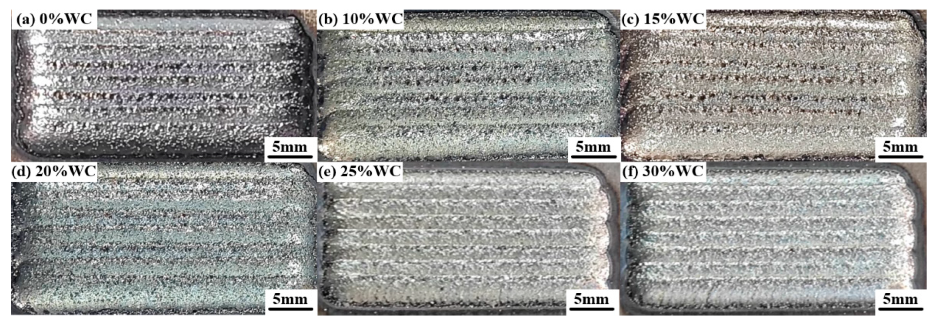
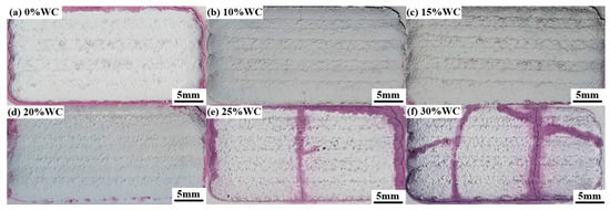
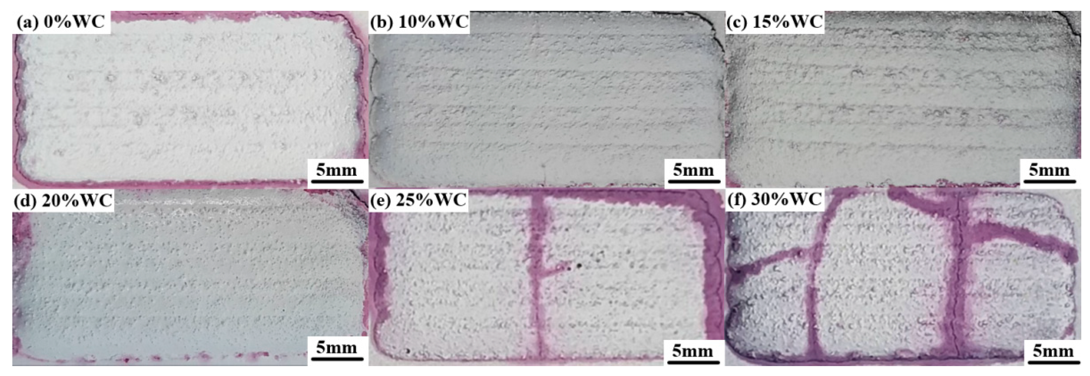
The surface morphology and crack detection of as-fabricated composite coatings with different WC contents are shown in Figure 2 and Figure 3, respectively. From Figure 2, it can be seen that all coating surfaces are flat and smooth. However, from the crack detection in Figure 3, it can be seen that cracks appeared when the WC content reached 25%, and the number of cracks increased when the WC content increased to 30%. Therefore, this article selects coatings with WC addition ranging from 0% to 20% as the analysis object.
Figure 2.
Surface morphology of WC/Fe-based composite coatings with varying WC contents.
Figure 3.
Crack detection of WC/Fe-based composite coatings with varying WC contents.
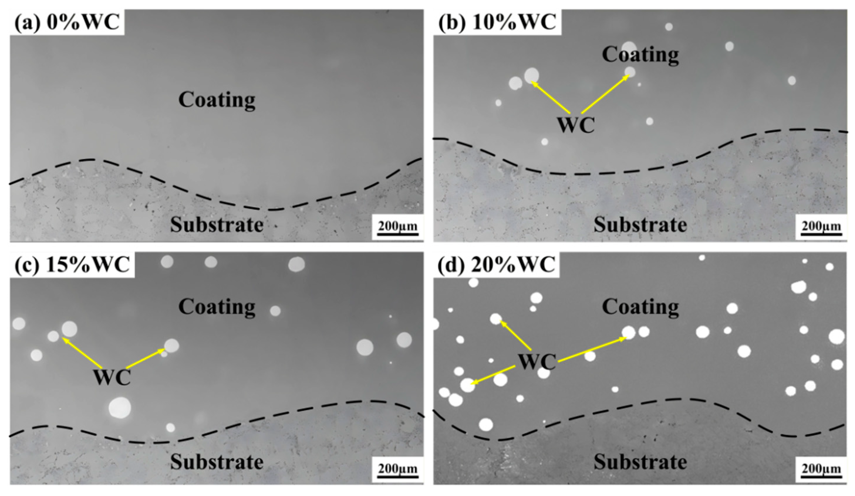
Their cross-section morphologies are illustrated in Figure 4. The WC/Fe-based composite coating forms sound metallurgical bonding with the HT250 substrate, and there are no cracks or pores on the polished cross-sections. Meanwhile, nearly all WC particles retain their spherical morphology and distribute uniformly within the coatings.
Figure 4.
Cross-section morphology of WC/Fe-based composite coatings with varying WC contents.
3.2. Microstructure Evolution
To investigate the effects of WC content on the microstructure of the WC/Fe-based composite coatings, the microstructure close to and distant from the WC particles was observed.
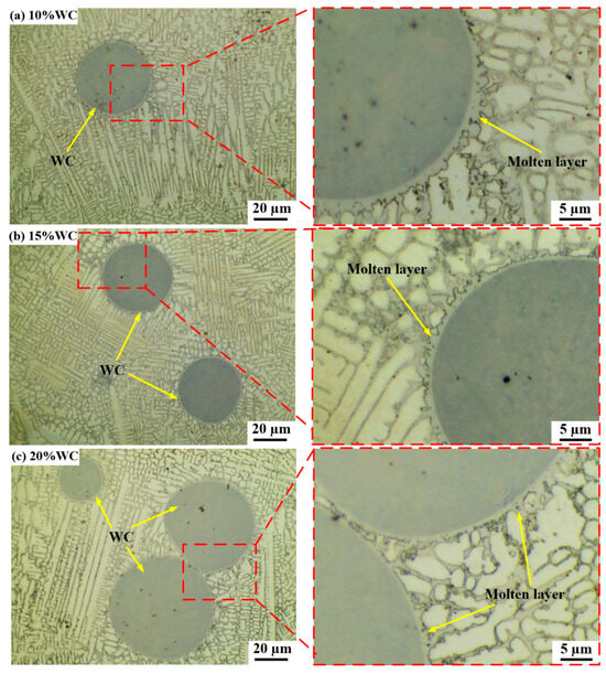
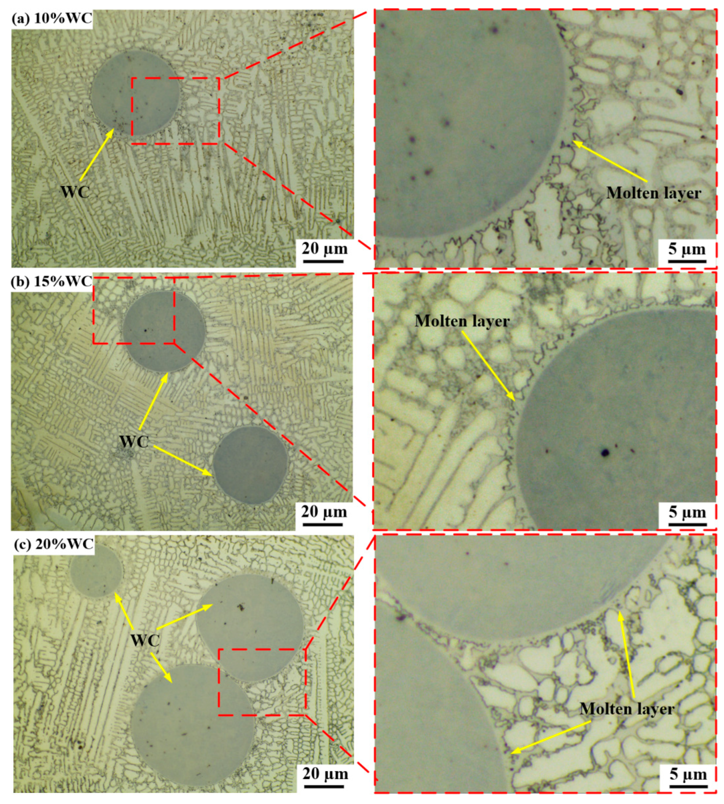
Figure 5 shows the microstructure of the composite coatings adjacent to WC particles. As observed, WC particles serve as heterogeneous nucleation cores and markedly restrain the oriented propagation of columnar grains, resulting in the formation of finely dispersed irregular cellular structures and dendrites around them. Meanwhile, it can be seen from the enlarged views that a flocculent layer forms on the outer periphery of WC particles, which indicates melting of the WC surface followed by outward elemental diffusion.
Figure 5.
Microstructures adjacent to WC particles in coatings with different WC contents: (a) 10% WC; (b) 15% WC; (c) 20% WC.
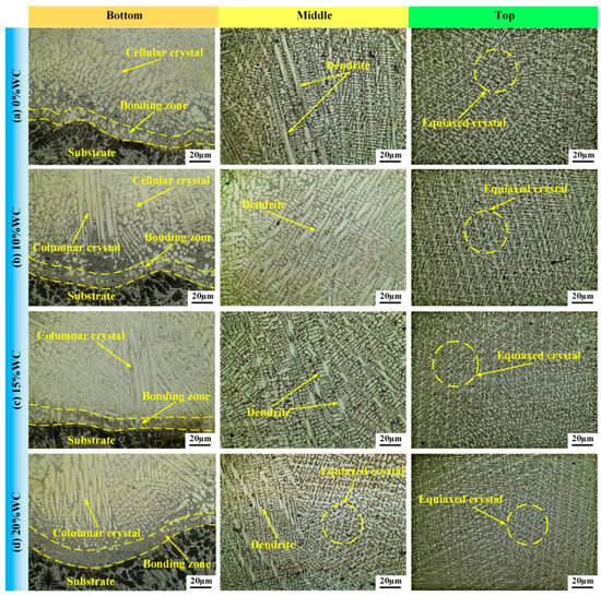
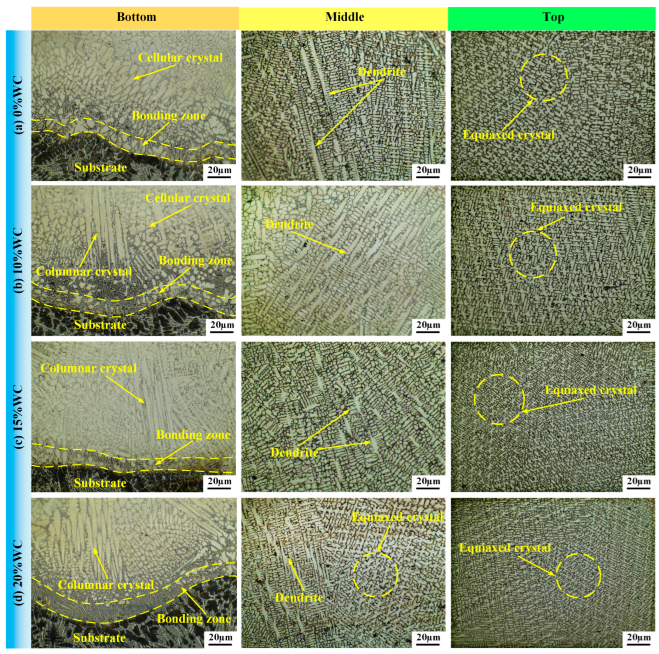
Figure 6 presents the microstructural features of composite coatings distant from WC particles from bottom, middle, and top positions. At the coating bottom, the 0% WC coating is dominated by cellular crystals, while coatings with 10%, 15%, and 20% WC form columnar grains normal to the bonding line. As WC content rises, columnar grains grow more abundant yet shorter in length. In addition, a thin layer of fine planar crystals forms at the bonding zone due to the large temperature gradient, indicating that the coating has formed a dense metallurgical bonding with the HT250 substrate. In the middle region of the coatings, abundant dendritic grains together with a small fraction of equiaxed grains can be observed. Since heat is mainly conducted into the substrate, slow heat dissipation lowers the temperature gradient and solidification speed, triggering the transition from columnar to dendritic microstructure and promoting dendritic growth opposite to the heat flow. When the WC content rises from 0% to 20%, the quantity and length of dendritic grains decline, accompanied by an increase in equiaxed grains. The top region of the coatings is dominated by equiaxed grains. The coating surface is in contact with ambient air, with a large temperature gradient and a high solidification rate, so it is easy to form small equiaxed crystals.
Figure 6.
Microstructures at the top, middle and bottom regions distant from WC particles in coatings with different WC contents: (a) 0% WC; (b) 10% WC; (c) 15% WC; (d) 20% WC.
Overall, the equiaxed grain size decreases with the increase in WC content. For one thing, the increased WC enhances the undercooling level during the solidification process of the molten pool and reduces the critical nucleation radius, leading to grain refinement. For another, WC particles undergo partial melting at high temperatures and release W atoms that combine with Fe and C in the melt to form hard carbides. These hard carbides, along with the unmelted WC particles, can serve as heterogeneous nucleation cores for α-Fe to increase the nucleation rate and suppress grain growth, thereby promoting grain refinement.
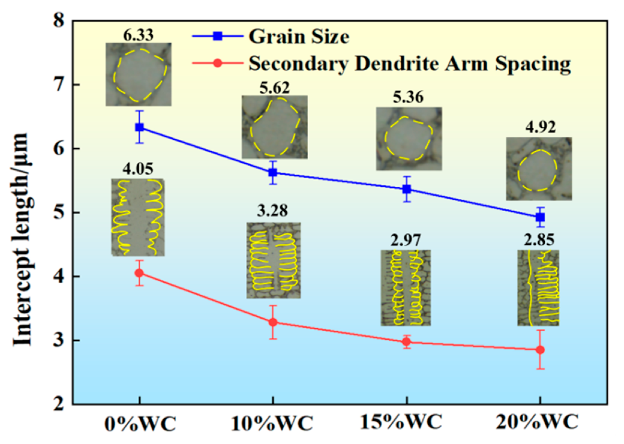
Furthermore, to clarify how WC affects microstructure refinement, quantitative measurements of grain size and secondary dendrite arm spacing (SDAS) were performed on the composite coatings. Referring to the microstructures in Figure 6, grain size was calculated in the top regions, and SDAS was measured in the middle regions of the coatings.
According to the international standard ASTM E112, the single circular intercept technique was adopted for grain size measurement. The test circles were scattered over the testing region to achieve a minimum of 35 intercepts along each perimeter. If one circular line intersects three grain boundaries, two intercept counts are recorded, and the final grain size is calculated as follows [34]:
where is the average grain size, Lc is the length of the circumference, M is the magnification factor of the field view, and Pi is the number of intersection points between the measuring line and the grain boundary.
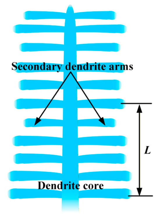
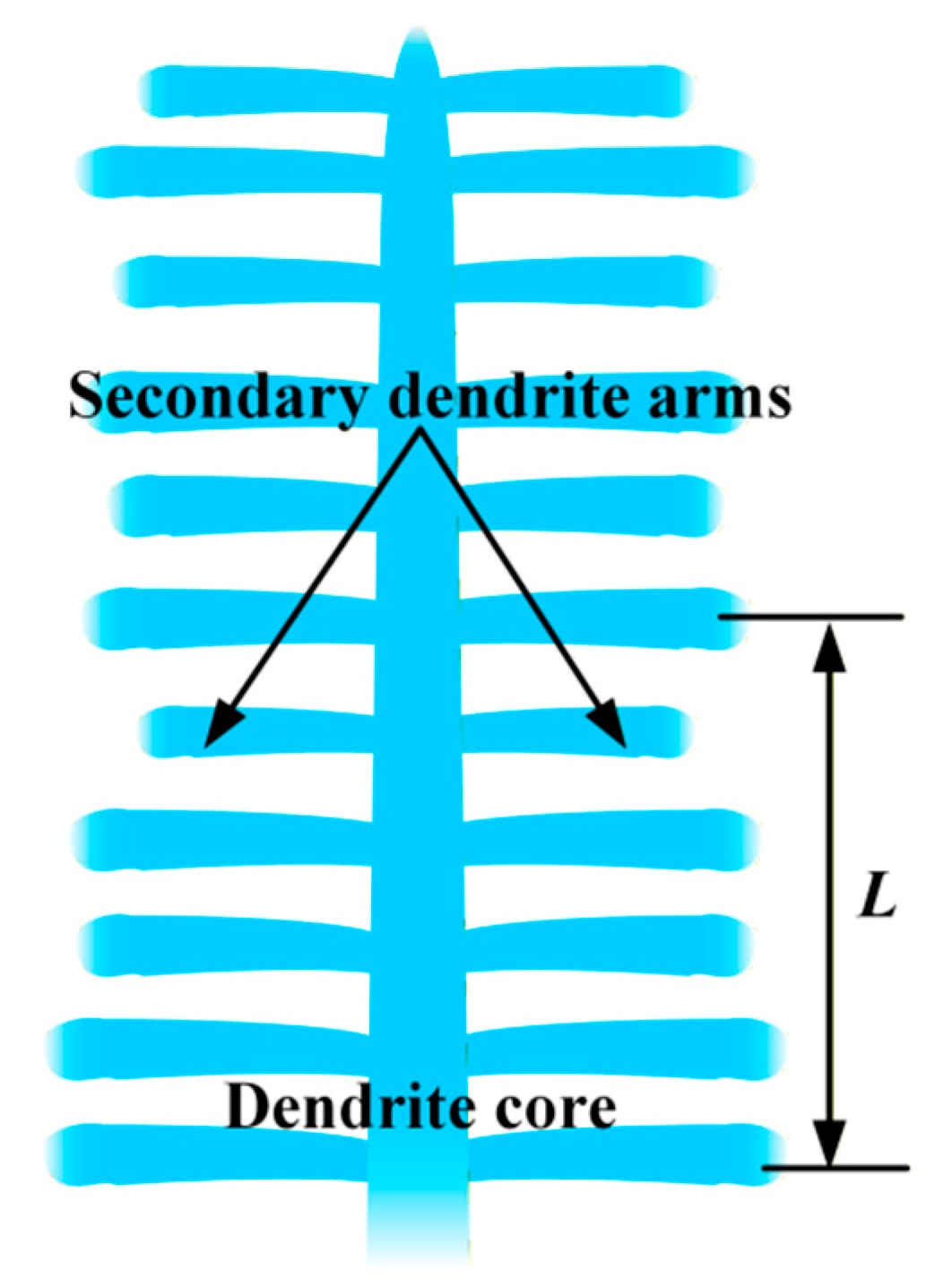
The linear intercept method is used to measure the SDAS. As shown in Figure 7, the secondary dendrites are evenly distributed on both sides of the main dendrite stem. Draw a test line vertical to the direction of secondary dendrite growth and measure its length (L), and then count the number (N) of dendrite arms. Therefore, the SDAS (σ) is calculated as follows [35]:
Figure 7.
Diagram of SDAS measurement.
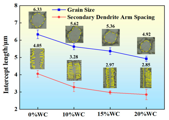
For both grain size and SDAS measurements, the final result was averaged from ten parallel measurements to minimize statistical errors. Figure 8 presents the measured average grain size and SDAS values for coatings with varying WC contents. With WC mass fraction increasing from 0% to 20%, grain size falls from 6.33 μm to 4.92 μm, and SDAS also declines from 4.05 μm to 2.85 μm. This indicates that increasing WC addition can promote grain refinement.
Figure 8.
Measured results of average grain sizes and SDAS.
3.3. Phase Identification
3.3.1. Decomposition of WC Particles
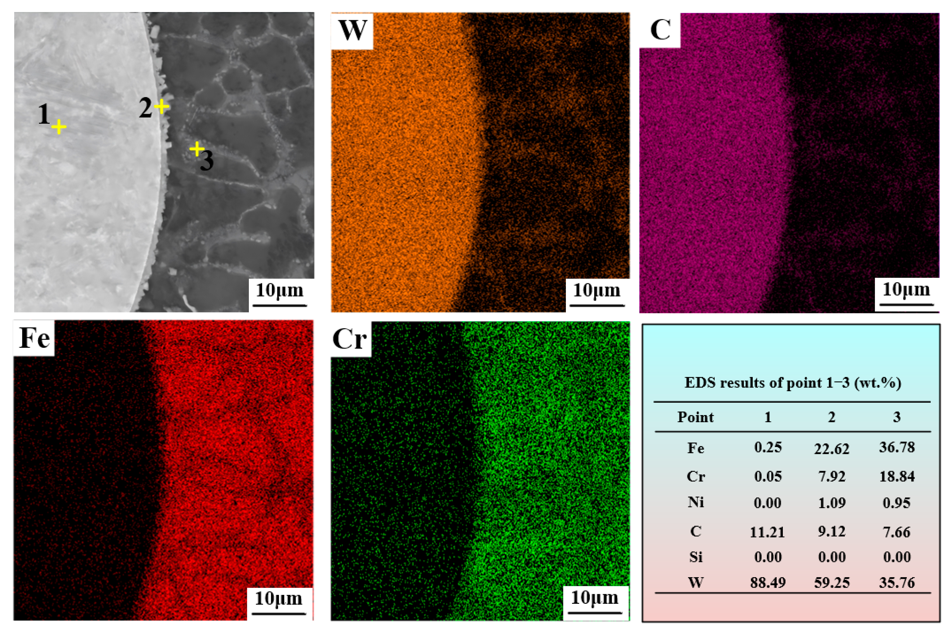
WC particles possess a melting point exceeding 2800 °C, far higher than that of Fe-based powder. Consequently, WC particles rarely undergo full dissolution within the molten pool. As shown in Figure 4 and Figure 5, only fine WC particles experience partial melting, whereas large WC particles merely undergo edge melting. The molten surface of WC releases free W and C atoms into the surrounding molten pool.
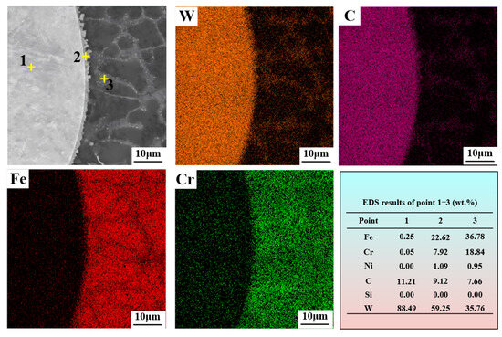
Figure 9 presents a WC particle featuring partially molten edges, along with its EDS scanning profiles and elemental compositions at Positions 1–3. Despite slight melting at the periphery, the WC particle maintains its spherical morphology. The EDS results clearly reveal the distribution of W, C, Fe, and Cr. Point 1 is dominated by W (88.49 at.%) and C (11.21 at.%) with negligible amounts of other elements, confirming that it is a WC particle. Point 2 is the melted layer of the WC particle, where W (59.25%) and C (9.12%) are rich, and Cr (7.92%) and Fe (22.62%) infiltrate into this molten zone. Point 3 is the surrounding area where W and C atoms are released into the molten pool, and Fe (38.42%), Cr (18.84%), W (35.76%), and C (7.66%) composite phases are formed.
Figure 9.
EDS scanning results of the edge-melted WC particle.
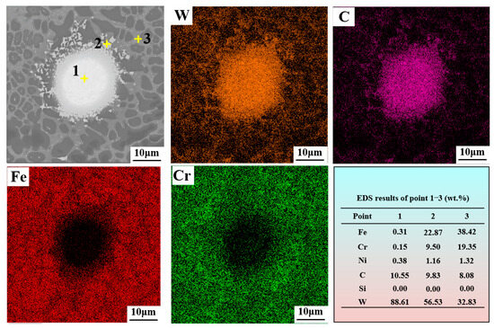
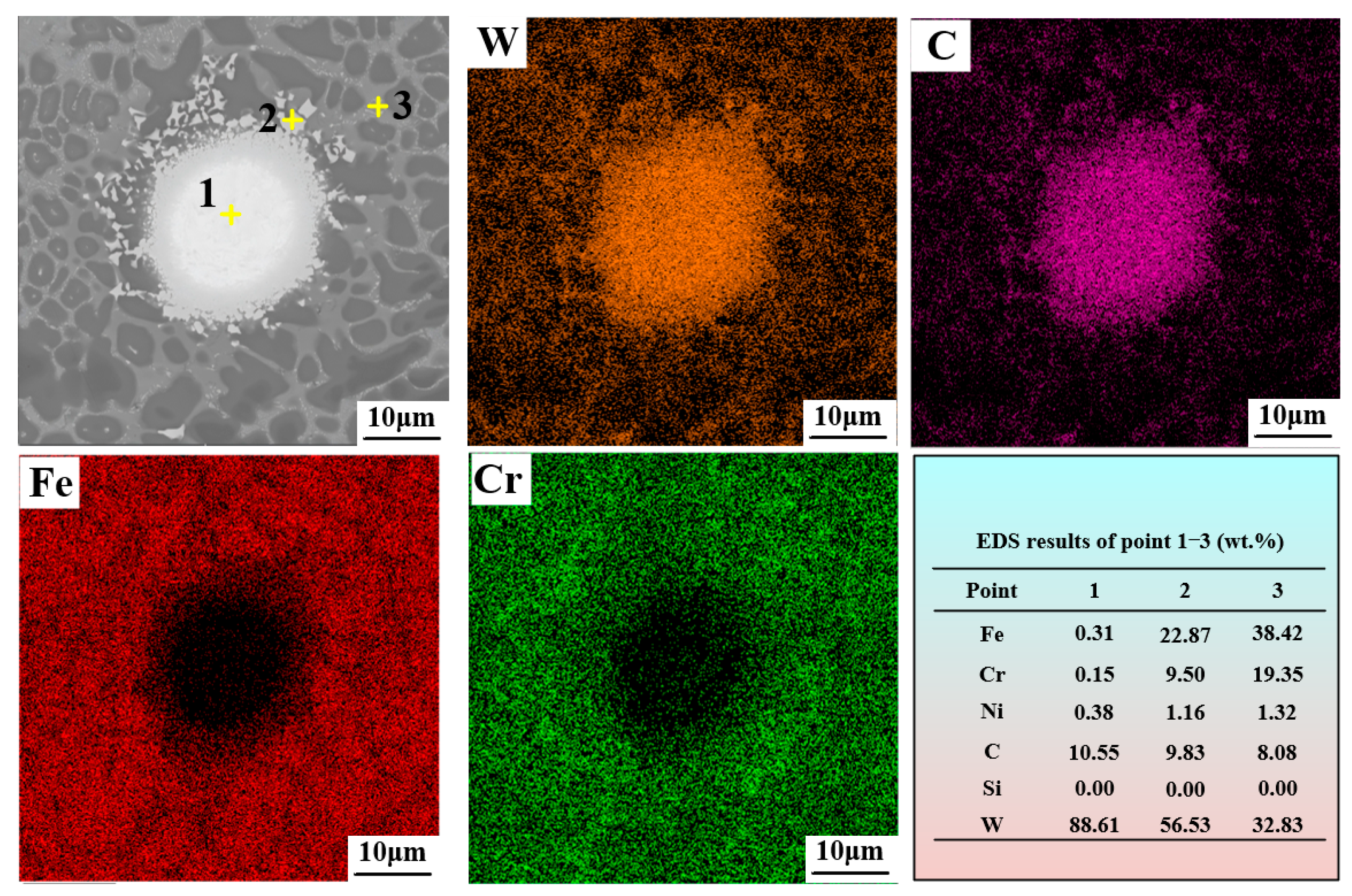
Figure 10 illustrates a partially melted WC particle and EDS scanning results. The element distribution at positions 1–3 is also scanned. Under the coupling effect of high temperature and external force in the molten pool, the outer surface of the WC particle undergoes severe melting and decomposition. Numerous irregular debris flow into the surrounding coating. EDS analysis shows that point 1 is enriched with W (88.61%) and C (10.55%) elements. Point 2 contains not only W (59.25%) and C (9.12%) but also Fe (22.87%), Cr (9.5%), and Ni (1.16%), which is a mixture of melted WC and Fe-based alloys. And at point 3 away from the WC particle, the content of Fe (38.42%) and Cr (19.36%) significantly increases, while the content of W (32.83%) and C (8.08%) elements decreases.
Figure 10.
EDS patterns of the partially melted WC particle.
3.3.2. Phase Composition
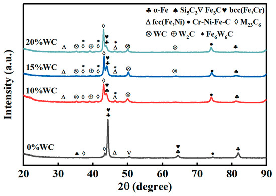
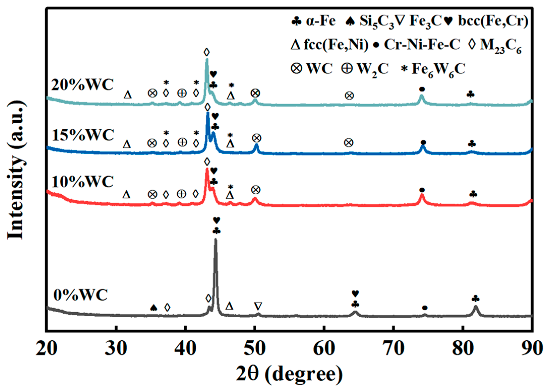
X-ray diffraction analysis was conducted on the central region of the four types of composite coatings, as shown in Figure 11. It is illustrated that the 0% WC/Fe-based coating is composed of α-Fe, Si5C3, Fe3C, M23C6 (M = Fe, Cr), bcc (Fe, Cr), fcc (Fe, Ni), and Cr-Ni-Fe-C. Among them, α-Fe is the matrix phase, and Si5C3, Fe3C, and M23C6 (M = Fe, Cr) are typical hard carbides, which have the function of dispersion strengthening and can hinder dislocation motion. After adding the WC particles to the Fe-based coating, the number of diffraction peaks increased, and new phases such as WC, Fe6W6C, and W2C were generated due to the decomposition of WC particles, as shown in Figure 9 and Figure 10. The W and C atoms diffused into the molten pool. W2C is generated by the “decarburization” reaction of WC (WC → W2C + C), which has a higher melting point and hardness than WC. W2C can combine with WC to form eutectic mixtures, which is beneficial for refining the microstructure of the composite coating. At the same time, the in-situ formation of Fe6W6C and M23C6 occurs in the molten pool. There exist reactions of 6Fe + 3W2C → Fe6W6C + 5W and 23M + 6C → M23C6 (M = Fe, Cr). The higher the WC content, the more Fe6W6C and M23C6 are formed.
Figure 11.
XRD spectrum of WC/Fe-based composite coatings.
In addition, it can be seen from Figure 11 that when the WC content increases, the main diffraction peak shifts slightly to the left. According to the Bragg equation [36], there is 2dsinθ = nλ, with d the interplanar spacing, θ the diffraction angle, n an integer multiple of the wavelength, and λ the wavelength of the incident wave. Therefore, increasing d leads to a decrease in θ. After the WC particles partially melt, many W atoms penetrate into the α-Fe lattice. The interplanar spacing increases because the radius of W atoms (139 pm) is bigger than that of Fe atoms (124 pm), and thus the diffraction angle decreases. Ultimately, the diffraction peak shifts toward lower angles.
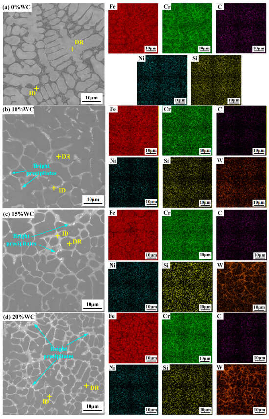
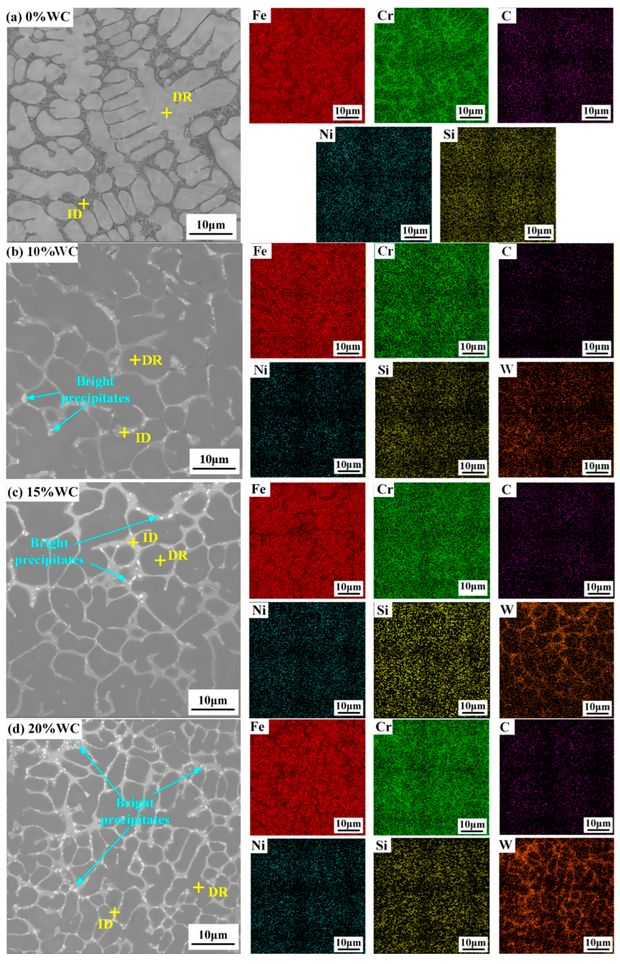
To further investigate the effects of WC contents on the phase and element distribution of the microstructure, the EDS surface scanning of the local regions of the WC/Fe-based composite coatings was conducted, as shown in Figure 12. Moreover, the element distribution within the dendrite region (DR) and inter-dendrite region (ID) were also detected, as given in Table 2.
Figure 12.
SEM image and EDS scanning of local coatings with different WC contents.
Table 2.
Element distribution in DR and ID of coatings with different WC contents (wt.%).
From Figure 12a and Table 2, it can be seen that the Fe element is mainly distributed in DR, while the Cr element is enriched in ID of the WC-free Fe-based coating. The other elements, such as C, Ni, and Si, are distributed uniformly. In addition, due to the mixing enthalpy of Cr and C being much lower than that of Cr and Fe, Cr prefer to combine with C to form M23C6 carbide. Therefore, it is speculated that the M23C6 carbide phase is mainly distributed in ID.
From Figure 12b and Table 2, it can be seen that besides other elements mentioned above, there is an additional W element in the coating with 10%WC. Due to the decomposition of WC particles. W and C spread into the molten pool, and W-containing carbides such as Fe6W6C and W2C are formed. The Cr element in DR increases compared to the WC-free Fe-based coating, indicating an increase of Cr in the α-Fe matrix. The W element content in ID is higher than that in DR, and the Cr content increases while the Fe content decreases, indicating that the interdendritic spacing contains M23C6 and W2C, accompanied by a certain amount of Fe6W6C, etc.
For the 15% and 20% WC/Fe-based composite coatings shown in Figure 12c,d, the distribution of Fe, Cr, C, Ni, and Si is similar to that in the 10% WC coating. Nevertheless, obvious segregation of the W element can be clearly identified. Due to atomic-level strain effects, the bcc-structure of α-Fe also contains a certain amount of W inside. The participation of W with a larger atomic radius in α-Fe will form a supersaturated solid solution, resulting in severe lattice distortion in α-Fe [37]. This will lead to an increase in energy. To maintain the lowest Helmholtz free energy, W atoms eventually accumulate in ID with an irregular atomic arrangement, thereby exhibiting a segregation phenomenon.
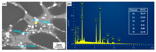
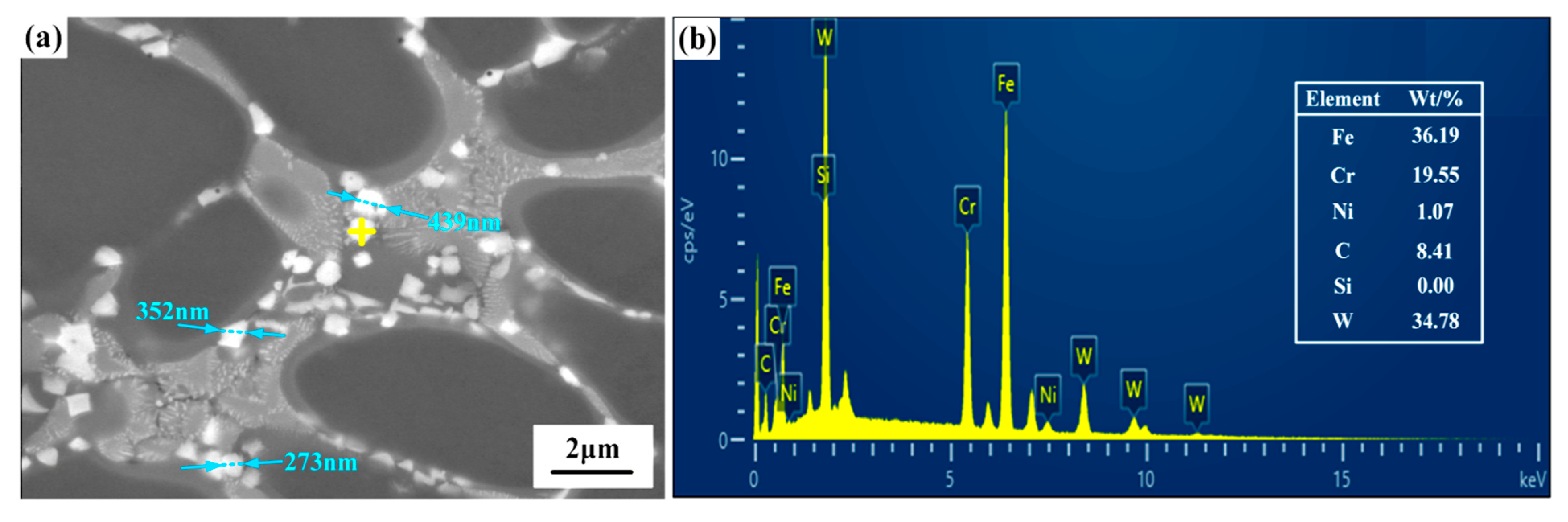
Furthermore, from Figure 12b–d, it can be observed that there are scattered bright precipitates in the ID of the microstructure. As the amount of WC added increases, the bright precipitates increase and gather at the grain boundaries. To make clear the composition of the precipitate, the agglomeration ID was locally enlarged, and EDS point scanning was performed, as shown in Figure 13. It is illustrated that the bright precipitates have irregular shapes, with a size range of approximately 200nm to 400 nm. The precipitate is mainly composed of W, Fe, and Cr elements, with a small amount of C. Fe6W6C is a metastable eta (η) phase that only forms within the liquid eutectic zone of the Fe–W–C system [38]. M23C6 is a low-temperature grain-boundary precipitate generated during cooling, with particle sizes ranging from 200 to 400 nm [39]. Accordingly, combined with XRD analysis, it can be inferred that the precipitates consist of hard phases, including Fe6W6C, M23C6, and W2C.
Figure 13.
(a) Magnified image of ID structure and (b) EDS of the white precipitate phase.
3.4. Microhardness
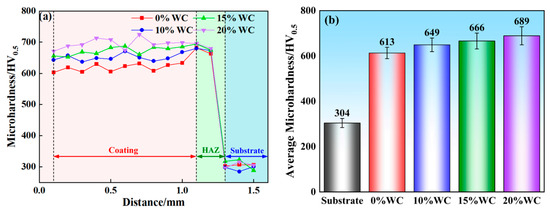
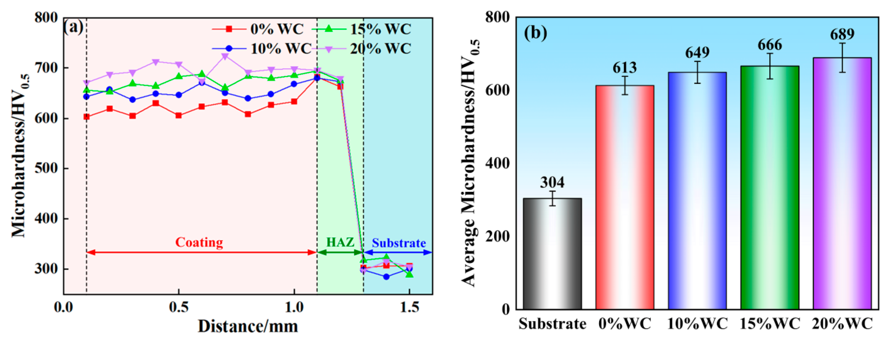
Figure 14 shows the microhardness change curves of each WC/Fe-based composite coating and its average microhardness. It can be seen that microhardness increases with increasing WC content. When the WC mass fraction is 0%, 10%, 15%, and 20%, the average hardness of the coatings is 613 HV0.5, 649 HV0.5, 666 HV0.5, and 689 HV0.5, respectively, while that of the HT250 substrate is only 304 HV0.5. The hardness of the composite coatings is more than twice that of the HT250 substrate. Compared with the WC-free Fe-based coating, the microhardness of WC/Fe-based composite coatings with 10%, 15%, and 20%WC is improved by 5.9%, 8.6%, and 12.4%, respectively. This is because a higher WC content in composite coatings raises the volume fraction of hard phases such as W2C, M23C6, and Fe6W6C, and thus increases the hardness of the composite coatings.
Figure 14.
Microhardness test results: (a) cross-section hardness profiles; (b) average hardness values.
3.5. Tribology Characteristics
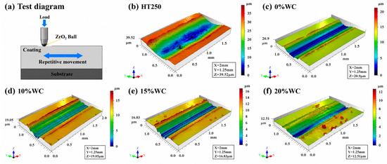
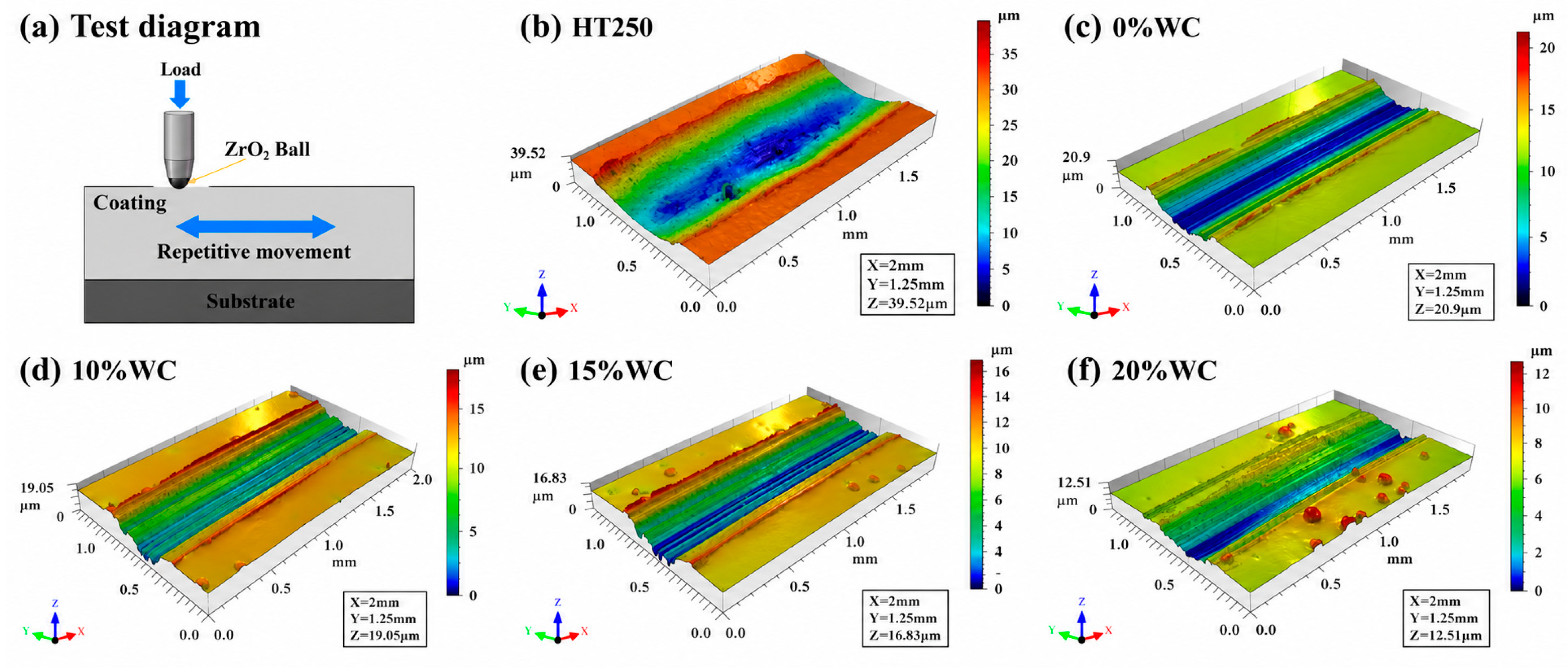
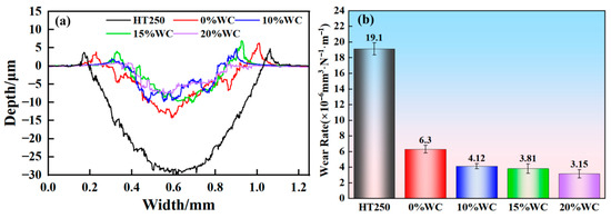
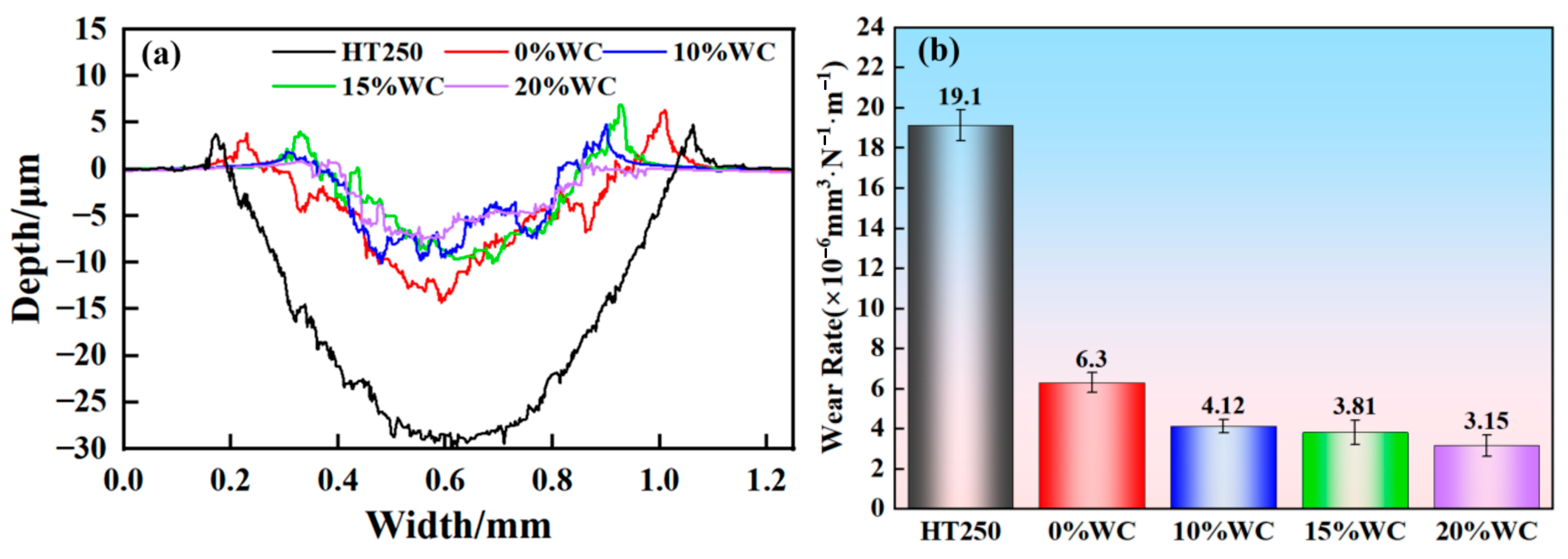
Figure 15 illustrates the three-dimensional (3D) wear scars for all specimens, and Figure 16 gives their cross-section profiles and the wear rates calculated by Equation (1). Evidently, the HT250 substrate exhibits the largest wear depth (30.03 μm) and wear width (0.89 mm) owing to its low hardness. Relatively, the wear amounts of the WC/Fe-based composite coatings are significantly reduced. The wear depth and width of the WC-free Fe-based coating are 14.21 μm and 0.77 mm, respectively. Incorporation of WC particles further lowers the wear loss of the composite coatings. When the WC content reaches 20%, the wear depth and width of the composite coating are only 8.11 μm and 0.54 mm, respectively. The wear rate of the HT250 substrate is 19.1 × 10⁻⁶ mm3∙N−1∙m−1, while the value for the 20% WC/Fe-based composite coating is 3.15 × 10⁻⁶ mm3∙N−1∙m−1. Accordingly, the wear resistance of the composite coating is improved by nearly six times relative to the HT250 substrate. Increasing the WC fraction facilitates the improvement of the wear resistance of the coatings.
Figure 15.
3D wear track morphology of different specimens.
Figure 16.
Wear test results of specimens: (a) cross-section profiles; (b) wear rates.
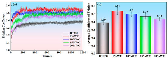
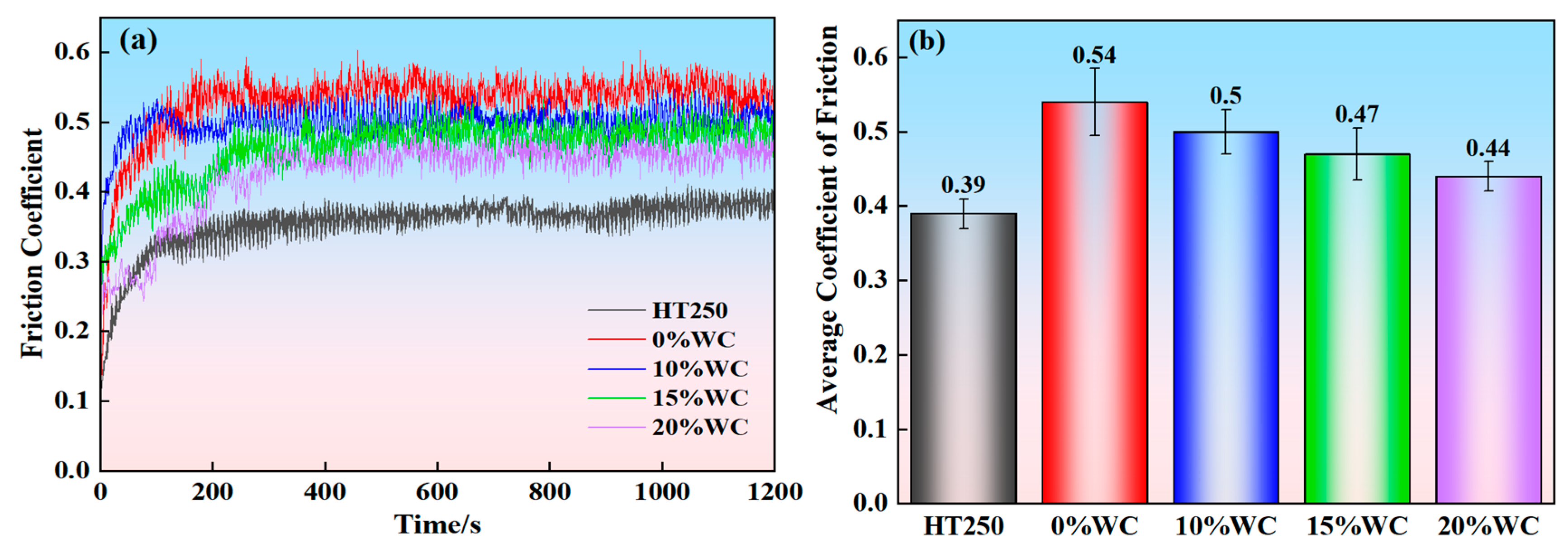
Figure 17 illustrates the CoFs of the HT250 substrate and the WC/Fe-based composite coatings. For all samples, the friction curve undergoes a running-in stage for about 200 s and then a stable stage, as shown in Figure 16a. The data in the steady state from 200 s to 1200 s of each test are used to calculate an average CoF. As shown in Figure 17b, under the same test conditions, the CoF of the 0% WC/Fe-based coating is the biggest (0.54), and those of the composite coatings with 10%, 15%, and 20% WC are 0.5, 0.47, and 0.44, respectively. Enhancing the WC content in the coating can reduce the friction coefficient by about 7.4%, 12.9%, and 18.5%, respectively. It should be pointed out that the average CoF of the HT250 substrate has a lower friction coefficient (0.39) than the WC/Fe-based composite coatings. This may be the self-lubricating effect of the graphite contained in cast iron itself. Although the CoFs of the composite coatings are higher than that of the HT250 substrate to some extent, their hardness and wear resistance are heavily enhanced, especially for the 20%WC composite coating.
Figure 17.
Friction test results of specimens: (a) friction coefficient curves; (b) average friction coefficients.
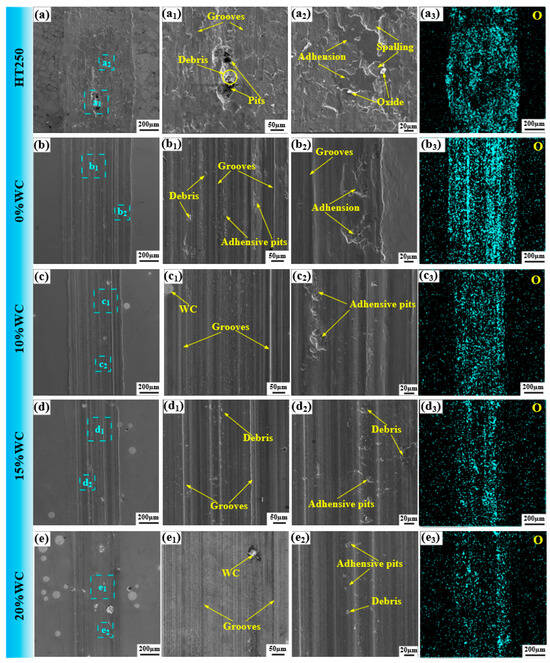
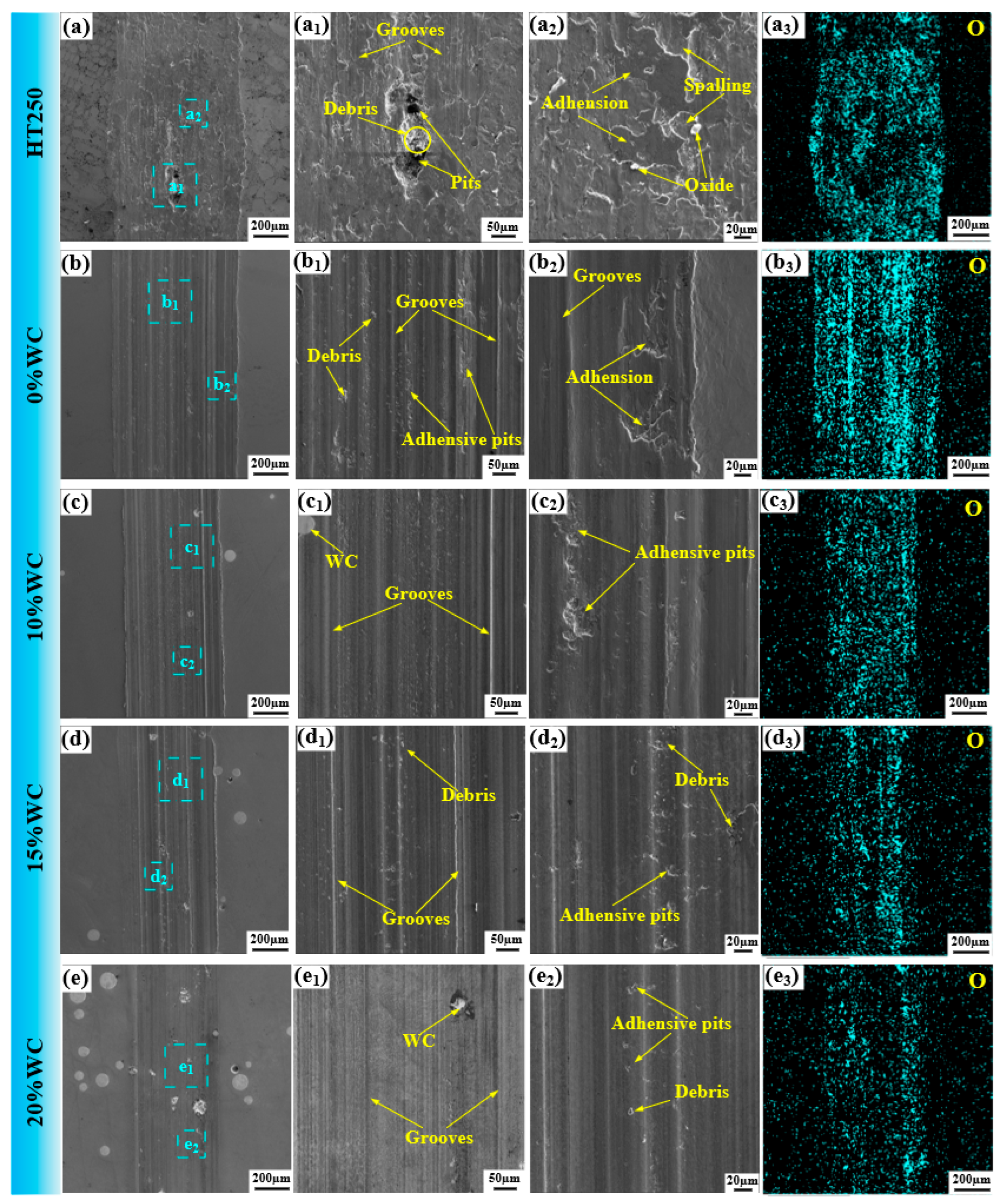
Figure 18 shows the SEM images and the oxygen element detection results of the worn surface. As observed, the HT250 substrate suffers severe wear. Obvious plastic deformation, intensive adhesion, spalling, and pits can be detected on its worn surface. According to the EDS mapping in Figure 18(a3), it is found that serious oxidative wear occurs in the process of friction.
Figure 18.
SEM image and EDS scanning of wear surfaces for different specimens. (a–a3) HT250; (b–b3) 0% WC; (c–c3) 10% WC; (d–d3) 15% WC; (e–e3) 20% WC.
In contrast to the HT250 substrate, the 0% WC/Fe-based coating exhibits a much smoother worn morphology, as illustrated in Figure 18(b–b2). Adhesion and spalling defects are drastically suppressed, though prominent abrasive grooves remain visible on the contact surface. This improvement originates from abundant hard carbide phases (M23C6, Si5C3, and Fe3C) distributed within the Fe-based matrix. When the grinding ball moves reciprocally on the coating surface, these carbides cause strain hardening. Nevertheless, the EDS spectrum in Figure 18(b3) reveals that surface oxidation remains a significant oxidation behavior for this coating.
Figure 18(c–c2) to Figure 18(e–e2) illustrate the worn morphologies of WC/Fe-based composite coatings reinforced with 10%, 15%, and 20% WC ceramic particles, respectively. The wear damage is evidently mitigated with increasing WC content. In particular, the 20% WC coating exhibits the shallowest abrasive grooves, alongside minimal pits and wear debris. Such superior wear resistance stems from the embedded WC ceramic particles. As discussed earlier, WC incorporation promotes the precipitation of abundant hard carbides (W2C, M23C6, Fe6W6C, etc.), which simultaneously refine matrix grains and exert dispersion-strengthening effects on the composite coating. Unmelted WC particles act as physical barriers during reciprocating contact with the counterpart ball, disrupting friction propagation and confining plastic deformation within a narrower region. Meanwhile, the EDS maps in Figure 18(c3,d3,e3) demonstrate that surface oxidation is substantially suppressed for WC-reinforced coatings.
3.6. Corrosion Characteristics
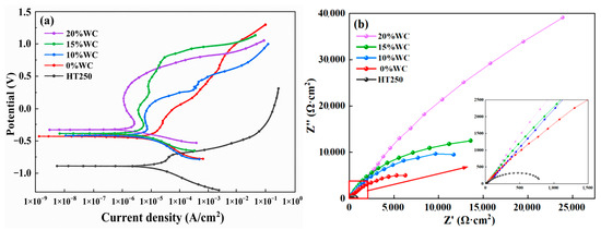
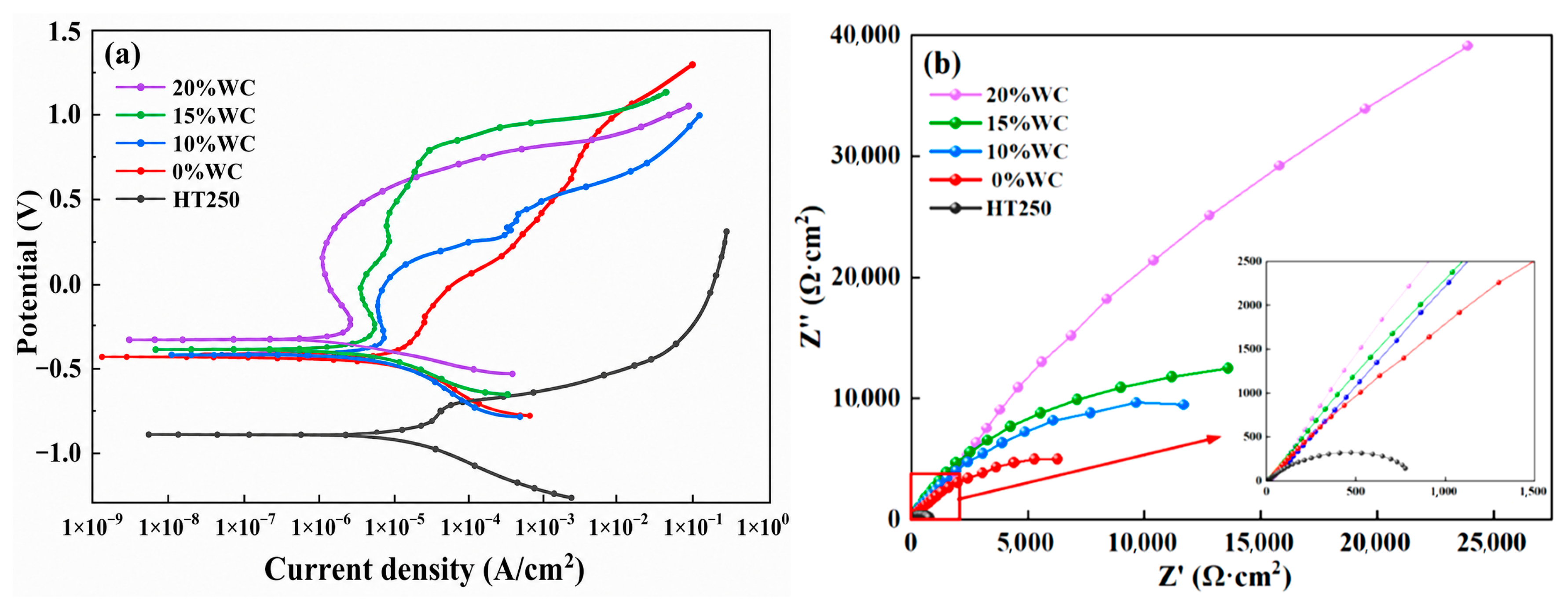
Figure 19 displays the potentiodynamic polarization curves and electrochemical impedance Nyquist plots of the HT250 substrate and WC/Fe-based composite coatings with varying WC contents. The electrochemical performance parameters of all specimens were obtained via the Tafel extrapolation method and equivalent circuit fitting, as listed in Table 3. Combining the data from Table 3 and Figure 19a, all WC/Fe composite coatings exhibit a lower corrosion current density (Icorr) than the HT250 substrate, which indicates a slower corrosion rate. Meanwhile, the coatings possess a more positive corrosion potential (Ecorr) compared with the substrate, revealing a weaker tendency toward electrochemical corrosion. As WC content rises, the Icorr of coatings decreases while Ecorr shifts positively, demonstrating improved corrosion resistance. Among them, the 20% WC/Fe-based composite coating has the highest corrosion resistance with the minimum Icorr of 1.5451 × 10⁻⁶ A/cm2 and the most positive Ecorr of −0.28863 V. According to the EIS parameters extracted from Figure 19b, all WC/Fe composite coatings show a smaller constant phase element value (CPE) of the passivation film and a higher polarization resistance (Rp), verifying that the coating effectively higher corrosion resistance than the substrate. The 20% WC/Fe-based composite coating achieves the smallest CPE of 1.7 × 10⁻⁴ S·sn·cm−2 and the maximum Rp of 63,165 Ω·cm2.
Figure 19.
Electrochemical test results of specimens: (a) Polarization curve graph; (b) Nyquist plot of impedance spectrum.
Table 3.
Electrochemical parameter results of different specimens.
4. Conclusions
(1) WC/Fe-based composite coatings with varying WC contents were deposited onto HT250 substrates via laser cladding technology. The resulting coatings exhibited excellent forming quality, free from cracks or porosity. Along the cross-section from the coating-substrate interface to the top surface, the microstructure evolved from fine planar crystals to columnar crystals, dendrites, and finally equiaxed crystals, indicating strong metallurgical bonding with the substrate.
(2) During laser cladding, WC particles experience varying degrees of melting, including marginal melting and partial melting. As the WC content increased from 0% to 20%, the grain refinement effect induced by WC particles becomes increasingly pronounced. Statistically, the average grain size of the coating decreased from 6.33 μm to 4.92 μm, and the secondary dendrite arm spacing was reduced from 4.05 μm to 2.85 μm. The WC/Fe-based composite coatings consist of an α-Fe matrix and carbide reinforcing phases, including M23C6 (M = Fe, Cr), Fe6W6C, WC, and W2C, which provide effective dispersion strengthening.
(3) The microhardness of HT250 substrate is 304 HV0.5, while the WC/Fe-based composite coatings containing 10%, 15%, and 20%WC exhibit microhardness values of 649HV0.5, 666HV0.5, and 689 HV0.5, respectively. The hardness of the WC/Fe-based composite coating is more than twice that of the HT250 substrate. The enhanced hardness mainly stems from WC-induced strengthening effects, including grain refinement, solid-solution strengthening in the α-Fe lattice, and the generation of hard in-situ carbides.
(4) As the WC content increases, both the wear and corrosion resistance of the composite coatings are enhanced. By comparison, the wear rates of the WC/Fe-based composite coatings with 10%, 15%, and 20% WC are only 22%, 20%, and 16% of those of the HT250 substrate, respectively. While the average CoFs of the WC/Fe-based composite coatings with 10%, 15%, and 20% WC are 0.50, 0.47, and 0.44, respectively, which are slightly higher than that of the HT250 substrate (0.39). Among all groups, the 20% WC/Fe-based composite coating exhibits the CoF value closest to the substrate. Furthermore, the 20% WC/Fe-based composite coating possesses the densest passivation film on its surface, which hinders the penetration of corrosive media and suppresses propagation of electrochemical corrosion, thereby delivering superior corrosion resistance. Overall, the 20% WC/Fe-based composite coating possesses the optimal comprehensive performance.
Author Contributions
L.L.: Conceptualization, methodology, writing—original draft. J.W.: investigation, methodology, data curation. Y.Q.: formal analysis. B.G.: data curation, visualization. Q.L.: review and editing. Q.X.: validation. All authors have read and agreed to the published version of the manuscript.
Funding
This research was funded by the National Natural Science Foundation of China (Grant No. 42472381) and the Key Science and Technology Program of Shaanxi Province (2025CY-YBXM-089).
Data Availability Statement
Data will be made available on request.
Conflicts of Interest
The authors declare no conflicts of interest.
References
- Yong, Z.; Pan, L.; Yang, G.; Zhang, Q.; Yao, J. Research on the Origin of Pores in HT250 Cast Iron Fabricated by Laser Remelt. Int. J. Met. 2025, 19, 3392–3404. [Google Scholar] [CrossRef] [Scilit]
- Ahmadkhaniha, D.; Zanella, C.; Belov, I.; Matsushita, T. Study of the process parameters influence on crack formation in laser alloying of grey cast iron. Opt. Laser Technol. 2024, 179, 111373. [Google Scholar] [CrossRef] [Scilit]
- Lu, S.; Zhou, J.; Wang, L.; Liang, J. Influence of MoSi2 on the microstructure and elevated-temperature wear properties of Inconel 718 coating fabricated by laser cladding. Surf. Coat. Technol. 2021, 424, 127665. [Google Scholar] [CrossRef] [Scilit]
- Chen, Z.; Zhang, Y.; Chi, Y.; Gou, J.; Lin, C. Research on morphology, porosity, mechanical properties of 7075 aluminum alloy repaired by arc welding and laser shock forging. Heliyon 2023, 9, 22791. [Google Scholar] [CrossRef] [Scilit] [PubMed]
- Cheng, B.; Mao, C.; Zhang, M.; Wu, D.; Jiang, H.; Ma, G. Comparative study on microstructure and properties of laser welding and argon arc welding Hastelloy C-276/SS304 with filler wire. Opt. Laser Technol. 2023, 164, 109565. [Google Scholar] [CrossRef] [Scilit]
- Latka, L.; Pawlowski, L.; Winnicki, M.; Sokolowski, P.; Małachowska, A.; Kozerski, S. Review of functionally graded thermal sprayed coatings. Appl. Sci. 2020, 10, 5153. [Google Scholar] [CrossRef] [Scilit]
- Zheng, Y.; Wang, D.; Zheng, W.; Feng, D.; Wang, W.; Yang, J. Fabrication of high-quality aluminum alloy coating on the surface of CoCrFeNi high-entropy alloy via laser cladding. Surf. Interfaces 2025, 73, 107543. [Google Scholar] [CrossRef] [Scilit]
- Huang, C.; Fang, S.; Luo, J.; Zeng, H.; Liu, H.; Huang, H.; Yang, L.; Wang, H.; Chen, Z. Pre-corrosion of laser-cladding-prepared high-entropy alloy coating for alkaline oxygen evolution reaction. Electrochim. Acta 2025, 538, 147001. [Google Scholar] [CrossRef] [Scilit]
- Zhang, X.; Li, R.; Huang, L.; Amar, A.; Wu, C.; Le, G.; Liu, X.; Guan, D.; Yang, G.; Li, J. Influence of in-situ and ex-situ precipitations on microstructure and mechanical properties of additive manufacturing CoCrFeMnNi high-entropy alloys. Vacuum 2021, 187, 110111. [Google Scholar] [CrossRef] [Scilit]
- Ouyang, C.; Deng, R.; Wei, R.; Li, H.; Wang, R.; Zhao, C. Methods and techniques for enhancing wear resistance of laser cladding coatings: A comprehensive review. J. Manuf. Process. 2025, 152, 1123–1149. [Google Scholar] [CrossRef] [Scilit]
- Manoj, A.; Verma, P.C.; Narala, S.K.R.; Saravanan, P.; Tiwari, S.K.; Joshi, S. High-temperature tribological evaluation of cobalt-based laser cladded disc for automotive brake systems. Ceram. Int. 2024, 50, 54458–54472. [Google Scholar] [CrossRef] [Scilit]
- Xv, Y.; Sun, Y.; Zhang, Y. Prediction method for high-speed laser cladding coating quality based on random forest and AdaBoost regression analysis. Materials 2024, 17, 1266. [Google Scholar] [CrossRef] [Scilit] [PubMed]
- Dhiraj, R.; Ranjan, M.S.; Bipul, D. Characterisation of laser-cladded 410 stainless steel for in situ repair of turbine blade. Surf. Eng. 2024, 40, 515–526. [Google Scholar] [CrossRef] [Scilit]
- Liu, L.; Yang, F.; Wang, J.; Wang, S.; Guo, B. Remanufacturing oriented statistical optimization and performance analysis of laser cladding Ni60 coating on 316L piston rods. J. Laser Appl. 2025, 37, 032025. [Google Scholar] [CrossRef] [Scilit]
- Ding, H.; Mu, X.; Zhu, Y.; Yang, W.; Xiao, Q.; Wang, W. Effect of laser claddings of Fe-based alloy powder with different concentrations of WS2 on the mechanical and tribological properties of railway wheel. Wear 2022, 488, 204174. [Google Scholar] [CrossRef] [Scilit]
- Cui, G.; Han, B.; Zhao, J.; Li, M. Comparative study on tribological properties of the sulfurizing layers on Fe, Ni and Co based laser cladding coatings. Tribol. Int. 2019, 134, 36–49. [Google Scholar] [CrossRef] [Scilit]
- Liu, Y.; Ding, Y.; Yang, L.; Sun, R.; Zhang, T.; Yang, X. Research and progress of laser cladding on engineering alloys: A review. J. Manuf. Process. 2021, 66, 341–363. [Google Scholar] [CrossRef] [Scilit]
- Xie, L.; Wang, Y. Microstructure and Mechanical Properties of Fe-Based Alloy Coatings Fabricated by Laser Cladding. Mater. Sci. 2023, 29, 456–462. [Google Scholar] [CrossRef] [Scilit]
- Wang, H.; Zhang, X.; Cao, C.; Ren, L.; Li, J. Research on the influence of laser power on the microstructure and performance of Fe-based coating. J. Therm. Spray Technol. 2025, 34, 316–336. [Google Scholar] [CrossRef] [Scilit]
- Zhang, B.; He, B.; Wang, H. Investigation on laser cladding Fe-based gradient coatings with hierarchical enhanced wear resistance on U75V railway steel. Wear 2024, 552, 205444. [Google Scholar] [CrossRef] [Scilit]
- Liu, J.; Li, Y.; He, P.; Tan, N.; Li, Q.; Zhang, G.; Lu, B. Microstructure and properties of ZrB2-SiC continuous gradient coating prepared by high speed laser cladding. Tribol. Int. 2022, 173, 107645. [Google Scholar] [CrossRef] [Scilit]
- Yang, C.; Zeng, C.; Xu, P.; Song, W.; Liu, J.; Zhang, Y.; Xiong, J.; Li, Q.; Su, Z.; Huang, Q. Effect of non-static pre-oxidation treatment on the cyclic ablation behavior of SiC-ZrC/SiC multilayer coated graphite. Ceram. Int. 2024, 50, 51218–51228. [Google Scholar] [CrossRef] [Scilit]
- Chen, S.; Su, Y.; Sun, Q.; Fan, H.; Song, J.; Hu, L.; Zhang, Y. Strong, tough and high temperature self-lubricated fibrous monolithic ceramic in Al2O3/Cr2O3 system. Tribol. Int. 2022, 172, 107646. [Google Scholar] [CrossRef] [Scilit]
- Zhuang, D.; Tao, W.; Du, B.; Zhang, S.; Lian, X.; Wang, F. Microstructure and properties of TiC-enhanced CrMnFeCoNi high-entropy alloy coatings prepared by laser cladding. Tribol. Int. 2023, 180, 108246. [Google Scholar] [CrossRef] [Scilit]
- Hu, Y.; Wang, Z.; Pang, M. Effect of WC content on laser cladding Ni-based coating on the surface of stainless steel. Mater. Today Commun. 2022, 31, 103357. [Google Scholar] [CrossRef] [Scilit]
- Yue, K.; Wang, L.; Xu, Z.; Cheng, C.; Wang, Y.; Fan, Y.; Xu, J.; Wang, Z.; Chen, Z. Effect of WC content on the microstructure and wear resistance of laser cladding AlCoCrFeNiTi0.5 high-entropy alloy coatings. Ceram. Int. 2024, 50, 41515–41526. [Google Scholar] [CrossRef] [Scilit]
- Ji, F.; Luo, C.; Pang, M.; Qian, Z. Effect of WC particle size on the microstructural evolution and tribological properties of laser cladding Ti-bearing Co-based WC reinforced coating. Surf. Coat. Technol. 2024, 494, 131394. [Google Scholar] [CrossRef] [Scilit]
- Lu, J.; Cao, J.; Lu, H.; Luo, K. Wear properties and microstructural analyses of Fe-based coatings with various WC contents on H13 die steel by laser cladding. Surf. Coat. Technol. 2019, 369, 228–237. [Google Scholar] [CrossRef] [Scilit]
- Cao, Y.; Yin, Z.; Zhan, Y.; Wang, S.; Wen, D.; Wang, G.; Xia, D.; Li, Y.; Hou, D. Optimisation and wear performance analysis of laser-cladded WC-Fe-based coating. Insight-Non-Destr. Test. Cond. Monit. 2024, 66, 153–158. [Google Scholar] [CrossRef] [Scilit]
- Wei, A.; Tang, Y.; Tong, T.; Wan, F.; Yang, S.; Wang, K. Effect of WC on microstructure and wear resistance of Fe-based coating fabricated by laser cladding. Coatings 2022, 12, 1209. [Google Scholar] [CrossRef] [Scilit]
- Bartkowski, D.; Bartkowska, A.; Jurči, P. Laser cladding process of Fe/WC metal matrix composite coatings on low carbon steel using Yb: YAG disk laser. Opt. Laser Technol. 2021, 136, 106784. [Google Scholar] [CrossRef] [Scilit]
- Li, J.; Liu, L.; Wang, J.; Wang, S.; Han, F. The porosity suppression process of laser cladding nickel-based coatings with 57%WC content on P550 non-magnetic steel. Mater. Sci. Eng. Powder 2025, 30, 490–501. [Google Scholar] [CrossRef]
- Lin, G.; Cai, Z.; Lu, B.; Gu, L.; Wang, Y.; Yan, X.; Qiu, H.; Guo, J.; Dong, Z.; Li, F. Enhanced wear resistance of laser cladded WC-Ni composite coatings by picosecond laser surface texturing. Tribol. Int. 2025, 204, 110517. [Google Scholar] [CrossRef] [Scilit]
- Gao, Z. Fully automated grain size measurement method based on cascaded dual-stage grain boundary analysis framework. Iron Steel 2025, 60, 167–174. [Google Scholar] [CrossRef]
- Bellé Roberto, M.; Sherstneva, A.; Hauser, M.; Wendler, M.; Volkova, O. Correlation between particle size, secondary dendrite arm spacing, and local cooling rate in gas-atomized stainless steel powders for additive manufacturing. Powder Technol. 2025, 461, 121096. [Google Scholar] [CrossRef] [Scilit]
- Zhou, M.; Zhao, J.; Chen, S.; Wang, Q.; Wang, X.; Liu, C. High-Pressure Luminescence Properties of Eu2+-Doped Si3N4 Nanowires and Their Application in Optical Pressure Sensing. Acta Phys. Sin. 2025, 75, 265–273. [Google Scholar] [CrossRef] [Scilit]
- Hui, Z.; Zou, Y.; Zou, Z.; Wu, D. Microstructure and properties of Fe-based composite coating by laser cladding Fe-Ti-V-Cr-C-CeO2 powder. Opt. Laser Technol. 2015, 65, 119–125. [Google Scholar] [CrossRef] [Scilit]
- Zhu, W.T.; Cai, Q.S.; Wang, J.N.; Liu, W.S.; Ma, Y.Z. Microstructure and mechanical properties of 90W-7Ni-3Fe/30CrMnSiNi2A structural composite materials prepared by powder metallurgy co-sintering. Chin. J. Nonferrous Met. 2021, 31, 1737–1746. [Google Scholar] [CrossRef]
- Li, J.; Zhu, Z.; Peng, Y.; Shen, G.; Li, X. Friction and Wear Behavior of In-Situ Synthesized M23C6-WC Dual-Carbides Synergistically Reinforced Laser Cladding Coatings. Tribology 2021, 41, 843–857. [Google Scholar] [CrossRef]

Disclaimer/Publisher’s Note: The statements, opinions and data contained in all publications are solely those of the individual author(s) and contributor(s) and not of MDPI and/or the editor(s). MDPI and/or the editor(s) disclaim responsibility for any injury to people or property resulting from any ideas, methods, instructions or products referred to in the content. |
© 2026 by the authors. Licensee MDPI, Basel, Switzerland. This article is an open access article distributed under the terms and conditions of the Creative Commons Attribution (CC BY) license.