


Abstract
Accurate thermal management is crucial for ensuring the safety, longevity, and performance of lithium-ion batteries, especially in compact embedded systems like USB chargers, power banks, and IoT nodes. Despite extensive research on predictive thermal models and intelligent control frameworks, their implementation in resource-constrained microcontroller-class devices has been limited. Existing strategies in the literature, such as threshold-based or PID logic, cloud-enabled analytics, machine learning models, and observer-based estimators, are often reactive, computationally intensive, or dependent on external infrastructure, making them unsuitable for low-power, standalone applications. This study introduces a novel Scalable Embedded Thermal Intelligence architecture designed for real-time battery thermal regulation in locally executable, without cloud dependency, low-cost platforms. Unlike conventional methods, the proposed system operates entirely on-device using closed-form models implemented on an ESP32 microcontroller. It combines two synergistic algorithms: a static preemptive model that calculates a safe C-rate at startup based solely on ambient and initial battery temperature, and a dynamic disturbance-aware model that monitors temperature rise per SOC step and adjusts airflow or current adaptively without requiring high memory, floating-point units, or supervisory control. The architecture achieves sub-second response times, <7% RAM, and <25% Flash usage, and does not need cloud connectivity, simulation backend, or complex thermal-management infrastructures such as liquid cooling circuits, phase-change systems, or cloud-supervised architectures. The significant contribution of this work is not the introduction of a new electrochemical–thermal formulation, but the effective integration and application of previously validated closed-form thermal predictors on low-cost microcontroller-class hardware, designed for anticipatory battery thermal regulation while adhering to strict computational limitations. Compared to traditional battery thermal management systems using PCM, liquid-cooling circuits, or cloud-based predictive estimators, the proposed approach eliminates the need for complex thermal hardware, fluidic systems, external computing infrastructure and resource-efficient edge operation. This makes the system suitable for deployment in real-world embedded applications like USB-C smart charging cables, compact IoT power banks, and portable medical devices, where form factors, energy efficiency, and cost are critical. The proposed SETI framework offers a firmware-integrated architecture and a firmware-integrated solution that provides a lightweight embedded alternative for predictive thermal regulation for distributed energy systems and miniaturized electronics.
1. Introduction
Temperature prediction and control are crucial for ensuring the safety, efficiency, and reliability of modern engineering systems [1,2]. Thermal prediction helps in making informed design decisions, mitigating risks, and controlling systems in real-time across various industrial and energy-related applications [3,4]. Different thermal modeling approaches, including analytical [5], semi-analytical [6], and numerical techniques [7] like the Finite Element Method, are used based on the complexity and scale of the system. Lithium-ion batteries (LIBs) are highly sensitive to temperature variations due to their high energy density and widespread use in consumer electronics, electric vehicles, and energy storage systems. Operating outside the optimal temperature range accelerates degradation and reduces battery capacity and power capability [8,9]. Therefore, ensuring battery safety and thermal reliability is crucial for designing high-performance power delivery systems. Advancements in IoT and embedded computing have enabled the development of scalable, edge-level intelligence for energy-efficient control. IoT frameworks support decentralized decision-making and real-time data acquisition, improving energy management in smart buildings [10], microgrids [11,12], and distributed energy networks [13]. Implementing digital thermal intelligence in charging interfaces [14] allows for dynamic adjustment of charging rates based on ambient and operating conditions, enhancing safety and energy efficiency [15,16,17]. Digital twins are also used for proactive battery management by simulating and predicting thermal behavior in real-time. Despite these advancements, implementing predictive thermal intelligence in small-scale systems like USB chargers and power banks remains challenging. Conventional cooling solutions are often impractical due to constraints on volume, cost, and power consumption [18,19,20]. While predictive modeling techniques are well-established, implementing them on resource-constrained embedded platforms faces challenges related to complexity and computational requirements [21,22]. Most battery thermal management strategies reported in the literature rely on reactive control mechanisms, such as PID controllers or threshold-based actuation. These approaches typically respond only after the battery temperature reaches critical levels, commonly between 60 and 80 °C, where the risk of thermal runaway significantly increases [23]. Reviews by Henke and Hailu [24] highlight a strong dependence on passive or air-based cooling strategies in stationary battery systems. While cost-effective, these solutions offer limited adaptability under high power loads or dynamically changing conditions and largely operate without predictive capability. Such assumptions are acceptable in stationary or grid-connected installations but become invalid in compact, standalone devices. More advanced approaches have explored model-based and data-driven thermal control strategies. Saber et al. [25] classified existing thermal management architectures for prismatic cells as passive, reactive, or reliant on complex heat exchanger designs, noting the absence of real-time embedded predictive regulation capable of responding to SOC-driven disturbances. Lopez-Sanz et al. [26] proposed a nonlinear model predictive control (NMPC) strategy for plug-in hybrid electric vehicles; however, its dependence on external computation, continuous optimization, and model linearization results in computational demands incompatible with low-power microcontrollers. Similarly, Fan et al. [27] demonstrated accurate neural-network-based temperature forecasting but required long prediction horizons, substantial memory, and floating-point resources, limiting suitability for ultra-low-power embedded systems. EKF-based methods [28], impedance-based diagnostics [29], and advanced Bayesian filtering techniques [30] further illustrate the trade-off between accuracy and deployability, as their reliance on matrix operations, tuning procedures, and high-rate sampling prevents deterministic real-time execution on constrained hardware. As noted by Hussein [31], such approaches, while effective in high-resource environments, remain impractical for embedded edge platforms. A central challenge in embedded battery-thermal management is the trade-off between predictive accuracy and feasibility on resource-constrained hardware. High-fidelity methods such as FEM simulations provide excellent accuracy but are entirely unsuitable for microcontroller-class systems due to their computational cost. Data-driven and neural-network-based approaches achieve medium-to-high accuracy but require substantial memory, floating-point capability, or external computation, which limits their deployability in ultra-low-power environments. EKF-based estimators offer moderate accuracy but still depend on matrix operations and tuning procedures that hinder deterministic real-time execution. At the opposite end of the spectrum, threshold-based strategies are extremely lightweight and easily deployable but provide only low predictive capability and react after thermal stress has already developed. The proposed SETI architecture is designed to bridge this gap by delivering medium-to-high predictive accuracy through closed-form models (TSPA and TDCA) while maintaining excellent real-time feasibility on low-cost microcontrollers. The system includes two closed-form control models integrated on an ESP32 platform: a static preemptive algorithm and a dynamic disturbance-aware model.
First model runs at startup, using initial battery temperature (T0) and ambient temperature (Tamb) readings from MCP9808 and DHT22 sensors to calculate a safe C-rate. This process takes less than 1 ms and communicates with a programmable current regulator (e.g., LTC3884) via I2C for thermal-safe charging initiation without active cooling or supervisory hardware. The second model operates continuously during the charge/discharge cycle, monitoring battery thermal behavior at 10% SOC intervals. It utilizes an updated closed-form model (TDCAc/TDCAd) and a disturbance estimator (θstep) based on ΔTstep measurements across SOC steps. When temperature increase exceeds validated thresholds, the system adjusts airflow using PWM-controlled fans to prioritize ventilation over C-rate reduction, reducing current only when necessary to maintain safe conditions. Real-time responsiveness (<7 ms execution) is ensured by closed-form algorithms, with RAM and Flash usage below 7% and 25%, respectively. The architecture functions independently on-device without cloud connectivity, external tools, or runtime supervision. The proposed design offers advantages over existing methods by employing a preemptive thermal control approach that predicts and prevents thermal stress. It utilizes predictive-embedded control for efficient deployment, real-time computation, and solid-state sensing, eliminating the need for thermal buffers or complex cooling systems. The on-device control logic enables autonomous operation with fast decision cycles, making it suitable for ultra-low-power microcontrollers. The firmware architecture also includes a preemptive safeguard strategy for safe charging, providing integration, responsiveness, and autonomy for compact and cost-effective applications like portable electronics and IoT energy nodes. To clearly position the contribution of the proposed SETI architecture within the state of the art, Table 1 provides a quantitative comparison with the most common thermal management strategies, highlighting differences in control mode, computational requirements, hardware dependencies, response time, and suitability for embedded edge deployment.
Table 1.
Comparison between SETI and state-of-the-art thermal control strategies.
The thermo-electro-thermal models employed in this study were previously developed and validated in References [21,22] through FEM simulations and experimental discharge data. The contribution of the present manuscript lies in integrating these reduced-order predictors within an ESP32-based edge architecture and in formulating both static and dynamic predictive control strategies suitable for resource-constrained embedded platforms. The work also examines computational feasibility, memory usage, and real-time deployability in the context of IoT-scale battery systems. For these reasons, the manuscript should be interpreted as an embedded predictive thermal-management framework grounded in already validated thermo-physical models, rather than as the proposal of a new electrochemical or multiphysics battery model. This manuscript is organized as follows. Section 2 presents the mathematical and thermal models used to derive closed-form predictors. Section 3 describes the embedded architecture and firmware implementation. Section 4 reports FEM validation and experimental discharge tests. Section 5 discusses limitations, robustness tests, and future work. Conclusions summarize the main findings.
2. Mathematical Modeling
Li-Ion Battery
Consider a cylindrical Li-ion cell, such as the Samsung INR21700 30T 3 Ah, with parameters like radius (Re), radial thermal conductivity (k), heat capacity (Cp), and mass density (ρ). Heat is internally generated in the cell at a rate , which is temperature-dependent. The cell also experiences convective heat transfer at its outer surface due to the ambient temperature. The energy equation governing the temperature increase T(R,t) inside the cell is given by Equation (1).
Boundary conditions are
The inhomogeneity , encompasses various heat sources, including exothermic kinetic reactions and electrochemical heat
To calculate the total exothermic heat (), we used a standard method that involves averaging the heat produced by interconnected exothermic reactions [32]. The specific parameter values for this calculation are listed below.
For simplicity, exothermic reactions are treated as independent and modeled using a standard Arrhenius-type rate expression. With , we denote the spatial domain where the exothermic reaction took place. The i-th exothermic reaction can be expressed as
Here, ci,0 is the initial concentration, di is the diffusion coefficient, and ϒi is the stoichiometric coefficient. Then the exothermic heat sources governing an Arrhenius law [33,34,35,36] can be computed:
where qi represents the heat release, Ri the reaction rate, the frequency factor, mi the reaction order, Ea,i the activation energy, and Rconst the universal gas constant. The solid fuel model simplifies to a constant fuel assumption (mi = 1), leading to exothermic heat sources dependent solely on temperature T.
The total exothermic heat source is given as . The kinetic parameters used in simulations are detailed in Table 2 [32,34,35,36].
Table 2.
Parameters for exothermic heat generation.
When a current load is applied to a battery cell, heat is generated through electrochemical processes such as Joule/Ohmic heating and reversible and irreversible effects. The analysis assumes uniform electrochemical properties, an immobile electrolyte, and negligible internal convection heat transfer [32]. The total electrochemical heat generation rate of the battery can be estimated using Equation (10) [37].
EOCV depends on the SOC and temperature of the cell. The term I · (E − EOCV) of Equation (10) represents the heating due to the Joule effect (irreversible heat generation). The second term is the entropy change (reversible heat generation), attributed to electrochemical reactions. The hybrid pulse power characterization test [21,38] can provide the ohmic overpotential (E − EOCV) and entropy coefficient d EOCV/dT.
3. Materials and Methods
3.1. Data Reduction
The FEM model relies on two essential inputs obtained from experimental tests: the EOCV(SOC) curve and the enthalpy coefficient DEOCV(SOC)/DT, which are both functions of the SOC. The EOCV(SOC) has been fitted using the model (Equation (11)).
EOCV(SOC) curve at 298.15 K was used as input for an FEM model. A further input of the FEM model turns out to be the entropy coefficient (Equation (12)), with ΔT = 15 K
Air thermodynamic properties (k(T), μ(T) and cp(T)) were fitted with a 4th degree polynomial, while the density was determined using Equation (13).
where Mm stands for the molar mass, Rg denotes the universal gas constant and pA the atmospheric pressure. Finally, the values of the battery’s surface temperature were fitted using the modelInizio modulo
3.2. System Architecture and Logic Control
To showcase the practicality of the digital thermal intelligence strategy in a modular power bank setting, a specialized embedded system architecture was developed using an ESP32 microcontroller. The initial configuration is a basic setup intended for integration into a USB-C charging cable (see Figure 1).
Figure 1.
Embedded architecture for scalable digital thermal intelligence: Static Prediction Algorithm.
It utilizes a static predictive algorithm to determine the optimal charging current based on the initial thermal condition, eliminating the need for continuous real-time battery monitoring during the charging cycle.
The system is based on the ESP32 microcontroller (Espressif Systems, Shanghai, China), known for its dual-core processing, low power consumption, and wireless connectivity. The firmware on the ESP32 runs a temperature prediction algorithm [21] to estimate the maximum battery temperature during charging. The algorithm uses initial battery surface temperature (T0) and ambient temperature (Tamb) to pre-select a C-rate that keeps the final temperature below the safety threshold (Tlim = 333.5 K). Maintaining the battery temperature below the selected safety threshold is essential, as operating outside the recommended thermal window accelerates degradation and reduces performance [8,9], while approaching the critical range of 60–80 °C significantly increases the risk of thermal runaway [23]. This is consistent with prior studies showing that thermal stress strongly influences aging behavior and safety margins in lithium-ion cells across different operating conditions [24,25,26,27,28,29,30,31].
To further clarify the rationale behind the selected safety threshold, it is important to note that the FEM model developed in Section 2 inherently captures the onset of thermal-runaway mechanisms through the inclusion of exothermic kinetic reactions, Arrhenius-based heat generation, and SEI, anode–electrolyte, cathode, and electrolyte decomposition pathways. These reactions become significant only at temperatures far exceeding the operating range enforced by the SETI architecture. Under the C-rates and geometrical conditions considered in this work, the FEM simulations show that the radial temperature gradient between the core and the surface of the cylindrical 21,700 cell remains minimal, confirming that the surface temperature measured by the MCP9808 sensor (Microchip Technology Inc., Chandler, AZ, USA) accurately reflects the internal thermal state. As a result, maintaining the battery below the manufacturer-specified limit of 333.5 K ensures operation well within a regime where neither accelerated degradation nor thermal-runaway precursors are activated.
In this study, Tlim was selected according to the manufacturer’s specifications of the INR21700-30T, 3 Ah, (Samsung SDI Co., Ltd., Yongin-si, Republic of Korea), cell used during validation. The proposed framework is not tied to this specific value and can be adapted to alternative cells by modifying the safety threshold according to manufacturer recommendations.
Ambient temperature is measured by a digital sensor (DHT22 or AM2302, Aosong, Guangzhou, Electronics Co., Ltd., Guangzhou, China) near the charging port. The initial battery temperature (T0) is acquired by an MCP9808 sensor mounted on the battery module and connected to the ESP32 via I2C communication lines in the charging cable. This setup allows the ESP32 to acquire the battery temperature directly upon connection without relying on Wi-Fi or Bluetooth. The ESP32 receives real-time thermal input from the battery (via MCP9808) and the surrounding environment (via an ambient sensor like DHT22 near the power inlet).
These thermal parameters are used in a static temperature prediction algorithm to calculate the maximum safe C-rate to prevent thermal threshold violations. The entire process is done locally with low latency and minimal power consumption, enabling predictive thermal control in embedded systems without wireless or cloud integration. The ESP32 executes the prediction algorithm in under 100 ms and adjusts the charging current through I2C to a digitally controlled power regulator (e.g., LTC3884).
The ESP32 communicates over the I2C bus using dedicated SDA and SCL lines (e.g., GPIO 21 and 22) to regulate the charging current based on safe thermal limits. If the predicted final temperature exceeds the limit, the C-rate is reduced or halted to ensure safety without the need for continuous temperature monitoring.
In the second configuration, the ESP32 functions as the central control unit, gathering three crucial thermal and electrochemical parameters for predictive safety control: ambient temperature (Tamb), battery surface temperature (Tbatt), and state of charge (SOC) (see Figure 2).
Figure 2.
Embedded architecture for scalable digital thermal intelligence: Dynamic Control Algorithm.
Tamb is measured using a digital temperature and humidity sensor (DHT22 or AM2302) placed near the air inlet or battery enclosure to accurately represent the operating environment. Tbatt is obtained through a high-precision MCP9808 digital temperature sensor, thermally connected to the battery surface using a high-thermal-conductivity, electrically insulating interface like aluminum nitride (AlN). The MAX17048 fuel gauge is utilized for continuous SOC monitoring of the Li-ion battery pack. This digital device combines coulomb counting with a voltage-based model and communicates with the ESP32 through the I2C bus, a two-wire protocol ensuring low latency and minimal pin usage. Three miniature 17 mm axial fans, model UF3H3-700, manufactured by Sunonwealth Electric Machine Industry Co., Ltd., were used to provide forced convection within the battery pack. Each fan is controlled by a low-side switching circuit utilizing an IRLZ44N N-channel MOSFET. The MOSFET gate is modulated by a PWM signal from the ESP32, enabling precise real-time fan speed control. Upon system startup, the ESP32 captures initial thermal conditions: Tamb and T0 (initial Tbatt), promptly feeding them into a lightweight predictive model—the dynamic temperature control algorithm, detailed in Section 4.4. Once the optimal C-rate is determined, the ESP32 configures the output current by programming a digitally regulated power controller (e.g., LTC3884, Analog Devices, Inc., Wilmington, MA, USA) via the I2C bus.
The dynamic model re-evaluates the system at every 10% increment of State of Charge (SOC) (ΔSOC = 0.1). At each SOC checkpoint, the algorithm computes a new prediction of the final battery temperature (Tend) by considering the updated SOC, operating current, airflow velocity (v), electric resistance (R(T)), and potential disturbances like thermal offsets. This periodic recalculation enables real-time adaptation to changing thermal and electrical conditions, such as ambient temperature fluctuations, fan degradation, or variations in thermal conductivity of the pack enclosure. If the predicted final temperature (Tend) remains below the temperature limit (Tlim) during each interval, no action is taken. However, if Tend exceeds Tlim, the ESP32 initiates a corrective routine. It first attempts to increase the airflow velocity (up to a maximum of 3 m/s) and then reduces the C-rate to maintain thermal compliance. This two-step mitigation logic prioritizes adjusting airflow to maintain power delivery before impacting current, ensuring optimal performance of external devices powered by the battery. The PWM signal to the fans is continuously modulated based on real-time temperature measurements, creating a fast-response thermal feedback loop. SOC data from the MAX17048 and battery temperature readings from the MCP9808 are acquired at sub-second intervals and filtered to reduce transient noise, ensuring accurate thermal representation without introducing latency or instability.
The resulting system is compact, cost-effective, and locally executable without cloud dependency, making it suitable for deployment in high-density power banks, wearables, and other embedded energy applications. This dynamic control logic combines predictive thermal modeling with real-time actuation to react to sudden perturbations while minimizing hardware complexity. Coupled with embedded wireless connectivity, the architecture offers a path toward fully digitized, self-regulating energy platforms in line with smart energy systems and digital transformation principles. Firmware development and validation were conducted in the PlatformIO (Table 3) environment for its advanced debugging capabilities and seamless integration of static and dynamic control algorithms.
Table 3.
Embedded Architecture Parameters for Scalable Digital Thermal Intelligence.
For clarity, the distinction between the two algorithms is summarized here. The static model performs a single preemptive evaluation at startup using T0 and Tamβ to determine a safe C-rRate before current delivery. The dynamic model instead operates throughout the charge/discharge cycle, updating the predicted temperature at fixed SOC intervals and adjusting airflow or current when necessary. Subsequent sections focus exclusively on implementation details without repeating this conceptual distinction.
The implementation enables real-time data acquisition, thermal prediction, and actuation logic, all executed directly by the ESP32 microcontroller. This localized decision-making architecture eliminates the need for external computation or cloud-based services, aligning with edge computing and decentralized energy management paradigms.
Gomez-Huaylla et al. (2024) [39] demonstrate the feasibility of ESP32-driven battery monitoring systems in real-world IoT deployments. They showcase autonomous charge control and remote connectivity using MQTT with minimal hardware infrastructure. Similarly, Chang et al. (2025) [40] provide a comprehensive design and evaluation of an ESP32-based edge AI system for object detection [41,42]. They highlight how localized inference significantly reduces latency and cloud dependencies in battery- and sensor-rich embedded applications.
The system demonstrates the feasibility of embedding predictive thermal intelligence into compact battery-powered consumer devices, such as modular power banks, while maintaining low energy overhead and rapid response times. By autonomously regulating both charging current and forced convection based on in situ thermal measurements and SOC data, the proposed framework offers a scalable and cost-effective solution for enhancing battery safety and longevity under dynamic load conditions. A dedicated clarification has been added to emphasize the scope of the present validation. The firmware tests conducted in this work are intended to demonstrate the feasibility of executing the predictive thermal-control logic directly on a resource-constrained microcontroller, confirming deterministic timing, stable sensor acquisition, and correct actuation behavior. These results validate the embedded execution of the closed-form predictors and their consistency with the FEM-based thermal models. However, full hardware-in-the-loop validation under real charging and discharging conditions—where the controller interacts with actual heat generation, physical transients, and long-term sensor and actuator behavior—is beyond the scope of the present study and is identified as an important direction for future work.
This work represents a practical embedded implementation in the integration of real-time control logic into embedded systems and paves the way for smarter, safer, and more autonomous energy management in the Internet of Things and high-performance portable electronics landscape [43].
3.3. Discharge Tests
The FEM model used in this study has been validated under similar discharge and boundary conditions. It focuses on heat transfer at the interface of solids and fluids, requiring accurate thermal behavior representation. Simulated temperature profiles were compared with experimental discharge tests at 1C, 2C, and 6C rates at ambient temperatures of 298.15 K and 313.15 K. The initial battery temperature matches the ambient temperature at the start of each test. The strong correlation between simulation and experimentation enhances the FEM framework for analyzing convective and conductive battery systems. Additional tests were conducted to address scenarios where the initial temperature (T0) differs from the ambient temperature (Tamb), enhancing the model’s reliability and versatility. The high-rate operating conditions (8C and 12C) considered in this study were intentionally selected as accelerated thermal stress scenarios to evaluate the robustness of the proposed thermal intelligence framework under worst-case conditions. These values are significantly higher than those typically encountered in power banks, USB-powered devices, and portable electronics, which generally operate within the range of 0.5C–2C and only occasionally approach 2C–3C under fast-charging conditions. This step-by-step validation process demonstrates the model’s ability to capture complex battery operation phenomena. The comparison between experimental data and simulation results builds confidence in the model’s predictive capabilities for real-world applications.
3.4. FEM Model: Li-Ion Battery
The FEM was used to analyze the 3D geometry of the battery system. A detailed model was created in COMSOL Multiphysics (Version 5.5), combining the Lumped Battery module to characterize electrochemical heat generation with the Heat Transfer in Solids and Heat Transfer in Fluids physics interfaces to solve the thermal behavior with internal heat sources, specifically “”. The Heat Transfer in Solids interface was applied to the battery cells and other solid domains to solve the Fourier heat conduction equation with internal generation. The Heat Transfer in Fluids interface was used for the air domain, considering both thermal conduction and convective heat transport due to airflow. These domains were connected through a non-isothermal interface to ensure temperature continuity and normal heat flux across the solid-fluid boundaries, allowing heat generated within the solid domains to be transferred to the air domain through convection. The Lumped Battery module consisted of three sections: the “General” section for initial state of charge (SOC), total capacity, and applied current; the second section for entropy coefficient and open-circuit voltage to calculate the equilibrium potential of the cell; and the “Voltage Losses” section defining the ohmic overpotential at 1C (CrefηIR1C).
All battery parameters were experimentally determined for accurate heat generation modeling. Variable definitions and boundary conditions were carefully implemented to ensure the accurate formulation of the FEM problem and precise thermal coupling between solid and fluid domains.
Geometry and mesh modeling: Accurate geometric and mesh definition is essential for reliable FEM simulation. The 3D model comprises three main regions: the solid battery domain, structural supports, and the surrounding enclosure, as shown in Table 4.
Table 4.
Battery domain and properties.
The thermal properties reported in Table 3 are derived from validated literature sources [32,35,37], which are widely adopted in Li-ion battery thermal modeling. In particular, anisotropic thermal conductivity in the active battery domain is represented using radial and circumferential components (kr and kθ), which provides a practical engineering approximation of directional heat transport while maintaining computational efficiency.
To assess the robustness of the adopted parameters, a sensitivity analysis was performed by varying the key thermophysical properties (kr, kθ, ρ, Cp) within a ±10–20% range, based on typical variability reported in the literature and manufacturing tolerances. The results indicate that the overall thermal behavior and the main conclusions of the study remain unchanged within this range, confirming the robustness of the proposed model.
The power bank is made up of four cylindrical Samsung INR21700-30T Li-ion cells arranged in a 4S configuration. Each cell has a nominal capacity of 3 Ah, a maximum voltage of 4.2 V, and a maximum discharge current of 36 A, as specified in the manufacturer’s datasheet. The total current capacity of the pack is 3 Ah, and the total voltage is 16.8 V, making it suitable for high-discharge applications due to the high current rating of the INR21700-30T cell. Each cylindrical battery is modeled as a solid domain with a height of 70.30 mm and an outer radius of 10.61 mm. The batteries are housed in a high-density polyethylene casing (specific heat capacity = 2000 J/(kg·K), thermal conductivity = 0.089 W/(m·K), density = 958.8 kg/m3), which is also modeled as a solid domain. Each support block has a square cross-section of 25.22 mm × 25.22 mm and a height of 9 mm, providing physical separation and mechanical stability.
Mesh independence was verified by testing multiple meshing strategies. The final model employed tetrahedral elements with 0.3–0.6 mm sizing, and doubling the mesh density altered peak temperatures by less than 0.1%, confirming numerical stability. The enclosure and support structures were similarly discretized with refined meshes to capture thermal gradients without excessive computational cost.
Materials’ properties: The thermal properties (specific heat, thermal conductivity, and density) of the three regions within the battery cell were obtained from various sources [32,35]. The active material of the battery is assumed to consist of one or more spiral-wound layers forming a cylindrical configuration. As a result, the thermal behavior is anisotropic, exhibiting greater conductivity along the plane of the wound layers than in the radial direction perpendicular to them [35]. To accurately represent this anisotropic nature, the model employs a diagonal thermal conductivity matrix, assigning different values for the radial and axial directions (kr and kθ), as detailed in Table 3.
Boundary conditions and internal heat generation: To accurately model natural convection in the air domain of the battery module, the Heat Transfer in Fluids interface was used instead of a simplified surface-based heat flux condition. To validate this approach, a benchmark convective heat transfer coefficient of h = 5 W/(m2K), typical for natural convection around cylindrical geometries in enclosed air environments, was selected. To replicate this thermal boundary condition in COMSOL, a forced convection condition was modeled by applying a uniform airflow along the battery axis. The aim was to determine the air velocity ux that would result in a convective heat transfer coefficient hf ≈ h = 5 W/(m2K), effectively simulating natural convection under steady-state conditions. Using the specific expression for the convective heat transfer coefficient for this geometry, as established in [21], the corresponding fluid velocity was calculated to be 0.04 m/s.
Time Tests: To accurately simulate real-world discharge behavior, it was crucial to establish a strong correlation between battery capacity, C-rates, and discharge duration. This correlation was determined by analyzing experimental data to understand how cell capacity changed with different C-rates and thermal conditions. Previous studies [21,44] had already identified this relationship through experiments conducted at 298.15 K and 313.15 K. While capacity values at 298.15 K were available from manufacturer datasheets, values at 313.15 K were estimated using an empirical correction factor based on a 75.9 mAh increase observed in experimental discharge tests at 1C, 2C, and 6C. This correction enabled the estimation of capacity at higher temperatures, and linear interpolation was then used to determine capacity values for all tested C-rates (see Table 5). This approach ensured that the thermal-electrochemical coupling in the simulation model was based on physically consistent and experimentally validated data.
Table 5.
Cell capacity interpolation function.
Lumped battery module: The Lumped Battery interface simplifies battery behavior representation in computational models by using key parameters. To accurately simulate battery performance, input data like the initial state of charge and nominal capacity are required. This method includes lumped characteristics such as ohmic resistance and overpotential effects, as detailed in Table 6.
Table 6.
Battery specifications: datasheet and parameters.
The Lumped Battery interface is linked to the Heat Transfer in Solids and Fluids interface through a global multiphysics coupling mechanism (Figure 3).
Figure 3.
Coupling method between the lumped battery model and the heat transfer in solids and fluids.
This integration enables the exchange of average temperature values and heat generation rates between the two domains. The Electrochemical Heating multiphysics node facilitates bidirectional communication of thermal data to capture the interaction between electrochemical activity and heat generation. To effectively implement the lumped battery model, key parameters like the cell’s equilibrium potential, entropy coefficient, and voltage loss terms need to be specified. The equilibrium potential, EOCV,Tref, is determined by the open-circuit voltage at 298.15 K. Voltage losses, like ohmic overpotential, are modeled using Arrhenius-type expressions with activation energies and reference values to account for temperature effects
where the following parameters have been introduced: EaVL,i represents the activation energy and Cref,i the parameter corresponding to the reference temperature for the voltage losses terms: EaVLηIR,1C (14 [kJ mol−1] [34]) and ([35 mV] [21] ohmic overpotential measured at a 1C and Tamb 298.15 K). Finally, the voltage losses are obtained using Equation (16).
The parameters required for defining the lumped battery model were extracted from HPPC tests in previous work [21]. The EOCV and enthalpy coefficient as functions of SOC are also obtained using the provided equations (Equations (11) and (12), respectively) and presented in Table 7. Experimental data are used to calibrate model parameters and refine conditions for accurate temperature profiles. Comparing simulation results with experimental data helps identify discrepancies and improve the model, enhancing the accuracy and credibility of FEM simulations.
Table 7.
HPPC tests: entropy coefficient and open circuit voltage at different states of charge [21].
3.5. Static and Dynamic Algorithms
The implementation of thermal intelligence in charging equipment involves selecting a temperature prediction model. Two strategies, static and dynamic, are used based on validated research and adapted to computational and operational constraints. The first algorithm in the USB charging cable for smartphones uses a closed-form temperature prediction model developed and validated in previous work [21]. It calculates the maximum temperature a lithium-ion battery will reach during charging based on initial battery temperature, ambient temperature, and charging rate. The algorithm is as follows:
where ΔT* is defined as the temperature difference between Tamb and T0.
The algorithm allows for selecting the highest safe C-rate that will not exceed a specified thermal threshold (e.g., 333.5 K). It was developed using experimental correlation and FEM simulations, making it efficient for execution on microcontrollers with limited resources. The logic runs once during connection, making it suitable for small, passive systems like smartphone USB cables. In contrast, the dynamic algorithm in the modular power bank configuration considers real-time variations in airflow velocity and charging current, building on the concept of predictive control. This model, based on a previous study [22], approximates the integral method’s solution to account for internal heat generation and convective heat exchange. The dynamic algorithm for discharging and charging is as follows:
where the following dimensionless parameters have been introduced: θ = (T − T0)/ΔTref is the dimensionless temperature, where the group is a reference temperature difference. is a current at 1C, represents the dimensionless resistance of the battery, evaluated with respect to the resistance calculated at the reference temperature of 298.15 K (RN = 1 at 298.15 K and 0.85 at 313.15 K), and rref = Re is a reference length. The reference time, tref = 3600/C-rate, was chosen to define the dimensionless time τ = t/tref; the dimensionless space variable was defined as r = R/rref. Finally, θamb= (Tamb − T0)/ΔTref is the dimensionless ambient temperature, which takes into account the temperature difference in the case .
The function a(r) has been evaluated both in the case of charge
and discharging
with θamb = (Tamb − T0)/ΔTref BJ0 = BesselJ(0,0.5160i CR0.5), BJ1 = BesselJ(1,0.5160i CR0.5) and BJ0r = BesselJ(0,0.5160i CR0.5r). Equations (20) and (21) express the dynamic correction coefficients ac(r) and ad(r), which quantify how radial heat transfer effects, discharge rate, and SOC influence the transient temperature rise during charging and discharging. The terms involving BJ0 and BJ1 originate from the Bessel function solution of the radial heat conduction problem and represent the spatial attenuation of thermal disturbances inside the cylindrical cell. The factors ν0.5, ν0.6, and ν0.9 are powers of the nondimensional thermal diffusivity and modulate the strength of radial conduction relative to internal heat generation. The discharge rate terms CR0.5 and CR1.5 account for the nonlinear increase in Joule and electrochemical heat generation at higher C-rates, while the RN factor scales the contribution of Ohmic losses with respect to the nominal resistance. The SOC-dependent terms describe how the dynamic correction evolves during the cycle: during charging, the correction increases with SOC, whereas during discharging it decreases with 1−SOC, reflecting the asymmetric thermal behavior of the two processes. Finally, the ambient temperature term θamb introduces a shift that captures deviations from the reference thermal state. Together, these contributions provide a compact but physically interpretable approximation of the full FEM-based dynamic response.
The complete solution is then derived using Equation (18). To express the solution as a function of SOC, τ = SOC is applied for charging, and τ = 1 − SOC is used for discharging. Finally, from the dimensionless definition of “θ” ”dynamic”, the dimensional solution was obtained
The algorithm regulates battery temperature during charging and discharging cycles by adapting to environmental conditions and state-of-charge progress. It has been tested in different scenarios to keep the battery temperature below critical levels. A dynamic control algorithm adjusts current and airflow based on real-time thermal data to prevent overheating. The system combines dynamic and static algorithms for optimal performance in various applications, like modular power banks and low-power devices. This approach aligns with the design objectives of intelligent energy systems in the Internet of Things era, providing scalability and context-aware thermal management [45,46].
3.6. Origin, Derivation, and Validation of the TSPA and TDCA Models
The two closed-form models integrated into the SETI architecture—the Thermal Static Predictive Algorithm (TSPA) and the Thermal Dynamic Control Algorithm (TDCA)—are directly derived from two previously published studies by the same author. The static model originates from the predictive temperature algorithm presented in [21], where a complete thermophysical model of a cylindrical Samsung INR21700 30T cell was solved using FEM simulations and HPPC-based experimental data. In that work, the governing energy equation, including exothermic Arrhenius-based reactions, Joule and Ohmic heating, reversible electrochemical heat, and convective boundary conditions, was reduced to a closed-form expression linking the final temperature to the C-rRate, ambient temperature, and initial battery temperature. The resulting analytical predictor is exactly the TSPA model adopted in the present SETI architecture. The dynamic model derives from the approximate solution developed in [22], where an integral method formulation of the same governing PDE was used to describe temperature evolution under dynamic operating conditions. The model accounts for airflow velocity, discharge rate, internal heat generation, and thermal transients between 298.15 K and 313.15 K. The approximate solution was validated against FEM simulations and experimental tests involving airflow velocities between 0.5 and 4 m/s and discharge rates of 2C, 6C, and 12C. The resulting closed-form expression for the temperature rise per SOC step constitutes the TDCA model implemented in SETI. Both TSPA and TDCA therefore retain the mathematical structure, physical assumptions, and validation framework established in the original publications. The coefficients appearing in the two models preserve the physical meaning assigned in the source studies. In the static model, α1 and α2 represent the linear and nonlinear thermal gains associated with Joule/Ohmic heating and exothermic contributions, while γ quantifies the ambient–battery thermal offset. In the dynamic model, β1 expresses the SOC-dependent heating sensitivity, β2 represents the convective cooling effectiveness as a function of airflow velocity, and δstep captures thermal disturbances associated with non-ideal cooling and transient conditions. These coefficients are physically grounded and directly linked to the FEM-based and experimental framework of the two referenced works. Their interpretation is summarized in Table 8, which should be placed immediately after this paragraph.
Table 8.
Physical interpretation of TSPA and TDCA coefficients.
To ensure transparency, the datasets and accuracy metrics used to obtain these coefficients are also summarized. For the static model [21], HPPC tests and discharge tests were employed at 1C, 2C, 6C, and 12C at 298.15 K and 313.15 K, fitting the temperature trajectories using the analytical expressions reported in that work. The resulting accuracy showed maximum errors below 3% and R2 values between 0.985 and 0.992. For the dynamic model [22], the approximate solution was validated against FEM simulations and experimental tests with airflow velocities between 0.5 and 4 m/s and discharge rates of 2C, 6C, and 12C. The reported performance indicated maximum temperature increase errors below 4.2%, average profile errors below 3.2%, and absolute deviations below 2.8 K, corresponding to R2 values between 0.978 and 0.989. A concise summary of these validation results is provided in Table 9. It is essential to highlight that the comprehensive thermo-electro-thermal partial differential equation (PDE) framework, Arrhenius-based exothermic reaction kinetics, finite element method (FEM) simulations, and parameter estimation processes are employed solely in an offline capacity during the stages of model development and validation. The ESP32 microcontroller, in contrast, exclusively operates the derived reduced-order closed-form predictive models alongside minimalistic sensing and actuation protocols.
Table 9.
Validation summary of TSPA and TDCA.
To address potential concerns regarding the apparent mismatch between the mathematical complexity of the thermo-electro-thermal framework and the lightweight nature of the embedded implementation, it is important to clarify that the full PDE-based formulation, the Arrhenius-type thermal-runaway kinetics, the Bessel-function solutions, and the FEM multiphysics coupling are employed exclusively during the offline stages of model derivation, calibration, and validation. None of these computationally intensive components is executed on the ESP32. During real-time operation, the microcontroller evaluates only the reduced-order closed-form predictors TSPA and TDCA, which require a negligible number of algebraic operations and therefore meet the strict memory and timing constraints of the embedded platform. This separation ensures that the analytical rigor of the offline framework is preserved without compromising the ultra-lightweight execution required for deployment on resource-constrained hardware. Although the embedded applications considered in this work—such as USB charging cables, compact power banks, and IoT devices—operate under relatively mild thermal conditions, the inclusion of exothermic reaction kinetics, thermal-runaway pathways, and the full thermo-electro-thermal PDE formulation within the offline modeling framework is essential to guarantee that the reduced-order predictors TSPA and TDCA remain physically consistent across elevated temperatures, fault-induced excursions, and severe operating scenarios. These high-fidelity mechanisms are never evaluated on the microcontroller; rather, they constrain and validate the simplified predictors to ensure that the embedded controller inherits the correct thermal sensitivities and safety margins. This approach allows real-time implementation to remain extremely lightweight while still reflecting the physical robustness of the comprehensive offline framework.
4. Results and Discussion
4.1. Discharge Test Results
Discharge tests were conducted using C-rates of 1C, 2C, and 6C at ambient temperatures of 298.15 K and 313.15 K. Following each test, the battery surface temperatures were measured and fitted using the predictive formulation given in Equation (14), as documented in Metallo [21] (Figure 4, Table 10).
Figure 4.
Discharge experimental tests at = Tamb = 298.15 K: battery surface temperature.
Table 10.
Discharge experimental tests at T0 = Tamb: battery surface temperature fit parameters and time tests.
As expected, higher discharge rates resulted in more noticeable temperature increases compared to lower C-rate conditions. Although the absolute peak temperature was higher at the higher ambient temperature, the temperature rise was more noticeable under 298.15 K conditions than in the 313.15 K case. This inverse behavior indicates that the rate of temperature rise during discharge tends to decrease as the ambient temperature rises (Figure 4).
More tests were added to replicate common real-world conditions accurately and enhance the validation process’s realism and robustness.
Two types of experimental conditions were established to record both heating (Tbatt < Tamb) and cooling (Tbatt > Tamb) phases, replicating transient thermal regimes that frequently occur during real device operation (Table 11). Tests were conducted at the maximum allowable C-rate defined by the battery manufacturer to assess the system’s thermal response under extreme stress. These high-load scenarios provided essential boundary conditions for validating the FEM model’s robustness in predicting thermal performance at the upper operational limit.
Table 11.
Additional discharge experimental tests: battery surface temperature fit parameters and time tests.
4.2. Li-Ion Battery FEM Results
To validate the accuracy and predictive capabilities of the finite element method (FEM) model developed for thermal analysis of lithium-ion batteries, a rigorous methodology was employed. The simulation outputs, specifically the mean surface temperature of the battery (Figure 5), were calculated using the formulation in Equation (14).
Figure 5.
Discharge experimental vs. FEM tests. Temperatures at = Tamb = 298.15 K: battery surface temperature.
The surface temperature was spatially averaged across the entire external surface of the cell within the FEM framework. The simulations exhibited a nearly uniform thermal distribution, as indicated by the extremely low standard deviation in all cases (Table 9), which justified using the mean value for comparison with experimental data. A comprehensive comparison between the experimental measurements and the refined numerical results was conducted to assess the model’s ability to capture thermal behavior in real-world conditions. The FEM-predicted temperature profiles closely matched the experimental data, accurately depicting the temperature mitigation under higher ambient temperatures and the temperature increase with higher discharge rates (Figure 5, Table 12). The average profile error was 1.4%, the maximum deviation was 2.6%, and the maximum absolute error in the final surface temperature was less than 1%, demonstrating the model’s accuracy and reliability in predicting temperature variations.
Table 12.
Discharge FEM Tests at T0 = Tamb: battery surface temperature fit parameters and time tests.
Further simulations were performed at initial temperatures of 298.15 K and 313.15 K, incorporating discharge rates up to 12C to validate the model’s stability and applicability across a wider range of conditions. The capacity values used in these simulations were extrapolated from empirical data (Table 4). The resulting temperature profiles were compared with expected outcomes (Table 13, Figure 6), showing a maximum deviation of 4.7% and an average error of 3% with a maximum absolute error of 2.1 K for the final surface temperature (Tend).
Table 13.
Additional discharge FEM tests: fit coefficients and results.
Figure 6.
Discharge experimental vs. FEM. initial temperatures at = 298.15 K: battery surface temperature.
These results confirm the FEM model’s ability to accurately predict thermal dynamics and its suitability for predicting battery thermal behavior under various operating conditions.
The strong agreement with experimental data validates the model’s reliability and supports its use in designing and controlling advanced battery thermal management systems.
4.3. Static and Dynamic Algorithms Results
To evaluate the accuracy of the Static Prediction Algorithm, Equation (17) was used to predict the final temperature of the battery under different discharge conditions. These predictions were compared to experimental data obtained under the same test scenarios. Table 14 shows that the algorithm closely matched the measured values, with a maximum absolute error of 1.1 K and an average error of 0.6 K across all test cases.
Table 14.
Static case: TSPA vs. FEM tests.
This confirms the reliability of the static model in forecasting battery temperature under steady-state conditions, making it suitable for embedded thermal control in low-power electronic systems. The dynamic algorithm, developed as an approximate analytical solution for predicting the thermal behavior of lithium-ion batteries under forced convection, was validated through discharge tests at C-rates of 6C and 12C and airflow velocities of 0.5 m/s and 3.0 m/s. Figure 7 illustrates the thermal behavior for initial and ambient temperatures set to 298.15 K, showing close agreement between the approximate solution and FEM simulation results.
Figure 7.
FEM vs. TDCA solution at = Tamb = 298.15 K during discharge.
Table 15 presents quantitative validation results across eight test conditions, with a maximum absolute error of 2.3 K and percentage errors ranging from 1.1% to 3.7%.
Table 15.
Dynamic case: TDCA vs. FEM tests.
The curve-fitting procedure used to calibrate the approximate solution resulted in a mean fitting error below 0.2%. Maintaining low errors in temperature prediction is crucial for accurate dynamic control and real-time adaptation to changing thermal conditions. The close match between predicted and actual temperature evolution enables proactive and proportional corrective actions, enhancing safety and efficiency, especially in scenarios with rapidly changing thermal loads. The results confirm that the dynamic algorithm provides accurate predictions of both final and instantaneous temperature profiles with low errors. Its consistency with FEM outputs supports its integration into battery-powered systems requiring dynamic thermal regulation and its use in the digital twin implementation discussed in this work.
4.4. Logic Control
It is important to clarify the operational distinction between the two predictive models discussed. The static algorithm is designed to regulate charging current only during the charging phase, based on a single prediction at connection time. It should be noted that the algorithm is intended as a conservative preemptive protection mechanism rather than a closed-loop thermal controller. Consequently, it does not account for environmental or load variations occurring after initialization. For applications requiring adaptive thermal management under time-varying operating conditions, the dynamic SETI model provides continuous monitoring and corrective control actions. This algorithm is intended to be embedded directly into the power delivery infrastructure, such as within the charging cable itself. For instance, in smartphone applications, the digital thermal logic can be integrated into a USB-C or Lightning cable housing, where ambient temperature is measured via a local sensor and the battery temperature is retrieved from the host device. Upon connection, the system evaluates whether the default C-rate would result in thermal violation, and adjusts the current accordingly prior to initiating energy transfer. This makes the static algorithm ideal for passive, ultra-low-power implementations where simplicity and cost are critical.
In contrast, the dynamic algorithm is designed for onboard deployment, enabling real-time regulation of both charging and discharging phases. The static implementation operates without active cooling actuation, whereas the dynamic implementation may employ lightweight forced-air regulation through PWM-controlled miniature fans. Unlike the static method, which evaluates safety conditions only at the moment of connection, the dynamic algorithm continuously adjusts not only the applied C-rate but also the airflow velocity, allowing the system to actively respond to thermal variations during operation. This makes it particularly well-suited for modular power banks and embedded battery packs with forced convection systems, where transient loads and temperature fluctuations are more frequent. In the dynamic configuration, the embedded control system is designed to continuously monitor and regulate the thermal state of the battery in real time throughout both the charging and discharging phases. This is achieved by implementing a closed-form predictive algorithm onboard the ESP32 microcontroller, which dynamically evaluates the battery temperature profile as a function of the state of charge (SOC), airflow velocity (ν), applied current (expressed as C-rate), and any thermal disturbance that may arise during operation. At system startup, the ESP32 acquires two key thermal inputs: the ambient temperature (Tamb), measured via a DHT22 or AM2302 digital sensor using the 1-Wire protocol; and the initial battery temperature (T0), measured by the MCP9808 digital temperature sensor interfaced via I2C. These values are used to calculate the initial thermal gradient (θ0 = (T0 − Tamb)/ΔTref), where ΔTref = (I02 · R0 · r2)/(Vbatt · k) is a reference temperature increment derived from battery geometry and thermal parameters: I0 = −3 A (initial current), R0 = 11.6 mΩ, r = 10.61 mm (battery radius), H = 70.3 mm (height) k = 0.9 W/(m·K) (thermal conductivity) and Vbatt The effective battery volume. The internal resistance is assumed to vary linearly with temperature (R(T) = −0.01·T + 3.9815) [21].
The ESP32 executes either the TDCAc (charging) or TDCAd (discharging) equation, depending on the operational phase. These models calculate the temperature profile T(SOC) at any charge level as a function of the current C-rate, airflow speed ν, and the disturbance. The disturbance term is defined as θdist = θamb + θstep, capturing both the offset between initial and ambient temperature and any dynamic deviations occurring within the SOC step. The ambient component is given by θamb = (Tamb − T0)/ΔTref, while the transient offset is defined as θstep = (T(SOC) − T0) and ΔTref is a normalization constant. This correction accounts for real-world conditions in which T0 ≠ Tamb and allows the algorithm to detect and respond to unexpected thermal behavior. In particular, the system evaluates whether the temperature change ΔTstep within each 10% SOC interval exceeds the maximum experimentally observed limit for the given current (Table 16).
Table 16.
Average temperature rise per SOC step at fixed C-rate and ambient temperature.
A linear correlation between current and allowable temperature rise was derived from empirical data, expressed as
If the actual or predicted ΔTstep exceeds this limit, the algorithm introduces an additional disturbance correction through θstep, increasing conservativeness in the subsequent control decision. This mechanism ensures the model’s adaptability to dynamic thermal perturbations without compromising predictive accuracy.
The system begins with initial values CR = 12 and ν = 2 m/s. The algorithm first predicts the final battery temperature
If Tend < Tlim (with Tlim = 333.5 K), discharging begins. Otherwise, airflow speed is increased incrementally. If the maximum airflow is reached and the condition is still not satisfied, the C-rate is decreased and the check is repeated. Once charging or discharging is underway, a new control check is triggered every 10% of SOC. The ESP32 reads the actual battery temperature at that SOC level (e.g., SOC = 0.9) via the MCP9808, and evaluates the model
Then it estimates the final battery temperature by including the effect of this deviation
If Tend,pred exceeds the safety threshold, the ESP32 modifies the airflow speed or charging/discharging current as necessary. The airflow is always adjusted first, and only if this is insufficient is the C-rate reduced. These corrections are made by generating PWM signals on dedicated GPIO pins for fan control (PWM output to IRLZ44N MOSFET, driver regulating the 17 mm cooling fans, Infineon Technologies AG, Neubiberg, Germany) and current control (PWM or DAC output via I2C to the programmable current regulator (e.g., LTC3884)).
This dynamic, edge-executed regulation logic enables the system to adapt to changing thermal and electrical conditions in real time, while ensuring that the battery operates safely and efficiently. The decision process is fully localized on the ESP32 and does not rely on external cloud-based monitoring or centralized BMS feedback. The integration of the MAX17048 fuel gauge via I2C provides SOC readings at runtime, completing the thermal-electrical feedback loop necessary for continuous adjustment of charging/discharging parameters. By executing the TDCAd or TDCAc algorithm at each SOC checkpoint, the system ensures preemptive safety intervention while maximizing charging performance. The computational load remains minimal, with sub-millisecond response times observed during simulation, confirming real-time feasibility even on low-power embedded platforms.
To evaluate its effectiveness under perturbation, a finite element discharge–charge cycle simulation was performed, starting at 12C, with both the initial and ambient temperatures set to 303.15 K [21]. A disturbance in the form of internal heat generation equal to 0.7 × 10⁶ W/m3 was introduced between 77% and 87% SOC to simulate a thermal anomaly, corresponding to a thermal power output of approximately 15.5 W based on the cell geometry.
A predictive control strategy was implemented by coupling COMSOL Multiphysics with MATLAB (vR2025B) through the LiveLink interface. This setup enabled real-time, closed-loop interaction where COMSOL solved the thermal FEM problem, and MATLAB applied an analytical model to predict temperature evolution and adjust simulation parameters based on SOC progression [22].
The temperature profiles shown in Figure 8 clearly illustrate the effectiveness of the proposed algorithm for thermal regulation in lithium-ion batteries under both charging and discharging conditions. The green curve depicts the temperature profile when the control algorithm is applied, while the orange curve shows the uncontrolled case with no intervention.
Figure 8.
Surface temperature profile during FEM discharge–charge cycle.
The algorithm’s predictions show that during the discharge phase at 70% SOC, the final temperature exceeds the safety threshold (as seen in Figure 8 and Table 17).
Table 17.
TDCA regulation: FEM discharge–charge cycle.
The algorithm initially increases the airflow velocity to 3 m/s to reach its maximum and re-evaluates the predicted temperature. The final temperature remains below the threshold, and the check is completed. During the charging phase, the algorithm assesses the predicted final temperature based on current variables. If the temperature exceeds the limit and the airflow velocity is already at its maximum, the algorithm adjusts the C-rate by reducing it to 10C. This adjustment ensures that the final temperature stays below 333.5 K. The algorithm successfully maintains the temperature below the critical threshold of 333.5 K, ensuring safety. In contrast, the uncontrolled scenario shows the temperature consistently exceeding the limit during charging, posing a risk of thermal runaway and performance degradation. The controlled system’s temperature curve is smoother, with fewer spikes and fluctuations, showcasing the algorithm’s ability to dynamically adjust parameters like air speed and charge rate. This stability is crucial for extending battery life and optimizing thermal management. The regulated system maintains a favorable thermal profile throughout the process, even at higher loads during charging, avoiding critical temperature fluctuations. By preventing overheating and staying within safe operating limits, the algorithm enhances safety and reduces the need for excessive cooling power, improving overall BTMS efficiency. The results demonstrate the algorithm’s practical applicability in real-world scenarios, especially for systems with limited computing resources like IoT devices or embedded battery management systems. Its ability to dynamically regulate thermal conditions based on state-of-charge showcases its robustness and adaptability, advancing battery safety and performance optimization. However, the algorithm’s simplifying assumptions limit its spatial resolution and responsiveness under highly dynamic or extreme conditions, such as rapid load changes or abrupt ambient variations. In such cases, full FEM simulations may be necessary to capture localized heating effects or sharp transients with higher fidelity. Despite these limitations, the algorithm remains suitable for real-time regulation where computational efficiency and responsiveness are crucial.
4.5. Firmware Simulation and Embedded Control Architecture (PlatformIO Implementation)
The embedded firmware implementing the static temperature prediction algorithm was successfully compiled and validated within the PlatformIO development environment using an ESP32 microcontroller. This firmware integrates the real-time acquisition of two thermal inputs critical for safe charging: the initial battery surface temperature (Tinit), measured via the digital MCP9808 sensor using the I2C protocol, and the ambient temperature (Tamb), acquired through a DHT22 sensor interfaced via the 1-Wire protocol on GPIO 15. Once both inputs are acquired, the ESP32 executes a closed-form analytical model for static temperature prediction, previously validated through experimental and numerical methods [21]. The model estimates the maximum temperature that the battery is expected to reach under a given C-rate, considering the thermal boundary conditions present at the moment of connection. Upon execution, the firmware evaluates whether the predicted final temperature remains below the predefined safety limit (Tlim = 333.5 K). If not, the ESP32 iteratively reduces the C-rate until a safe configuration is found. Once the optimal C-rate is determined, the corresponding charging current is calculated and encoded for digital transmission via the I2C bus to the programmable current regulator (e.g., LTC3884), which is responsible for setting the actual output charging current. This decision-making process is entirely preemptive, occurring before power delivery begins, and does not require any feedback during the subsequent charging phase. The full logic chain—including sensor data acquisition, temperature prediction, safety evaluation, and actuation—was executed entirely on the ESP32 with sub-millisecond latency, confirming the suitability of this architecture for real-time edge operation. During simulation, logical outputs were printed to the serial interface to emulate telemetry, displaying all relevant variables such as the measured Tamb and T0, predicted Tend, selected C-rate, and the encoded current value to be written to the current regulator. This validated not only the correctness of the thermal evaluation logic but also the firmware’s ability to translate analytical results into actionable control decisions within stringent timing constraints.
Compilation and linking were completed without warnings or memory errors. Resource usage remained well within the ESP32’s capabilities, with RAM usage below 7% and Flash usage below 25%, as summarized in Table 18.
Table 18.
Compilation summary and embedded system configuration (Static Prediction Algorithm).
These metrics confirm the feasibility of deploying the full control logic on ultra-low-power microcontrollers with limited computational resources. All benchmarks were executed on an Espressif ESP32 Dev Module (dual-core 240 MHz, 320 KB SRAM, 4 MB Flash) using the Arduino-ESP32 framework (v3.20017.241212) integrated into PlatformIO v6.10.0. Firmware was compiled in optimized release mode with the xtensa-esp32-elf 8.4.0 toolchain, and the final binary (firmware.bin) occupied 300 865 bytes of Flash (23.0%) and 21 892 bytes of RAM (6.7%). Execution times were measured using microsecond-resolution counters under the same release configuration. Three latency components were evaluated: pure model evaluation, sensing-and-prediction, and full control-loop execution, including I2C communication and PWM updates. Under these conditions, the static closed-form predictor executed in <1 ms, the dynamic algorithm required ≈5 ms per SOC step, and the complete sensing-compute-actuation cycle remained below 7 ms. I2C current-update commands to the LTC3884 required approximately 1.5–2 ms, and PWM fan-speed updates completed in <1 ms.
Although the test was performed without a physical device connected, the simulation results clearly demonstrate the firmware’s practical viability. The successful completion of the sensing, evaluation, and actuation loop—entirely at the edge and without any dependence on cloud infrastructure—illustrates the predictive and autonomous nature of the control strategy. No external runtime supervision is required, and no feedback loop is maintained during charging, which significantly reduces system complexity and enhances energy efficiency. This static thermal intelligence strategy is particularly suitable for compact and cost-sensitive platforms, such as smartphone charging cables and lightweight USB-C charging modules, where dynamic thermal feedback is impractical or unavailable. The firmware design, including the complete source code, is reported in Appendix A to enable replication and deployment in real-world embedded systems. In practical deployment, abnormal and failure scenarios must be considered. Sensor malfunction, loss of I2C or 1-Wire communication, implausible SOC values, or abrupt thermal discontinuities would require the controller to enter a fail-safe state. Under such conditions, conservative fallback actions—such as limiting the charging current or interrupting the charging process—would be mandatory to ensure safe operation. The present implementation adopts a conservative predictive strategy that maintains thermal thresholds below critical regions, but full fault-tolerant validation and safety certification under all abnormal operating conditions remain outside the scope of this study and represent important directions for future development. In contrast, the dynamic version of the firmware introduces a closed-loop predictive thermal regulation strategy, executed directly on the ESP32. Rather than evaluating a single final temperature, the dynamic algorithm monitors the evolution of the battery temperature during the charge or discharge cycle, performing periodic evaluations every 10% increment of the SOC. At each step, the real-time battery surface temperature is acquired via the MCP9808 sensor, and its derivative ΔTstep is computed to estimate the rate of heating. This value is compared against a reference maximum temperature gradient, ΔTstepMax, experimentally derived for each C-rate, as detailed in Table 19.
Table 19.
Compilation summary and embedded system configuration (Dynamic Control Algorithm).
If the observed heating exceeds the safe threshold for the given current, the firmware dynamically activates a correction mechanism. This includes selectively applying an updated thermal load term (θflstep), increasing the airflow velocity via PWM-driven fan control, or reducing the C-rate if thermal mitigation fails. The fan is actuated through an IRLZ44N MOSFET connected to a dedicated PWM pin (GPIO 17), while C-rate adjustments are propagated to the LTC3884 current regulator over the I2C bus using the PMBus IOUT_COMMAND protocol. Each control cycle—including sensor reading, thermal prediction, safety evaluation, and actuation—is completed within 5–7 ms, confirming the system’s real-time responsiveness even under dynamic load conditions. As with the static case, full telemetry is emitted over the serial interface at each SOC checkpoint, displaying Tbatt, ΔTstep, predicted Tmodel, θdist, selected fan speed, and C-rate adjustments. Memory usage remained equivalent to the static configuration, confirming that the added logic incurs negligible overhead on the embedded system. Overall, the dynamic implementation enables predictive and reactive thermal regulation with minimal latency, suitable for applications requiring real-time safety enforcement during high-power operation.
5. Conclusions
This study presented a fully embedded, scalable, and predictive thermal management system for lithium-ion batteries, designed specifically for microcontroller-level deployment in compact and resource-constrained environments. By integrating two analytical control strategies—preemptive static prediction and dynamic disturbance-aware regulation—directly into the firmware of an ultra-low-power ESP32 platform, the system achieves real-time thermal control without the need for cloud computation, external supervisory hardware, or fluidic components. The static model evaluates battery safety conditions in less than 1 ms using only two sensor inputs, while the dynamic model refines control throughout the charge/discharge cycle using SOC-based monitoring and lightweight estimators. Execution times remain consistently below 7 ms, with RAM and Flash usage under 7% and 25%, respectively. These metrics confirm the system’s full compatibility with embedded architectures and its potential for seamless integration into IoT-scale devices. Experimental validation confirmed that, even under demanding thermal loads such as 12C discharge, the system successfully limited battery surface temperature below the safety threshold (333.5 K), while preserving thermal uniformity and stability without the need for forced convection or external cooling. The temperature prediction error remained below ±1.1 K when compared to full numerical models, demonstrating the high reliability of the embedded algorithms. The present framework assumes correct sensor operation and calibrated battery parameters. In practical deployment, sensor drift, SOC-estimation inaccuracies, airflow degradation, and battery aging may introduce deviations relative to the calibrated thermal predictors. Nevertheless, the disturbance-aware correction term θstep partially compensates for moderate deviations by updating the predicted final temperature at each SOC interval. Variations in battery chemistry, long-term aging effects, and fault-detection mechanisms remain outside the scope of the present study and represent important avenues for future development.
While the present validation focuses on numerical verification and subsystem-level experimental testing, a fully integrated prototype operating under real charging and discharging conditions is currently under development. This forthcoming stage will enable a complete end-to-end assessment of the embedded thermal-management architecture and is identified as a key direction for future work.
Unlike conventional BTMS relying on PCM, heat pipes, or hybrid active/passive cooling [25,26,27], the present solution eliminates mechanical complexity, volume overhead, and thermal lag. Compared to model predictive and neural-based controllers [28,29], it achieves similar or superior accuracy without requiring optimization routines, floating-point inference, or learning cycles. Observer-based methods [30,31,32] are also outperformed in terms of real-time efficiency and computational simplicity, due to the complete absence of recursive filtering or matrix algebra. This preemptive strategy guarantees thermal safety before current is delivered, shifting control logic from reactive correction to proactive regulation. The absence of runtime supervision or feedback dependencies enhances system robustness, energy efficiency, and long-term battery health—especially under variable ambient conditions or fluctuating load demands. The proposed approach is ideally suited for real-world deployment in compact and cost-sensitive applications such as smart USB-C charging cables, power banks, wearables, and portable medical devices, where real-time thermal control must operate independently, reliably, and with minimal infrastructure. Firmware is compiled entirely on-device and executes autonomously, requiring no runtime connectivity or external analytics, making it particularly attractive for edge scenarios and off-grid energy modules. Ultimately, this work introduces a new paradigm for battery thermal management—replacing thermal hardware with thermal intelligence. By embedding physics-informed algorithms within microcontrollers, it enables localized, predictive, and adaptive safety enforcement—paving the way for the next generation of decentralized, resilient, and intelligent battery-powered systems in the Internet of Energy.
Author Contributions
Conceptualization, R.D. and A.M.; methodology, A.M.; software, A.L. and C.V.; validation, A.L., A.M. and F.C.; formal analysis R.D.; investigation, A.M.; resources, F.C.; data curation, A.M. and C.V.; writing—original draft preparation, A.M.; writing—review and editing, A.L. and A.M.; visualization, F.C. and C.V.; supervision, R.D.; project administration, F.C. All authors have read and agreed to the published version of the manuscript.
Funding
This research received no external funding.
Data Availability Statement
The data are available upon request from the corresponding author.
Conflicts of Interest
The authors declare no conflict of interest.
Abbreviations
The following abbreviations are used in this manuscript:
| LIBs | Lithium-Ion Batteries | |
| PEMFCs | Polymer Electrolyte Membrane Fuel Cells | |
| BTMSs | Battery Thermal Management System | |
| EVs | Electric Vehicles Battery | |
| PCM | Phase Change Material | |
| SETI | Scalable Embedded Thermal Intelligence | |
| TSPA | Temperature Static Prediction Algorithm | |
| TDCA | Temperature Dynamic Control Algorithm | |
| SDA | Serial Data Line | |
| SCL | Serial Clock Line | |
| Re | Battery radius | mm |
| Db | Battery diameter | mm |
| Volb | Active battery domain volume | m3 |
| Tamb | Ambient temperature | K |
| kr | Radial thermal conductivity | Wm−1K−1 |
| kθ | Angular thermal conductivity | Wm−1K−1 |
| k | Thermal conductivity | Wm−1K−1 |
| ρ | Mass density | kg m−3 |
| cp | Specific heat | J kg−1 K−1 |
| αd | Thermal diffusivity | m2/s |
| h | Convective heat transfer coefficient | Wm−2K−1 |
| Rconst | Ideal gas constant | J·mol−1 K−1 |
| C-rate | Discharge rate | / |
| Electrochemical heat generation | Wm−3 | |
| Joule heat generation | W | |
| Ohm heat generation | W | |
| Total exothermic heat | Wm−3 | |
| SEI decomposition generation | Wm−3 | |
| Anode reactions generation | Wm−3 | |
| Cathode reactions generation | Wm−3 | |
| Electrolyte decomposition generation | Wm−3 | |
| qi | Heat of reaction | Jkg−1 |
| Ax | Frequency factor | s−1 |
| Ea | Exothermic activation energy | Jmol−1 |
| Wy | Volume content | kg m−3 |
| ci,0 | Non-dimensional concentration | / |
| ηIR1Cref | Average ohmic over-potential at 1C | mV |
| EaVLηIR,1C | Ohmic over-potential activation energy | kJmol−1 |
| Cref,ηIR,1C | Voltage losses terms at reference temperature | mV |
| OhmOP | Ohmic overpotential | / |
| DPV | Discharge Pulse Voltage | / |
| EOCV | Open circuit voltage | V |
| HCCP | Hybrid Pulse Power Characterization | / |
| dEOCV/dT | Enthalpy coefficient | / |
| SOC | State of charge | / |
| Icell | Applied current | A |
| I1C | Applied current at 1C | A |
| Cbatt,N | Nominal battery capacity | Ah |
| Cbatt | Battery capacity | Ah |
Appendix A. Embedded Static Control Firmware (ESP32 PlatformIO Code)
Appendix B. Embedded Dynamic Control Firmware (ESP32 PlatformIO Code)
References
- Metallo, A. Emissivity Prediction for an IR Camera During Laser Welding of Aluminum. Int. J. Thermodyn. 2022, 25, 24–34. [Google Scholar] [CrossRef] [Scilit]
- Kwak, J.; Kim, K.; Lee, Y.; Shin, I.; Lee, J. Battery-Aging-Aware Run-Time Slack Management for Power-Consuming Real-Time Systems. J. Syst. Archit. 2023, 144, 103001. [Google Scholar] [CrossRef] [Scilit]
- Metallo, A. Optimization of a Dry Peeling System for Tomatoes Using Approximate Solutions. Int. J. Thermodyn. 2023, 26, 78–87. [Google Scholar] [CrossRef] [Scilit]
- Lorusso, A.; Marongiu, F.; Melesse, T.Y.; Metallo, A.; Mosca, R.; Santaniello, D. IoT Approach for Development and Optimization of a System for Dry Peeling of Tomatoes. In Proceedings of the Lecture Notes in Networks and Systems, London, UK, 20–23 February 2023; Springer: Singapore, 2024; Volume 695. [Google Scholar]
- Cuccurullo, G.; Giordano, L.; Metallo, A. Analytical Solutions for Tomato Peeling with Combined Heat Flux and Convective Boundary Conditions. J. Phys. Conf. Ser. 2017, 923, 012045. [Google Scholar] [CrossRef] [Scilit]
- Metallo, A. Semi-Analytical Solution for Modelling Moving Heat Sources in a Semi-Infinite Medium with Radiative and Convective Boundary Conditions. Int. J. Thermodyn. 2023, 26, 1. [Google Scholar] [CrossRef] [Scilit]
- Wang, Z.; Ma, J.; Zhang, L. Finite Element Thermal Model and Simulation for a Cylindrical Li-Ion Battery. IEEE Access 2017, 5, 15372–15379. [Google Scholar] [CrossRef] [Scilit]
- Hou, J.; Yang, M.; Wang, D.; Zhang, J. Fundamentals and Challenges of Lithium Ion Batteries at Temperatures between −40 and 60 °C. Adv. Energy Mater. 2020, 10, 1904152. [Google Scholar] [CrossRef] [Scilit]
- Metallo, A. Numerical Investigation of Thermoelectric Cooling for Li-Ion Battery Modules: A High-Efficiency, Low-Power Approach. Appl. Therm. Eng. 2026, 283, 128979. [Google Scholar] [CrossRef] [Scilit]
- Elsisi, M.; Tran, M.Q.; Mahmoud, K.; Lehtonen, M.; Darwish, M.M.F. Deep Learning-Based Industry 4.0 and Internet of Things towards Effective Energy Management for Smart Buildings. Sensors 2021, 21, 1038. [Google Scholar] [CrossRef] [Scilit] [PubMed]
- Siddiqui, S.; Hameed, S.; Shah, S.A.; Khan, A.K.; Aneiba, A. Smart Contract-Based Security Architecture for Collaborative Services in Municipal Smart Cities [Formula Presented]. J. Syst. Archit. 2023, 135, 102802. [Google Scholar] [CrossRef] [Scilit]
- Joha, M.I.; Rahman, M.M.; Zubair, M.I. IoT-Based Smart Energy Monitoring, Management, and Protection System for a Smart MicroGrid. In Proceedings of the 2024 3rd International Conference on Power, Control and Computing Technologies, ICPC2T 2024, Raipur, India, 18–20 January 2024; IEEE: New York, NY, USA, 2024. [Google Scholar]
- Saad, A.; Faddel, S.; Mohammed, O. IoT-Based Digital Twin for Energy Cyber-Physical Systems: Design and Implementation. Energies 2020, 13, 4762. [Google Scholar] [CrossRef] [Scilit]
- Xu, Y.; Jin, C.; Qin, W.; Shan, J.; Jin, Y. Secure Fuzzy Identity-Based Public Verification for Cloud Storage. J. Syst. Archit. 2022, 128, 102558. [Google Scholar] [CrossRef] [Scilit]
- Liu, Y.; Huang, Z.; He, L.; Pan, J.; Li, H.; Peng, J. Temperature-Aware Charging Strategy for Lithium-Ion Batteries with Adaptive Current Sequences in Cold Environments. Appl. Energy 2023, 352, 121945. [Google Scholar] [CrossRef] [Scilit]
- Lu, Z.; Tu, H.; Fang, H.; Wang, Y.; Mou, S. Integrated Optimal Fast Charging and Active Thermal Management of Lithium-Ion Batteries in Extreme Ambient Temperatures. IEEE Trans. Control Syst. Technol. 2025, 33, 714–728. [Google Scholar] [CrossRef] [Scilit]
- Kim, M.; Schaeffer, J.; Berliner, M.D.; Sagnier, B.P.; Findeisen, R.; Braatz, R.D. Accounting for the Effects of Probabilistic Uncertainty During Fast Charging of Lithium-Ion Batteries. In Proceedings of the 2024 American Control Conference (ACC), Toronto, ON, Canada, 10–12 July 2024; IEEE: New York, NY, USA, 2024. [Google Scholar] [CrossRef] [Scilit]
- Lim, W.C.; Siek, L.; Tan, E.L. Adaptive Hybrid Switched-Capacitor Cell Balancing for 4-Cell Li-Ion Battery Pack with a Study of Pulse-Frequency Modulation Control. J. Low Power Electron. Appl. 2025, 15, 61. [Google Scholar] [CrossRef] [Scilit]
- Balasubramanian, D.; Venugopal, I.P.; Subramanian, M.; Raja, V.; Kale, U.; Matijošius, J. Study on the Battery Thermal Management System for Cylindrical Lithium-Ion Battery with Nano-Doped Phase Change Material and Liquid Cooling. Sci. Rep. 2025, 15, 24053. [Google Scholar] [CrossRef] [Scilit] [PubMed]
- Shrivastava, N.; Hanif, M.A.; Mittal, S.; Sarangi, S.R.; Shafique, M. A Survey of Hardware Architectures for Generative Adversarial Networks. J. Syst. Arch. 2021, 118, 102227. [Google Scholar] [CrossRef] [Scilit]
- Antonio, M. Thermal Optimization Strategies for Li-Ion Batteries: Predictive Temperature Algorithm. J. Therm. Sci. Eng. Appl. 2024, 16, 117254. [Google Scholar] [CrossRef] [Scilit]
- Metallo, A. Dynamic Temperature Control In Li-Ion Batteries Using An Approximate Solution: A Numerical Study. Heat Transf. Res. 2025, 56, 69–93. [Google Scholar] [CrossRef] [Scilit]
- Spotnitz, R.; Franklin, J. Abuse Behavior of High-Power, Lithium-Ion Cells. J. Power Sources 2003, 113, 81–100. [Google Scholar] [CrossRef] [Scilit]
- Henke, M.; Hailu, G. Thermal Management of Stationary Battery Systems: A Literature Review. Energies 2020, 13, 4194. [Google Scholar] [CrossRef] [Scilit]
- Saber, N.; Richter, C.P.; Unnthorsson, R. Review of Thermal Management Techniques for Prismatic Li-Ion Batteries. Energies 2025, 18, 492. [Google Scholar] [CrossRef] [Scilit]
- Lopez-Sanz, J.; Ocampo-Martinez, C.; Alvarez-Florez, J.; Moreno-Eguilaz, M.; Ruiz-Mansilla, R.; Kalmus, J.; Graeber, M.; Lux, G. Thermal Management in Plug-In Hybrid Electric Vehicles: A Real-Time Nonlinear Model Predictive Control Implementation. IEEE Trans. Veh. Technol. 2017, 66, 7751–7760. [Google Scholar] [CrossRef] [Scilit]
- Fan, X.; Zhang, W.; Qi, H.; Zhou, X. Accurate Battery Temperature Prediction Using Self-Training Neural Networks within Embedded System. Energy 2024, 313, 134031. [Google Scholar] [CrossRef] [Scilit]
- Pang, H.; Guo, L.; Wu, L.; Jin, J.; Zhang, F.; Liu, K. A Novel Extended Kalman Filter-Based Battery Internal and Surface Temperature Estimation Based on an Improved Electro-Thermal Model. J. Energy Storage 2021, 41, 102854. [Google Scholar] [CrossRef] [Scilit]
- Meddings, N.; Heinrich, M.; Overney, F.; Lee, J.S.; Ruiz, V.; Napolitano, E.; Seitz, S.; Hinds, G.; Raccichini, R.; Gaberšček, M.; et al. Application of Electrochemical Impedance Spectroscopy to Commercial Li-Ion Cells: A Review. J. Power Sources 2020, 480, 228742. [Google Scholar] [CrossRef] [Scilit]
- Ismail, S.; Wadi, A.; Abdel-Hafez, M.F.; Hussein, A.A. A Noise-Resilient Observer for Enhanced Surface Temperature Estimation of Li-Ion Battery Cells. IEEE Trans. Transp. Electrif. 2025, 11, 2467–2476. [Google Scholar] [CrossRef] [Scilit]
- Hussein, A.A. Sensorless Temperature Estimation for Li-Ion Battery Cells: An Overview, Practical Considerations, Challenges and Future Trends. IEEE Trans. Ind. Appl. 2023, 59, 4598–4609. [Google Scholar] [CrossRef] [Scilit]
- Cianciullo, M.; Vilardi, G.; Mazzarotta, B.; Bubbico, R. Simulation of the Thermal Runaway Onset in Li-Ion Cells—Influence of Cathode Materials and Operating Conditions. Energies 2022, 15, 4169. [Google Scholar] [CrossRef] [Scilit]
- Bebernes, J.; Eberly, D. Mathematical Problems from Combustion Theory; Applied Mathematical Sciences; Springer: Berlin/Heidelberg, Germany, 1989; Volume 83. [Google Scholar]
- Coman, P.T.; Darcy, E.C.; Veje, C.T.; White, R.E. Modelling Li-Ion Cell Thermal Runaway Triggered by an Internal Short Circuit Device Using an Efficiency Factor and Arrhenius Formulations. J. Electrochem. Soc. 2017, 164, A587–A593. [Google Scholar] [CrossRef] [Scilit]
- Melcher, A.; Ziebert, C.; Rohde, M.; Seifert, H.J. Modeling and Simulation of the Thermal Runaway Behavior of Cylindrical Li-Ion Cells-Computing of Critical Parameters. Energies 2016, 9, 292. [Google Scholar] [CrossRef] [Scilit]
- Chidambaranathan, B.; Vijayaram, M.; Suriya, V.; Sai Ganesh, R.; Soundarraj, S. A Review on Thermal Issues in Li-Ion Battery and Recent Advancements in Battery Thermal Management System. Mater. Today Proc. 2020, 33, 116–128. [Google Scholar] [CrossRef] [Scilit]
- Sun, J.; Wei, G.; Pei, L.; Lu, R.; Song, K.; Wu, C.; Zhu, C. Online Internal Temperature Estimation for Lithium-Ion Batteries Based on Kalman Filter. Energies 2015, 8, 4400–4415. [Google Scholar] [CrossRef] [Scilit]
- Xiong, R.; Yu, Q.; Wang, L.Y.; Lin, C. A Novel Method to Obtain the Open Circuit Voltage for the State of Charge of Lithium Ion Batteries in Electric Vehicles by Using H Infinity Filter. Appl. Energy 2017, 207, 346–353. [Google Scholar] [CrossRef] [Scilit]
- Gomez-Huaylla, E.; Mejía-Cruz, L.; Paiva-Peredo, E. Management and Monitoring of Lithium-Ion Battery Recharge with ESP32. Int. J. Power Electron. Drive Syst. 2024, 15, 1677–1686. [Google Scholar] [CrossRef] [Scilit]
- Chang, Y.H.; Wu, F.C.; Lin, H.W. Design and Implementation of ESP32-Based Edge Computing for Object Detection. Sensors 2025, 25, 1656. [Google Scholar] [CrossRef] [Scilit] [PubMed]
- Ferraro, A.; Giacalone, M. A Review About Machine and Deep Learning Approaches for Intelligent User Interfaces. In Proceedings of the Lecture Notes in Networks and Systems; Springer: Cham, Switzerland, 2022; Volume 451. [Google Scholar]
- Ferraro, A.; Galli, A.; Gatta, V.L.; Moscato, V.; Postiglione, M.; Sperlì, G.; Moscato, F. Unsupervised Anomaly Detection in Predictive Maintenance Using Sound Data. In Proceedings of the CEUR Workshop Proceedings; RWTH Aachen University: Aachen, Germany, 2023; p. 3478. [Google Scholar]
- Alzamer, H.; Jaafreh, R.; Kim, J.G.; Hamad, K. Artificial Intelligence and Li Ion Batteries: Basics and Breakthroughs in Electrolyte Materials Discovery. Crystals 2025, 15, 114. [Google Scholar] [CrossRef] [Scilit]
- Metallo, A. Innovative Approaches to Optimizing Li-Ion Battery Cooling Performance Using Gas Mixtures. Appl. Therm. Eng. 2024, 257, 124472. [Google Scholar] [CrossRef] [Scilit]
- Casillo, M.; Colace, F.; Lorusso, A.; Santaniello, D.; Valentino, C. Integrating Physical and Virtual Experiences in Cultural Tourism: An Adaptive Multimodal Recommender System. IEEE Access 2025, 13, 28353–28368. [Google Scholar] [CrossRef] [Scilit]
- Casillo, M.; Colace, F.; Lorusso, A.; Santaniello, D.; Valentino, C. A Multilevel Graph Approach for IoT-Based Complex Scenario Management through Situation Awareness and Semantic Approaches. J. Reliab. Intell. Environ. 2024, 10, 395–411. [Google Scholar] [CrossRef] [Scilit]
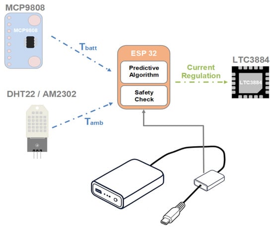
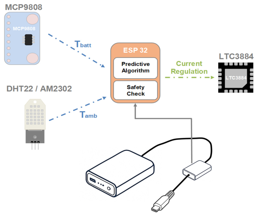
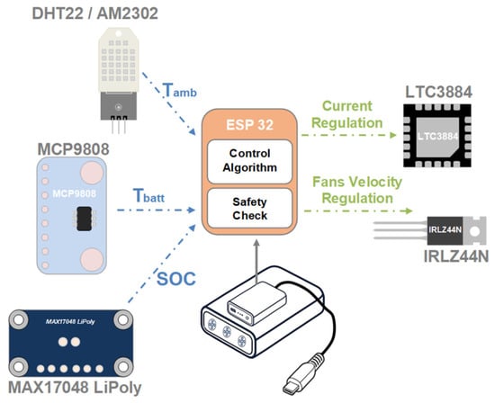
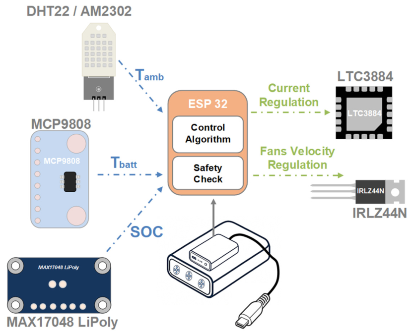
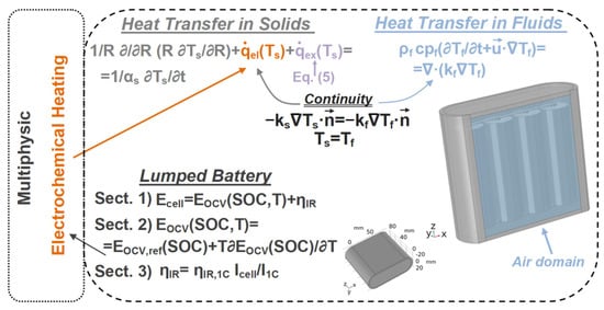
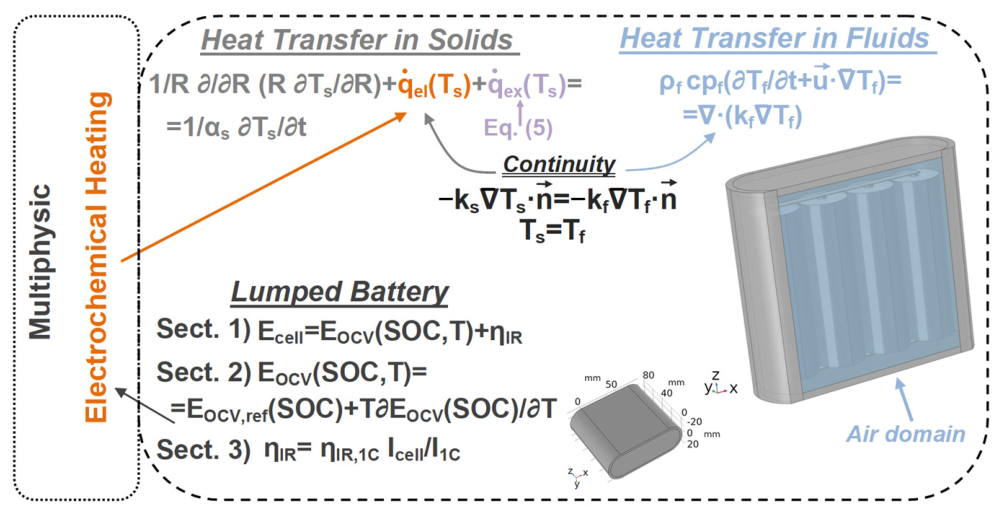
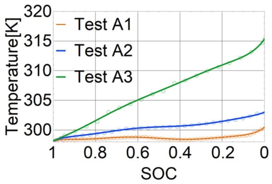
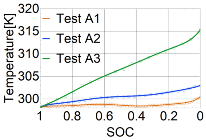
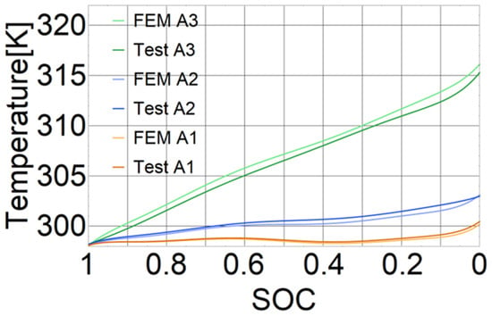
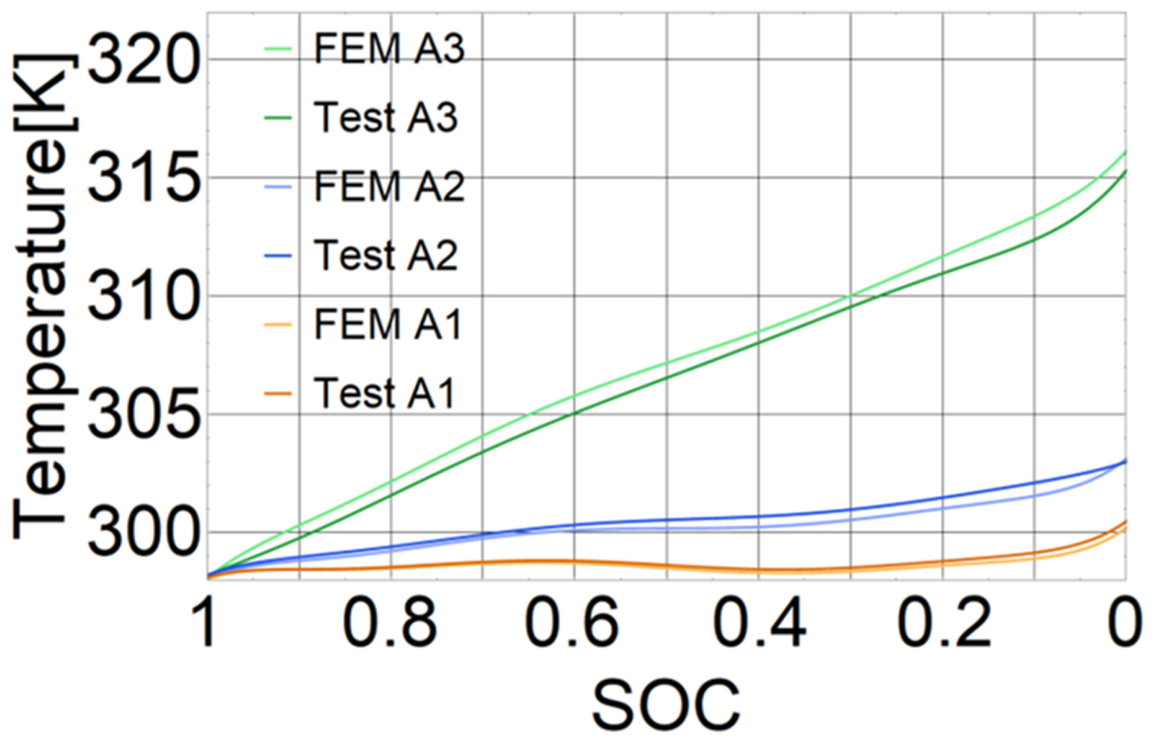
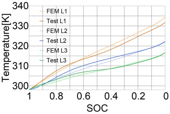
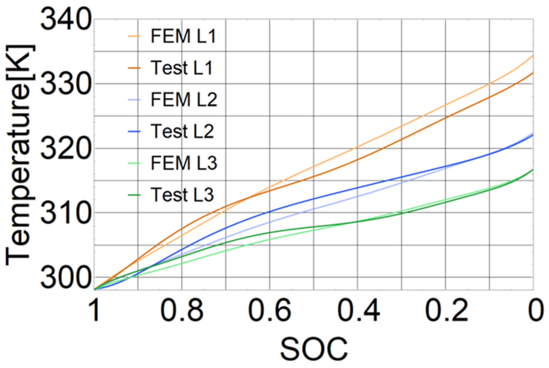
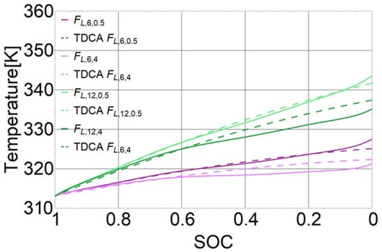
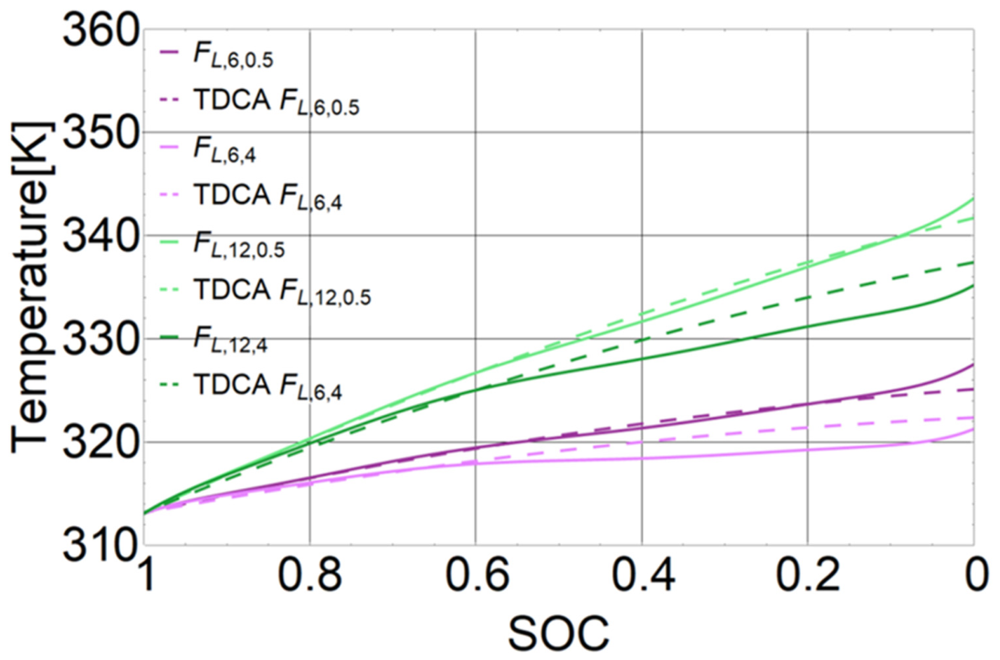
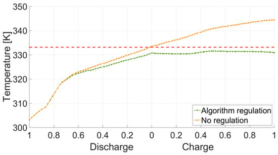
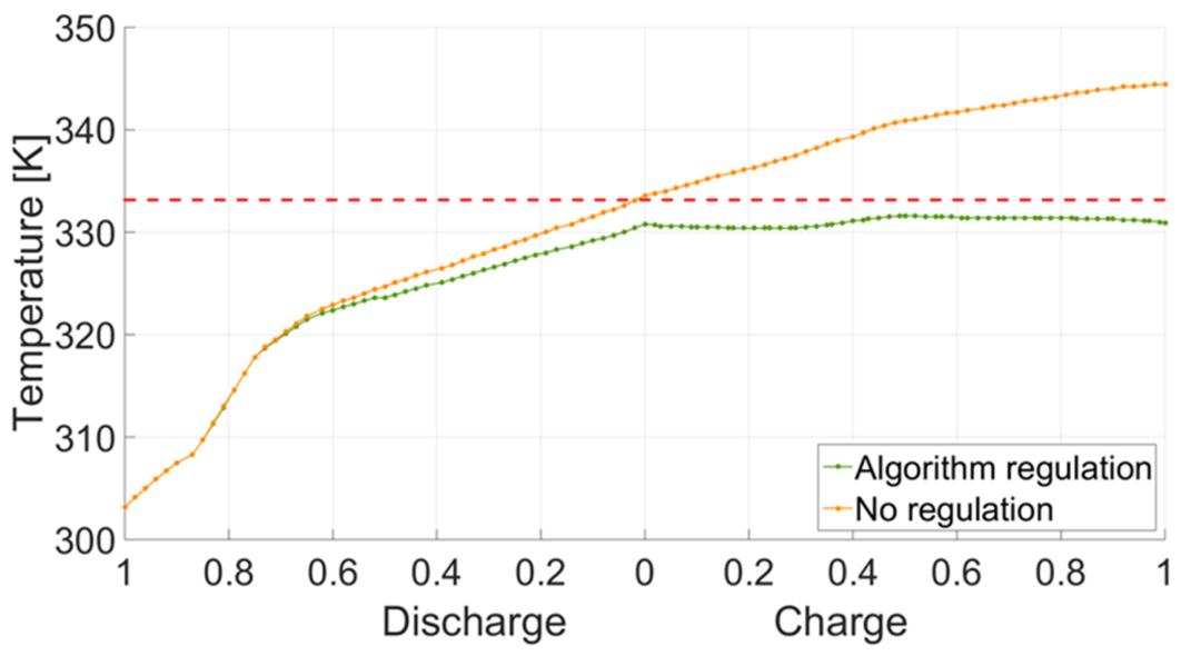

Disclaimer/Publisher’s Note: The statements, opinions and data contained in all publications are solely those of the individual author(s) and contributor(s) and not of MDPI and/or the editor(s). MDPI and/or the editor(s) disclaim responsibility for any injury to people or property resulting from any ideas, methods, instructions or products referred to in the content. |
© 2026 by the authors. Published by MDPI on behalf of the International Institute of Knowledge Innovation and Invention. Licensee MDPI, Basel, Switzerland. This article is an open access article distributed under the terms and conditions of the Creative Commons Attribution (CC BY) license.