


Abstract
Conventional industrial manipulators are often costly and come with steep learning curves, which limits their scalability in hands-on robotics education. This paper presents a compact and modular vision-guided sorting platform based on a 4-DOF SCARA robot, designed for rapid assembly, reconfiguration, and beginner-friendly deployment in laboratory courses. A collaborative visual perception strategy is proposed, which introduces a lightweight YOLOv8 algorithm for robust material category recognition, while HSV-based color segmentation and Hough circle localization are utilized to extract sub-pixel centroid features. The pixel measurements are mapped to the robot base frame through an integrated nine-point hand–eye calibration model, and joint commands are generated via a joint-space quintic polynomial interpolation algorithm to ensure continuity and avoid kinematic singularities. The overall system adopts a hierarchical architecture in which the vision host communicates target commands to a motion controller via TCP/IP, while joint actuators are driven through a CAN bus. Feasibility is first verified in a Webots digital prototype with synchronized conveyor and manipulator control, and is then validated on a physical platform equipped with a compliant TPU-based soft gripper to improve grasp tolerance under localization noise. Experiments demonstrate that the system achieves an average recognition accuracy of 98.1% and a mean positioning error of 0.189 mm. The proposed platform provides an extensible testbed for teaching kinematics, perception-to-control integration, and modular robotic system development.
1. Introduction
With the profound advancement of Industry 4.0 and intelligent manufacturing, industrial robots have become the core execution units of flexible production lines. In lightweight logistics and automated sorting scenarios, SCARA manipulators are widely applied in precision operations such as electronic assembly and pharmaceutical packaging due to their high speed and precision in the horizontal plane, as well as high rigidity in the vertical direction [1,2,3]. Given the significant role of SCARA manipulators in modern industry, constructing a robotic visual sorting experimental platform that closely resembles actual working conditions and features highly “white-box” control capabilities holds great educational and engineering value for cultivating students’ full-chain system integration abilities in “perception–decision–control” [4].
However, achieving highly robust vision-guided grasping still faces numerous technical challenges. At the visual perception level, traditional localization algorithms often rely on color space features (e.g., HSV) for object segmentation [5,6,7]; however, their recognition rates are highly susceptible to fluctuations under drastic illumination changes or environmental noise interference. In recent years, deep learning-based object detection algorithms (such as the YOLO series) have demonstrated significant advantages in material category determination and angle estimation, providing strong support for robotic grasping in complex backgrounds [8].
In the coupling phase of perception and execution, hand–eye calibration is the core key to ensuring system precision [9]. How to achieve high-precision alignment between the image pixel coordinate system and the manipulator base coordinate system by constructing a rigorous homogeneous transformation mapping model has always been a research hotspot in the robotics field. Addressing the classical hand–eye calibration problem, researchers have proposed various solving algorithms based on iterative optimization and reprojection error minimization derived from the AX = XB model [10,11,12]. Recently, calibration technology has been evolving towards global optimality and cross-modal fusion. For instance, calibration robustness in complex workstations has been enhanced through dual Kronecker products [13], symbolic solution optimization [14], and graph theory-based calibration architectures [15]. Meanwhile, methods integrating 3D vision sensors [16,17,18], point cloud registration techniques [19], and physical modeling of high-precision calibration spheres [20] have further reduced calibration residuals. For specific industrial scenarios, strategies utilizing generative adversarial networks (GANs) [21], neural network optimization [22], and the combination of homography matrices [23] or TCP-assisted calibration [24] have greatly improved calibration flexibility. Furthermore, research on hand–eye consistency in digital twin environments [25] and calibration compensation based on recognition feedback in special operations like live-line work [26] have provided diverse pathways for the engineering application of vision systems [27,28,29].
At the physical execution level, the motion stability of the manipulator relies heavily on precise kinematic modeling and trajectory planning [30,31]. To resolve the motion step problem of the end-effector during dynamic sorting processes, joint-space kinematic analysis and trajectory smoothing algorithms are crucial [32]. The introduction of quintic polynomial interpolation, path searching based on improved RRT algorithms [33], and intelligent optimization algorithms such as SA-IPSO [34] can effectively guarantee the smoothness of the manipulator during high-speed operations.
To address the common issues of closed commercial controllers and insufficient decoupling between visual perception and motion control in current educational experimental platforms, this study designs and implements a cost-effective, modular SCARA manipulator visual sorting experimental platform. The main contributions of this work are as follows: Firstly, by integrating a lightweight YOLO recognition operator with a high-precision hand–eye calibration model, a collaborative perception mode of “category recognition and spatial localization” is constructed. Secondly, a joint-space quintic polynomial interpolation algorithm is introduced to achieve smooth grasping trajectories while avoiding kinematic singularities. Finally, a digital twin verification system is built using the Webots physics engine, and a TPU compliant adaptive gripper is employed to effectively absorb perception noise at the hardware level, significantly improving the sorting success rate in non-ideal environments.
2. Overall System Design
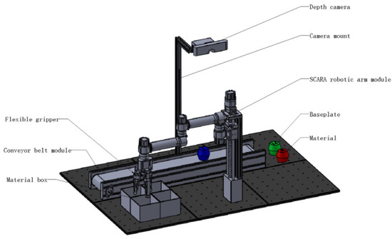
The proposed vision-based sorting experimental platform comprises a base plate, a conveyor-belt module, a SCARA manipulator, a compliant gripper, material bins, a depth camera, and the objects to be sorted (Figure 1). The base plate serves as the primary mounting datum of the system. It is bolted to a leadscrew lift stage and the depth-camera bracket, providing rigid and stable support for all functional modules. The SCARA manipulator adopts a four-degree-of-freedom configuration, consisting of three revolute modules and one prismatic (linear) module. The linear axis is implemented using a dual-axis ball-screw linear slide, while the three revolute modules are connected to the upper and forearm links via detachable bolted joints, enabling rapid assembly and reconfiguration. A detachable rotary joint between the two-arm links is realized through a dedicated rotation module. A compliant end-effector is mounted at the manipulator wrist through a rotary module. The gripper integrates a flange plate, a stepper motor and driver, a linkage transmission mechanism, and three flexible fingers arranged in an equilateral-triangle layout. The fingers are fabricated from TPU using 3D printing to provide self-adaptive soft grasping. To enhance grasp stability, the contact surfaces incorporate anti-slip textures (e.g., wavy or honeycomb patterns). The depth camera is fixed above the workspace via a bracket to acquire object images in real time. During operation, the conveyor transports incoming objects, and the material bins are used to store sorted items by category.
Figure 1.
Three-dimensional model of the vision-based sorting platform.
The platform adopts a hierarchical control architecture consisting of a vision host (upper computer) and a motion-control unit (lower computer). The vision host integrates a depth camera with a terminal device and performs object recognition and sorting decision-making using image-processing algorithms. The extracted target pose information is transmitted to the lower computer via the CAN communication protocol. Based on these commands, the lower computer coordinates the servo drives, the leadscrew lift stage, the SCARA manipulator, and the compliant gripper to execute synchronized motions, thereby forming an integrated logistics sorting solution that combines visual perception, command communication, and motion execution.
3. Kinematic Analysis of the Manipulator
3.1. Establishment of the Homogeneous Coordinate Frames
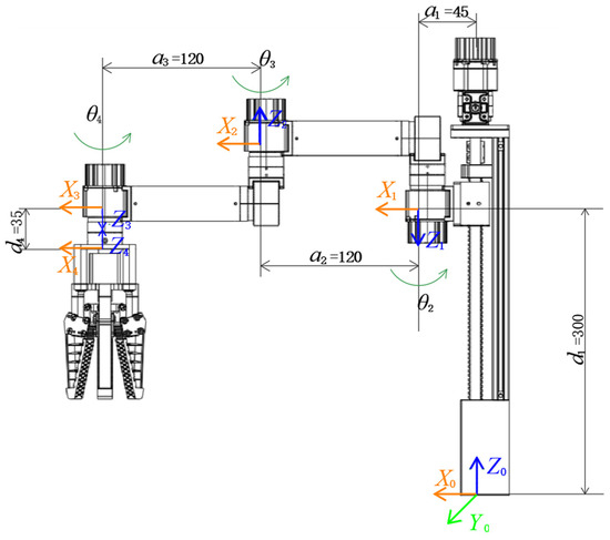
The kinematic model is formulated using the Standard Denavit–Hartenberg (SD–H) convention. The base of the manipulator is defined as the reference frame . For each link, a local coordinate frame is rigidly attached to the distal end of link , i.e., on the side adjacent to joint . The -axis is aligned with the motion axis of joint . The -axis is chosen along the common normal between the axes of joints and , pointing toward joint . The -axis is then determined by the right-hand rule, satisfying . The resulting coordinate-frame assignment for the SCARA manipulator is illustrated in Figure 2.
Figure 2.
Assignment of homogeneous coordinate frames for the manipulator.
The SD–H parameters of the SCARA manipulator are summarized in Table 1. denotes the rotation about the -axis that aligns with , with the positive direction defined by the right-hand rule. represents the translation along the -axis from frame to , taken as positive along . is the rotation about the -axis that aligns with , positive in the direction. denotes the translation along the -axis from to , taken as positive along .
Table 1.
SD–H parameters of the manipulator.
The geometric parameters of the manipulator listed in Table 1 are strictly derived based on the requirements of desktop-level sorting education. The link length parameter provides a forward offset for the base. The equal-length design of the upper arm () and the forearm () is intended to maximize the dexterous workspace area in the horizontal plane, ensuring that the robotic arm can fully cover both the conveyor picking zone and the material box placement area on the base plate. Additionally, the maximum stroke of the lead screw module corresponding to the joint translation is set to 300 mm, which provides sufficient vertical clearance for the downward grasping and upward obstacle avoidance of the compliant gripper.
3.2. Forward Kinematics of the Manipulator
To determine the pose of the end-effector, forward kinematics is derived by mapping the known actuated joint variables to the Cartesian position and orientation of the tool frame [30,32]. According to the coordinate transformation rules between adjacent links, the relationship between two consecutive link frames can be expressed by a homogeneous transformation matrix:
Substituting the SCARA manipulator’s SD–H parameters into Equation (1) yields the homogeneous transformation matrices between four consecutive joint frames:
By successively multiplying the adjacent-link transformation matrices in Equation (2), the overall forward kinematics from the base frame to the end-effector frame can be obtained as
In Equation (3), [], [], and [] are the components of the end-effector’s three orthonormal axis unit vectors projected onto the x-, y-, and z-axes of the base frame, respectively. The vector []T denotes the translation of the end-effector with respect to the base frame.
From Equation (4), the end-effector position components , , and can be computed accordingly.
3.3. Inverse Kinematics Analysis
The objective of inverse kinematics is to determine the joint variables of all actuated axes for a prescribed target pose, such that the end-effector reaches the desired position and orientation [30].
From Equation (4), the vertical displacement satisfies , yielding
Let the in-plane orientation be defined as . The end-effector rotation matrix can then be written as
Accordingly, the following relations are obtained:
Therefore, can be obtained directly from the geometric constraint as
Define , then the planar translation equations can be rearranged into a linear system with respect to the auxiliary angle ψ:
Solving Equation (9) yields
and thus
Accordingly, the second joint angle is computed as
Finally, using the wrist angle is obtained by
In summary, given the target position and the in-plane orientation , the joint variables , , and can be determined explicitly (with admitting the usual multiple-configuration solutions due to the operation).
3.4. Workspace and Singularity Analysis
The workspace and singularity analysis of the manipulator is a critical step in verifying the rationality of its configuration for practical sorting tasks. Based on the mechanical structure and anti-collision limit design of the physical prototype, the angular range of the large-arm rotation joint (Joint 2) is set to , the angular range of the small-arm rotation joint (Joint 3) is set to , and the effective stroke of the Z-axis linear lift module (Joint 1) is 300 mm. Combined with the forward kinematics equations, the effective workspace of the manipulator is a symmetric fan-shaped cylindrical cross-section area stretched by 300 mm along the Z-axis. Considering the maximum arm span of 240 mm, this workspace capacity fully covers the dynamic conveyor belt area and the material sorting boxes on both sides as configured in this experiment. The absence of sorting blind spots ensures the feasibility of tasks from the perspective of kinematic boundaries.
Furthermore, analyzing the Jacobian matrix is key to avoiding kinematic control instability. Since the Z-axis translation and end-effector orientation rotation are decoupled in this SCARA configuration, the core singularities of the system depend on the two-link mechanism (large arm and small arm) in the horizontal plane. The determinant of the Jacobian matrix $J$ corresponding to the planar motion can be derived as follows:
According to the definition of a singularity, when (i.e., ), the large arm and small arm are in a fully extended collinear state. At this point, the manipulator loses one degree of freedom in the radial direction of the end-effector and falls into a boundary singularity state. Utilizing Cartesian space planning for the inverse solution in this state would result in joint angular velocities tending toward infinity. To resolve this theoretical hazard, this experimental platform adopts a dual avoidance strategy at the control level: first, in the workbench layout, the high-frequency picking zone (conveyor) and the placement zone (material boxes) are positioned at the lateral front of the manipulator, ensuring that the primary operational trajectories remain within high-dexterity regions; second, in the lower-level motion control, the system employs a “Joint Space Interpolation” algorithm to generate trajectories, performing smooth transitions directly on target joint angles. This fundamentally avoids the motor speed surges that may occur when Cartesian space linear interpolation crosses singularities, thereby ensuring the safety and stability of the experimental teaching process.
4. Digital Twin Simulation and Kinematic Verification Based on Webots
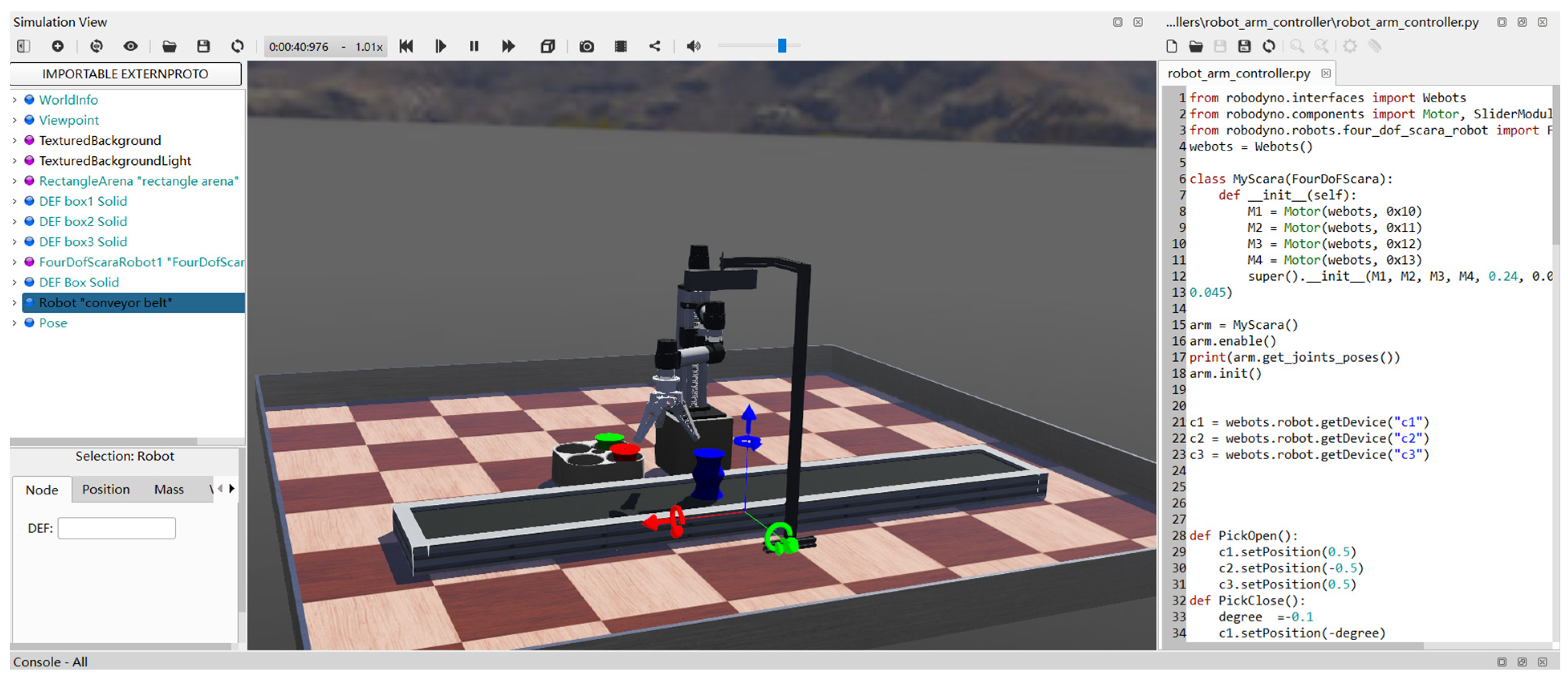
A simulation of the experimental platform was developed in Webots, and the constructed virtual environment is shown in Figure 3. The scene was organized using Webots’ hierarchical scene-tree structure. The main components include a 4-DOF SCARA manipulator, an end-effector gripper, a conveyor belt, a depth camera with a mounting bracket, and the target objects/material blocks. Each module is assigned a unique DEF identifier, facilitating programmatic access as well as state monitoring and control during simulation.
Figure 3.
Webots-based simulation environment of the manipulator system.
4.1. Virtual–Real Equivalent Modeling and System Initialization
In the Webots simulation environment, the manipulator model is not a simple geometric mapping; it is a physical reconstruction based on the SD-H geometric parameters shown in Table 1 and the dynamic properties of the actual links. Each execution node is structurally defined through the scene tree, with core drive units precisely mapped to the control program via unique DEF identifiers. At the control interface level, the simulation system incorporates the same CAN 2.0B bus communication protocol logic as the physical prototype, enabling independent decoupled control of the four virtual joint motors by assigning IDs 0 × 10 to 0 × 13. Zero-position calibration tests demonstrate that the joint positioning deviation between the virtual model and the physical entity is less than 0.5°, establishing an accurate baseline for subsequent virtual–real collaborative experiments.
4.2. Joint-Space Trajectory Planning and Smoothness Verification
To satisfy the frequent start-stop requirements during the sorting process, this study adopts a joint-space quintic polynomial interpolation algorithm to avoid potential joint velocity jumps when the manipulator crosses collinear singularity points in the workspace. During simulation, the controller constructs time-dependent polynomials in the joint space that satisfy displacement, velocity, and acceleration boundary constraints based on the target joint vectors derived from inverse kinematics.
The recorded kinematic response curves indicate that during high-speed transfer cycles, the motion trajectories of each joint exhibit high degrees of smoothness and continuity at the end-effector. The acceleration curves are devoid of step changes, strictly fulfilling continuity requirements. Unlike conventional trapezoidal velocity planning (which only achieves continuity and introduces infinite jerk at phase transitions due to acceleration step changes), the second derivative of the quintic polynomial yields a continuous cubic function for acceleration, preventing any discrete jumps. From a physical perspective, this continuity ensures a bounded jerk (the rate of change in acceleration), which is crucial for minimizing mechanical shocks, suppressing system vibrations, and protecting the joint motors during high-speed pick-and-place operations. These simulation results theoretically validate the control algorithm’s effectiveness in suppressing mechanical vibrations and avoiding dynamic surges, ensuring the operational stability and safety of the physical system.
4.3. Comparison Between Simulation and Physical Experiments
To validate the fidelity of the digital twin, a preliminary comparative analysis between the Webots simulation and the physical platform was conducted. The zero-position calibration tests demonstrated that the joint positioning deviation between the virtual model and the physical entity is strictly maintained below 0.5°. Furthermore, when tracking identical target points, the simulation model yielded an ideal average positioning error of 0.142 mm, whereas the physical platform achieved a mean error of 0.189 mm (with a standard deviation of 0.028 mm). This sub-millimeter discrepancy is primarily attributed to physical assembly clearances and inherent visual localization noise. These highly consistent metrics confirm the equivalence of the dynamic parameters, proving that the simulation serves as a reliable bridge for algorithm pre-testing.
5. Software Function Design and Control Algorithms
5.1. Collaborative Visual Perception
The system implements a collaborative perception strategy that decouples object localization from category recognition. First, an “Eye-to-Hand” configuration is calibrated using the Zhang Zhengyou method for intrinsic parameters, followed by a nine-point calibration model to derive the affine transformation matrix between the pixel plane and the robot base frame. This ensures that object coordinates can be accurately mapped into the physical workspace in real-time.
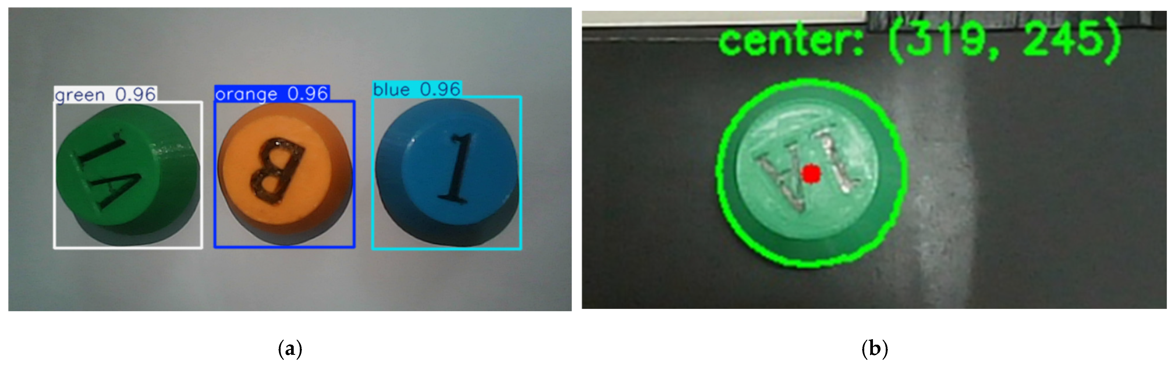
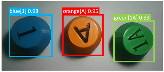
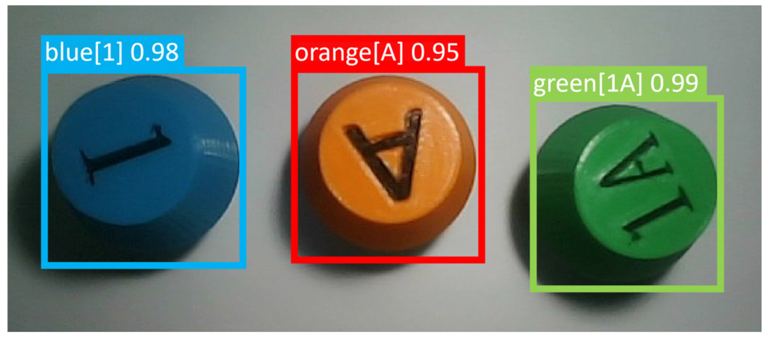
To enhance robustness under varying lighting, material color is filtered in the HSV space, and sub-pixel centroid coordinates are extracted via the Hough Circle Transform (as shown in Figure 4). Simultaneously, a lightweight YOLOv8 model is integrated exclusively for material type identification (as shown in Figure 5), rather than coordinate regression. This approach leverages the high classification accuracy of deep learning while maintaining the sub-millimeter localization precision of geometric algorithms, effectively overcoming the instability of end-to-end neural networks in precision tasks.
Figure 4.
Block recognition results: (a) Color recognition: (b) Center localization via Hough circle detection.
Figure 5.
Material category recognition based on the YOLO algorithm.
5.2. Distributed Control and Trajectory Planning
The execution layer adopts a distributed control architecture via the CAN 2.0B bus with a 10 ms sampling period. To ensure motion stability, all joints are operated in a position-closed-loop mode with software-defined safety limits. A joint-space quintic polynomial interpolation algorithm is employed to generate trajectories by constraining the displacement, velocity, and acceleration at both start and end points to zero. This mathematical constraint ensures that the entire motion profile remains smooth and continuous, effectively mitigating the risk of kinematic singularities inherent in Cartesian linear interpolation.
5.3. System Workflow
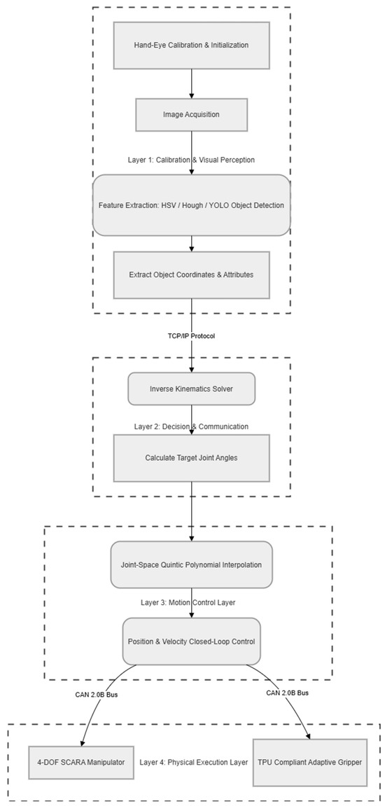
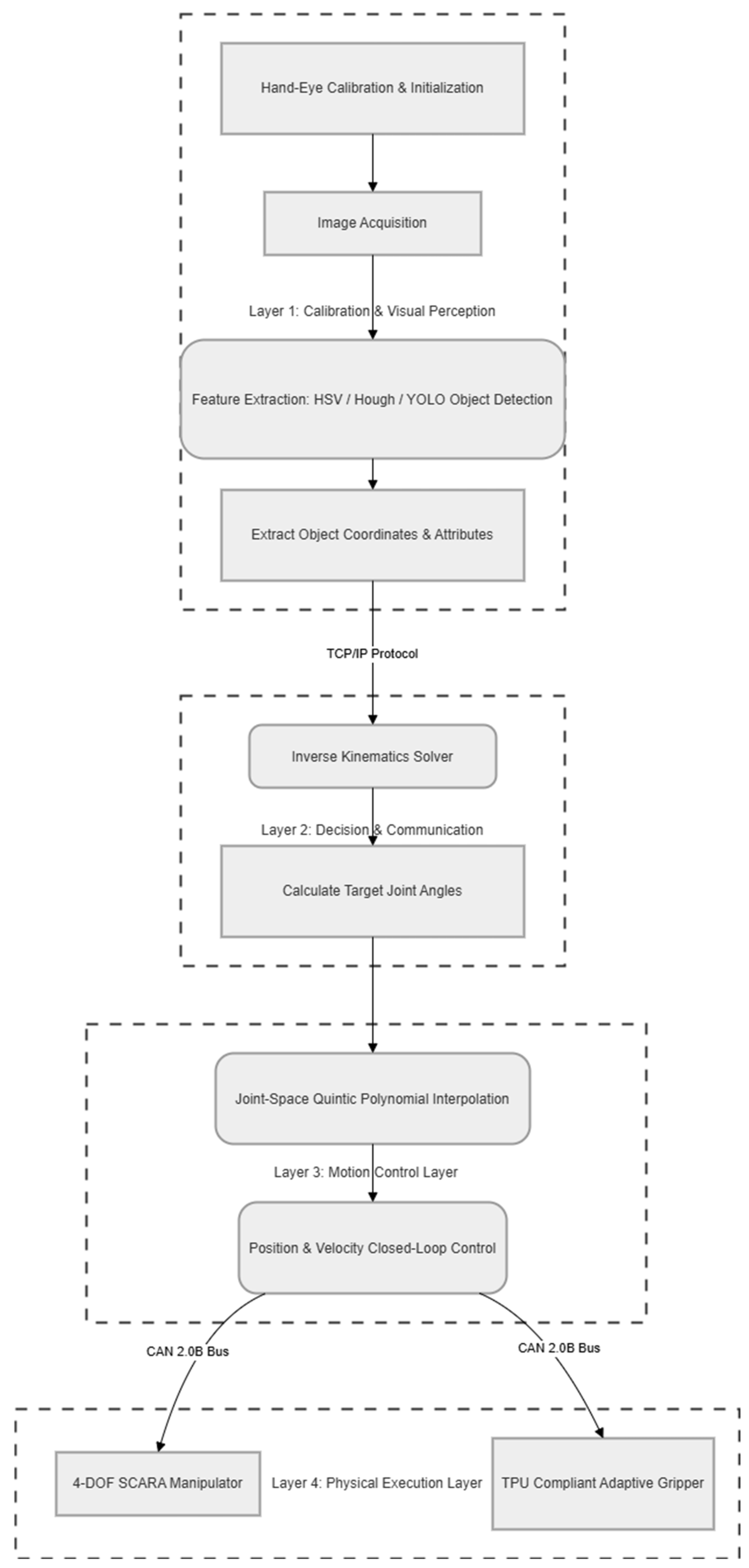
The “Perception–Decision–Execution” workflow is structured into four decoupled layers, as illustrated in Figure 6. The process begins with feature extraction and coordinate mapping, followed by inverse kinematics calculation. Smooth trajectories are then generated via joint-space interpolation and dispatched as high-frequency commands to the physical SCARA manipulator and the compliant TPU gripper.
Figure 6.
“Perception–Control–Execution” collaborative workflow of the SCARA-based visual sorting platform.
6. Experiments and Analysis
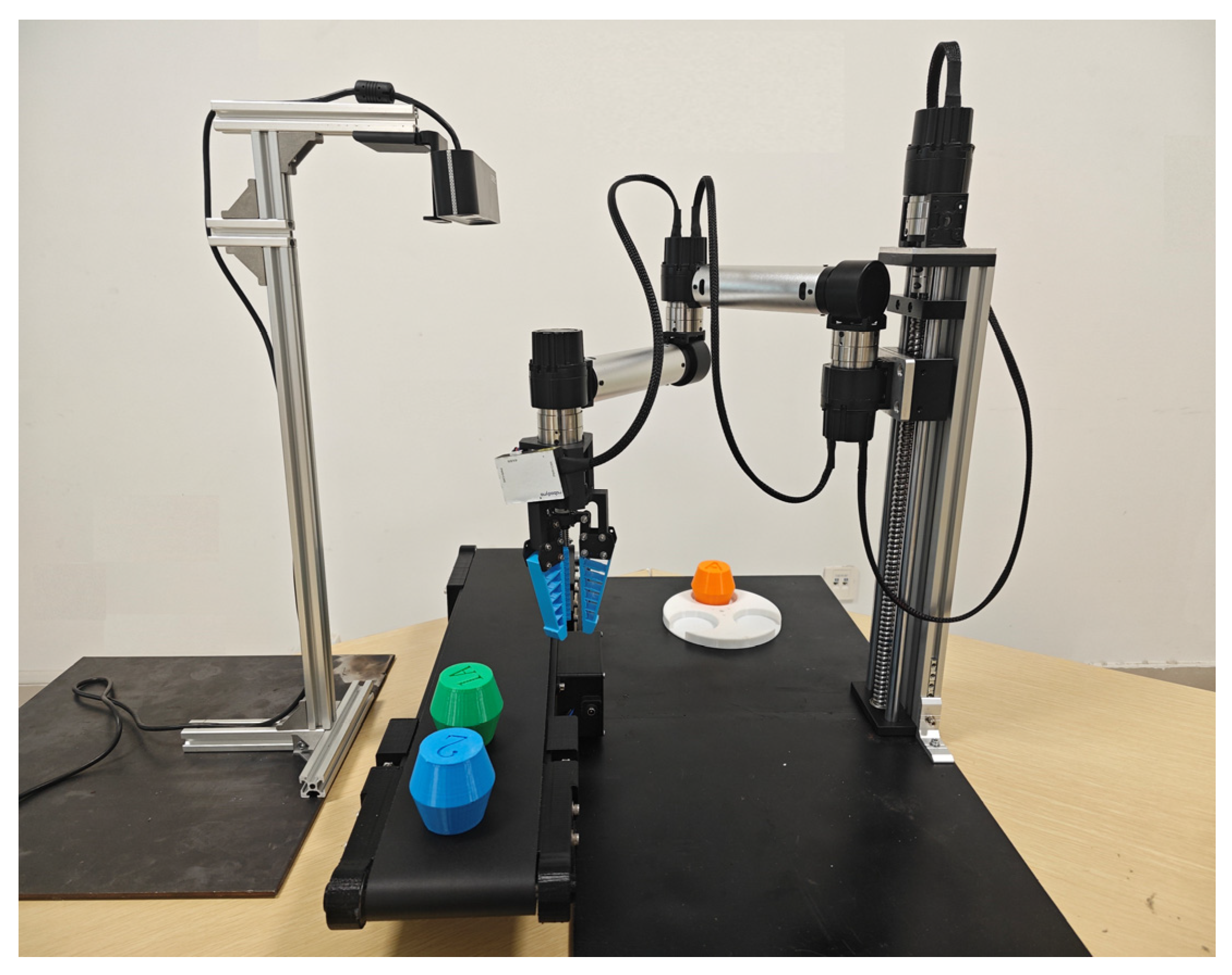
The physical experimental platform is shown in Figure 7. Building upon the fixed-point grasping validated in simulation, the real-world system integrates the vision perception module to identify the object’s color category and to estimate the real-time coordinates of its circular centroid. The extracted information is transmitted to the host terminal for processing and then forwarded to the manipulator controller, where it is converted into joint-level motion commands (i.e., motor rotation angles) via inverse kinematics. This pipeline enables vision-guided sorting with the proposed modular manipulator platform.
Figure 7.
Modular vision-based sorting teaching platform.
The entire platform is controlled by a host terminal. During operation, objects with different shapes and colors are placed on the conveyor and transported into the effective sensing region of the depth camera. The camera captures the object’s color category and the real-time centroid coordinates and transmits these data to the terminal controller. Based on the centroid position, the controller performs kinematic computation to convert the target Cartesian coordinates into joint-level commands, enabling dynamic coordination between the end-effector and the moving object in the – plane. Meanwhile, a leadscrew lift stage drives the compliant gripper to descend along the -axis. During descent, the terminal commands the stepper motor to open the gripper. Once the end-effector reaches the predefined grasping zone, the fingers close to achieve a stable grasp, after which the gripper is lifted back to a safe height. The terminal then selects the corresponding placement location according to the recognized color category. The target placement coordinates are transformed into joint angles via kinematic computation, and the manipulator transports the grasped object to a position directly above the designated bin. The gripper is subsequently opened to release the object into the bin, completing one sorting cycle. Finally, the manipulator returns to its initial standby pose in preparation for the next cycle.
The layout of the experimental scene is shown in Figure 7. The vision module is installed directly above and parallel to the conveyor belt. The conveyor belt module is positioned at the edge of the robotic arm’s working radius and remains parallel to the platform, while the material boxes are placed inside the robotic arm’s workspace. The experimental materials consist of three colors: orange, green, and blue. Their structure is a composite form created by joining two vertically symmetric truncated cones, with characters such as “1, 2, 1A, 2B, A, B” marked on the surface to distinguish categories. The experimental process is divided into three parts: first, 100 sets of performance experiments were conducted to evaluate the accuracy and timeliness of information transmission during the interaction between the robotic arm and the vision module; second, 100 sets of comparative experiments on recognition accuracy were performed for materials with different colors and morphological features; and finally, 50 sets of accuracy verification experiments were conducted to assess the motion precision of the robotic arm at various spatial positions.
It is worth noting that, constrained by ambient illumination and camera resolution, the centroid coordinates extracted via Hough circle detection occasionally exhibit minor fluctuations, subsequently leading to theoretical deviations in the joint commands derived from inverse kinematic calculations. However, at the physical execution layer, benefiting from the physical compliance of the TPU soft gripper at the end-effector, the jaws can adaptively conform to the contours of the materials. This effectively absorbs and compensates for the visual localization errors at the mechanical level, thereby ensuring the reliability of the grasping process.
Based on the experimental protocol described above, this study performed a quantitative analysis of the system’s performance through multiple sets of physical tests. The experiments primarily focused on evaluating the visual recognition speed, system communication efficiency, motor motion response and smoothness, as well as positioning accuracy.
6.1. System Communication
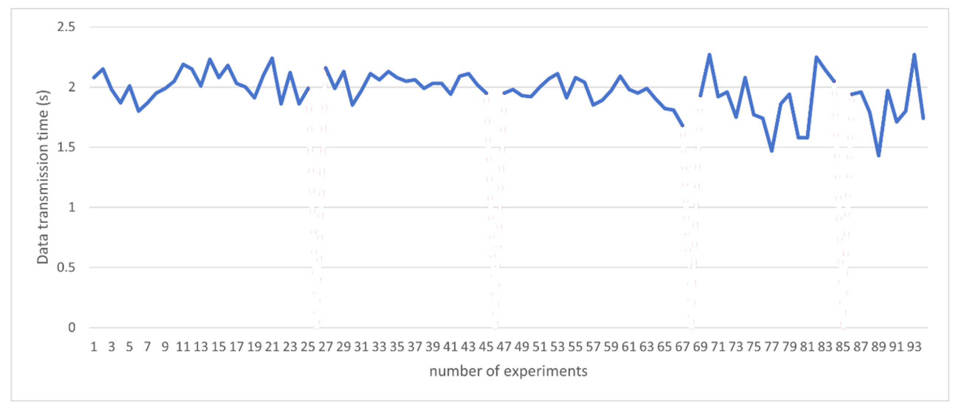
The system’s real-time communication efficiency was evaluated over 100 sorting cycles (Figure 8). Under normal conditions, the data transmission time averaged 1.95 s (ranging from 1.5 s to 2.3 s), ensuring rapid synchronization among visual perception, inverse kinematics calculation, and multi-joint execution. Occasional time drops to zero (e.g., at cycles 26, 46, 68, and 85) were caused by transient camera feature extraction failures, resulting in an overall communication success rate of 96%. Minor latency fluctuations due to wireless network variations remained within acceptable thresholds, confirming the system’s long-term operational stability.
Figure 8.
Communication time between the camera and the manipulator via port 8801.
6.2. Visual Recognition Speed
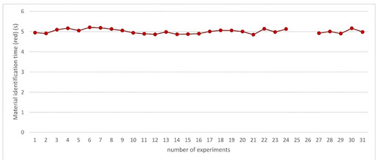
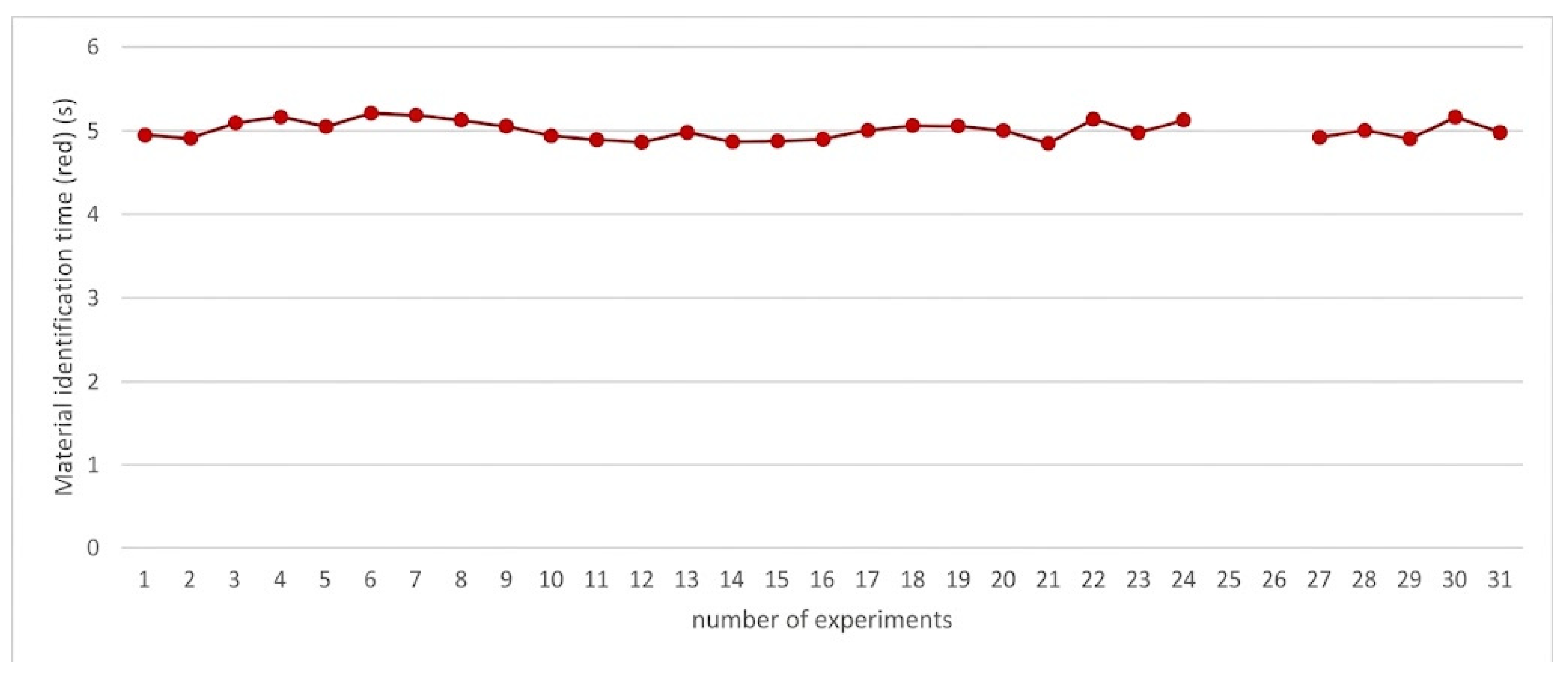
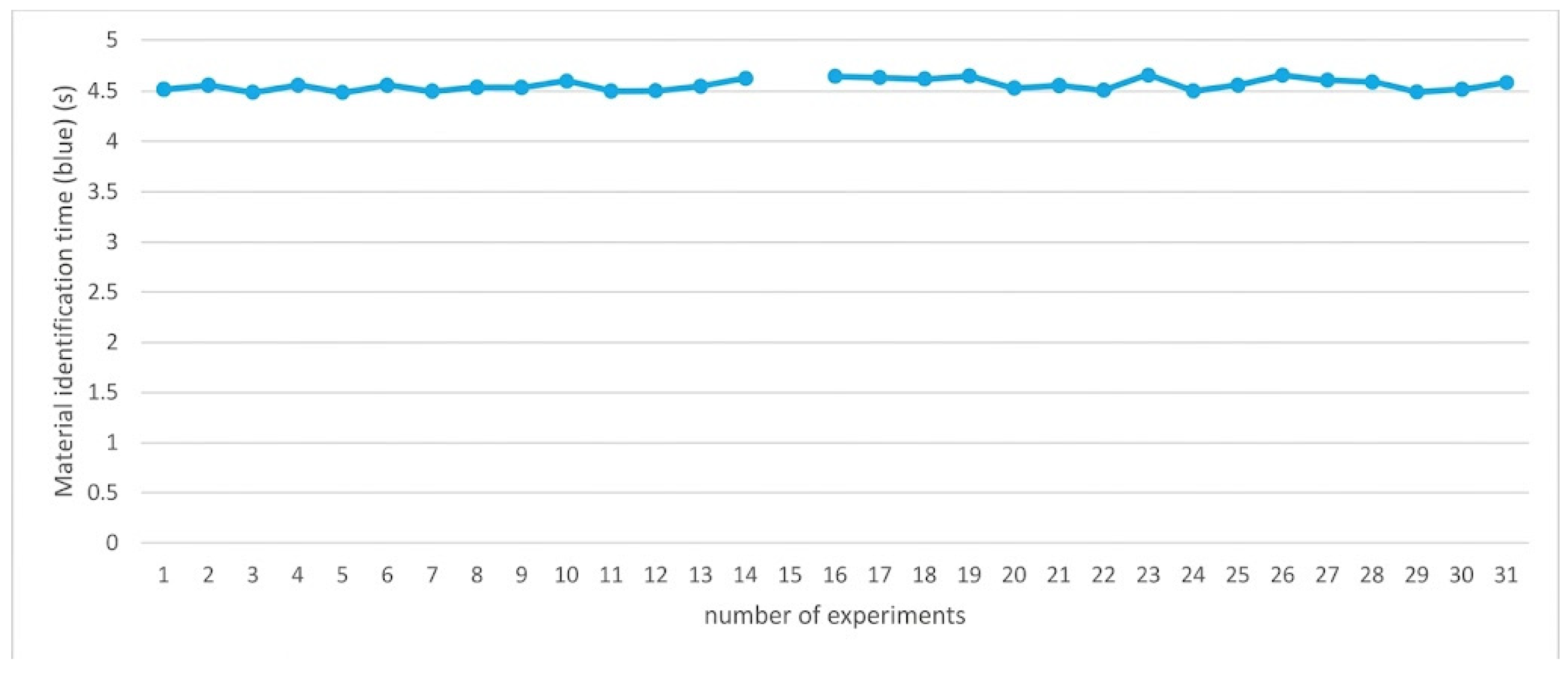
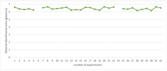
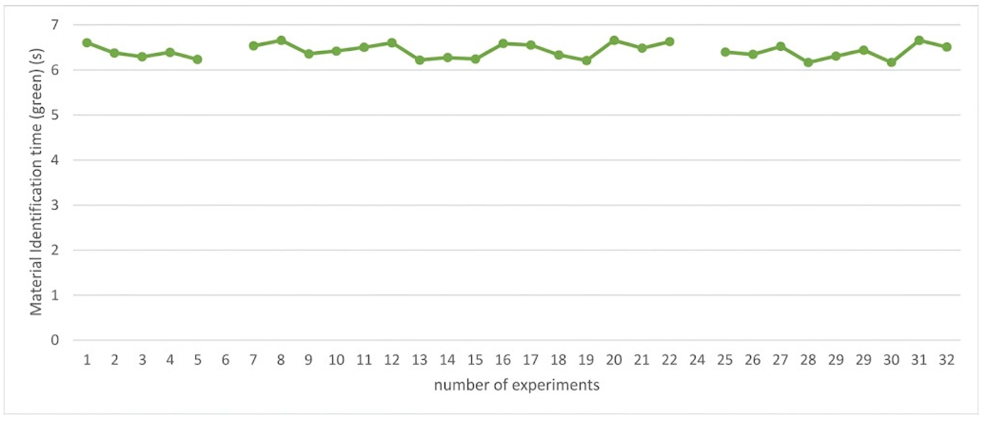
The underlying core time consumption for a single-frame recognition remains stable at approximately 11.4 ms. However, the overall perception cycles exhibit a gradient difference: approximately 5.0 s for red materials (Figure 9), 4.5 s for blue (Figure 10), and 6.5 s for green (Figure 11). This variance is logically sound, as the system is designed to accumulate and average a buffer of 30 to 50 consecutive valid frames to guarantee sub-pixel centroid stability before triggering the physical grasp. The differing geometric morphologies dictate different convergence speeds during this multi-frame filtering process, which accounts for the extended total cycle time.
Figure 9.
Recognition time for red materials.
Figure 10.
Recognition time for blue materials.
Figure 11.
Recognition time for green materials.
Furthermore, it is essential to clarify the instances of missing data, such as Experiment 26 for red materials, Experiment 15 for blue, and Experiments 6 and 23 for green. These entries act as error flags in the system log; when transient frame drops or severe specular reflections occur, the YOLO network fails to generate a valid bounding box. Consequently, the multi-frame filtering mechanism is safely aborted to trigger a system reset and remeasurement, effectively preventing erroneous grasping.
As shown in Table 2, the experimental results demonstrate that the algorithm exhibits excellent robustness under the illumination conditions of the educational platform, achieving an average accuracy of 98.1%. The underlying core time consumption for a single recognition remains stable at approximately 11.4 ms.
Table 2.
Recognition rates.
The experiment observed gradient differences in the perception cycles for different materials: approximately 4.5 s for blue materials, 5.0 s for red materials, and 6.5 s for green materials. This variance originates from the different convergence speeds of various material morphologies during the OpenCV multi-frame filtering and spatial coordinate averaging processes, reflecting the sensitivity of the system’s perception algorithm to distinguish geometric features of the targets.
The curves indicate that the recognition times for the three types of materials maintain a high degree of consistency during continuous operations, with an extremely narrow fluctuation range. This result validates the robustness of the system’s perception logic, proving its effectiveness in resisting the impact of environmental noise, such as conveyor belt vibrations, on recognition timeliness.
6.3. Motor Motion Response
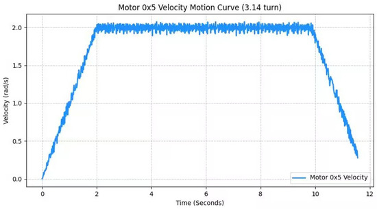
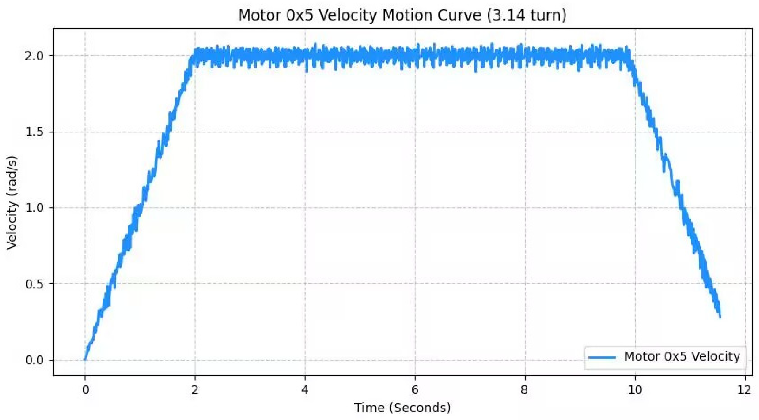
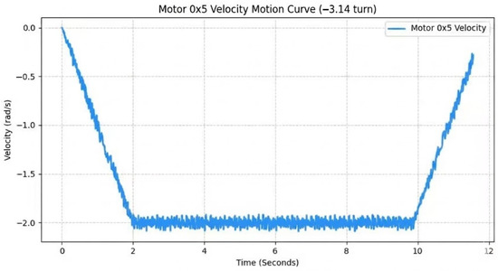
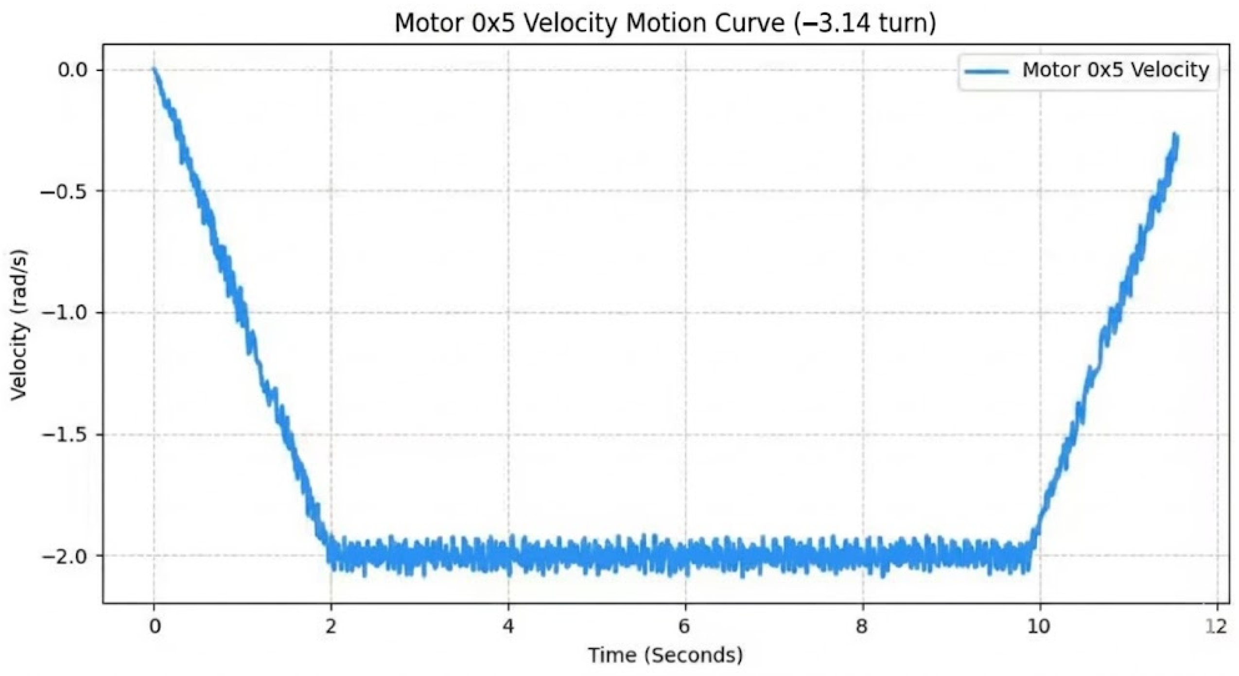
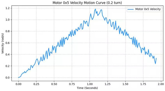
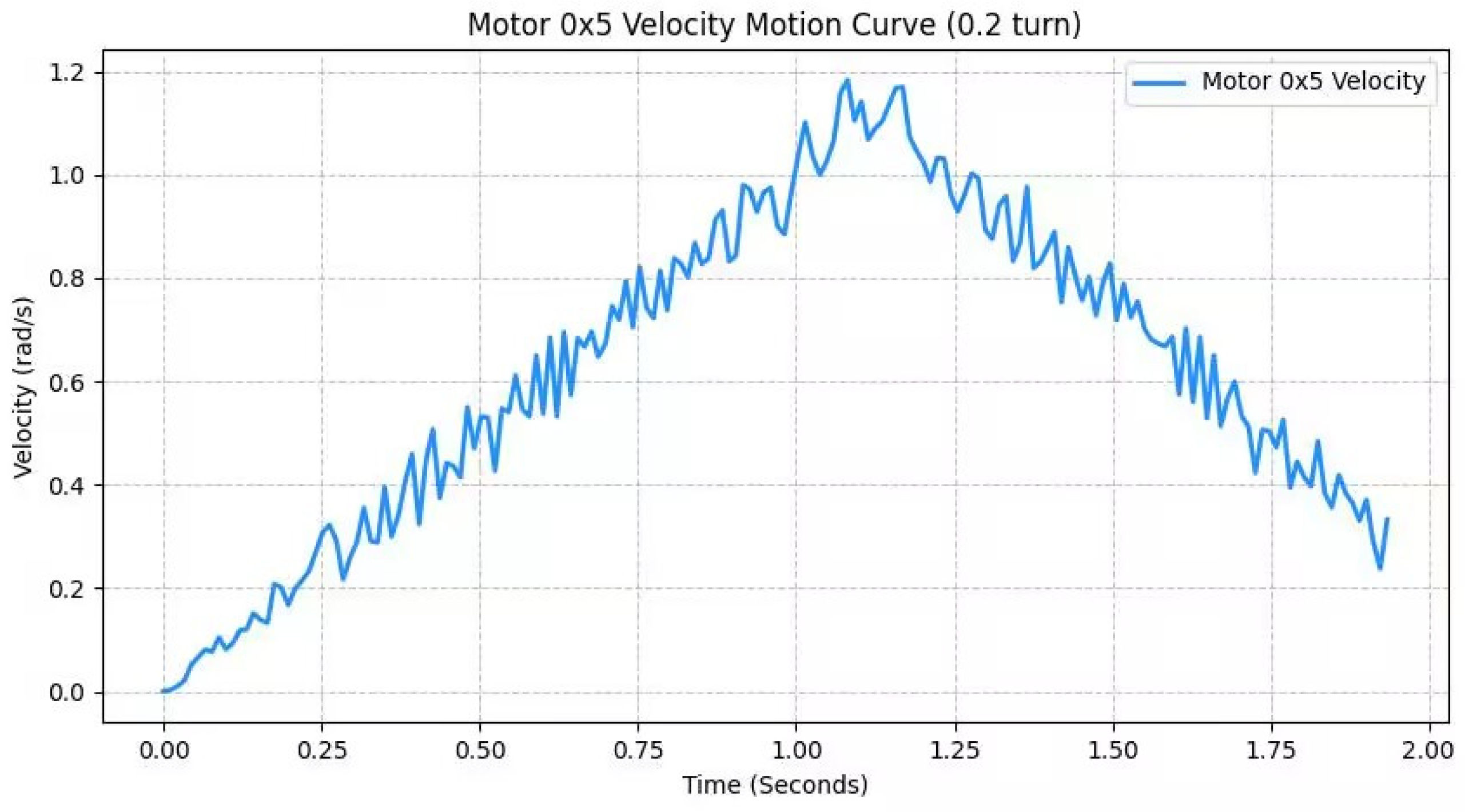
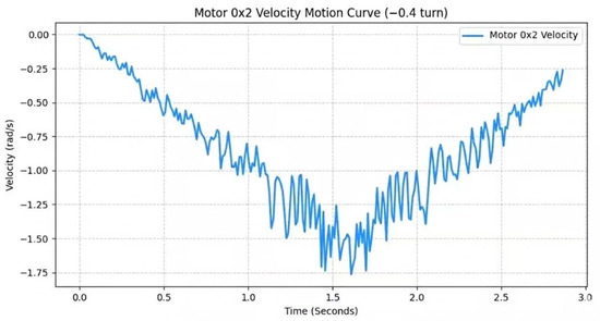
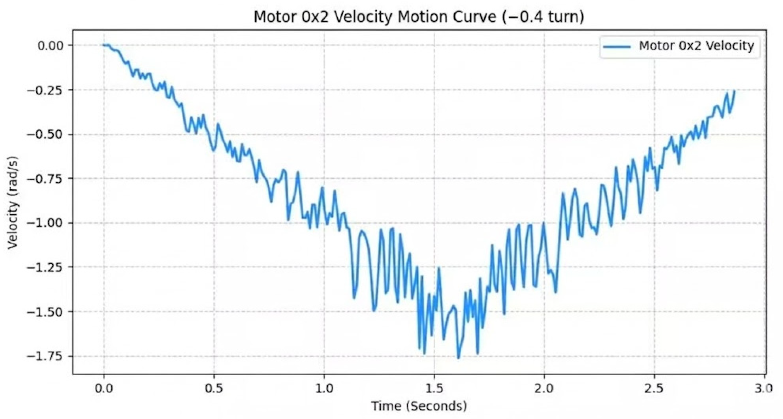
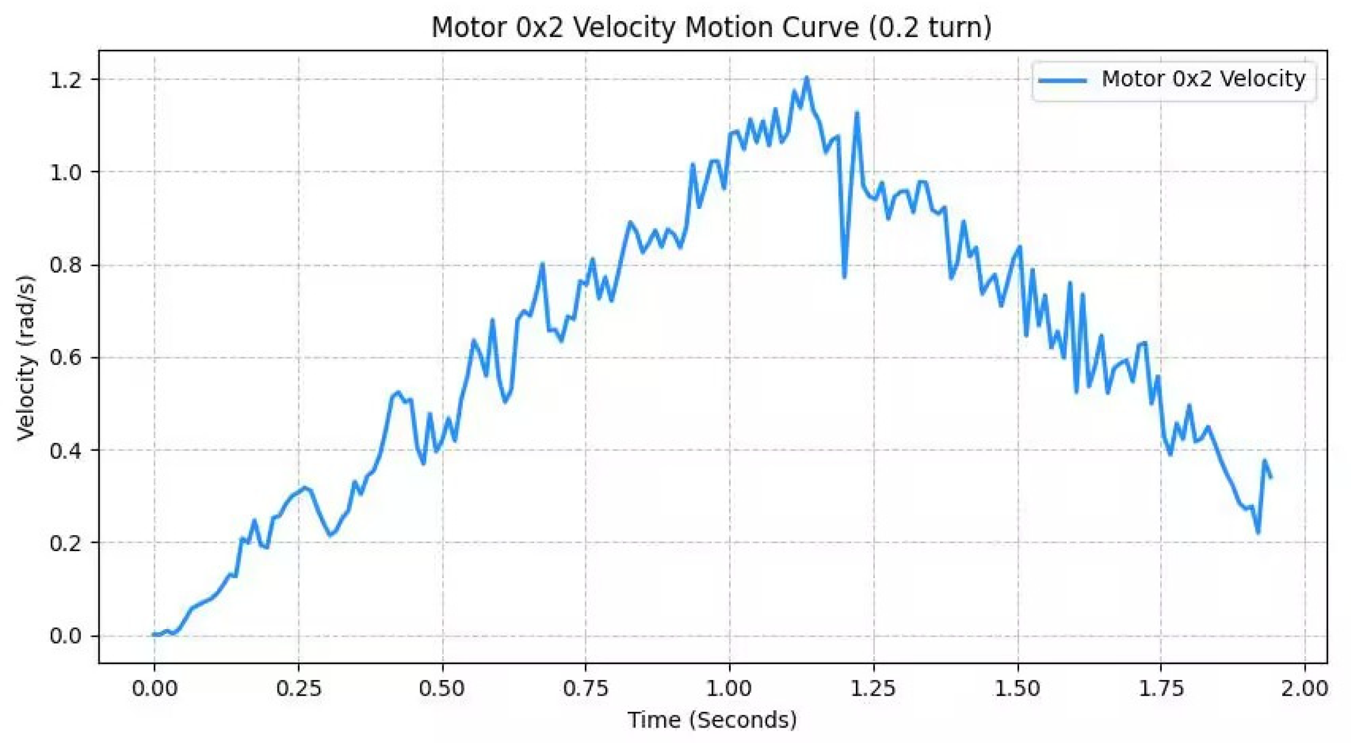
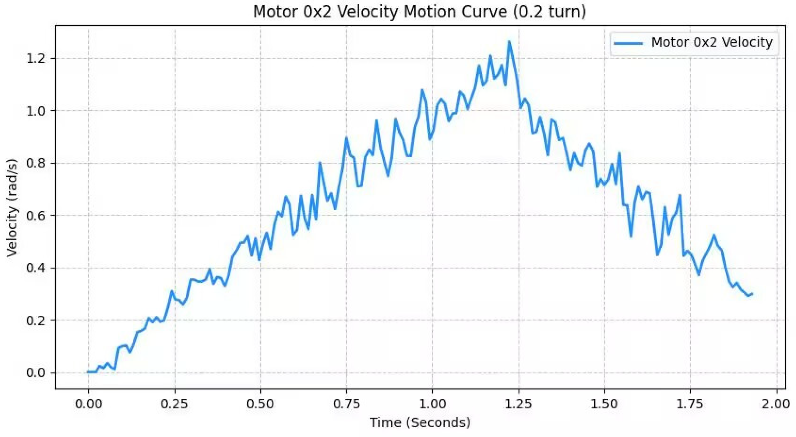
To validate the motion smoothness and control accuracy of the actuators across different sorting stages, real-time velocity curves were captured for joint motors at various manipulator positions. As illustrated in Figure 12, Figure 13, Figure 14, Figure 15, Figure 16 and Figure 17, the motion characteristics are characterized as follows: for long-stroke operations, the profiles follow a standard trapezoidal velocity plan, with the motors accelerating steadily to a cruising speed of 2.0 rad/s over approximately 2 s; the constant-velocity segment displays minimal fluctuation, highlighting robust steady-state control. For short-stroke operations, the profiles switch to a symmetric triangular distribution, where the motors transition smoothly into the deceleration phase upon reaching the peak displacement. The overall envelopes of the curve sets are continuous and smooth. Despite minor high-frequency ripples induced by closed-loop system regulation, no significant overshoot or violent oscillation is observed, confirming that the actuators maintain excellent dynamic response and motion stability under diverse operating conditions.
Figure 12.
Velocity curve of the lead screw motor (forward).
Figure 13.
Velocity curve of the lead screw motor (reverse).
Figure 14.
Velocity curve of the motor near the lead screw (forward).
Figure 15.
Velocity curve of the motor near the lead screw (reverse).
Figure 16.
Velocity curve of the joint motor (first).
Figure 17.
Velocity curve of the joint motor (second).
6.3.1. Smooth Motion Characteristics of the Lead Screw Drive Motor
Observation of the curves in Figure 12 and Figure 13 reveals an exceptionally high degree of smoothness. These curves represent the horizontal lead screw drive motor in the system; owing to the large mechanical reduction ratio and self-locking rigidity inherent in the lead screw mechanism, its motion exhibits minimal interference from load fluctuations. The velocity profiles follow a standard trapezoidal plan, with virtually no perceptible oscillation during the 2.0 rad/s cruise phase. This demonstrates that the lead screw drive module provides a highly stable horizontal reference displacement for the manipulator, serving as the fundamental cornerstone for ensuring the overall positioning accuracy of the system.
6.3.2. Dynamic Response of the Joint Motor near the Lead Screw
Figure 14 and Figure 15 correspond to the upper arm joint motor located near the lead screw base. This motor bears the gravitational torque of the entire robotic arm and its payload, and its velocity curve exhibits a distinct triangular profile. Despite the significant load, the acceleration and deceleration phases of the motor demonstrate excellent linearity, with precise control over the peak velocity. The minor high-frequency fluctuations observed in the curves reflect the controller’s real-time PID closed-loop compensation to overcome the inertia of the upper arm, thereby ensuring smooth motion at the proximal end.
6.3.3. Dynamic Response and Sensitivity of the Intermediate Joint Motor
The subsequent curves, as illustrated in Figure 16 and Figure 17, correspond to the motor at the intermediate joint of the manipulator. Compared to the base motor, its motion characteristics exhibit distinct engineering behaviors; during the execution of adjustment movements, the fluctuations in the curves appear slightly denser. This phenomenon occurs because the intermediate joint is situated in the mid-to-posterior segment of the kinematic chain, making it highly susceptible to the actions of the end-effector gripper and the kinematic coupling effects from preceding joints. The motor at this location demonstrates higher dynamic sensitivity, enabling it to respond rapidly to coordinate correction commands issued by the vision system. Experimental results verify that through rapid, small-amplitude adjustments, the intermediate joint effectively compensates for residual errors following long-distance movements, serving as a critical factor in achieving precise end-effector positioning.
6.4. Manipulator Displacement Accuracy Analysis
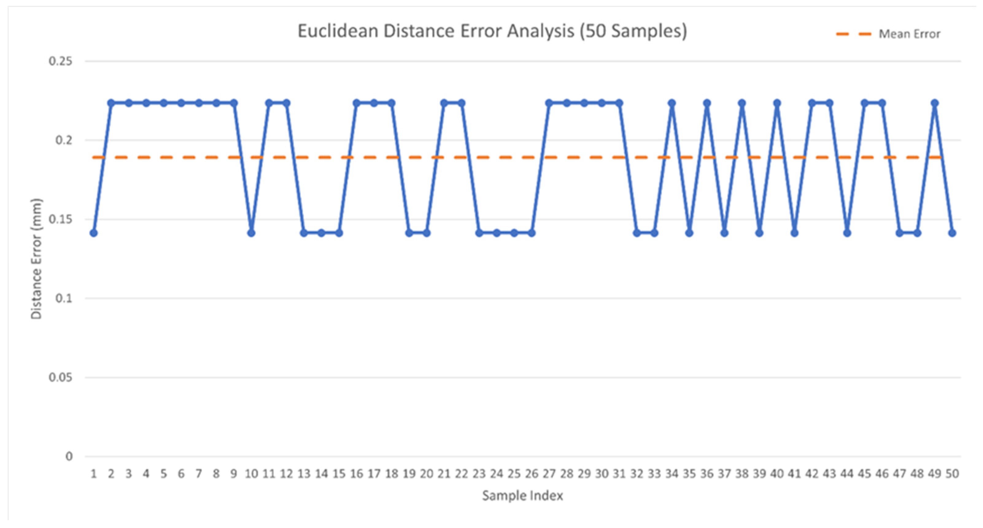
To verify the accuracy of the SCARA robot’s kinematic model, this study randomly selected 50 sets of discrete target points within the workspace for a displacement deviation testing experiment. The collected raw sample data are shown in Table 3. Fifty points were randomly selected within the camera’s field of view, with those near the edges excluded. Materials were then placed at these respective points for the robotic arm to grasp. To obtain more accurate measurement data, the Z-axis motion of the manipulator was initially excluded, and the coordinate points reached by the manipulator in each experiment were recorded. Finally, the static positioning accuracy of the system was comprehensively evaluated by comparing the target coordinates (x, y) calculated by the vision system with the actual coordinates (x′, y′) reached by the actuator.
Table 3.
Target positions and actual positions.
To comprehensively measure the position deviation, the Euclidean distance is introduced as the evaluation metric. The calculation formula is as follows:
where represents the sampled position vector error, (x, y) are the target coordinates, and (x′, y′) are the actual coordinates reached by the actuator.
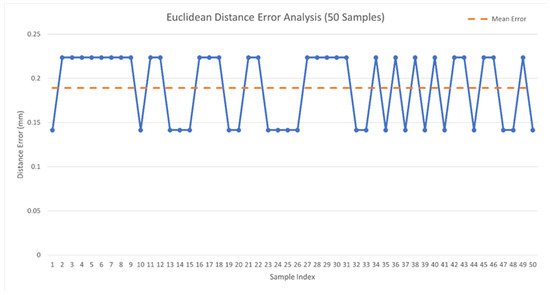
A line chart of the Euclidean distance error was generated based on the calculated Euclidean distances, as shown in Figure 18. According to the chart, average positioning error of this SCARA manipulator system is 0.189 mm (with a standard deviation of 0.028 mm). Observing the fluctuation range, the errors of all sampling points are strictly controlled between 0.141 mm and 0.223 mm. Considering the dimensions and grasping tolerances of the materials processed by this experimental platform, this sub-millimeter level average error ensures that the end-effector can reliably accomplish the target material capturing and placement tasks.
Figure 18.
Euclidean distance error.
7. Discussion
The proposed modular 4-DOF SCARA platform demonstrates high effectiveness in vision-guided sorting tasks, offering an interpretable “perception–decision–execution” workflow suitable for robotics education. By integrating a hierarchical control architecture—where a host terminal handles complex vision processing while a lower-level controller manages real-time joint coordination via CAN bus—the system achieves a high degree of modularity and scalability. Furthermore, the Webots-based digital twin serves as a critical validation bridge; its high fidelity (joint deviation < 0.5°) allows for pre-verifying singularity avoidance and smoothness through joint-space quintic polynomial interpolation before hardware deployment.
A core contribution of this work is the collaborative perception strategy that decouples classification from localization. By leveraging a lightweight YOLOv8 model for robust category identification and traditional geometric algorithms (HSV filtering and Hough circle transform) for sub-pixel centroid extraction, the system achieves an average recognition accuracy of 98.1%. This hybrid approach is bridged by a rigorous nine-point hand–eye calibration model, ensuring precise mapping from pixel coordinates to the physical workspace. Notably, the TPU-based compliant gripper acts as a hardware-level error absorber, successfully compensating for minor perception-to-mapping residuals and enhancing the overall grasp robustness across diverse material geometries.
From a system-level perspective, the recorded performance metrics—including a 96% communication success rate and an average positioning error of 0.189 mm—validate the reliability of the integrated software-hardware design. The observed perception cycle (4.5–6.5 s) is a deliberate design choice to ensure sub-pixel stability through a 30–50 frame averaging buffer, while the “0-s” logs in experimental data serve as robust error-abort flags to prevent faulty operations. These mechanisms collectively ensure the operational stability required for both laboratory training and potential industrial lightweight sorting scenarios. Moreover, from a cost-effectiveness perspective, the proposed platform significantly reduces both hardware and software investment compared with conventional commercial robotic teaching cells. On the hardware side, it adopts modular mechanical connections, a 3D-printed TPU compliant gripper, a consumer-grade depth camera, and a lightweight CAN-based distributed architecture, thereby lowering manufacturing, replacement, and maintenance costs. On the software side, the system relies entirely on open-source tools (Webots, YOLOv8, and OpenCV), avoiding commercial licensing expenses while maintaining straightforward deployment and customization for laboratory environments. Despite this reduced cost profile, the platform still achieves 98.1% recognition accuracy and a 0.189 mm positioning error, demonstrating a favorable balance between performance, reproducibility, and affordability for teaching and research applications.
Despite its performance, several limitations provide directions for future work. First, the spatial localization still partially relies on hand-tuned HSV thresholds, which are sensitive to drastic lighting changes. Second, while the nine-point calibration effectively handles planar mapping, expanding to comprehensive 3D spatial calibration would enhance versatility. Finally, although the collaborative strategy and soft gripper empirically improved success rates, future studies should include rigorous quantitative ablation tests—comparing pure deep learning regression with our hybrid approach—to precisely delineate the performance gains and compensation bounds of each module.
8. Conclusions
This study successfully implemented a modular 4-DOF SCARA visual sorting platform that addresses the need for cost-effective, transparent educational robotic systems. By proposing a collaborative perception strategy—integrating a lightweight YOLOv8 model for category classification with HSV filtering, Hough circle detection, and a nine-point hand–eye calibration model for spatial localization—the system achieved a robust average recognition accuracy of 98.1% under varying operational conditions. At the motion control layer, the application of a joint-space quintic polynomial interpolation algorithm effectively guaranteed continuous trajectories and circumvented Cartesian singularities, yielding a highly precise mean end-effector positioning error of just 0.189 mm. Furthermore, physical experiments validated that the mechanical compliance of the custom TPU soft gripper successfully absorbs minor perception-to-control mapping deviations, ensuring a stable overall sorting process with an average communication efficiency of 1.95 s per cycle. Ultimately, this hardware–software co-design approach provides a scalable, rigorously validated testbed for “New Engineering” education, while offering valuable empirical data and architectural references for industrial-grade sorting applications.
Author Contributions
Conceptualization, H.J., C.S. and X.J.; Methodology, T.L. and X.J.; Software, C.S. and Y.L.; Validation, Y.L.; Data curation, T.L., Y.L., F.G. and K.H.; Writing—original draft, H.J.; Writing—review and editing, X.J.; Visualization, T.L., F.G. and X.J.; Supervision, F.G., K.H. and X.J.; Project administration, K.H. and X.J.; Funding acquisition, K.H. and X.J. All authors have read and agreed to the published version of the manuscript.
Funding
This work was supported by the Weifang Science and Technology Development Plan Project (Grant No. 2024ZJ1097).
Data Availability Statement
The raw data supporting the conclusions of this article will be made available by the authors on request.
Conflicts of Interest
The authors declare no conflicts of interest.
References
- Carter, G.; Tokhi, M.O.; Oumar, O.A. Visual Control of a Robotic Arm. In Proceedings of the 22nd International Conference on Climbing and Walking Robots (CLAWAR), Kuala Lumpur, Malaysia, 26–28 August 2019; pp. 1–4. [Google Scholar]
- Bouzoualegh, S.; Guechi, E.; Zemir, Y. Model Predictive Control of a Three Degrees of Freedom Manipulator Robot. In Proceedings of the IC_ASET 2019, Hammamet, Tunisia, 19–22 March 2019; pp. 84–89. [Google Scholar]
- Zhang, M.; Gao, X.; Yin, L.; Wang, J. Design of robotic arm grasping system based on machine vision. Comput. Eng. Appl. 2024, 41, 22–27. (In Chinese). Available online: https://d.wanfangdata.com.cn/periodical/ChdQZXJpb2RpY2FsQ0hJU29scjlRdWljaxIRanNqeXl5cmoyMDI0MDgwMDUaCHY2bGtpczRv (accessed on 23 May 2025). [CrossRef]
- Laratta, L. Computer Vision-Based Robotics for the Automation: Simulation and Control of a Robotic Arm in the Automotive Field. Master’s Thesis, University of Padova, Padova, Italy, 2022. [Google Scholar]
- Kang, H.C.; Lee, H.J.; Kim, H.S. HSV Color-Space-Based Automated Object Localization for Robot Grasping without Prior Knowledge. Appl. Sci. 2021, 11, 7593. [Google Scholar] [CrossRef] [Scilit]
- Ngo, H.Q.T.; Nguyen, T.V.; Tran, T.B. Using an HSV-based approach for detecting and grasping an object by the industrial manipulator system. FME Trans. 2023, 51, 512–520. [Google Scholar] [CrossRef] [Scilit]
- Riadi, M.P.; Subairi; Gumilang, Y.S.A. Implementation of Object Detection by Color in HSV Space on Robot Arm. J. Electr. Syst. Comput. Eng. 2024, 8, 155–165. [Google Scholar]
- Lv, Z.; Cai, L.; Cheng, K.; Gao, X.; Wang, X. Target detection algorithm for robotic arm grasping system based on angle estimation. J. Sichuan Univ. Sci. Eng. (Nat. Sci. Ed.) 2023, 36, 46–56. (In Chinese). Available online: https://d.wanfangdata.com.cn/periodical/ChdQZXJpb2RpY2FsQ0hJU29scjlRdWljaxISc2NxaGd4eXhiMjAyMzAyMDA2GggxdjJhcTd0Zg%3D%3D (accessed on 23 May 2025). [CrossRef]
- Sun, C.; Hu, Z.; Peng, L.; Ye, Z.; Ding, J. Research on rapid path planning and hand-eye calibration of a 6-DOF robotic arm. Mech. Manag. Dev. 2025, 2, 48–56. (In Chinese). Available online: https://d.wanfangdata.com.cn/periodical/ChdQZXJpb2RpY2FsQ0hJU29scjlRdWljaxIQenpqc3lqYzIwMjUwMjAwNxoIeXFqaWdpeGY%3D (accessed on 23 May 2025). [CrossRef]
- Ma, Q.; Li, H.; Chirikjian, G.S. New probabilistic approaches to the ax = xb hand-eye calibration without correspondence. In Proceedings of the IEEE International Conference on Robotics and Automation (ICRA), Stockholm, Sweden, 16–21 May 2016; pp. 4365–4371. [Google Scholar]
- Zhang, A.; Zhang, K.; Yao, Y. Solving the robot-world hand-eye (s) calibration problem with iterative methods. Mach. Vis. Appl. 2017, 28, 569–590. [Google Scholar] [CrossRef] [Scilit]
- Koide, K.; Menegatti, E. General hand-eye calibration based on reprojection error minimization. IEEE Robot. Autom. Lett. 2019, 4, 1021–1028. [Google Scholar] [CrossRef] [Scilit]
- Wang, X.; Song, H. One-step solving the hand-eye calibration by dual kronecker product. J. Mech. Robot. 2024, 16, 101008. [Google Scholar] [CrossRef] [Scilit]
- Wu, J.; Liu, M.; Zhu, Y.; Zou, Z.; Dai, M.-Z.; Zhang, C.; Jiang, Y.; Li, C. Globally optimal symbolic hand-eye calibration. IEEE/ASME Trans. Mechatron. 2020, 26, 1369–1379. [Google Scholar] [CrossRef] [Scilit]
- Zhou, Z.; Ma, L.; Liu, X.; Cao, Z.; Yu, J. Simultaneously calibration of multi hand-eye robot system based on graph. IEEE Trans. Ind. Electron. 2024, 71, 5010–5020. [Google Scholar] [CrossRef] [Scilit]
- Li, L.; Wan, L.; Krueger, V.; Zhang, X. 3D Hand-Eye Calibration for Collaborative Robot Arm: Look at Robot Base Once. In Proceedings of the 22nd International Conference on Informatics in Control, Automation and Robotics, Marbella, Spain, 20–22 October 2025; pp. 333–341. [Google Scholar]
- Đalić, V.; Jovanović, V.; Marić, P. Submillimeter-accurate markerless hand-eye calibration based on a robot’s flange features. Sensors 2024, 24, 1071. [Google Scholar] [CrossRef] [Scilit]
- Cheng, Q.; Pan, F.; Yuan, Y. Hand-eye calibration method for gantry robot based on 3D vision sensor. Opt. Precis. Eng. 2021, 48, 200239. [Google Scholar] [CrossRef]
- Zhu, D.; Wu, H.; Ding, T.; Hua, L. Point cloud registration-enabled globally optimal hand-eye calibration. IEEE/ASME Trans. Mechatron. 2024, 29, 1824–1835. [Google Scholar] [CrossRef] [Scilit]
- Du, H.; Song, G.; Zhao, Y.; Han, J. A hand-eye calibration method for robotic arm and RGB-D camera using a 3D printed calibration sphere. Robot 2018, 40, 835–842. (In Chinese). Available online: https://d.wanfangdata.com.cn/periodical/ChdQZXJpb2RpY2FsQ0hJU29scjlRdWljaxIManFyMjAxODA2MDA4Gggya3BiMm5vOA%3D%3D (accessed on 23 May 2025). [CrossRef]
- Hong, Z.; Li, Z.; Han, H. Generative adversarial networks for solving hand-eye calibration without data correspondence. IEEE Robot. Autom. Lett. 2025, 10, 2494–2501. [Google Scholar] [CrossRef] [Scilit]
- Zhao, Y.; Yang, J.; Liu, D.; Yao, L.; Gao, W. Hand-eye calibration of a robotic arm based on SSA-BP neural network. Equip. Manuf. Technol. 2024, 11, 18–22. (In Chinese). Available online: https://d.wanfangdata.com.cn/periodical/ChdQZXJpb2RpY2FsQ0hJU29scjlRdWljaxIPenp5emRoMjAyNDExMDAzGgh6NzFiOWppZA%3D%3D (accessed on 23 May 2025). [CrossRef]
- Zhang, H.; Wang, X.; Zhang, Y. A simple calibration method for hand-eye vision system based on homography matrix. Comput. Eng. 2018, 44, 33–37. (In Chinese). Available online: https://d.wanfangdata.com.cn/periodical/ChdQZXJpb2RpY2FsQ0hJU29scjlRdWljaxIOanNqZ2MyMDE4MDkwMDYaCGxvdGMzamI4 (accessed on 23 May 2025).
- Mao, C.; Yu, R.; Song, A. A depth camera hand-eye calibration method combined with TCP calibration. Chin. J. Sci. Instrum. 2023, 44, 280–286. (In Chinese). Available online: https://d.wanfangdata.com.cn/periodical/ChdQZXJpb2RpY2FsQ0hJU29scjlRdWljaxINeXF5YjIwMjMwMzAzMRoIaDg2bWFxbTg%3D (accessed on 23 May 2025). [CrossRef]
- Qiao, F.; Miao, H.; Ji, H.; Zhang, W.; Su, H. Research on hand-eye calibration method of industrial robotic arm oriented to digital twin. Mach. Tool Hydraul. 2023, 51, 30–35. (In Chinese). Available online: https://d.wanfangdata.com.cn/periodical/ChdQZXJpb2RpY2FsQ0hJU29scjlRdWljaxIOamN5eXkyMDIzMDEwMDYaCDltbmV5ZGE2 (accessed on 23 May 2025).
- Wang, B.; Wang, X.; Ma, Z.; Liang, W. A hand-eye calibration method based on target recognition in robotic arm live-line work. Electr. Power Inf. Technol. 2021, 19, 68–74. (In Chinese). Available online: https://d.wanfangdata.com.cn/conference/ChNDb25mZXJlbmNlTmV3U1F1aWNrEggxMTAxNjI3NhoIbTFlYWdjNDQ%3D (accessed on 23 May 2025).
- Allegro, D.; Terraran, M.; Ghidoni, S. Multi-camera hand-eye calibration for human-robot collaboration in industrial robotic workcells. IEEE Robot. Autom. Lett. 2024, 9, 9852–9859. [Google Scholar] [CrossRef] [Scilit]
- Yang, W.; Sha, L.; Fan, D.; Zhang, H.; Bai, J. Hand-eye calibration optimization method for blade repair robot based on abnormal sample detection. Opt. Precis. Eng. 2025, 52, 40–53. (In Chinese). Available online: https://d.wanfangdata.com.cn/periodical/ChdQZXJpb2RpY2FsQ0hJU29scjlRdWljaxINZ2RnYzIwMjUwMzAwNBoIcThtZGVuZnQ%3D (accessed on 23 May 2025). [CrossRef]
- Gao, J.; Liang, D.; Chen, Y. Hand-eye calibration method for line laser profile scanning robot based on a standard cylinder. Robot 2022, 44, 321–332. (In Chinese). Available online: https://d.wanfangdata.com.cn/periodical/ChdQZXJpb2RpY2FsQ0hJU29scjlRdWljaxIManFyMjAyMjAzMDA3Ggh5enA3dnNmdg%3D%3D (accessed on 23 May 2025). [CrossRef]
- Yuan, J.; Chen, Q.; Liu, L.; Zhang, Y.; Zhai, J. Structural analysis and motion planning of heterogeneous six-axis robotic arm. Equip. Manuf. Technol. 2025, 9, 78–84. (In Chinese). Available online: https://d.wanfangdata.com.cn/periodical/ChdQZXJpb2RpY2FsQ0hJU29scjlRdWljaxIPenp5emRoMjAyNTA5MDA5Ggg3bG9hNHQyOA%3D%3D (accessed on 23 May 2025). [CrossRef]
- Shi, W.; Ma, Z.; Liu, Z. Design, kinematics research and trajectory planning of refueling robot manipulator. J. Chongqing Univ. Technol. 2015, 10, 80–84. (In Chinese). Available online: https://d.wanfangdata.com.cn/periodical/ChdQZXJpb2RpY2FsQ0hJU29scjlRdWljaxIPc2NiZ3hiMjAxNTEwMDIxGggzeW9idWJ0aA%3D%3D (accessed on 23 May 2025). [CrossRef]
- Ma, Y.; Zeng, T.; Jiang, H. Kinematics analysis and trajectory planning of robotic arm based on MATLAB. Packag. Eng. 2023, 44, 187–193. (In Chinese). Available online: https://d.wanfangdata.com.cn/periodical/ChdQZXJpb2RpY2FsQ0hJU29scjlRdWljaxINYnpnYzIwMjMwMzAyMxoIYW1mYXRsNTY%3D (accessed on 23 May 2025). [CrossRef]
- Fan, Y. Simulation research on path planning of robotic arm based on improved RRT algorithm. Mod. Mach. 2024, 13, 4674–4680. (In Chinese). Available online: https://d.wanfangdata.com.cn/periodical/ChdQZXJpb2RpY2FsQ0hJU29scjlRdWljaxIQcWszXzAwMDAzMTUyNTMyNBoIaXN3OTJmdWs%3D (accessed on 23 May 2025). [CrossRef]
- Zhang, H.; Ge, H.; Li, J.; Cheng, W.; Li, W. Trajectory planning and simulation of robotic arm based on SA-IPSO. Mech. Manag. Dev. 2024, 10, 57–64. (In Chinese). Available online: https://d.wanfangdata.com.cn/periodical/ChdQZXJpb2RpY2FsQ0hJU29scjlRdWljaxIQenpqc3lqYzIwMjQxMDAwORoINHF2enQzZXM%3D (accessed on 23 May 2025). [CrossRef]


Disclaimer/Publisher’s Note: The statements, opinions and data contained in all publications are solely those of the individual author(s) and contributor(s) and not of MDPI and/or the editor(s). MDPI and/or the editor(s) disclaim responsibility for any injury to people or property resulting from any ideas, methods, instructions or products referred to in the content. |
© 2026 by the authors. Published by MDPI on behalf of the International Institute of Knowledge Innovation and Invention. Licensee MDPI, Basel, Switzerland. This article is an open access article distributed under the terms and conditions of the Creative Commons Attribution (CC BY) license.