


Abstract
Evaluating the behavior of materials and their response under low-velocity dynamic impact (less than 30 m/s) is a challenging task in various industries. It requires customized test methods to replicate real-world impact scenarios and capture important material responses accurately. This study introduces a novel spring-actuated testing setup for low-velocity impact (LVI) scenarios, addressing the limitations of existing methods. The setup provides tunable parameters, including adjustable impactor mass (1 to 250 kg), velocity (0.1 to 32 m/s), and spring stiffness (100 N/m to 100 kN/m), allowing for flexible simulation of dynamic impact conditions. Validation experiments on steel plates with a support span of 800 mm and thickness of 5 mm demonstrated the system’s satisfactory accuracy in measuring impact forces (up to 714.2 N), displacements (up to 40.5 mm), and velocities. A calibration procedure is also explored to estimate energy loss using numerical modeling, further enhancing the test setup’s precision and utility. The results underline the effectiveness of the proposed experimental setup in capturing material responses during low-velocity impact events.
1. Introduction
The analysis of mechanical behavior and the evaluation of durability and resilience under dynamic impact loads is an essential process in various industries (e.g., aerospace, glazing, security, and automotive) [1,2]. Dynamic impact scenarios are generally categorized based on the velocity and mass of the impacting body [3]. Specifically, these are low-velocity impacts, intermediate-velocity impacts, ballistic or high-velocity impacts, and hyper-velocity impacts. These categories range from velocities below 10 m/s for low-velocity impacts, 50 m/s to 1000 m/s for intermediate-velocity impacts, 1 km/s to 2 km/s for ballistic impacts, and 2 km/s to 5 km/s for hyper-velocity impacts [4]. This classification is an important basis for understanding the energy transfer from the projectile to the target, the energy dissipation, and the damage propagation mechanisms that define these different impact scenarios.
Given its unique characteristics, low-velocity impact (LVI) requires a critical assessment among these impact categories. LVI scenarios, such as accidental collisions with birds during aircraft take-off and landing, hailstorms, or tools accidentally falling on structures [5,6], can be particularly hazardous due to the subtlety of the damage inflicted, which may not be immediately apparent after impact [5]. The underlying hazard lies in the fact that the structural defects caused by LVI can be difficult to detect [7]. This is exacerbated by the prolonged duration of the impact, leading to a dynamic structural response in a larger region [8].
Various test procedures have been developed to understand the responses to low-velocity impacts [9]. Experimental methods used for this purpose lack standardized criteria and usually employ custom designs with user-defined requirements [10,11]. Available testing techniques for LVI include the Izod and Charpy technique [12,13,14], which is used to evaluate the impact strength of materials. In addition, the drop-weight technique [15] is a method in which a mass is lifted to a certain height before it is released, causing an impact on the specimen. In the pendulum impact method, a certain weight is suspended from a rope or rod so that it reaches a certain velocity after being released from a certain height [16]. In the shock tube technique, on the other hand, compressed air or a liquid is suddenly released in a channel and a certain weight is thrown at the sample at a certain velocity [17,18,19]. A summary of these techniques can be found in Table 1 [17,18,19]. A discussion of these techniques is given in Table 1.
Table 1.
Low-Velocity Impact Testing Techniques.
Variations and modifications of the above impact test methods have been developed to increase the adaptability and mitigate the limitations of these methods [8]. In 2002, a multipurpose testing system capable of applying mechanical energy to specimens using a two-carriage compression setup was introduced [25]. Its versatility allows for the testing of different materials, but the complexity of the setup necessitates calibration for different samples and materials. In contrast, Guanqun et. al. developed a horizontal impact test rig equipped with load-bearing platforms and sliding supports [26]. While suitable for horizontal impact testing, altering the impact parameters to capture various impact scenarios is challenging. In addition, a test system utilizing a ball screw mechanism to accelerate a carriage and allow precise control of acceleration has been proposed [27]. However, the maintenance of the ball screw mechanism may pose challenges over time. Therefore, a simple setup for horizontal impact testing was introduced by Hidalgo et. al. using a pulley block for tensioning [28].
In a more recent study, Jason et. al. presented an inventive system that allows for adjustable acceleration, distance, and flexibility in impact tests [29]. However, it struggles to accurately replicate real-world conditions, especially in high-momentum LVI scenarios. One of the main challenges is to ensure the precision of the timing and magnitude of the impacts, as the system relies on gravity and inertial forces, which could affect test accuracy and repeatability. In addition, the complex assembly process and calibration requirements of the system may pose practical challenges for implementation and maintenance, especially in resource-constrained environments.
As a result, there is still a significant gap in existing methods for low-velocity impact testing. These include inadequate handling of impact load and support formation, inability to capture important data such as load–time profiles, limited versatility in accommodating different material and system experiments, and restrictive limitations on the interactions between weight, velocity, and impact area.
To overcome these challenges, this study develops a novel experimental setup tailored to evaluate the dynamic response of materials under low-velocity impacts. With its universal design, it provides enhanced adaptability through tunable parameters, including impactor weight, velocity, surface geometry, stiffness, specimen size, shape, and orientation, thus providing a versatile platform for testing various specimens in low-velocity impacts.
2. Design of Components and Fabrication
2.1. Experimental Setup
The investigation of material behavior under impact conditions and the evaluation of components manufactured from specific materials necessitate the utilization of various experimental techniques [30]. Dynamic impact testing setups, employing advanced instrumentation for accurate data acquisition, are critical for simulating various scenarios [31,32,33]. Conducted in controlled environments like ballistic ranges and drop towers, these tests utilize calibrated projectiles and surrogate targets to replicate real-world conditions [4,13]. Variables such as impact velocity, angle of incidence, and energy levels are carefully controlled, while efforts to achieve reproducibility and accuracy are essential. Analyzing stress–strain relationships, failure modes, and fracture patterns in the collected data provides valuable insights into material behavior, contributing to the development of enhanced materials and protective systems across diverse industries [34,35].
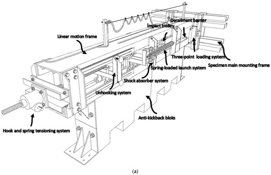
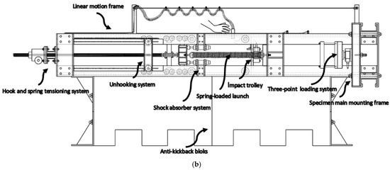
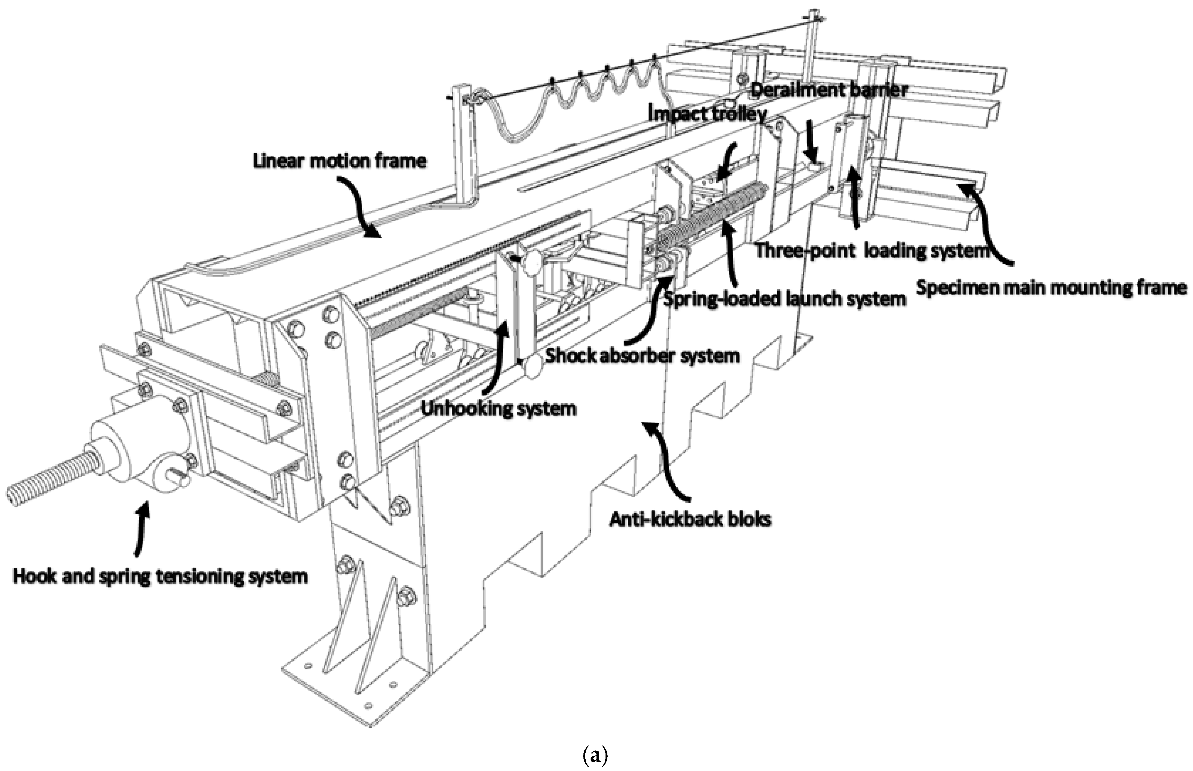
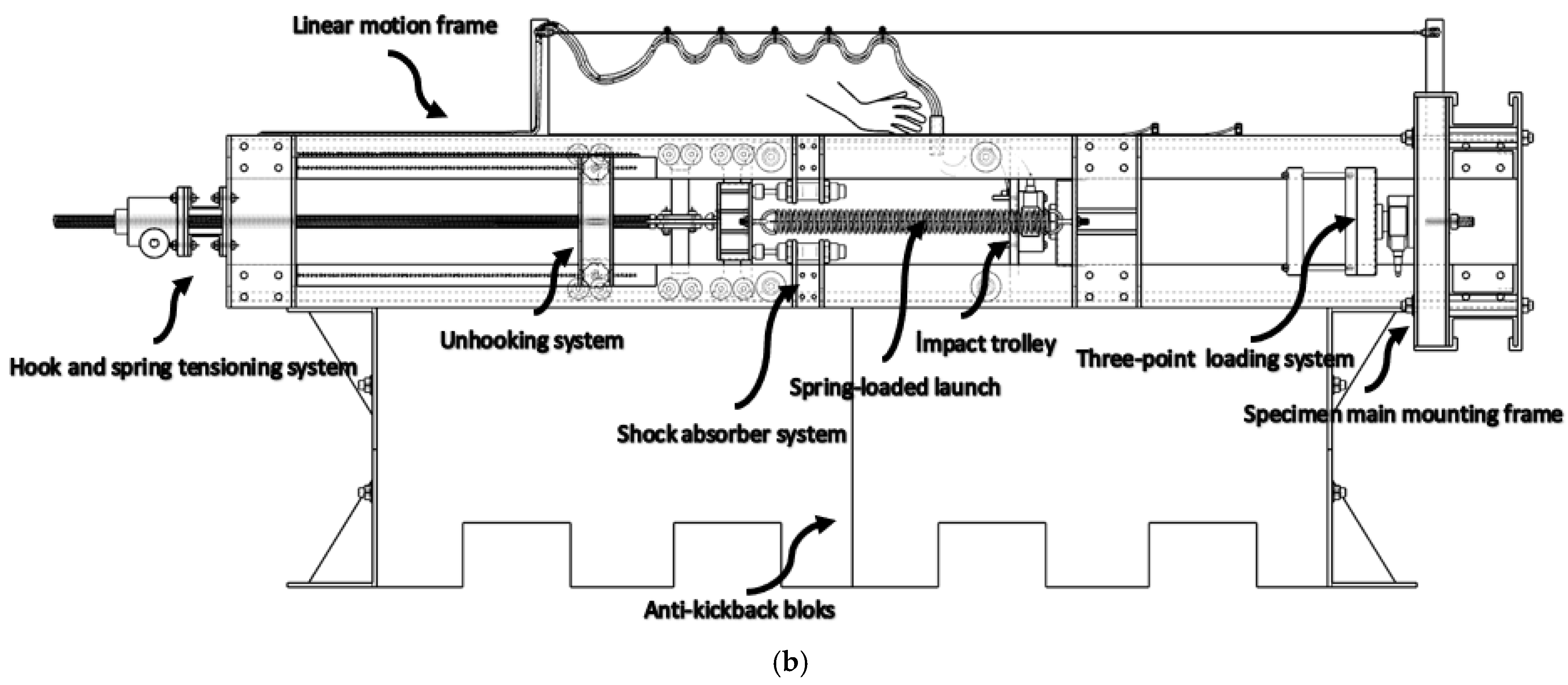
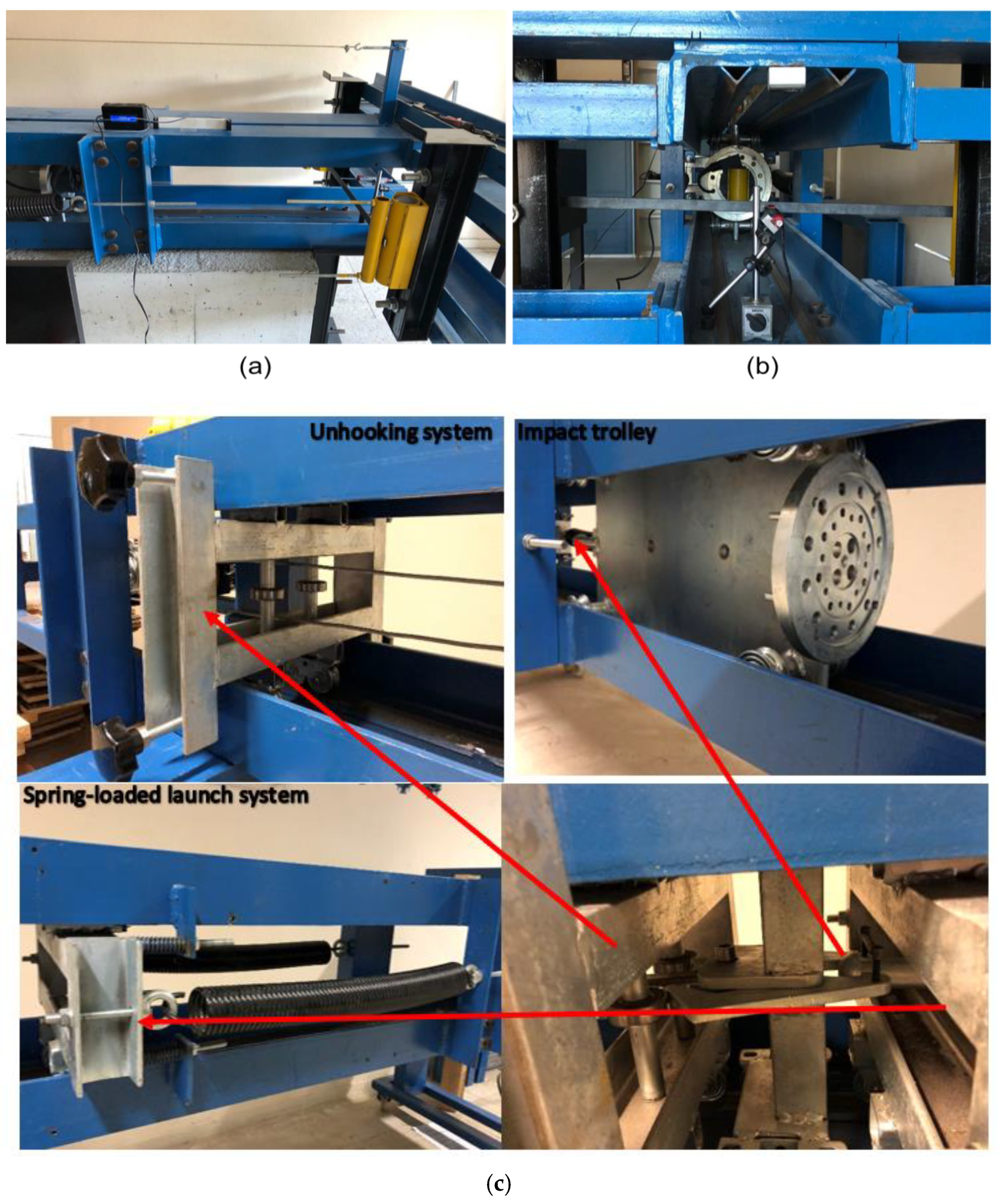
Despite advancements in dynamic impact testing, challenges remain in replicating real-world impacts and controlling all relevant variables. This study introduces a novel experimental device specifically designed to evaluate material response under low-velocity impacts (Figure 1, Table 2) [36]. The setup offers a broad range of tunable parameters, including impactor weight, velocity, surface geometry, and rigidity, enhancing flexibility for diverse test specimens.
Figure 1.
A schematic representation of the proposed dynamic impact testing setup: (a) isometric view; (b) side view.
Table 2.
Various parts in the impact test setup and their functions and components.
2.1.1. Key Parameters
The innovative spring-driven universal impact testing setup, as depicted in Figure 1, introduces a sophisticated experimental configuration with extensive adaptability. This configuration offers enhanced control over the main impact parameters—specifically, impact velocity (v) in meters per second (m/s) and impact energy (E) in joules (J). This control is facilitated by Equation (1), which relates the elastic potential energy stored in the tension springs to the kinetic energy, in which the fundamental variables are the spring constant (k) in newtons per meter (N/m), extension distance (x) in meters (m), and mass of the impactor (m) in kilograms (kg). Equation (1) serves as the bedrock for precise experimental control over the impact conditions.
2.1.2. Controllable Spring Material and Extension
To achieve a wide range of impact scenarios, the setup offers considerable flexibility in adjusting the spring extension and facilitating changes of the spring material and spring constant. This is accomplished through the implementation of two replaceable tension springs with variable spring constants (e.g., ranging from 100 N/m to 100 kN/m) [37]. By selecting different springs, the system’s stiffness can be modulated, and the impact response can be tailored accordingly. The extension distance of these tension springs is precisely regulated using an AC motor, enabling controlled variations in the extension (e.g., up to 80 cm).
2.1.3. Variable Impactor Mass
The mass of the impactor can be effectively altered to accommodate diverse testing requirements. The mass can be adjusted (1 to 250 kg) by adding or removing weights to the impactor carriage through dedicated weight attachment holes. This capability enables the simulation of a broad spectrum of impact conditions, encompassing scenarios from low-energy impacts to high-energy collisions.
2.1.4. Impact Energy and Velocity
The comprehensive control over these critical parameters ensures the ability to achieve desired impact velocities and energies. For instance, impact velocities can be varied (e.g., from 0.1 m/s to 32 m/s) to study the response of materials and structures under different loading rates. Correspondingly, impact energies can be adjusted (e.g., from 0.005 J up to 130,000 J) to investigate the material’s deformation behavior and structural integrity under varying impact energies.
2.1.5. Impactor Properties and Characteristics
Furthermore, the setup allows for the exploration of diverse impactor properties. By connecting impactors with different materials, hardness, shapes, surface geometries, and rigidities, the influence of these characteristics on the impact response can be investigated. For example, connecting impactors made of steel, aluminum, and composite materials with varying hardness and surface geometries (e.g., flat, conical, and hemispherical) enables a comprehensive study of material behavior during impact. A comprehensive summary of the various modifications that can be applied to the different parameters for specific testing scenarios is presented in Table 3.
Table 3.
The parameters and properties of the various setup components.
2.1.6. Versatile Sample Assemblies
Diverse sample assemblies are facilitated through the integration of the main sample mounting frames with the dynamic impactor frame. The gap on this frame offers flexibility in accommodating multiple sample mounting configurations. One illustrative instance of this mounting versatility is the implementation of a three-point loading system, which is employed in this study to subject sample steel plates to dynamic response testing under low-velocity impact conditions, through varying impact energies and velocities.
2.1.7. Operation and Reliability
The spring-driven launching system (Figure 1) ensures precise impacts by using tension springs, rail wheels, a pushing carriage, and connecting beams to launch the impact carriage at a predetermined velocity and energy. A synchronized hook and spring tensioning mechanism, with quick-release hooks and threaded jacks, provides controlled energy release for specific impact scenarios.
Accuracy is further improved by an adjustable tensioning system, allowing precise spring tension calibration. A shock-absorbing system halts the pushing carriage after impact initiation, ensuring consistent impact delivery. Additionally, exit barriers prevent accidental departure of the impact carriage, maintaining system reliability and experimental integrity.
2.2. Test Specimens
In this study, the dynamic response of steel plates was assessed under low-velocity impact conditions using a three-point loading system, highlighting the versatility of the experimental device in precisely tuning impact scenarios. A total of ten steel plates, each 5 mm thick and 20 mm wide, were tested. The plates measured 850 mm in length, with an 800 mm support span. The specimens conformed to EN 10025-2 S235JR (ST37) grade steel, which has a minimum yield stress of 235 MPa and an elastic modulus of 165 GPa, determined under quasi-static conditions. The chemical composition of this steel grade is listed in Table 4 [25]. This characterization provides a robust basis for analyzing the dynamic behavior of steel under varying impact conditions.
Table 4.
Chemical composition of steel grade EN10025-S235JR (ST37) [38].
2.2.1. Quasi-Static Testing
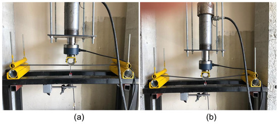
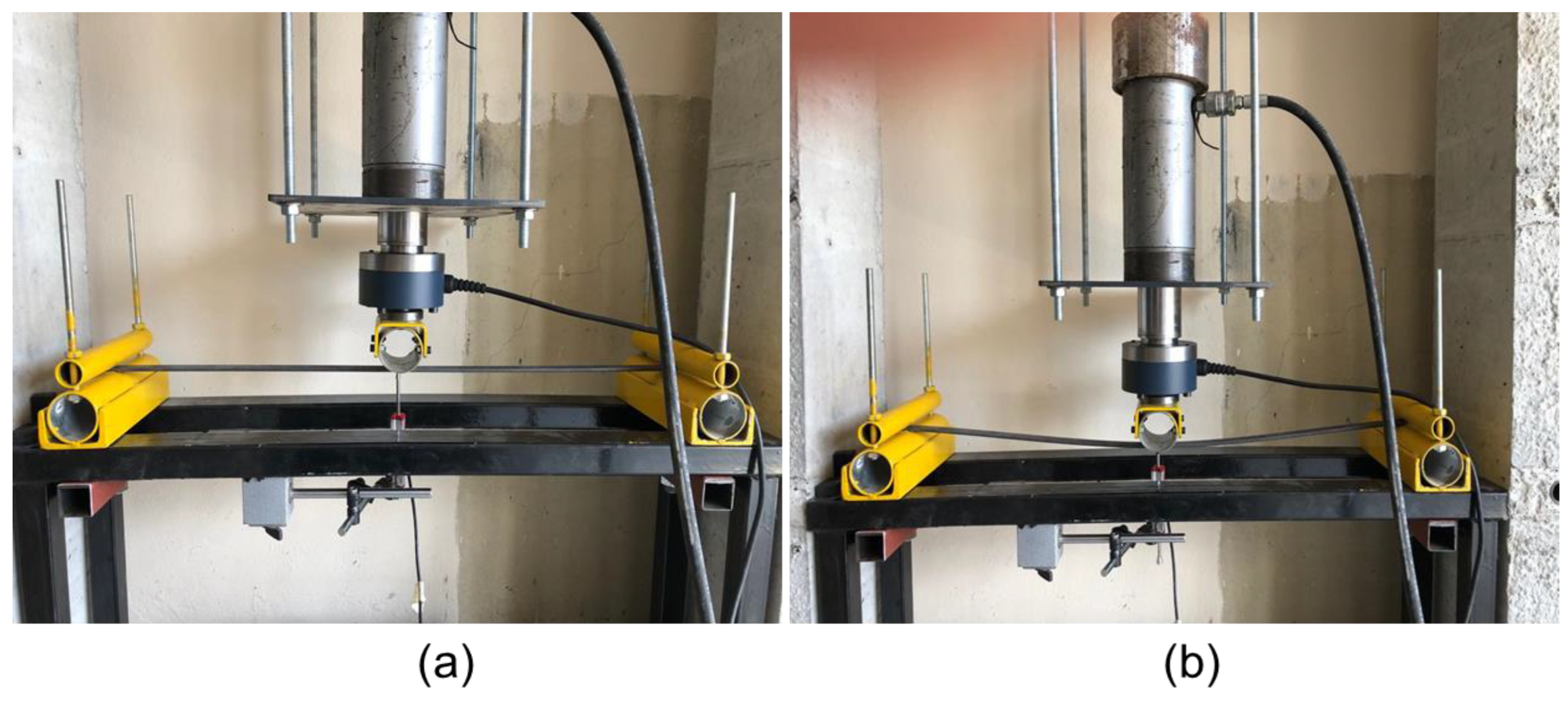
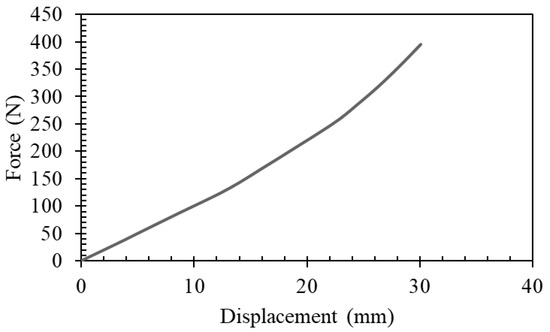
The control specimen, sharing identical size and material properties, underwent quasi-static testing using a three-point bending setup. The testing conditions mirrored those employed for dynamic impact assessments, ensuring consistency. The three-point bending test is illustrated in Figure 2. Subsequently, the force–displacement relationship is depicted in Figure 3.
Figure 2.
Testing the response of the control specimens under quasi-static testing (a) during testing and (b) after testing.
Figure 3.
The force–displacement response of the control specimens under quasi-static testing.
2.2.2. Dynamic Testing
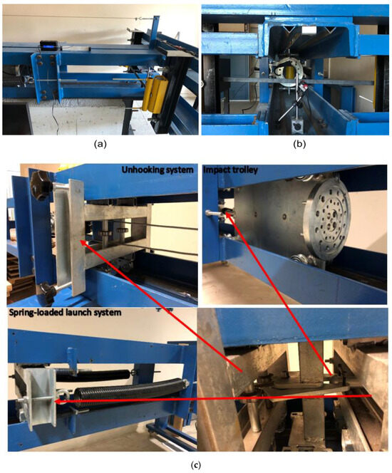
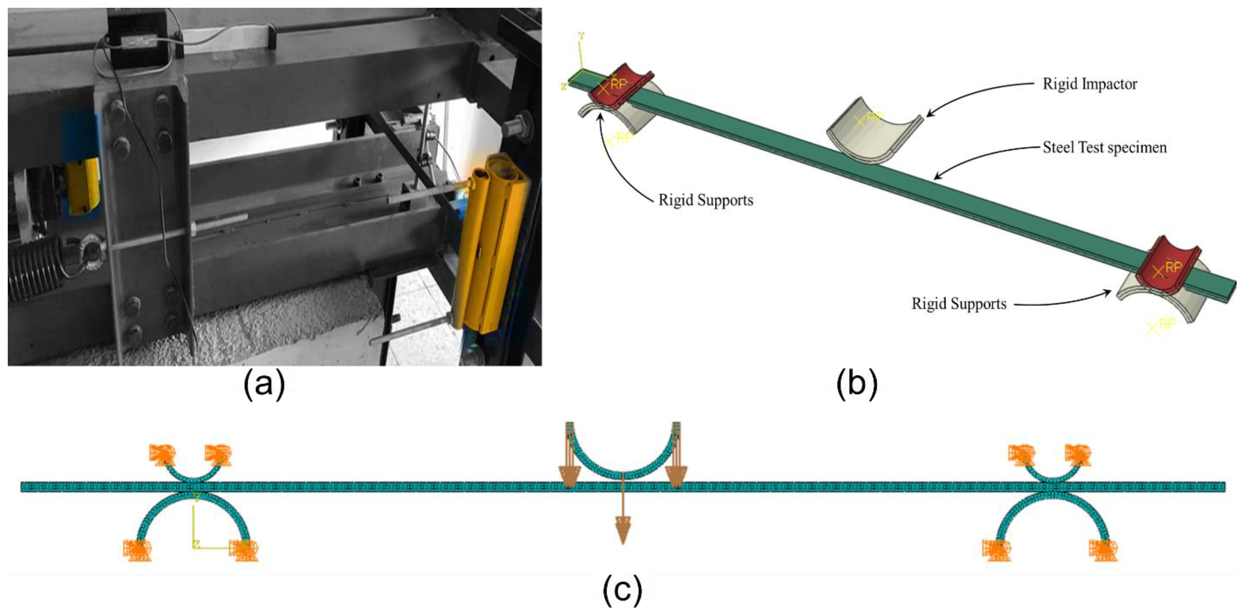
The dynamic impact testing setup, which included three-point bending specimens, is shown in Figure 4a,b. The system was designed to store potential energy by extending the springs, as depicted in Figure 4c. The same three-point bending frame, coupled with the dynamic impact setup, was used to test eight steel specimens, as summarized in Table 5. During testing, an AC motor applied tension to the springs supporting the impactor carriage, and, by varying the springs’ extension distance, impacts were generated at different energy levels across the specimens.
Figure 4.
The proposed dynamic impact testing setup: (a) side view; (b) the setup with the specimen installed; (c) impact test actuation system.
Table 5.
The experimental characteristics for the dynamic impact specimens.
Maximum impact force and displacement values were obtained from the time-dependent graphs discussed in Section 3.1. Specifically, these values were derived by analyzing the peak values on the force–time and displacement–time curves, ensuring an accurate representation of the material’s response under impact conditions.
To ensure accurate data collection, various sensors and instruments were integrated into the testing setup. A load sensor was incorporated into the impact carriage to measure the force–time history during impact events. Additionally, a velocity sensor and accelerometer were attached to the setup to record the impactor’s velocity and acceleration at the moment of impact. To record the response of the steel plates, displacement gauges were positioned on the tested specimen and a data acquisition system was employed.
2.3. Numerical Design
In this section, we further investigate the proposed spring-actuated dynamic impact setup using finite element modeling (FEM). This modeling serves to investigate any source of discrepancies that could potentially impact the accuracy of recreating numerically the results of a dynamic impact (e.g., the effects of system friction and air resistance). This process could highlight the potential energy losses in the physical system when compared to idealized numerical models.
Therefore, the eight dynamic impact scenarios (Table 5) were investigated using the FEM Abaqus/Explicit software-V22. The proposed simulation model is shown in Figure 5. The steel material was modeled as an elastic–plastic material with 5% damping and the mechanical properties listed in Table 6. The material properties adapted considered the high-strain rate of the impact.
Figure 5.
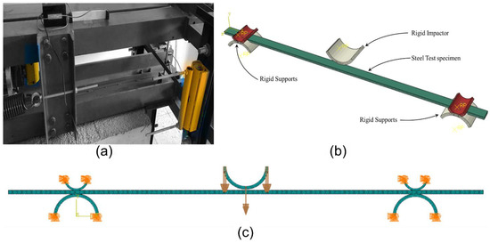
The proposed simulation model of the dynamic three-point bending testing setup: (a) 3-point testing apparatus attached to the setup; (b) implemented finite element model; and (c) applied boundary conditions.
Table 6.
The material definition implemented in numerical modeling [39].
The model specifically focuses on the interaction between the impactor and the steel specimen, excluding detailed representations of the railing and motion system. However, the numerical results were calibrated by incorporating an estimated friction coefficient of 0.37, derived from the experimental data of five specific specimens (IDs 2, 3, 5, 6, and 7) as listed in Table 5. Moreover, spring dynamics, including extension and potential energy, were not modeled since their influence ceases prior to impact. Instead, the impact energy was calculated from the impactor’s mass and velocity just before contact. This approach accurately captures the energy transfer during impact while simplifying the simulation.
The developed models were discretized using 4 × 4 mm S4R mesh elements with reduced integration (four-node doubly curved thin shell elements) [40]. This choice was made based on a mesh sensitivity analysis with mesh sizes from 2 × 2 mm to 6 × 6 mm to provide convergence with minimal computational cost. The thickness of the specimens was approximated using Simpson’s integration rule with seven integration points. The supports were modeled with discrete rigid shells, and the rotation of the specimens was allowed at the supports. Since the impactor sustained no damage during the experimental testing, it was modeled as a discrete rigid shell having the mass and initial velocity as per the testing conditions.
3. Results and Discussions
3.1. Experimental Results
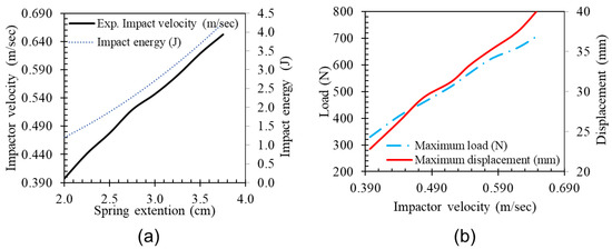
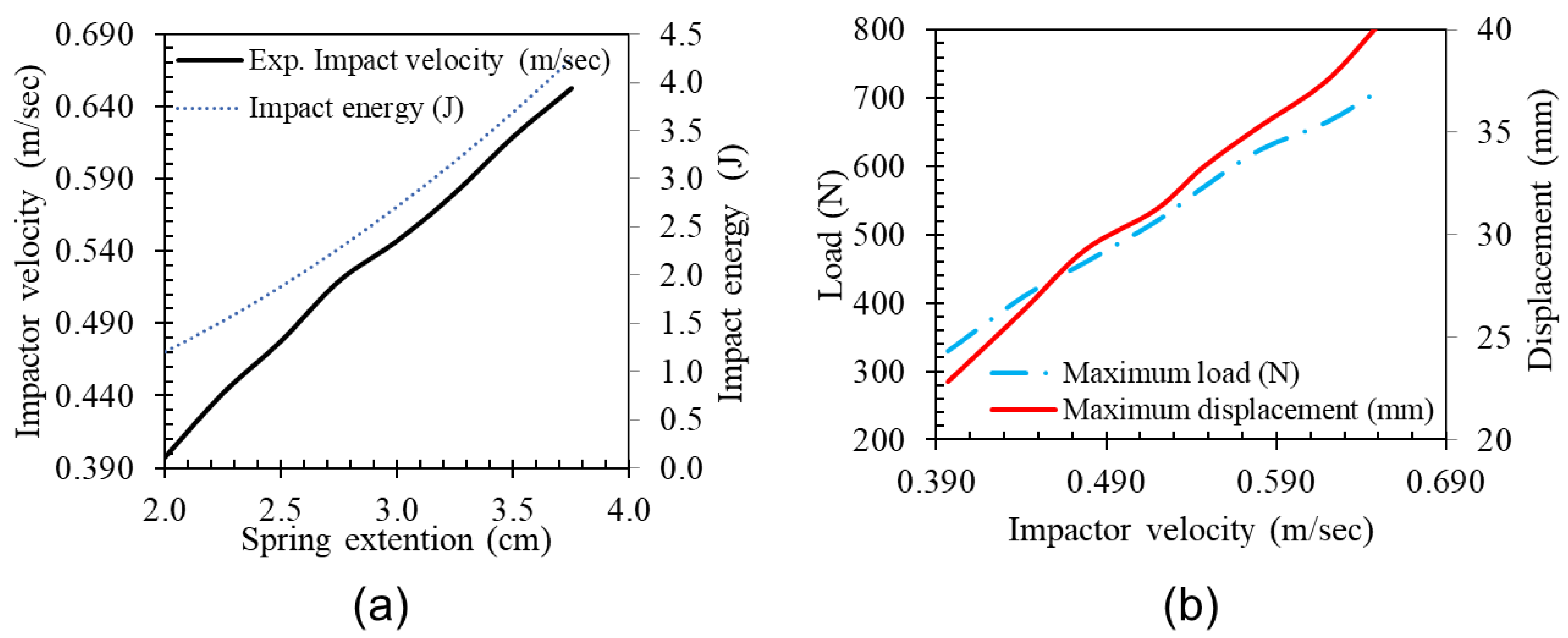
This section discusses the effect of varying key parameters on the specimen’s response using the spring-driven dynamic impact testing setup. The tensile spring extensions were incrementally adjusted for the eight steel specimens, as summarized in Table 5. As seen in Figure 6, increasing the spring tension increased impact velocity, force, and energy, along with the measured response of the impacted specimen.
Figure 6.
Tuning the tensile springs in the setup to generate (a) the impact velocity and energy for a given (b) load and displacement on the specimen.
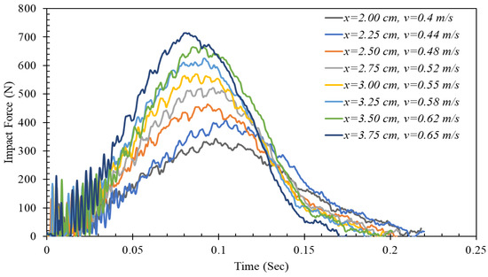
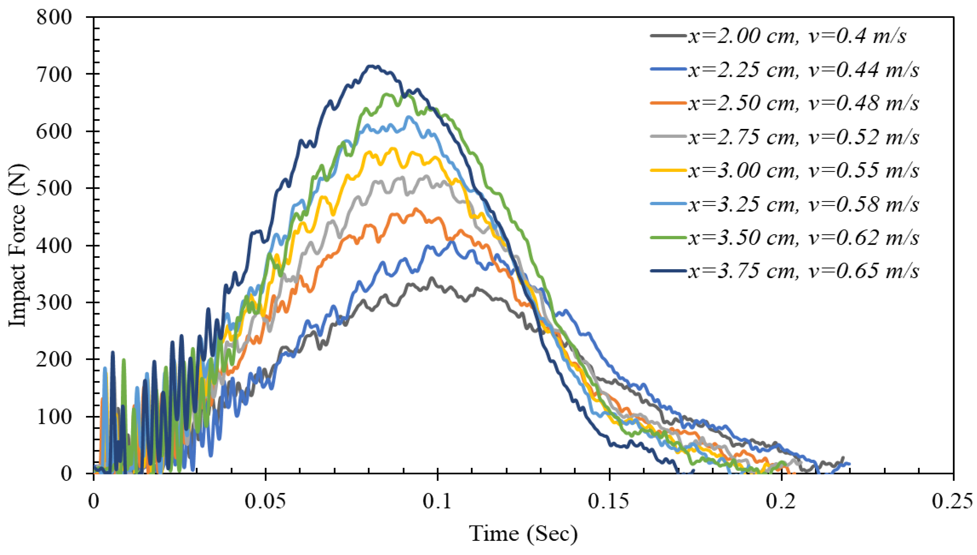
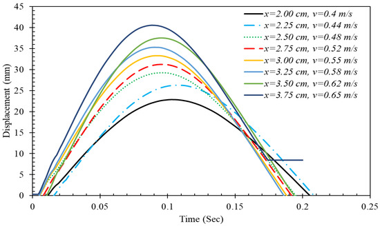
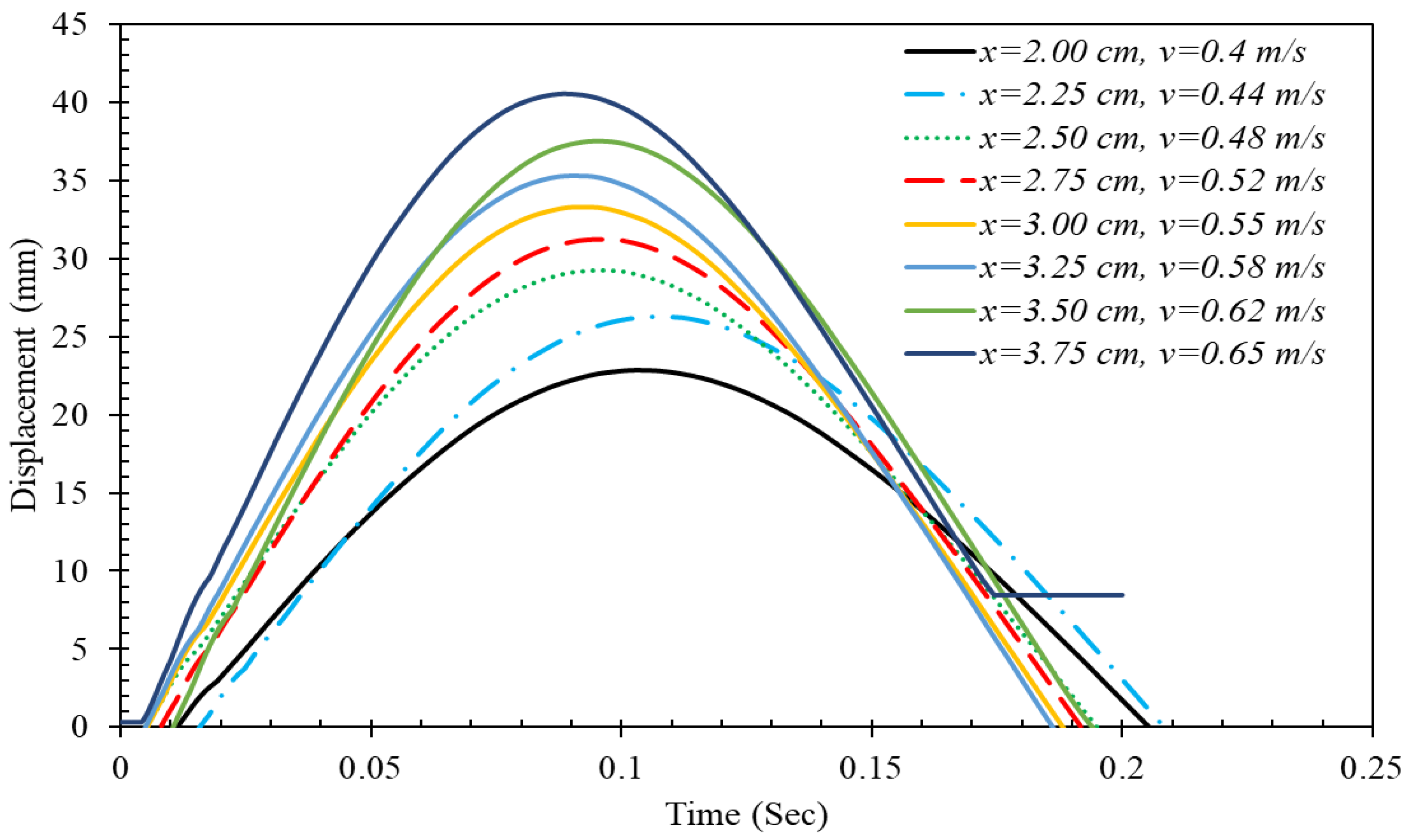
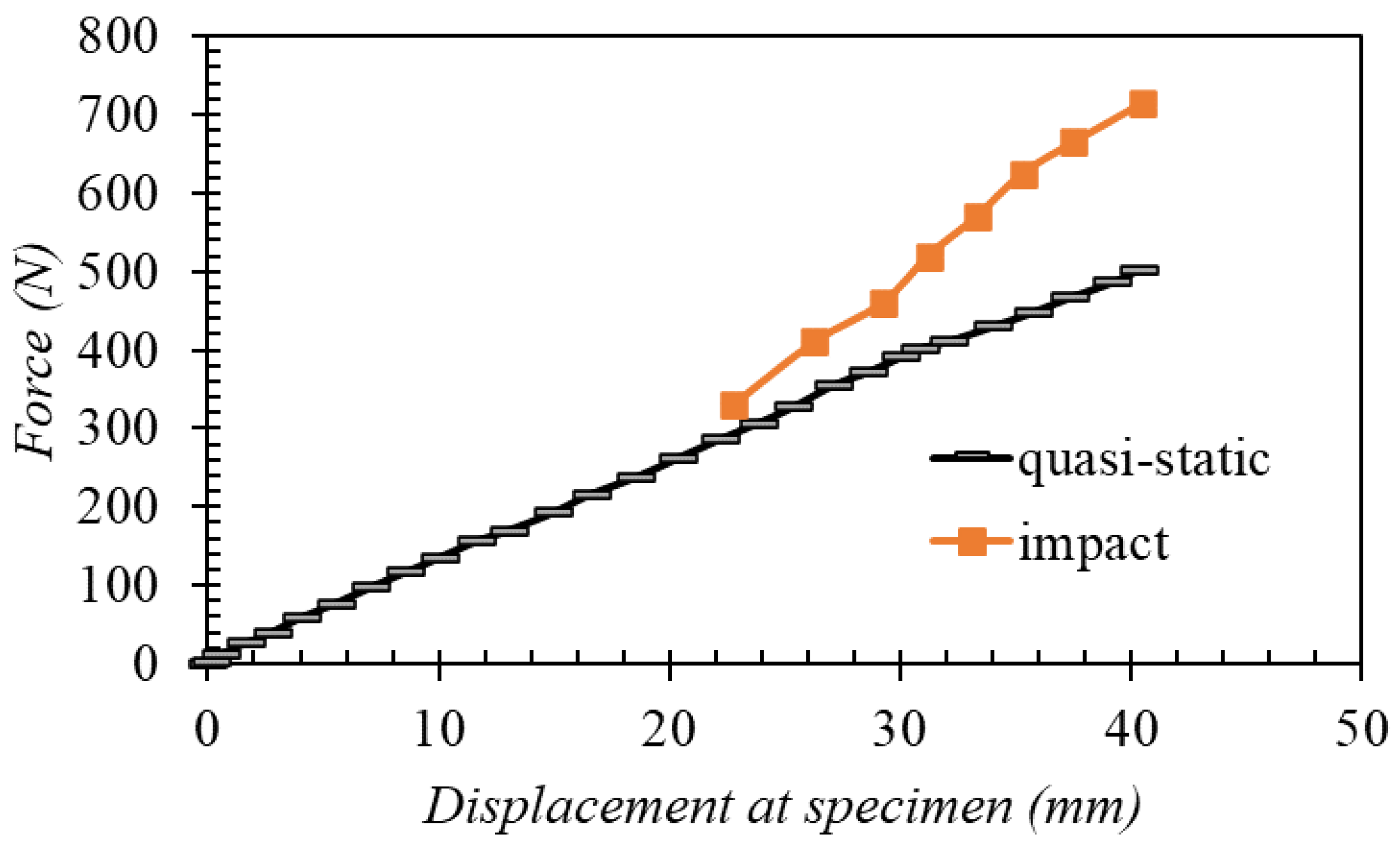
The dynamic impact force recorded at the mid-span of the steel specimens across various impact velocities is shown in Figure 7. The results indicate that higher impact velocities increase the impact force while reducing the duration of loading and strain rate. Displacement–time histories for the specimens, depicted in Figure 8, confirm that most specimens remained in the elastic zone, except for the specimen tested at 0.65 m/s. The transition from elastic to plastic behavior in this specimen is evident from the straight line in Figure 9, attributed to plastic strain and residual deformation.
Figure 7.
Impact force–time history for the dynamic impact testing.
Figure 8.
Displacement–time history for the dynamic impact testing.
Figure 9.
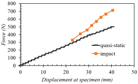
Force–mid-span displacement response of the dynamic impact and quasi-static testing.
The load–displacement behavior of the steel plate from both quasi-static and dynamic tests is presented in Figure 8. As the impact velocity increases, the difference between the dynamic impact load and the equivalent static load widens, highlighting the impact velocity’s influence on the material’s response. The developed testing device effectively captured the specimen’s response under varying impact velocities.
To ensure accuracy, an uncertainty analysis was conducted. Sources of uncertainty included material property variations, velocity and force measurement errors, and spring calibration. The combined standard uncertainty was calculated using the root-sum-square method, resulting in ±5% uncertainty for displacement measurements and ±7% for force measurements.
3.2. Numerical Results
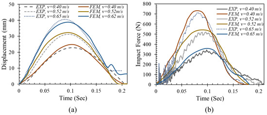
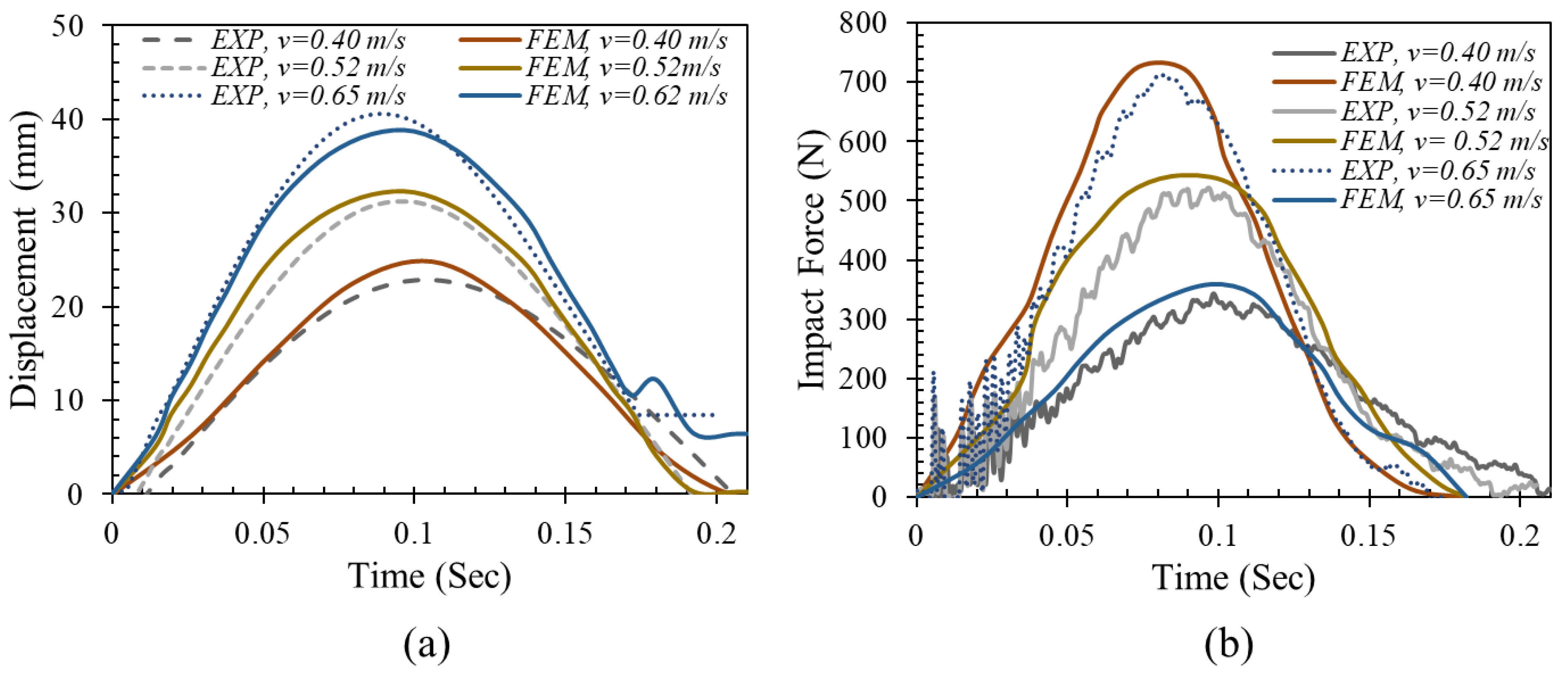
The results of the numerical modeling compared to the experimental results are shown in Figure 10. The comparison in Figure 9 illustrates the accuracy of the Finite Element Model (FEM) against the experimental (EXP) data for different impact velocities (v = 0.40 m/s, 0.52 m/s, and 0.65 m/s). The FEM results matched closely the experimental data, demonstrating the model’s ability to predict the dynamic response accurately. The modeling of the dynamic impact of the steel specimens managed to capture the impact and the resulting displacement with satisfactory accuracy. It is important to note that no fitting parameter was used in this comparison. Instead, the FEM was calibrated using initial experimental results to estimate the friction coefficient of the system. Once calibrated, the FEM was applied to predict the impact responses shown in Figure 9 without further adjustments, ensuring an unbiased comparison. It should be noted also that the numerical modeling served the rule of calibrating the setup by estimating the friction of the railing and motion system. This was achieved by devoting the results of the five specimens with IDs 2,3,5,6, and 7 as per Table 5, for the calibration of the results. Based on this calibration procedure, the friction coefficient of the built setup was estimated to be 0.37.
Figure 10.
A comparison of the measured and predicted (a) mid-span displacements and (b) impact forces.
The numerical modeling results, compared with the experimental data, are presented in Figure 10. The Finite Element Model (FEM) accurately predicted the dynamic response for different impact velocities (0.40 m/s, 0.52 m/s, and 0.65 m/s). The FEM was calibrated using experimental data from specimens 2, 3, 5, 6, and 7 (Table 5) to estimate the friction coefficient, which was determined to be 0.37. The calibrated FEM provided reliable predictions without any additional fitting parameters. Once calibrated, the FEM was applied to predict the impact responses shown in Figure 9.
Sensitivity analysis of the FEM revealed deviations of up to ±8%, primarily due to variations in material properties, boundary conditions, and the estimated friction coefficient. Friction accounted for most of the discrepancies between the experimental and numerical results, while the effect of air resistance was negligible at the tested low velocities. However, a sensitivity analysis of energy loss from air resistance would be necessary for higher velocity operations. Additionally, noise in the load data during experiments contributed to some misalignment between the physical and numerical models.
3.3. Comparison with Existing Techniques
Unlike the Izod and Charpy techniques, which primarily measure energy without load and displacement data, this setup provides a more comprehensive assessment of material behavior. The drop-weight technique is limited by gravity’s effect, as the weight continues impacting the specimen until all the energy is absorbed, making it unsuitable for free-collision scenarios. In contrast, our spring-actuated system allows for controlled and repeatable impacts, independent of gravity, providing accurate measurements of load and displacement.
A key advantage of the proposed setup is its versatility, allowing the testing of various materials and specimen configurations. The specimen mounting frame (Figure 1) accommodates different support systems, such as the three-point bending system used in this study (Figure 4), as well as steel and reinforced concrete frames. This flexibility is not available in the Izod, Charpy, or drop-weight techniques, which offer limited configurations for support systems. Additionally, the device can test materials like ceramics, composites, and metals, expanding its applicability across multiple fields. A brief comparison of capabilities and limitations is provided in Table 7.
Table 7.
Comparison of the proposed spring-actuated setup with existing low-velocity impact testing techniques.
3.4. Assumptions and Limitations
Several assumptions were made in the numerical model that may limit its applicability to different configurations and materials. First, the boundary conditions posed challenges in the finite element model (FEM), particularly due to the cylindrical steel pipes used as supports in both static and dynamic tests. These supports restricted free rotation and induced tensile forces along the specimen’s longitudinal axis, which could not be fully replicated in the FEM. Additionally, the painted surfaces and pipe compression further contributed to deviations between the experimental and numerical results.
Second, the FEM excluded spring dynamics, which may lead to minor discrepancies concerning energy dissipation. While this simplification was made to focus on impact energy, excluding spring potential energy may result in slight differences between the physical setup and the numerical model.
Lastly, noise in the impact force data collected during experiments introduced fluctuations that further contributed to misalignment between the physical setup and the FEM results.
4. Conclusions
This study presents a novel experimental setup tailored specifically for low-velocity impact testing. The setup’s enhanced adaptability is achieved through its tunable parameters, which include impactor weight, velocity, surface geometry, rigidity, spring constants, and extension, as well as variations in specimen shape, size, orientation, and assembly. The setup’s effectiveness was validated through testing on steel plates for both the elastic and plastic responses, demonstrating its ability to accurately measure critical impact parameters, including velocity, energy, and force.
The proposed testing setup demonstrated accurate control and measurement of the impact velocity and energy over a wide range, from 0.1 m per second to 32 m per second and from 0.005 joules to 130,000 joules, respectively. Additionally, the setup successfully captured the dynamic response of steel plates under varying impact conditions, including elastic and plastic deformation.
Moreover, the experimental results exhibited a high degree of accuracy, with an estimated uncertainty of ±5% for displacement measurements and ±7% for force measurements. Furthermore, finite element modeling accurately predicted the dynamic response of the steel plates, further validating the experimental setup’s reliability.
Overall, this research demonstrates the significant potential of the proposed experimental setup to advance the understanding of material behavior and structural dynamics under low-velocity impact conditions.
5. Future Work
To further enhance the setup and its capabilities, future research could focus on integrating a high-speed camera, laser displacement sensor, and load sensors to increase its autonomy and data acquisition capabilities. Additionally, developing software to automatically select impact heads based on desired impact load and duration can further streamline the testing process. Expanding the scope of testing to include other materials, such as ceramics and composites, can also provide valuable insights into their dynamic behavior.
Author Contributions
Conceptualization, M.K. and A.S.; methodology, M.K. and M.H.; software, M.K. and M.H.; validation, M.K. and M.H.; formal analysis, M.K. and M.H.; investigation, M.K. and M.H.; resources, M.K., M.H. and A.S.; data curation, M.K. and M.H.; writing—original draft preparation, M.K. and M.H.; writing—review and editing, M.K. and M.H.; visualization, M.K. and M.H.; supervision, A.S.; project administration, A.S.; funding acquisition, M.K, M.H. and A.S. All authors have read and agreed to the published version of the manuscript.
Funding
This work was conducted with the financial assistance of the Istanbul Technical University Research Fund under the scope of BAP Project Number 43460 and BAP Project Number 43060.
Data Availability Statement
The raw data supporting the conclusions of this article will be made available by the authors on request.
Acknowledgments
This work was conducted with the financial assistance of the Istanbul Technical University research fund under the scope of BAP project number 43460, which is gratefully acknowledged. The authors would also like to express their gratitude for the support received during the course of this research project from BAP project number 43060.
Conflicts of Interest
The authors declare that they have no known competing financial interests or personal relationships that could have appeared to influence the work reported in this paper.
References
- Osnes, K.; Dey, S.; Hopperstad, O.S.; Børvik, T. On the Dynamic Response of Laminated Glass Exposed to Impact Before Blast Loading. Exp. Mech. 2019, 59, 1033–1046. [Google Scholar] [CrossRef] [Scilit]
- Zhang, T.; Yan, Y.; Li, J.; Luo, H. Low-velocity impact of honeycomb sandwich composite plates. J. Reinf. Plast. Compos. 2016, 35, 8–32. [Google Scholar] [CrossRef] [Scilit]
- Ismail, K.I.; Sultan, M.T.H.; Shah, A.U.M.; Jawaid, M.; Safri, S.N.A. Low velocity impact and compression after impact properties of hybrid bio-composites modified with multi-walled carbon nanotubes. Compos. Part B Eng. 2019, 163, 455–463. [Google Scholar] [CrossRef] [Scilit]
- Safri, S.N.A.; Hameed Sultan, M.T.; Yidris, N.; Mustapha, F. Low velocity and high velocity impact test on composite materials—A review. Mater. Sci. Eng. 2014. Available online: http://www.theijes.com/Vol,3,Issue,9.html (accessed on 5 August 2023).
- Cheeseman, B.A.; Bogetti, T.A. Ballistic impact into fabric and compliant composite laminates. Compos. Struct. 2003, 61, 161–173. [Google Scholar] [CrossRef] [Scilit]
- Naik, N.K.; Doshi, A.V. Ballistic impact behaviour of thick composites: Parametric studies. Compos. Struct. 2008, 82, 447–464. [Google Scholar] [CrossRef] [Scilit]
- Meon, M.S.; Mohamad Nor, N.H.; Shawal, S.; Saedon, J.B.; Rao, M.N.; Schröder, K.-U. On the Modelling Aspect of Low-Velocity Impact Composite Laminates. J. Mech. Eng. 2020, 17, 13–25. [Google Scholar] [CrossRef] [Scilit]
- Richardson, M.O.W.; Wisheart, M.J. Review of low-velocity impact properties of composite materials. Compos. Part A Appl. Sci. Manuf. 1996, 27, 1123–1131. [Google Scholar] [CrossRef] [Scilit]
- Sankar, B.V. Low-Velocity Impact Response and Damage in Composite Materials. Key Eng. Mater. 1996, 120–121, 549–582. [Google Scholar] [CrossRef] [Scilit]
- Murdoch, N.; Avila Martinez, I.; Sunday, C.; Zenou, E.; Cherrier, O.; Cadu, A.; Gourinat, Y. An experimental study of low-velocity impacts into granular material in reduced gravity. Mon. Not. R. Astron. Soc. 2017, 468, stw3391. [Google Scholar] [CrossRef] [Scilit]
- Seamone, A.; Davidson, P.; Waas, A.M.; Ranatunga, V. Low velocity impact and compressive response after impact of thin carbon fiber composite panels. Int. J. Solids Struct. 2022, 257, 111604. [Google Scholar] [CrossRef] [Scilit]
- Abidin, N.M.Z.; Sultan, M.T.H.; Shah, A.U.M.; Safri, S.N.A. Charpy and Izod impact properties of natural fibre composites. IOP Conf. Ser. Mater. Sci. Eng. 2019, 670, 012031. [Google Scholar] [CrossRef] [Scilit]
- Patil, S.; Reddy, M. Low velocity impact analysis on composite structures—A review. AIP Conf. Proc. 2018, 1943, 020009. [Google Scholar] [CrossRef] [Scilit]
- Pai, Y.; Pai, K.D.; Kini, M.V. A review on low velocity impact study of hybrid polymer composites. Mater. Today Proc. 2021, 46, 9073–9078. [Google Scholar] [CrossRef] [Scilit]
- Uyaner, M.; Kara, M. Dynamic Response of Laminated Composites Subjected to Low-velocity Impact. J. Compos. Mater. 2007, 41, 2877–2896. [Google Scholar] [CrossRef] [Scilit]
- Huang, B.; Hu, W.; Xu, K.; Guan, X.; Lu, W. Experimental and numerical investigation on glass panel subjected to pendulum impact. Int. J. Impact Eng. 2023, 173, 104457. [Google Scholar] [CrossRef] [Scilit]
- Jackson, M.; Shukla, A. Performance of sandwich composites subjected to sequential impact and air blast loading. Compos. Part B Eng. 2011, 42, 155–166. [Google Scholar] [CrossRef] [Scilit]
- Ji, H.; Mustafa, M.; Khawaja, H.; Ewan, B.; Moatamedi, M. Design of water shock tube for testing shell materials. World J. Eng. 2014, 11, 55–60. [Google Scholar] [CrossRef] [Scilit]
- Wang, E.; Shukla, A. Blast Performance of Sandwich Composites with In-Plane Compressive Loading. Exp. Mech. 2012, 52, 49–58. [Google Scholar] [CrossRef] [Scilit]
- Zappini, G.; Kammann, A.; Wachter, W. Comparison of fracture tests of denture base materials. J. Prosthet. Dent. 2003, 90, 578–585. [Google Scholar] [CrossRef] [Scilit]
- Sevkat, E.; Liaw, B.; Delale, F. Drop-weight impact response of hybrid composites impacted by impactor of various geometries. Mater. Des. 2013, 52, 67–77. [Google Scholar] [CrossRef] [Scilit]
- Hänig, J.; Weller, B. Influence of the interlayer core material in thin glass-plastic-composite panels on performance characteristics according to the requirements for laminated safety glass. In Current Perspectives and New Directions in Mechanics, Modelling and Design of Structural Systems; CRC Press: London, UK, 2022; pp. 854–859. [Google Scholar] [CrossRef] [Scilit]
- Ganpule, S.; Alai, A.; Plougonven, E.; Chandra, N. Mechanics of blast loading on the head models in the study of traumatic brain injury using experimental and computational approaches. Biomech. Model. Mechanobiol. 2013, 12, 511–531. [Google Scholar] [CrossRef] [Scilit]
- Seica, M.V.; Packer, J.A.; Yankelevsky, D.Z. Blast and impact loading effects on glass and steel elements and materials. Thin-Walled Struct. 2019, 134, 384–394. [Google Scholar] [CrossRef] [Scilit]
- Seaman, D. Universal Horizontal Impact Tester. CA2399499A1, 13 September 2002. [Google Scholar]
- Guanqun, X.; Chen, J. Apparatus Increasing Load of Horizontal Impact Testing Stand. CN105092395A, 14 July 2015. [Google Scholar]
- Armstrong, J.H. Square Wave Shock Tester. US2630704A, 3 February 1950. [Google Scholar]
- Hidalgo, P.; Antonio, J. Portable Machine and Procedure to Perform Soft Impact Tests, with Large Load Application Area, on Fragile Materials (Machine-Translation by Google Translate, Not Legally Binding). ES2606331A1, 15 November 2017. [Google Scholar]
- Jason, M.; Pugh, O. Methods and Systems for Controlling Impact. US11067474B2, 29 July 2019. [Google Scholar]
- Hejazi, M.A. Innovative Approach for Analyzing Thin/Thick Plates: Considering Non-Linearity and Plasticity with Damage for Various Boundary Conditions, JO. 2018. Available online: http://rgdoi.net/10.13140/RG.2.2.28469.58086/1 (accessed on 10 March 2024).
- Asad, M.; Zahra, T.; Thambiratnam, D.P.; Chan, T.H.T.; Liu, X.; Zhuge, Y.; Hayne, M.; Morris, A.; Nguyen, C. Innovative impact testing machine for enhancing impact related research in Australia. Int. J. Prot. Struct. 2022, 13, 273–294. [Google Scholar] [CrossRef] [Scilit]
- Osnes, K.; Børvik, T.; Hopperstad, O.S. Testing and modelling of annealed float glass under quasi-static and dynamic loading. Eng. Fract. Mech. 2018, 201, 107–129. [Google Scholar] [CrossRef] [Scilit]
- Teotia, M.; Soni, R.K. Applications of finite element modelling in failure analysis of laminated glass composites: A review. Eng. Fail. Anal. 2018, 94, 412–437. [Google Scholar] [CrossRef] [Scilit]
- Angelides, S.C.; Talbot, J.P.; Overend, M. High strain-rate effects from blast loads on laminated glass: An experimental investigation of the post-fracture bending moment capacity based on time–temperature mapping of interlayer yield stress. Constr. Build. Mater. 2021, 273, 121658. [Google Scholar] [CrossRef] [Scilit]
- Al-Rousan, R.Z.; Alhassan, M.A.; Hejazi, M.A. Novel nonlinear stiffness parameters and constitutive curves for concrete. Comput. Concr. 2018, 22, 539–550. [Google Scholar] [CrossRef]
- Sari, A.; Kucuk, M. Spring-Actuated Universal Impact Test Device. WO2023249598A1, 21 June 2023. [Google Scholar]
- Spring Manufacturers Institute (SMI). Handbook of Spring Design; Century Spring Corp.: Los Angeles, CA, USA, 2002. [Google Scholar]
- İrsel, G. Study of the microstructure and mechanical property relationships of shielded metal arc and TIG welded S235JR steel joints. Mater. Sci. Eng. A 2022, 830, 142320. [Google Scholar] [CrossRef] [Scilit]
- Fragassa, C.; Lesiuk, G.; Epp, J. High-Performance Applications of Metals and Alloys: Material Properties, Behaviour Modeling, Optimal Design and Advanced Processes. Metals 2023, 13, 1485. [Google Scholar] [CrossRef] [Scilit]
- Al Rjoub, Y.S.; Hijazi, M.A. Impact Resistance of Steel Fiber-Reinforced Concrete Panels Using Genetic Algorithm Optimization. Adv. Civ. Eng. Mater. 2019, 8, 463–476. [Google Scholar] [CrossRef] [Scilit]


Disclaimer/Publisher’s Note: The statements, opinions and data contained in all publications are solely those of the individual author(s) and contributor(s) and not of MDPI and/or the editor(s). MDPI and/or the editor(s) disclaim responsibility for any injury to people or property resulting from any ideas, methods, instructions or products referred to in the content. |
© 2024 by the authors. Published by MDPI on behalf of the International Institute of Knowledge Innovation and Invention. Licensee MDPI, Basel, Switzerland. This article is an open access article distributed under the terms and conditions of the Creative Commons Attribution (CC BY) license (https://creativecommons.org/licenses/by/4.0/).