


Abstract
Additively manufactured lattice structures have become a staple of optimized structural parts and are increasingly common in biomedical and chemical applications that require consideration of flow through porous architectures. However, design principles governing transport performance trail those established for mechanical optimization. Here, we introduce two complementary design frameworks that modify symmetry at both the unit cell and part scales to systematically tune internal transport. These approaches are further extended into patterned lattice structures, where multiple unit cell designs can be combined in one, two, or three dimensions to further regulate the internal flow. We find that identical global lattice geometries can arise from different unit cell basis and voxel plane orientations, with minimal changes in bulk geometric properties. Yet in parts with diameters of 12–35 mm, hydraulic diameters of 1–4 mm, and porosities ~80%, these design selections significantly affect the hydraulic tortuosity and fluid transport behavior. We further demonstrate performance from select designs that yield a new class of anisotropic lattices with strong sensitivity to flow direction that is tuned by the projected area perpendicular to flow. Collectively, these symmetry-informed, multi-order combinatorial design approaches enable predictable, direction-dependent transport design and expand the functional potential of lattice architectures across disciplines.
1. Introduction
One of the most unique features of additive manufacturing is the ability to produce intricate hierarchical structures at unprecedented speed and scale [1,2]. Typically, lattice structures or metamaterials have been used to make lighter parts with equivalent or enhanced strength and mechanical function. Topology optimization [3] and homogenization [4] methods are well-established approaches for designing lattices in these structural contexts, in which material is selectively distributed or structures are simulated by effective bulk properties of a unit cell, rather than by direct simulation of each individual element [5]. In recent years, lattice capabilities have expanded into biomedical and chemical engineering applications, becoming implants [6,7] cell culture platforms [8,9,10], filters [11,12,13], and substrates for catalysis and separations [14,15,16]. In chemical engineering, they are most comparable to traditional porous media, packed beds of particles, or open cell foams [17,18]. Compared to traditional porous media, which has an effectively random structure, the ordered structures afforded by additive manufacturing have been shown to have more tunability, lower pressure drop, and enhanced performance [19]. These advantages have given rise to the domain of cellular fluidics [20]. While inverse design methods—specifying performance outcomes and generating the corresponding lattice configuration—are increasingly common and efficient for mechanical properties [21], existing approaches for fluidic lattices remain largely forward-design based, requiring iterative trial-and-error exploration of a vast parameter space that includes unit cell geometry, orientation, and spatial patterning. As a result, there is currently no generalizable framework to map desired transport behavior (e.g., pressure drop or flow distribution) to lattice architecture.
While prior work has described pressure gradients using adapted classical model forms, these approaches are typically limited to homogeneous or weakly graded structures and do not capture how complex patterning or multi-unit cell architectures influence flow behavior [22,23,24]. Critically, the relationship between lattice patterning and anisotropic flow response under steady conditions remains poorly understood, limiting the ability to design structures with directional or asymmetric transport properties. Examples such as fluid diodes (Tesla valves) demonstrate that direction-dependent flow behavior can arise from geometry alone [25,26], but these have yet to be realized in periodic lattice metamaterials. Meanwhile, advances in additive manufacturing have enabled increasingly complex patterned lattices, where multiple unit cell types coexist within a single structure [27,28,29,30,31]. However, design principles for leveraging this expanded design space to achieve targeted fluidic performance remain underdeveloped, particularly given practical constraints on printability that further restrict accessible geometries [32,33]. Therefore, there is a clear need to establish design rules that connect lattice architecture to emergent transport behavior, enabling inverse design of fluidic metamaterials with tunable and potentially anisotropic properties.
This work introduces a design framework based on alternatives for common unit cell geometries, patterning, and part orientation that can be used to tune the pressure gradient observed across the lattice structure. Using lattice generation techniques described previously [32], these structures are realized as open, conformal, self-supporting structures, which make them particularly relevant for multidisciplinary applications. Design approaches are presented for creating patterned or homogeneous lattices, enabled by careful selection of symmetrical features at the part scale, local scale, and unit cell scale. This work shows that selection of an appropriate cell basis is critical for enabling patterned lattice structures in which unit cells are combined in 1D, 2D, and 3D alternating arrangements. The selection of center-based or edge-based unit cell designs has minimal implications for the geometric quantities of individual parts but produces demonstrable variation in fluidic performance. Furthermore, the choice of unit cell basis, coupled with unit cell designs featuring rotational symmetry, can enable homogeneous lattice structures that yield direction-associated fluid performance, similar to fluid diodes. This design-based anisotropy is considered along with anisotropy arising from processing by vat photopolymerization. Finally, the two developments are combined to further modulate the performance of these cellular fluidic systems. Thus, in this work, we focus on how symmetry choices at the unit cell and part scales, independent of material composition, can be used as explicit design variables to tune transport behavior.
2. Materials and Methods
2.1. Pressure Gradient in Periodic Open Cellular Structures (POCS)
Previous work has evaluated the fluid performance of lattice structures by measuring the pressure gradient over the length of a lattice column and comparing them to open cell foams, finding that the typical quantities associated with traditional porous media can be used to model the behavior observed in these novel structures [34,35,36,37]. The pressure gradient can be described as the sum of viscous and inertial force contributions, related to the fluid velocity through the system and the characteristic dimensions of the medium, namely porosity and hydraulic diameter. The general form is shown in Equation (1).
In this generalized form, L is the length of the porous medium, A is the viscous term that encompasses the dynamic viscosity of the fluid and characteristic dimensions, B is the inertial term that encompasses the density of the fluid and characteristic dimensions, and u is the superficial velocity of the fluid, the velocity through an open, unpacked tube. Inayat et al. [34] presented a model form with an additional term, tortuosity (τ), to describe the winding path of the fluid through a Kelvin foam. This model has since been supported in other works studying lattice systems, including simple cubic lattices [36]. The complete model is shown in Equation (2).
In this model, ε is the porosity of the packed region, dh is the hydraulic diameter of the system, µ is the dynamic viscosity of the fluid, and ρ is the density of the fluid. For non-circular ducts, the hydraulic diameter (dh) is normally defined as a ratio of the cross-sectional area to the wetted perimeter, multiplied by a factor of 4. In the case of porous media and lattice structures, an average value can be determined for the entire medium by effectively integrating over the entire length, resulting in Equation (3).
where av is the specific surface area of the medium, or the total solid surface area in a given unit volume. Dimensional analysis is shown to validate that the dh calculated this way remains in units of length. In the case of lattice structures, these volumetric quantities are easily computed from CAD designs.
2.2. Lattice Design
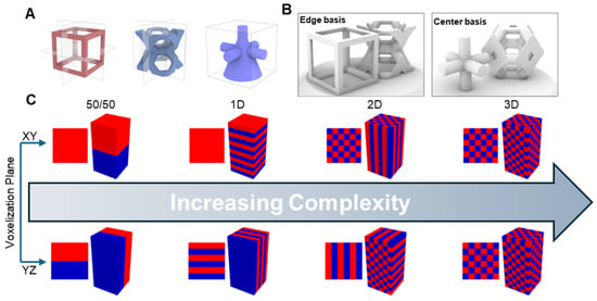
Homogeneous lattice structures are typically created by generating a regular grid of voxels throughout the design domain, populating each voxel with the same unit cell design, including topology and element thickness [32]. Input dimensions include the voxel edge length or cell length (lc) and element radius (r), which can also be described in nondimensional form (r* = r/lc). To create a patterned lattice, multiple unit cells are designed and patterned throughout the primitive shape. For this study, cubic and Kelvin unit cells were chosen with identical input dimensions. This study tested patterned lattices designed with XY and YZ voxelization planes. The voxelization plane is the reference plane for discretization of the primitive geometry. This can be aligned with the primary Cartesian axes or oriented with an arbitrary normal vector [35]. For homogeneous lattices, the voxelization plane does not have a significant effect on the lattice design. However, in patterned lattices, changes to the voxelization plane can yield different lattices. Functional grading is a typical strategy in which a characteristic quantity is varied throughout the design domain, either globally or at the voxel level [38]. Designing a lattice to have smaller strut thickness at its center is a common example of functional grading in 3D-printed lattices as it can reduce clogging [36]. Certain unit cell geometries can be defined in multiple bases; simple cubic can be described as a cube (edge-based) or a cross-like structure (center-based) as seen in Figure 1. Regardless of basis, reflection symmetry is maintained about the primary Cartesian axes. A similar description can be made for the Kelvin unit cell, in which the pore is centered within the voxel or split between the faces (edge-based), sometimes referred to as the vintiles unit cell [39]. In a homogeneous lattice, a unit cell can be defined by a voxel centered at any point that does not intersect with the primitive wall. Center- and edge-based unit cells are two possible locations to center the voxels. The repeating structure is the same but is defined by a different center point.
Figure 1.
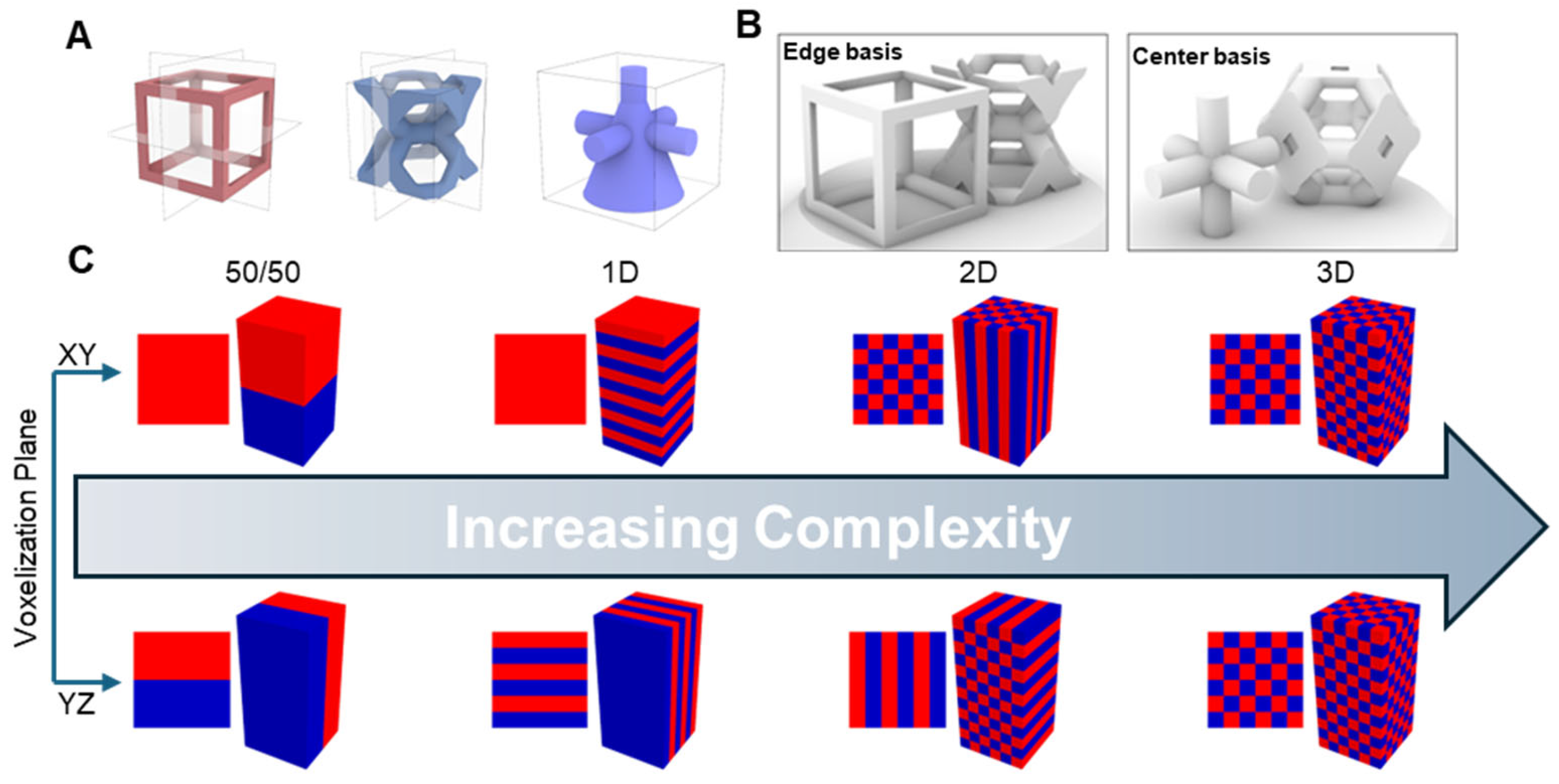
(A) Visualizations of cubic, Kelvin, and directional unit cells; (B) visualizations of cubic and Kelvin unit cells defined by edge and center basis; (C) examples of possible patterns for patterned lattices with two distinct unit cells where red and blue indicate different unit cell placements, indicating top–down projection (left) and perspective (right) views for each configuration. These patterns are organized in order of increasing complexity in 3D space.
In a homogeneous lattice, the choice of unit cell basis is largely inconsequential. However, in patterned lattices, neighboring unit cells must have compatible edge- or center-based geometry. With this satisfied, it is possible to create patterned combination lattice structures in 1D, 2D, and 3D. For a given voxel within the lattice, populated with unit cell A, this voxel could have a von Neumann neighborhood populated with unit cell B containing a different unit cell geometry. This type of patterned structure is only possible where the basis of both unit cell geometries consists of elements in analogous positions, or else the lattice would not be self-supporting. This is illustrated in Figure 1. The concept of unit cell basis can be further combined with modifications to unit cell symmetry, enabling uniform lattice structures with inherent directionality or anisotropy. This can be achieved by removing the constraint of reflection symmetry about the XY plane, permitting pyramid-like structures with rotational symmetry about the vertical axis (Figure 1A). The design of a pyramid unit cell with an arbitrary base shape is enabled by selecting a unit cell basis that positions the features of a cubic unit cell at the center of the bounding box, rather than the edges (Figure 1B). For lattice design and parameter selection, the geometric properties of pyramids enable a unique set of comparisons. The volume of a pyramid is defined as B∙h/3, where B is the area of the pyramid base and h is the pyramid height. By imposing equal base area and height between pyramids, the solid volume will be equal, regardless of the number of sides (including a circular base or cone). By extension, the porosity will also be comparable between unit cells with different pyramid designs. Scaling the unit cell is facilitated by defining nondimensionalized quantities analogous to the dimensionless radius (r*)—namely base area (B* = B/lc2) and height (h* = h/lc). The design process also affords a rotational degree of freedom about the center axis of the pyramid.
In summary, lattice performance can be modulated through three independent but interacting design choices: unit cell basis, voxelization plane, and local symmetry breaking within the unit cell.
2.3. Design
Parts were designed in Rhino 6 and Grasshopper on a Windows 10 desktop with an Intel(R) Core (TM) i5-4460S CPU @ 2.9 GHz, 16 GB RAM, and 2 GB dedicated graphics. In-house scripts were used with the Crystallon and Dendro plugins for generating lattice structures. Voxelization components from Crystallon were adapted to produce the framework for patterning alternating unit cells. In-house features are available at https://github.com/fromenlab/LatticeTools, accessed on 15 April 2026. All configurations used the technique for generating uniform conformal lattices described previously [32]. Lattice dimensions were selected to align with previous studies for comparison, using cell lengths (lc) of 2.38 mm or 4.48 mm and dimensionless radius (r* = r/lc) of 0.11. Smaller cell lengths were used in a pipe system of internal diameter 12.2 mm, and larger cell lengths used for internal diameter 34.1 mm. Large voxel samples were designed to have a height of 20 voxels while small voxel samples had a height of 40 voxels. This meant all samples were approximately 100 mm in height. Lattices based on alternate cell designs and alternating voxels were designed for the smaller system, with a subset made for the large system. Lattices used for parameter testing in directional lattices were designed for the larger system only to ensure that pyramidal features would be resolvable by the fabrication process. Directional lattices used parameters of r* = 0.11, B* = 0.5, h* = 1, unless otherwise indicated.
2.4. Additive Manufacturing
All parts were fabricated using UMA 90 Black resin and a Carbon M1 3D printer (Carbon, Redwood City, CA, USA) with 75 µm resolution in the XY plane. The M1 uses a vat photopolymerization technique, Continuous Liquid Interphase Production (CLIP), in which entire XY cross sections of a part are cured as a platform moves up and out of the resin pool. Pre-processing was performed using the Carbon software, and post-processing (solvent washing and curing) was performed according to manufacturer recommendations. Notably, this lattice generation technique enables entirely support-free printing, which reduces material waste and both pre- and post-processing resource demand. Parts were printed at the standard 100 µm resolution in the Z direction, except for the noted directional samples printed with 25 µm Z resolution.
2.5. Characterization
All parts were first characterized in mesh format by the native utilities for volume and surface area in Rhino 6/Grasshopper. After printing and post-processing, the mass of each part was recorded and converted to estimated volume using the specified solid density (1.2 g/mL). For the diamond-based directional lattices, X-ray computed tomography was performed on a Buker Skyscan 1276 with the following settings: 40 kV, 200 µA, 6.5 µm pixel size, 400 ms exposure, with no filter over 180° at a rotation step of 0.2°. Due to the computational demands of this resolution setting, volume and surface area were not quantified. Instead, the scan morphology was qualitatively compared to the CAD design. CT reconstruction was performed using NRecon 1.7.4.6, 3D Slicer 5.0.3, and the SlicerMorph ImageStacks plugin.
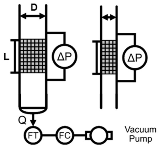
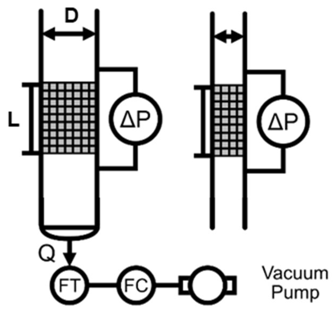
Pressure gradient was measured in one of two configurations (Figure 2), depending on sample size and set. For samples based on alternate unit cell basis and alternating voxel patterns, pressure gradient was evaluated with an Ashcroft CXLdp differential pressure transmitter (Ashcroft, Inc., model CX8MB2421IW, Stratford, CT, USA) in the respective pipe size for the sample (ID = 12.2 mm; ID = 34.1 mm). Pressure was measured from taps placed on either side of the sample zone [36]. For directional lattice samples used to evaluate pyramid design and processing parameters, the pressure gradient was evaluated with a Dwyer differential pressure gauge (Dwyer Instruments, Inc., 0–248.84 Pa ± 2%, Michigan City, IN, USA). Pressure was measured from taps positioned 50 mm apart, and the sample center was positioned at the center of the measurement zone, such that an equal length of the part extended on either side. This measurement approach was taken to minimize the influence of entrance or exit flow effects. Flow control was performed using a mass flow meter, flow controller, and vacuum pump (TSI 4043, TSI, Inc., Shoreview, Minnesota, USA; DFM 2000, TPK 2000, and HCP5, Copley Scientific, Ltd., Nottingham, UK).
Figure 2.
Experimental setup examples. Pipe inner diameters include 12.2 mm and 34.1 mm. Relative dimensions not to scale. Q = volumetric flow rate; ΔP = pressure difference; FT = mass flow meter transmitter; FC = flow controller; D = diameter; L = length which is ~100mm. A vacuum pump was used alongside the associated FC to allow for precise and constant flow.
Pressure gradient was modeled using R v4.2.3. Where applicable, pressure behavior was first modeled in terms of general viscous and inertial terms, according to Equation (1). Then, assuming minimal deviation from the CAD-derived geometric properties, the tortuosity was fit based on Equation (2), using the nls package. As appropriate, the influence of other parameters, including unit cell basis, voxel plane orientation, part orientation, print orientation, and slicing, were evaluated by ANOVA using Type III sum of squares. Code associated with analysis can be found at https://github.com/fromenlab/manuscript-2026-anisotropic-lattice, accessed on 15 April 2026.
3. Results and Discussion
3.1. Patterned Lattice Combinations
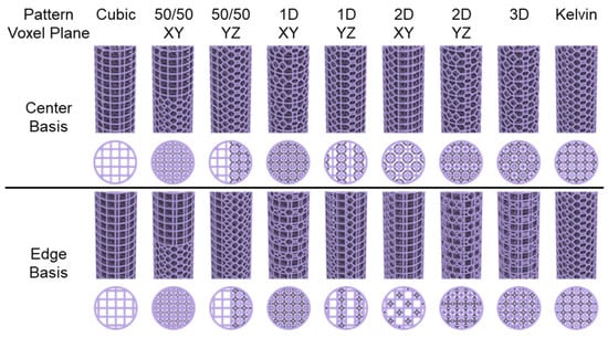
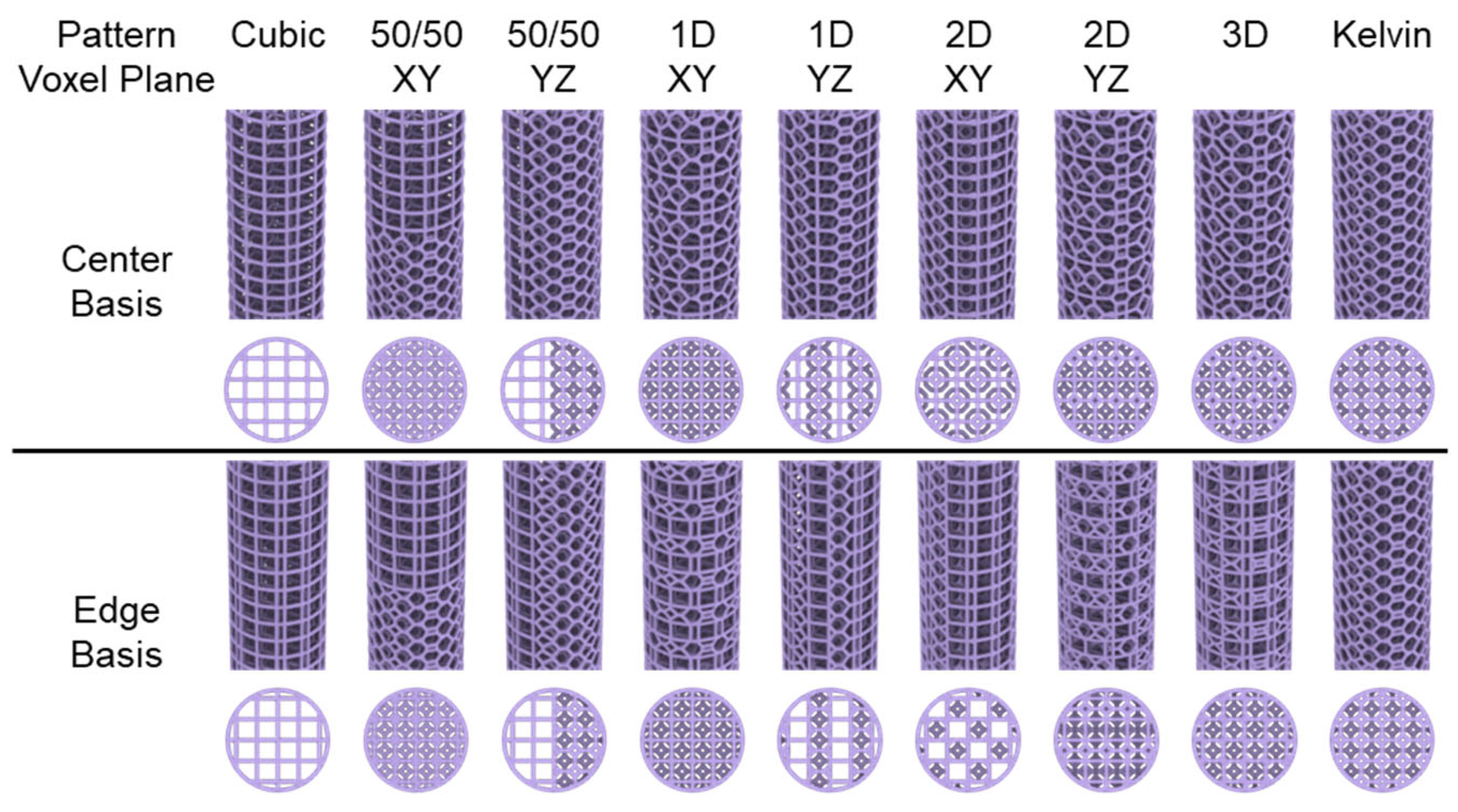
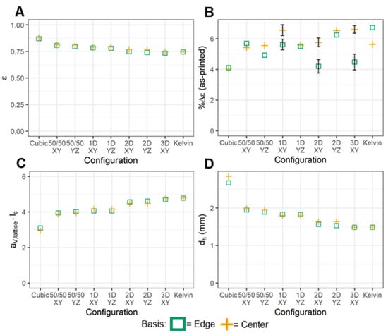
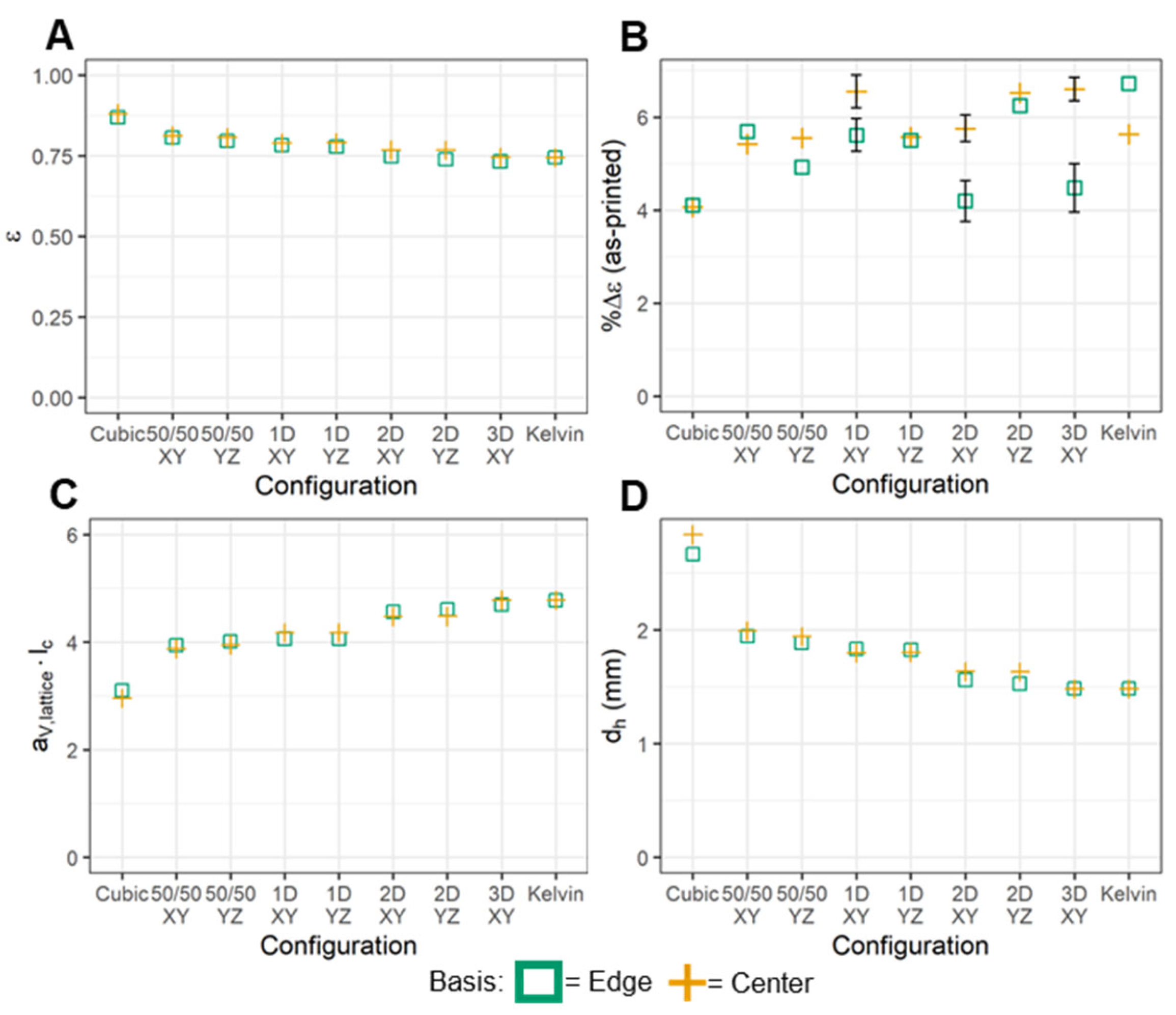
Pattern lattices were designed with cubic and Kelvin unit cells in increasingly complex patterns. Patterns affected by voxelization plane were designed with an XY plane and then redesigned with a YZ plane. Top and perspective views of tested patterned lattice conditions can be seen in Figure 3. Geometric quantities were computed for a single unit cell of the center-based cubic and Kelvin lattices, shown in Figure 4. At the level of a single cell, center-based and edge-based geometries for the same unit cell type share effectively identical values at a common r*. Since the single-cell properties align with previous reporting, the column-scale behavior was expected to also result similarly. Lattice design parameters for column-shaped parts were selected to align with previous dimensions and techniques, including dimensionless radius (r* = r/lc = 0.11) and cell length (lc = 2.38 mm) [36]. At the overall part scale (Figure 4), trends for cubic and Kelvin columns are consistent with previous reports and show minor differences between the unit cell bases. Cubic geometries yield the highest porosity and hydraulic diameter and Kelvin geometries the lowest, with each dimension of combination yielding an intermediate value. Considering a change in voxel plane from XY to YZ, CAD-based geometric properties vary negligibly and less than the step between combination dimension (e.g., from 1D to 2D). Although porosity was comparable between all configurations, ranging between roughly 75–85%, the properties of combination structures are heavily influenced by the inclusion of Kelvin features. This effect is most apparent in the estimated hydraulic diameter.
Figure 3.
Rendering of tested homogeneous and patterned lattice designs (perspective and top views). Conditions listed in order of increasing complexity and grouped by unit cell basis and voxel plane symmetry.
Figure 4.
Part-scale properties for tested homogeneous and patterned lattices; (A) porosity, (B) porosity change, (C) specific surface area times unit cell length, and (D) hydraulic diameter of edge- and center-basis patterned lattices. Porosity, specific surface area per unit length, and hydraulic diameter are calculated with CAD properties, thus yielding single values per part. Porosity change was calculated with measured porosity of the printed lattices. Error bars reported for parts printed in triplicate. Conditions without error bars were not printed in replicate due to the minimal variability from as-printed parts.
To compare the design values to the as-printed dimensions, each column was weighed, and the porosity was estimated using the specified material properties. All parts exhibited reduced mass compared to the expected value and an increase in porosity between 4 and 7% (Figure 4B). Even with the change in porosity, the trends shown in Figure 4A,C,D were maintained in the as-printed parts, which suggests that the CAD estimates can be used effectively to compare design candidates on a relative basis. A set of replicates was printed for the 1D XY, 2D XY, and 3D combinations. Across all configurations, there was a statistically significant difference between the porosity increases in edge-based and center-based unit cells (Table S3), with center-based combinations consistently exhibiting greater porosity change.
3.2. Fluidic Performance
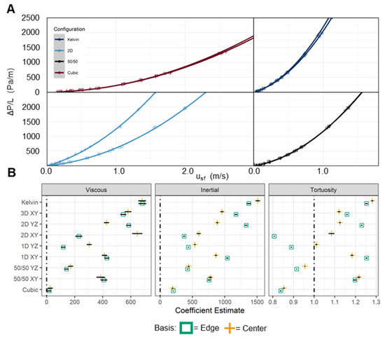
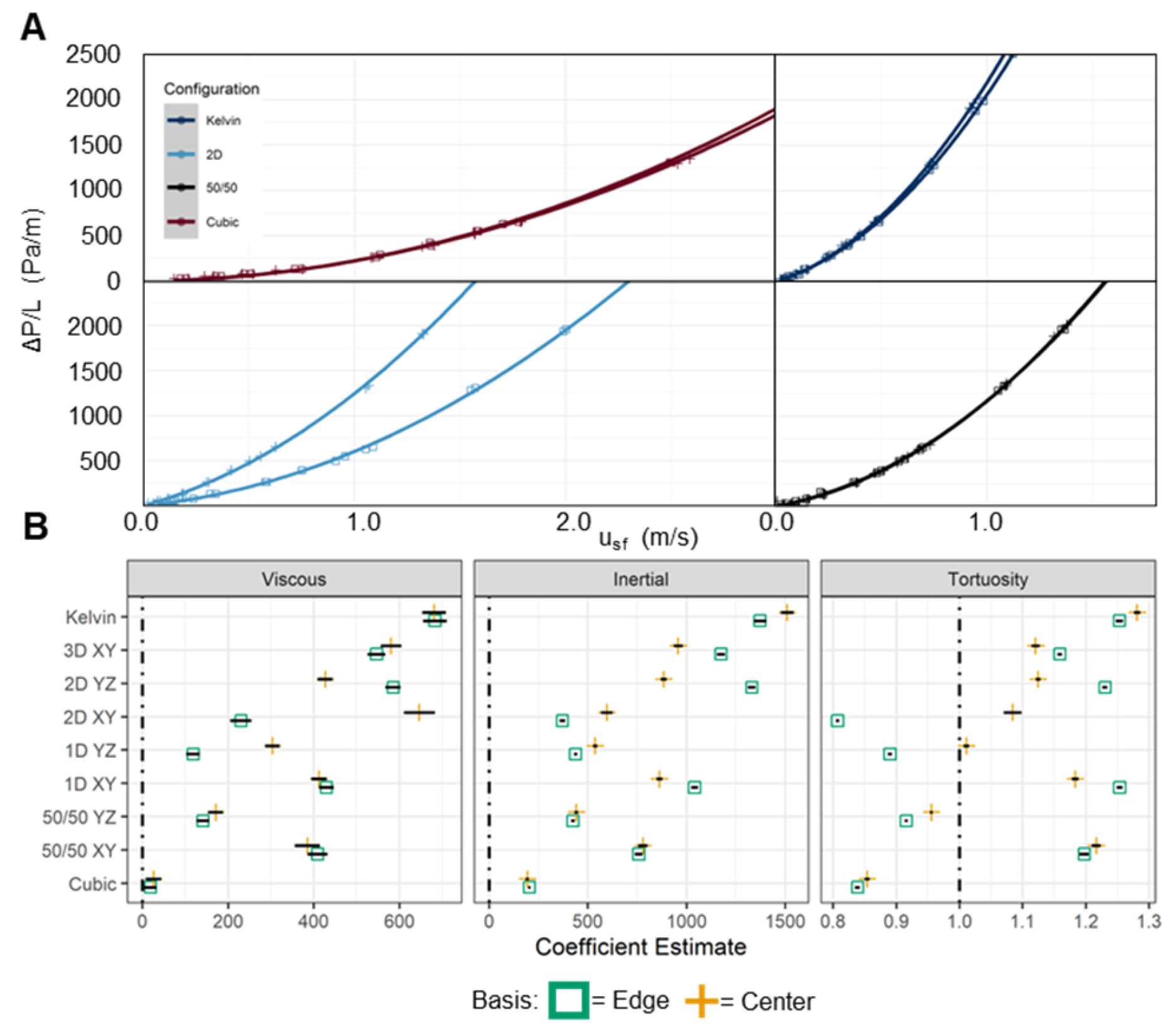
To evaluate the configuration-based differences in fluid performance, the pressure drop across each column was measured over a range of flow conditions. The results of pressure drop measurements for cubic, Kelvin, 2D, and stacked 50/50 are reported in Figure 5 and the results for all combinations of cell basis and voxel plane can be found in Figure S3. Observations for cubic, Kelvin, and 50/50 XY were consistent with the previously reported results [36]. Considering only XY-based voxelization, edge-based structures increased in pressure gradient in order of 2D, 50/50, 1D, then 3D, suggesting that a higher-order combination does not necessarily result in an increased pressure gradient. These trends were also supported by observations in a larger experimental system, which consisted of a larger pipe diameter and larger unit cell dimensions (Figure S4). Center-based cells corrected this trend to some degree, increasing the pressure gradient of the 2D combination to a level comparable to the stacked column pressure gradient. However, the pressure gradient for the center-based 1D combination still exceeded the 2D and stacked combinations.
Figure 5.
(A) Pressure drop measurements for Kelvin, 2D XY, 50/50, and cubic lattices. Fit for Equation (1) is plotted for each series. (B) Fit values from Equation (2) for viscous and inertial coefficients as well as tortuosity estimates.
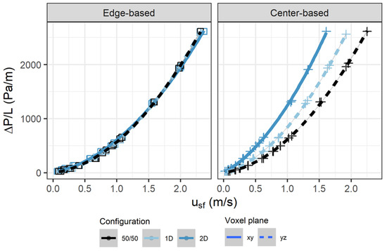
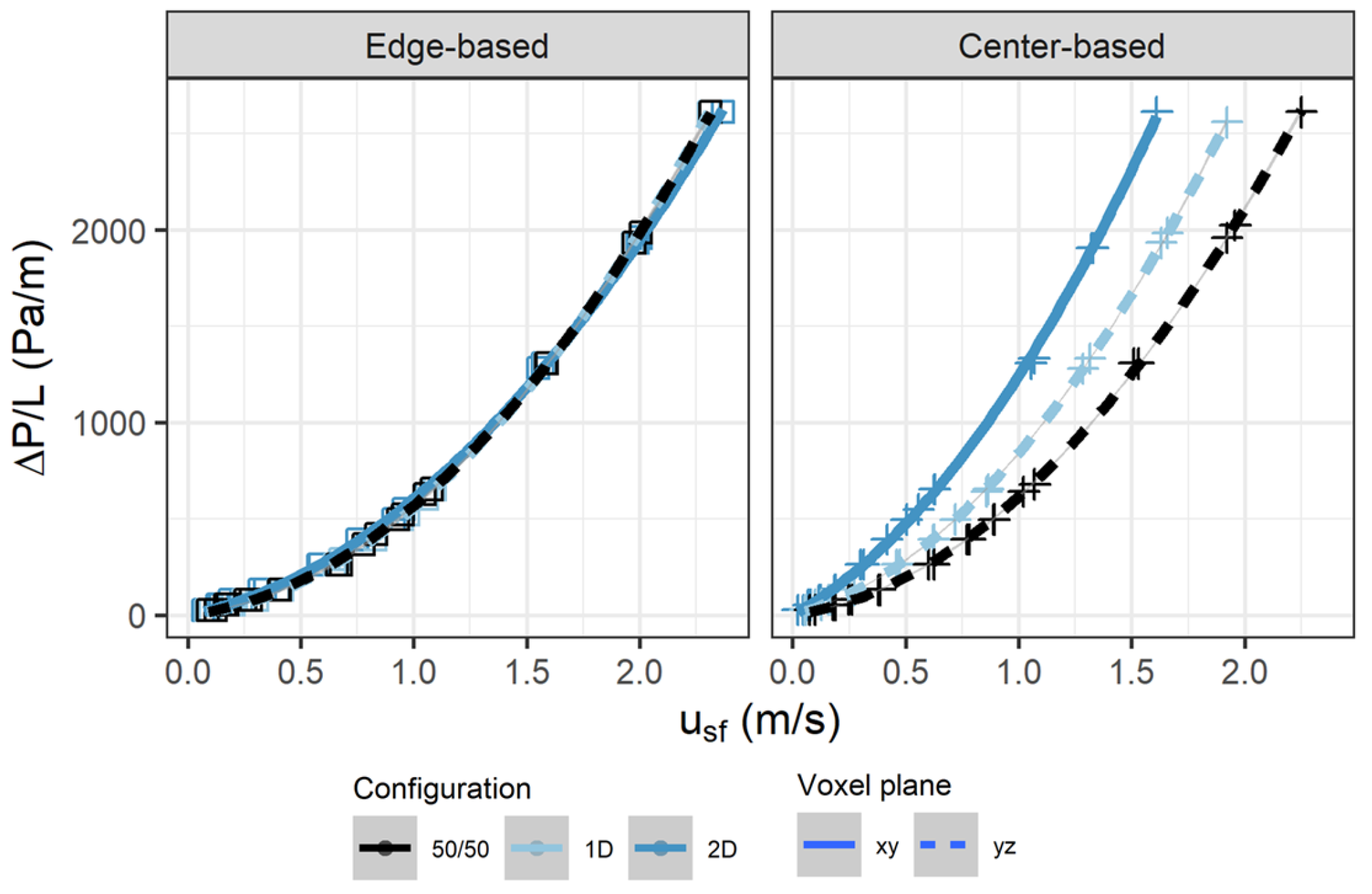
The influence of voxel plane orientation was examined for only stacked, 1D, and 2D columns (Figure 6) because the symmetry of other configurations produced effectively identical structures. Shifting from an XY to YZ voxel plane led to a decrease in pressure gradient for 50/50 and 1D combinations. However, the voxel plane shift increased the pressure gradient observed in 2D combinations. The increase was more pronounced for the edge-based combination, for which the pressure gradient became greater than the center-based combination in the YZ plane. In the 50/50 and 1D cases, the voxel plane shift from XY to YZ also resulted in a lower pressure gradient for edge-based combinations compared to the equivalent center-based combination.
Figure 6.
Pressure drop measurements for edge- and center-based lattices which contain 50% Kelvin and 50% cubic unit cells in each cross-sectional slice. Fit for Equation (1) is plotted for each series.
Comparing the pressure gradient between edge-based and center-based lattices, all configurations showed statistically significant differences between the unit cell designs (p < 0.001), except for the 50/50 XY column. However, not all of these differences were physically apparent. Cubic and Kelvin columns showed negligible performance differences at the observed flow rates. 3D, 1D XY, and 50/50 YZ performance differences were less apparent than 1D YZ and both 2D combinations. Further statistical inferences were made by fitting viscous and inertial coefficients from Equation (1). Coefficients are shown in Figure 5, where the described performance differences across changes in unit cell basis, combination, and voxel plane are reflected in the relative changes in model coefficients. Only the cubic configuration yielded a negligible viscous term, which is consistent with previous findings of having primarily turbulent, inertia-dominant flow behavior [35,36]. Otherwise, the relative pressure gradient for all configurations can be approximately inferred from the magnitude of the inertial coefficient of the given configurations.
Taking the CAD-derived geometric properties and observed pressure gradient, the model form of Equation (2) was also used to estimate the tortuosity of each structure (Figure 5). In this case, the estimated value is representative of the average hydraulic tortuosity over the flow range. Estimated tortuosity trends follow those of the inertial coefficient, but the tortuosity term can yield some additional insight into the intrinsic geometric characteristics of each structure. Hydraulic tortuosity is defined as the average path of a fluid through a unit cell divided by the shortest path through the unit cell. This definition requires a lower bound of 1 and has the cubit unit cell approach this limit [36]. However, the fitted parameter is the hydraulic tortuosity averaged over the flow range (radial and Z height average). By averaging over the flow range, the flow between unit cells becomes coupled. This removes the lower bound of 1 as flow could enter unit cells at planes other than the upstream XY plane. Beam thinning and porosity increases from the print process could also lower the tortuosity estimates as the CAD-derived geometric properties are used in Equation (2).
From the fit tortuosity values (Figure 5B), it can be inferred that results closer to the limit of the cubic column arise from configurations which yield straighter overall flow patterns. In the cases of 50/50 YZ (edge- and center-based), 1D YZ (edge-based), and 2D YZ (edge-based) combinations, all have near-cubic tortuosity estimates but greater observed pressure gradients than a simple cubic column. The combination of low tortuosity and a relatively higher pressure gradient suggests that a greater fraction of the flow may be channeled through the open cubic pores in these configurations, as suggested for the larger pores in Kelvin lattices [37]. As a result, the effective interstitial velocity through those regions would be increased, yielding a higher pressure gradient.
The implications of unit cell basis and voxel plane are highlighted for configurations in which the fraction of unit cell types perpendicular to the flow direction are equal (i.e., 50% A cells and 50% B cells distributed in a cross-sectional slice). Three cases are shown in Figure 6 for both edge-based and center-based cells, using 50/50 (YZ), 1D (YZ), and 2D (XY) alternating patterns. For all edge-based configurations, the pressure gradient is effectively the same. However, changing to a center-based cell design yields a pressure gradient positively correlated with pattern complexity. At first consideration, this trend may have resulted from porosity and surface area changes that occur as fewer lattice elements overlap and more elements are exposed. However, the tortuosity estimate controls for these changes in geometric properties, and these estimated values roughly coincide with the observed differences in pressure gradient. Thus, the symmetry parameters associated with unit cell basis and voxel plane can be selected to modulate the effective tortuosity and fluid phenomena in these systems.
3.3. Homogeneous Directional Lattices
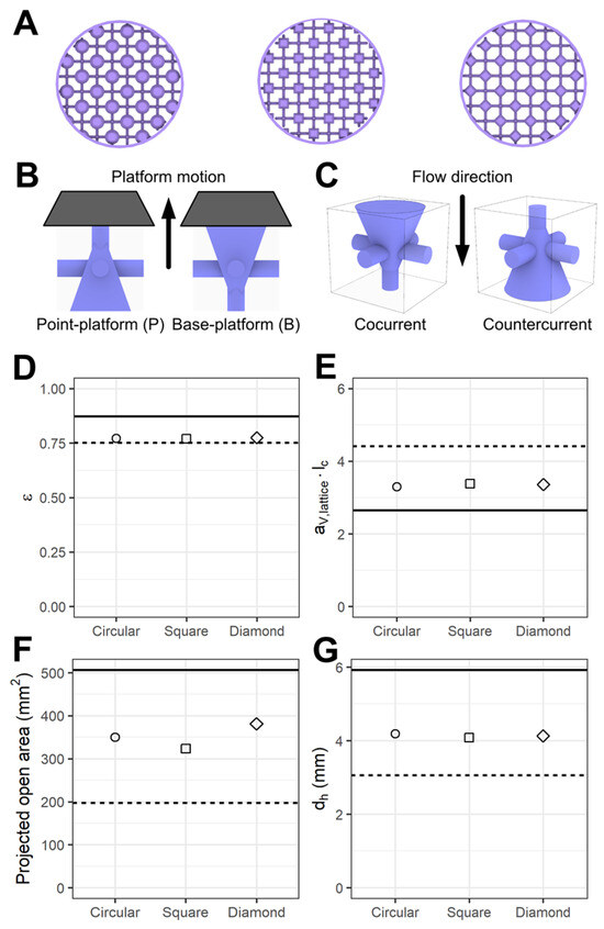
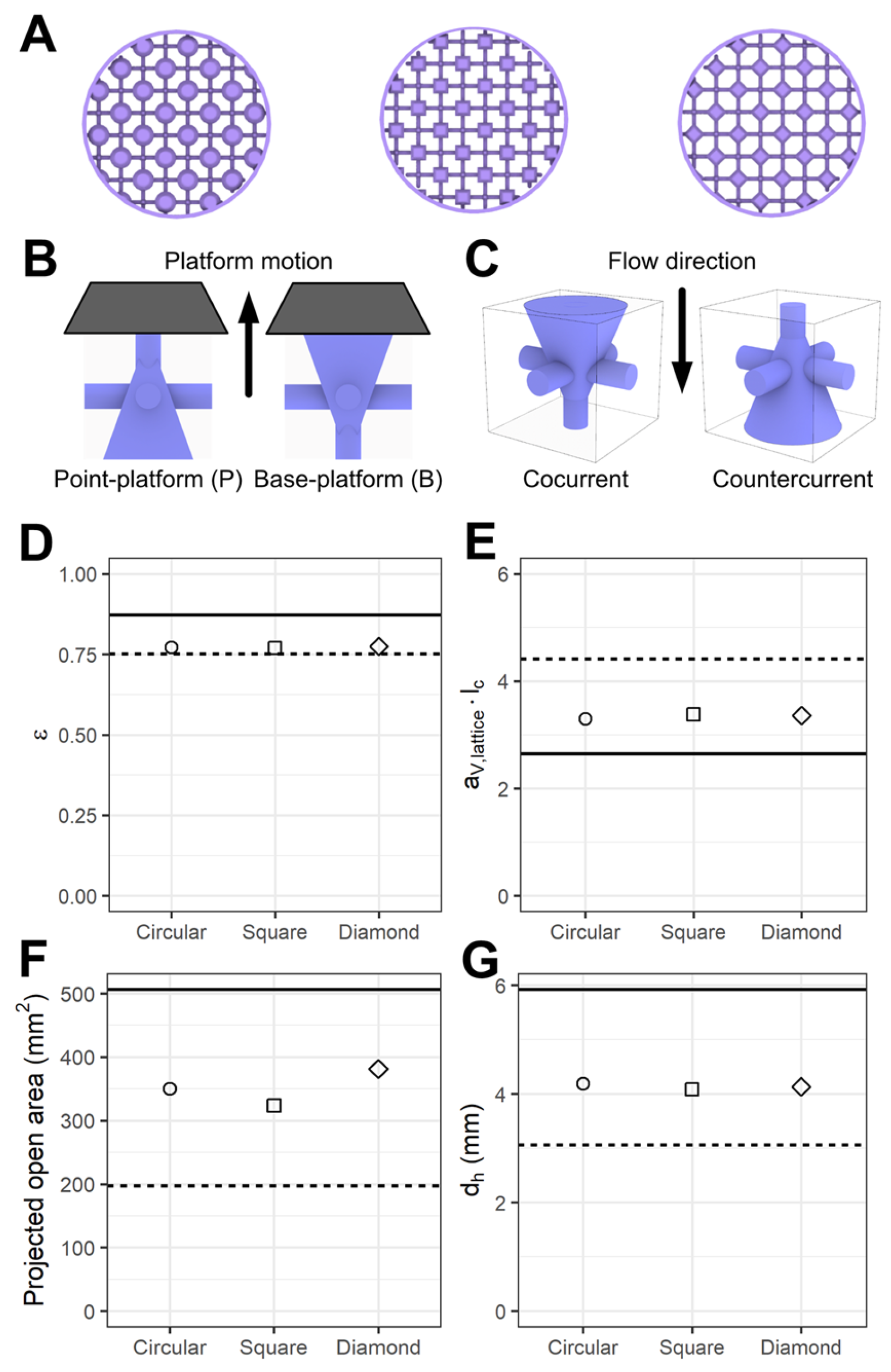
Three pyramid designs were selected for comparison at equal porosity, using a base of a circle, square, or diamond (rotated square) to achieve 90° rotational symmetry about the center vertical axis. For computational expedience and ensuring feature resolution, directional lattice designs were generated at a larger scale consistent with previous dimensions [36]. Lattices were designed with lc = 4.48 mm, r* = 0.11, B* = 0.5, and h* = 1. Each lattice was printed and tested in two orientations, for a combination of four conditions per design. Figure 7 shows CAD-based geometric properties and the treatment scheme for parameter investigation. The pyramid lattices have intermediate geometric properties compared to their cubic and Kelvin equivalents. The design porosity, dimensionless specific surface area, and hydraulic diameter were approximately equal for all pyramid configurations, consistent with the design ideal. However, the pyramid configuration did affect the projected open area in the flow direction, resulting from differences between pyramid and beam overlap. The square pyramid initially had the lowest projected open area but rotating it into the diamond configuration led to an increase, surpassing the circular pyramid lattice.
Figure 7.
(A) From left to right: top views of directional lattices with circle, square, and diamond pyramid bases. (B) Schematic of point–platform and base–platform orientation to the print bed. (C) Schematic of cocurrent and countercurrent directional lattices with flow direction. (D) Porosity, (E) specific surface area times unit cell length, (F) projected open area, (G) and hydraulic diameter of designed directional lattices. Values for homogeneous cubic and homogeneous Kelvin lattices are indicated with solid and dashed lines, respectively.
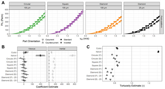
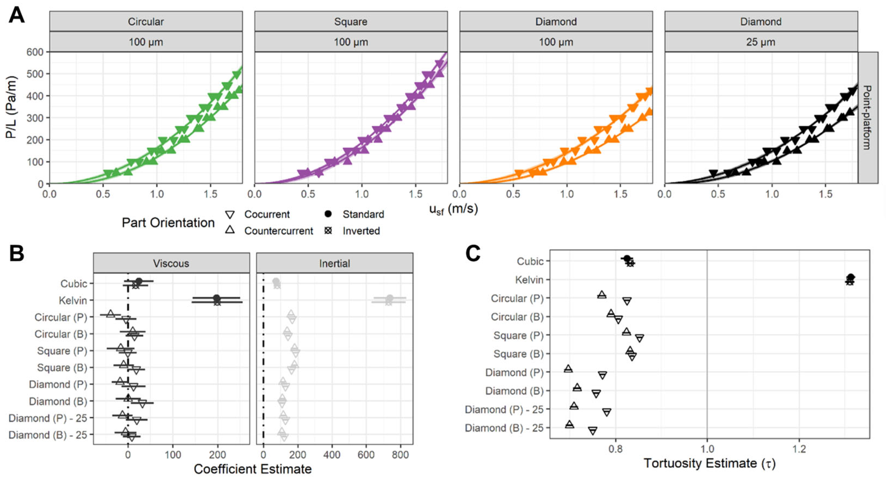
To evaluate the orientation dependence of pressure-driven flow over these lattice structures, lattice parts were first printed with the point of the pyramid facing the print platform (point–platform, Figure 7B). Lattices were also printed with the base of the pyramid facing the print platform (base–platform). These yielded lower quality prints. Analysis of the printability and fluidic performance of the base–platform lattices can be read in the Supplemental Information. Since point–platform lattices printed better, testing began with these lattices. Each part was placed in a cocurrent or countercurrent orientation with respect to the air flow in the system. In the cocurrent orientation, the point of the pyramid was directed to the system outlet; in countercurrent, the point was directed to the inlet (Figure 7C). Results of the pressure experiments are shown in Figure 8A. Consistent with the geometric properties, pressure gradients were greater than cubic lattices and less than those observed for Kelvin lattices. Diamond pyramid structures exhibited the lowest pressure gradient, followed by circular and square pyramids, indicating an inverse trend with projected open area. Orientation-dependent pressure gradients were observed for all parts and were statistically significant based on ANOVA model comparison (flow-relative orientation: circular and diamond, p < 0.001; square, p ~ 0.06). Notably, the increase in projected open area of the diamond lattice also corresponded to a wider difference between the orientations, visible at higher flow rates.
Figure 8.
(A) Pressure drop measurements for circular, square, and diamond directional lattices as printed by point–platform and base–platform orientations. Fit of Equation (1) is plotted for each series. (B) Viscous and inertial coefficients for directional lattices estimated from Equation (2). (C) Estimates of tortuosity for directional lattices.
3.4. Patterned Directional Lattices
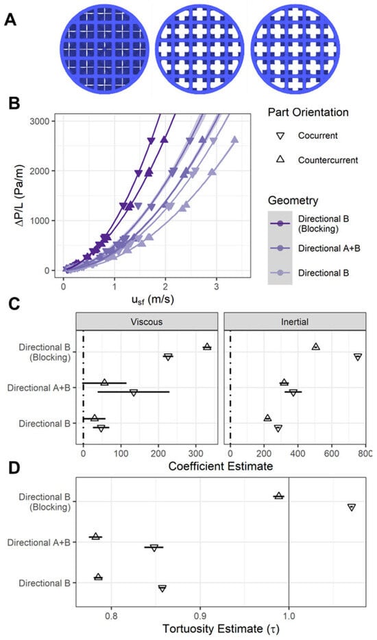
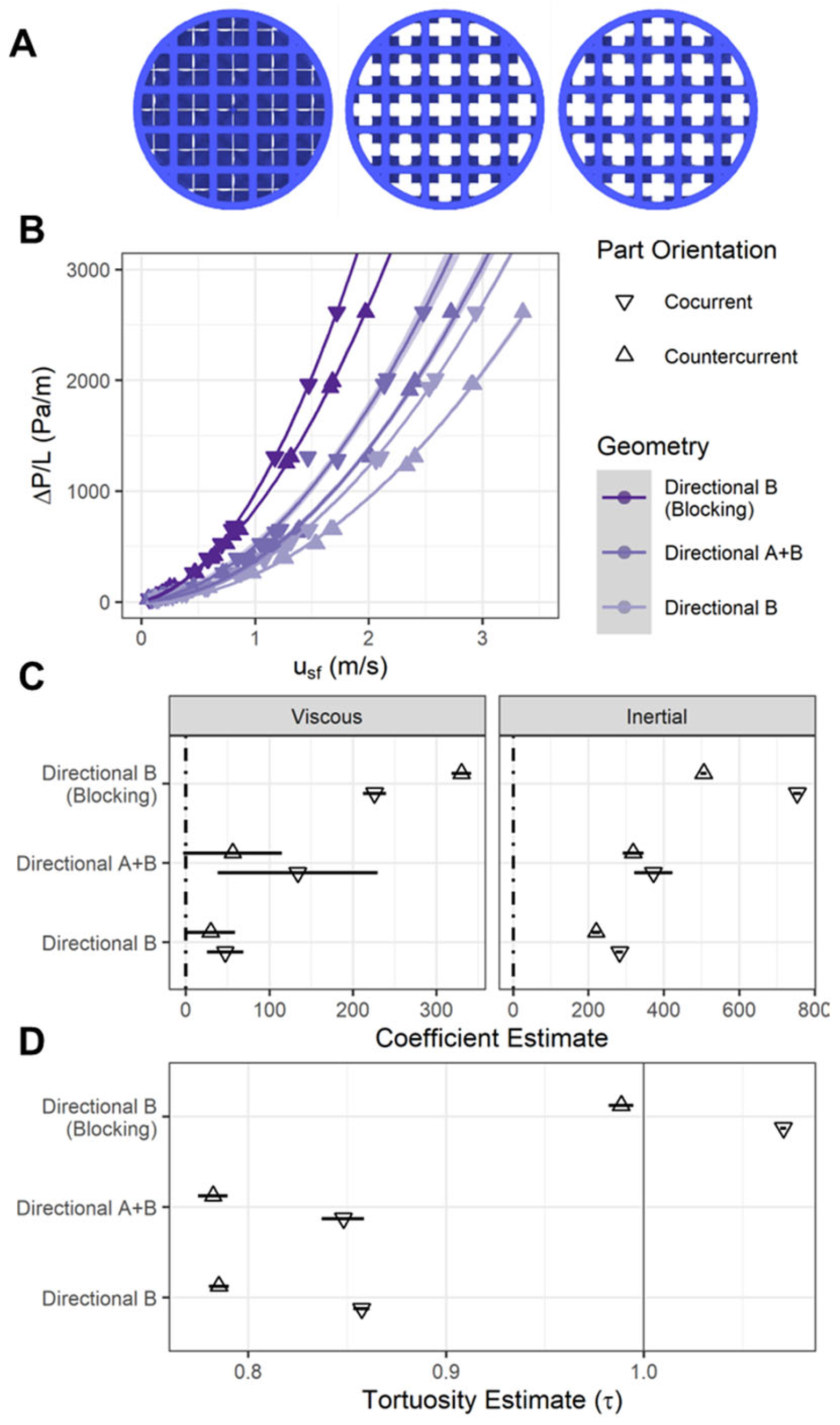
Leveraging both design paradigms of unit cell patterning and directionality demonstrated here, a set of 3D patterned pyramid lattices was designed to further investigate the tunability of directional lattice performance. At the same scale of the patterned unit cells (lc = 2.38 mm, r* = 0.11), one sample had all voxels (A + B) containing square pyramid unit cells, as in the previous directional designs; one sample with only half of voxels (B) containing a square pyramid unit cell; and a third with half of the voxels (B) containing a square pyramid unit cell with the base extending to the bounds of the unit cell (B* = 1). The design in the third condition was intended to block all straight paths through the column.
The pressure gradient and modeled coefficients for the combination-directional lattices are shown in Figure 9. Pressure gradient, coefficients, and tortuosity estimates are highest for the blocking lattice structure, followed by the fully populated directional column, then the partially populated directional column. Only the blocking configuration exhibited statistically significant viscous coefficients in both cocurrent and countercurrent orientations, supported by its increased pressure gradient compared to the other configurations. Both the fully populated (A + B) and partially populated (B) directional columns returned tortuosity estimates below 1 and are comparable to the pure cubic column. All columns yielded increased tortuosity estimates for cocurrent orientation compared to countercurrent orientation. Statistically significant orientation effects confirm that the directionality of these structures is maintained at smaller length scales, which may be relevant for miniaturized devices. Thus, in addition to pyramid base shape and projected open area, partial population is a viable parameter for tuning the performance of these directional structures.
Figure 9.
(A) From left to right: top views of directional B (blocking, B* = 1), directional B (non-blocking, B* = 0.5), and directional A + B (non-blocking, B* = 0.5). Since the lattices are made in the 3D pattern, directional A + B and directional B only (non-blocking) have the same XY projection; (B) pressure drop measurements for cocurrent and countercurrent flow with a fit from Equation (1) plotted for each series; (C) viscous and inertial coefficient fits from Equation (2); (D) tortuosity estimates from Equation (2).
4. Conclusions
This work has introduced and demonstrated two design paradigms based on symmetry modulation at scales spanning the unit cell, local regions, and overall part. Careful selection of unit cell basis can enable multiple types of unit cell patterning, and combined with changes in voxel plane basis, the tortuosity of lattice structures can be tuned beyond the extent of a uniform lattice column. Furthermore, selecting an anisotropic unit cell design can result in directional fluid performance. Future work will benefit from improved characterization of as-printed part porosity and surface area to enable more accurate quantification of tortuosity. Nevertheless, the combination of these approaches has important implications for controlling local and part-scale transport phenomena in these lattice structures, leading to two types of directional behavior—cocurrent or countercurrent. These results are shown to be valid across unit cell length scales and overall part scales alike, as well as robust to print defects. Importantly, these effects arise from symmetry selection rather than material choice or post-processing. Such design flexibility could benefit two-stage processes in which lattice cartridges or monoliths are used as a substrate, wherein the lattice is exposed to flow in one direction during a given step, followed by flow in another direction for another step. Alternatively, these designs could be integrated into previously suggested cellular fluidics for novel catalytic, separations, or diagnostic processes. In total, these developments highlight several advantages lattice structures have over traditional stochastic foams, making them a robust platform for next-generation composite materials in a multitude of applications.
5. Patents
I.R.W., D.J.H, and C.A.F. acknowledge the submission of a patent application related to the work (application no. 63/938,567; filing date 11 December 2025).
Supplementary Materials
The following supporting information can be downloaded at https://www.mdpi.com/article/10.3390/jcs10050246/s1. Figure S1: Porosity (A), specific surface area times unit cell length (B), and hydraulic diameter divided by unit cell length (C) of edge and center basis lattices closely match the CAD designed values for both Cubic and Kelvin unit cells; Figure S2: CAD design of pyramid unit cell (A) compared to computed tomography scans of point-platform (B) and base-platform (C) lattices printed at 100 μm slicing. Computed tomography scans of point-platform (D) and base-platform (E) lattices printed at 25 μm slicing. Some unit cells printed in a base-platform orientation exhibit the “missing linker”-like defect (F). All base-platform prints exhibited rounded pyramid bases. Porosity change from design to printed part (G) reveals base-platform consistently having higher porosity changes; Figure S3: Pressure drop measurements from edge-based and center-center lattices (A). Edge-based and center-based pressure drop measurements for the same configuration are also shown (B–G); Figure S4: Pressure drop measurements for the large diameter lattices tested (A–D). The plotted fit is Equation (1). Viscous, inertial, and tortuosity coefficients estimates from the fit (E). Table S1: P values between patterned lattices as measured through a two-way ANOVA; Table S2: Viscous coefficients, inertial coefficients, and tortuosity fit values for all tested configurations. Data shown: average (standard deviation); Table S3: Welch two sample t test results comparing % porosity changes of edge vs center based lattices.
Author Contributions
Conceptualization, C.A.F. and I.R.W.; methodology, I.R.W.; software, I.R.W. and D.J.H.; validation, I.R.W.; formal analysis, I.R.W.; investigation, I.R.W.; resources, C.A.F.; data curation, I.R.W.; writing—original draft preparation, I.R.W. and C.A.F.; writing—review and editing, I.R.W., D.J.H. and C.A.F.; visualization, D.J.H. and I.R.W.; supervision, C.A.F.; project administration, C.A.F.; funding acquisition, C.A.F. All authors have read and agreed to the published version of the manuscript.
Funding
This work was supported by the National Science Foundation under award number 2237430. I.R.W. was supported by a GAANN Fellowship funded by the Department of Education (P200A210065). Micro-CT imaging was supported by the National Institutes of Health, National Institute of General Medical Sciences COBRE (P20 GM139760). The content is solely the responsibility of the authors and does not necessarily represent the official views of the National Institutes of Health, National Science Foundation, or Department of Education.
Data Availability Statement
Code is made available as reported in the methods and additional data provided in the Supplementary Material. Any additional information required to reanalyze the data reported in this paper is available from the corresponding author upon request.
Conflicts of Interest
I.R.W., D.J.H., and C.A.F. acknowledge the submission of a patent application related to the work (application no. 63/938,567; filing date 11 December 2025). The authors declare no additional conflicts of interest.
Abbreviations
The following abbreviations are used in this manuscript:
| POCS | Periodic open cellular structures |
| CLIP | Continuous Liquid Interphase Production |
| FT | Mass flow meter transmitter |
| FC | Flow controller |
| D | Diameter |
| L | Length |
References
- Kronenfeld, J.; Lukas, R.; Max, A.S.; Dulay, M.; Joseph, D. Roll-to-roll, high-resolution 3D printing of shape-specific particles. Nature 2024, 627, 306–312. [Google Scholar] [CrossRef] [Scilit] [PubMed]
- Tumbleston, J.R.; Shirvanyants, D.; Ermoshkin, N.; Janusziewicz, R.; Johnson, A.R.; Kelly, D.; Chen, K.; Pinschmidt, R.; Rolland, J.P.; Ermoshkin, A.; et al. Continuous liquid interface production of 3D objects. Science 2015, 347, 1349–1352. [Google Scholar] [CrossRef] [Scilit]
- Moussa, A.; Melancon, D.; El Elmi, A.; Pasini, D. Topology optimization of imperfect lattice materials built with process-induced defects via Powder Bed Fusion. Addit. Manuf. 2020, 37, 101608. [Google Scholar] [CrossRef] [Scilit]
- Dong, G.; Tang, Y.; Zhao, Y.F. A 149 Line Homogenization Code for Three-Dimensional Cellular Materials Written in matlab. J. Eng. Mater. Technol. 2019, 141, 011005. [Google Scholar] [CrossRef] [Scilit]
- Flavia, L.; Serena, G.; Federico, B.; Marco, M.; Giacomo, S. 3D-Printed Architected Materials Inspired by Cubic Bravais Lattices. ACS Biomater. Sci. Eng. 2021, 9, 3935–3944. [Google Scholar] [CrossRef] [Scilit]
- Oh, H.J.; Aboian, M.S.; Yi, M.Y.J.; Maslyn, J.A.; Loo, W.S.; Jiang, X.; Parkinson, D.Y.; Wilson, M.W.; Moore, T.; Yee, C.R.; et al. 3D Printed Absorber for Capturing Chemotherapy Drugs before They Spread through the Body. ACS Cent. Sci. 2019, 5, 419–427. [Google Scholar] [CrossRef] [Scilit]
- Kirillova, A.; Yeazel, T.R.; Asheghali, D.; Petersen, S.R.; Dort, S.; Gall, K.; Becker, M.L. Fabrication of Biomedical Scaffolds Using Biodegradable Polymers. Chem. Rev. 2021, 121, 11238–11304. [Google Scholar] [CrossRef] [Scilit]
- Kasinan, S.; Masatoshi, H. Localization of Multiple Hydrogels with MultiCUBE Platform Spatially Guides 3D Tissue Morphogenesis In Vitro. Adv. Mater. Technol. 2023, 8, 2201660. [Google Scholar] [PubMed]
- Delalat, B.; Harding, F.; Gundsambuu, B.; De-Juan-Pardo, E.M.; Wunner, F.M.; Wille, M.L.; Jasieniak, M.; Malatesta, K.A.L.; Griesser, H.J.; Simula, A.; et al. 3D printed lattices as an activation and expansion platform for T cell therapy. Biomaterials 2017, 140, 58–68. [Google Scholar] [CrossRef] [Scilit] [PubMed]
- Altin-Yavuzarslan, G.; Sadaba, N.; Brooks, S.M.; Alper, H.S.; Nelson, A. Engineered Living Material Bioreactors with Tunable Mechanical Properties using Vat Photopolymerization. Small 2023, 20, 2306564. [Google Scholar] [CrossRef] [Scilit]
- Lahtinen, E.; Kukkonen, E.; Kinnunen, V.; Lahtinen, M.; Kinnunen, K.; Suvanto, S.; Vaisanen, A.; Haukka, M. Gold Nanoparticles on 3D-Printed Filters: From Waste to Catalysts. ACS Omega 2019, 4, 16891–16898. [Google Scholar] [CrossRef] [Scilit]
- Loizidis, C.; Costi, M.; Lekaki, N.; Bezantakos, S.; Biskos, G. Improved performance of Differential Mobility Analyzers with 3D-printed flow straighteners. J. Aerosol Sci. 2020, 145, 105545. [Google Scholar] [CrossRef] [Scilit]
- Woodward, I.R.; Yu, Y.; Fromen, C.A. Experimental Full-volume Airway Approximation for Assessing Breath-dependent Regional Aerosol Deposition. Device 2024, 2, 100514. [Google Scholar] [CrossRef] [Scilit]
- Lawson, S.; Li, X.; Thakkar, H.; Rownaghi, A.A.; Rezaei, F. Recent Advances in 3D Printing of Structured Materials for Adsorption and Catalysis Applications. Chem. Rev. 2021, 121, 6246–6291. [Google Scholar] [CrossRef] [Scilit] [PubMed]
- Parra-Cabrera, C.; Achille, C.; Kuhn, S.; Ameloot, R. 3D printing in chemical engineering and catalytic technology: Structured catalysts, mixers and reactors. Chem. Soc. Rev. 2018, 47, 209–230. [Google Scholar] [CrossRef] [Scilit] [PubMed]
- Pei, Y.; Feast, S.; Holland, D.; Fee, C. Performance of various 3D-printed monolith geometries as an alternative to expanded bed adsorption for protein purification. Biotechnol. Bioeng. 2023, 121, 2278–2288. [Google Scholar] [CrossRef] [Scilit]
- Dolamore, F.; Fee, C.; Dimartino, S. Modelling ordered packed beds of spheres: The importance of bed orientation and the influence of tortuosity on dispersion. J. Chromatogr. A 2018, 1532, 150–160. [Google Scholar] [CrossRef] [Scilit]
- Inayat, A.; Schwerdtfeger, J.; Freund, H.; Körner, C.; Singer, R.F.; Schwieger, W. Periodic open-cell foams: Pressure drop measurements and modeling of an ideal tetrakaidecahedra packing. Chem. Eng. Sci. 2011, 66, 2758–2763. [Google Scholar] [CrossRef] [Scilit]
- Dolamore, F.; Dimartino, S.; Fee, C.J. Numerical Elucidation of Flow and Dispersion in Ordered Packed Beds: Nonspherical Polygons and the Effect of Particle Overlap on Chromatographic Performance. Anal. Chem. 2019, 91, 15009–15016. [Google Scholar] [CrossRef] [Scilit]
- Dudukovic, N.A.; Fong, E.J.; Gemeda, H.B.; DeOtte, J.R.; Ceron, M.R.; Moran, B.D.; Davis, J.T.; Baker, S.E.; Duoss, E.B. Cellular fluidics. Nature 2021, 595, 58–65. [Google Scholar] [CrossRef] [Scilit]
- Chan Soo, H.; Desheng, Y.; Zhenpeng, X.; Chenang, L.; Han, L.; Daniel, J.E.; Matthew, K.; Deshpande, V.S.; Zhenyu, K.; Mathieu, B.; et al. Rapid inverse design of metamaterials based on prescribed mechanical behavior through machine learning. Nat. Commun. 2023, 14, 5765. [Google Scholar] [CrossRef] [Scilit] [PubMed]
- Arefin, A.M.E.; Egan, P.F. Dual-Objective Mechanobiological Growth Optimization for Heterogenous Lattice Structures. J. Mech. Des. 2024, 146, 072001. [Google Scholar] [CrossRef] [Scilit]
- Harbir, A.; Drew, P.K.; Denis, R.; David, B.R.; Maher, S. Uniform flow in axisymmetric devices through permeability optimization. Optim. Eng. 2023, 25, 669–697. [Google Scholar] [CrossRef] [Scilit]
- Maher, S.; David, B.R. Optimization of Flow in Additively Manufactured Porous Columns with Graded Permeability. AIChE J. 2022, 68, 17756. [Google Scholar] [CrossRef] [Scilit]
- Lin, S.; Zhao, L.; Guest, J.K.; Weihs, T.P.; Liu, Z. Topology Optimization of Fixed-Geometry Fluid Diodes. J. Mech. Des. 2015, 137, 081402. [Google Scholar] [CrossRef] [Scilit]
- Zhixiang, C.; Tongtong, Z.; Yi, W.; Hongyu, W.; Chao, Z.; Wenchao, L. Novel fluid diode plate for use within ventilation system based on Tesla structure. Build. Environ. 2020, 185, 107257. [Google Scholar] [CrossRef] [Scilit]
- Corentin, C.; Eial, T.; De Reus, K.; Yair, S.; Van Hecke, M. Combinatorial design of textured mechanical metamaterials. Nature 2016, 535, 529–532. [Google Scholar] [CrossRef] [Scilit] [PubMed]
- Matheus, C.F.; Joanna, A.; James, C.W.; Katia, B. Mechanically robust lattices inspired by deep-sea glass sponges. Nat. Mater. 2020, 20, 237–241. [Google Scholar] [CrossRef] [Scilit]
- Giulia, L.; von Beyer, M.; Hannsjörg, F. Detailed investigation of liquid distribution and holdup in periodic open cellular structures using computed tomography. Chem. Eng. Process. 2021, 168, 108579. [Google Scholar]
- Minh-Son, P.; Chen, L.; Iain, T.; Jedsada, L. Damage-tolerant architected materials inspired by crystal microstructure. Nature 2019, 565, 305–311. [Google Scholar] [CrossRef] [Scilit]
- Mueller, J.H.; Jochen, M.; Jennifer, A.L.; Jennifer, A.L.; Katia, B.; Katia, B. Architected Multimaterial Lattices with Thermally Programmable Mechanical Response. Adv. Funct. Mater. 2021, 32, 2105128. [Google Scholar] [CrossRef] [Scilit]
- Woodward, I.R.; Fromen, C.A. Scalable, process-oriented beam lattices: Generation, characterization, and compensation for open cellular structures. Addit. Manuf. 2021, 48, 102386. [Google Scholar] [CrossRef] [Scilit] [PubMed]
- Lietor, P.F.; González-Lechuga, D.; Corpas-Iglesias, F.A.; Laguna Espitia, O.H. In Search of an Effective Workability Zone during the 3D Printing of Polymeric Periodic Open Cellular Structures Potentially Useful as Microreactors. Catalysts 2022, 12, 873. [Google Scholar] [CrossRef] [Scilit]
- Inayat, A.; Klumpp, M.; Lämmermann, M.; Freund, H.; Schwieger, W. Development of a new pressure drop correlation for open-cell foams based completely on theoretical grounds: Taking into account strut shape and geometric tortuosity. Chem. Eng. J. 2016, 287, 704–719. [Google Scholar] [CrossRef] [Scilit]
- Klumpp, M.; Inayat, A.; Schwerdtfeger, J.; Körner, C.; Singer, R.F.; Freund, H.; Schwieger, W. Periodic open cellular structures with ideal cubic cell geometry: Effect of porosity and cell orientation on pressure drop behavior. Chem. Eng. J. 2014, 242, 364–378. [Google Scholar] [CrossRef] [Scilit]
- Woodward, I.R.; Attia, L.; Patel, P.; Fromen, C.A. Scalable 3D-printed lattices for pressure control in fluid applications. AIChE J. 2021, 67, 17452. [Google Scholar] [CrossRef] [Scilit]
- Claudio, F.; Federico Sascha, F.; Matteo, A.; Enrico, T.; Gianpiero, G.; Matteo, M. Numerical and Experimental Investigation of Pressure Drop in Periodic Open Cellular Structures for Intensification of Catalytic Processes. ACS Eng. Au 2022, 2, 118–133. [Google Scholar] [CrossRef] [Scilit]
- Tamburrino, F.; Graziosi, S.; Bordegoni, M. The Design Process of Additively Manufactured Mesoscale Lattice Structures: A Review. J. Comput. Inf. Sci. Eng. 2018, 18, 040801. [Google Scholar] [CrossRef] [Scilit]
- Ghannadpour, S.A.M.; Mahmoudi, M.; Hossein Nedjad, K. Structural behavior of 3D-printed sandwich beams with strut-based lattice core: Experimental and numerical study. Compos. Struct. 2022, 281, 115113. [Google Scholar] [CrossRef] [Scilit]
Disclaimer/Publisher’s Note: The statements, opinions and data contained in all publications are solely those of the individual author(s) and contributor(s) and not of MDPI and/or the editor(s). MDPI and/or the editor(s) disclaim responsibility for any injury to people or property resulting from any ideas, methods, instructions or products referred to in the content. |
© 2026 by the authors. Licensee MDPI, Basel, Switzerland. This article is an open access article distributed under the terms and conditions of the Creative Commons Attribution (CC BY) license.