


Abstract
The advancement of polymeric materials for orthopedic applications has enabled the development of lightweight, adaptable structures that support patient-specific solutions. This study focuses on the design, fabrication, and mechanical characterization of additively manufactured (AM) polymeric polylactic acid (PLA) components produced via Material Extrusion (MEX), commonly known as Fused Filament Fabrication (FFF). By optimizing geometric configurations and process parameters, these structures demonstrate enhanced flexibility, energy absorption, and load distribution, making them well-suited for orthopedic products and assistive devices. A comprehensive mechanical testing campaign was conducted to evaluate the elasticity, ductility, and strength of FFF-fabricated samples under tensile and three-point bending loads. Key process parameters, including nozzle diameter, layer thickness, and printing orientation, were systematically varied, and their influence on mechanical performance was recorded. The results reveal that these parameters affect mechanical properties in a complex, interdependent manner. To better understand these relationships, an automated routine was developed to calculate the experimental mechanical response, specifically, stiffness and strength. This methodology enables an automated evaluation of the output, considering parameter ranges for future applications. The outcome of the analysis of variance (ANOVA) of the experimental investigation reveals that the printing orientation has a strong impact on the mechanical anisotropy in FFF, while layer thickness and nozzle diameter demonstrate moderate-to-weak importance. Thereafter, the experimental findings were applied on an innovative orthopedic wrist splint design to be fabricated by means of FFF. The most suitable mechanical properties were selected to test the mechanical response of the designed components under operational bending loading by means of linear elastic finite element (FE) analysis. The computational results indicated the importance of employing the actual mechanical properties derived from the applied printing process parameters compared to data sheet values. Hereby, an additional parameter to adjust the mechanical response is the product’s design topology. Finally, this framework lays the foundation for future training of neural networks to optimize specific mechanical responses, reducing reliance on conventional trial-and-error processes and improving the balance between orthopedic product quality and manufacturing efficiency.
1. Introduction
The continuous advancement of polymeric materials has opened new possibilities for the development of lightweight, adaptable structures, particularly in the field of orthopedic applications [1,2]. The demand for patient-specific solutions, such as customized braces, splints, and assistive devices, has driven research into materials and manufacturing processes that can deliver both mechanical performance and design flexibility [3].
According to ISO standards (ISO/ASTM 52900:2021) [4], Material Extrusion (MEX), commonly known as Fused Filament Fabrication (FFF), is a 3D-printing technique in which continuous filaments or pellets of material are heated and selectively deposited layer by layer to construct a three-dimensional object. Additive Manufacturing (AM), and specifically FFF, has emerged as a promising technique to meet these needs by enabling the rapid production of complex, tailored structures from thermoplastic polymers. FFF offers distinct advantages, including geometric freedom, material efficiency, and the ability to manufacture parts with tunable properties by adjusting process parameters. Among the materials commonly used in FFF, polylactic acid (PLA) has gained considerable attention due to its biocompatibility, biodegradability, and ease of processing. These characteristics make PLA a viable candidate for orthopedic devices, where performance, patient comfort, and sustainability are critical considerations [5,6].
While PLA remains a widely used polymer in orthopedics due to its biocompatibility and ease of processing, a diverse range of other polymers has been developed to meet specific mechanical, biomedical, and functional requirements in orthopedic applications. These materials are selected based on factors such as load-bearing capacity, flexibility, degradation profile, and biocompatibility, making them suitable for various types of prostheses, fixation devices, and tissue engineering scaffolds. Polyether ether ketone (PEEK), for instance, is a high-performance thermoplastic known for its exceptional mechanical strength, chemical resistance, and biocompatibility. It is commonly used in spinal cages, cranial plates, and orthopedic fixation devices where long-term implantation and load-bearing capabilities are required [7,8]. Unlike PLA, PEEK does not degrade significantly in vivo, making it ideal for permanent implants [9]. Acrylonitrile Butadiene Styrene (ABS) is valued for its impact resistance, toughness, and ease of processing, particularly in AM applications. It is frequently used to fabricate surgical guides, anatomical models, and prototyping components [7]. Its cost-effectiveness and mechanical reliability make it a practical choice in preoperative planning and custom implant design. Furthermore, Polycaprolactone (PCL) is a biodegradable polymer that degrades slowly over time, making it suitable for tissue engineering scaffolds in bone regeneration [7,10]. It provides temporary structural support and gradually resorbs as new bone forms, reducing the need for secondary removal surgeries [9,11]. In addition to that, Polyethylene (PE), especially Ultra-High Molecular Weight Polyethylene (UHMWPE), is widely used in joint replacements and prosthetic components due to its low friction, high wear resistance, and biocompatibility [12]. It is commonly employed in acetabular cups and tibial inserts in total joint arthroplasty. Polypropylene (PP) is known for its chemical resistance and sterility, making it suitable for disposable orthopedic devices [13]. Its rigidity and durability also allow for its use in orthopedic braces and supports. Moreover, Polyurethane (PU) and Thermoplastic Polyurethane (TPU) offer flexibility, elasticity, and biocompatibility, making them ideal for catheters, tubing, and flexible orthopedic supports [14]. Their ability to mimic soft tissue mechanics is beneficial in custom-fit braces and wearable orthopedic devices. Finally, recently advanced composites such as Nanofiber-Enhanced Polymers incorporate nanofibers to improve mechanical strength, bioactivity, and drug delivery capabilities, supporting advanced tissue engineering and regenerative applications [10].
Nevertheless, the mechanical response of MEX polymer structures is highly sensitive to processing conditions. Parameters such as nozzle diameter, layer thickness, and printing orientation significantly influence key mechanical properties, including stiffness, strength, elasticity, and energy absorption. Several studies have shown that optimal combinations of process parameters can significantly enhance the mechanical performance of PLA parts [15,16,17]. However, predicting these outcomes remains challenging due to the complex, often nonlinear, relationships between process settings and mechanical behavior [18,19,20].
The importance of optimizing process parameters has been demonstrated for both standard PLA and PLA-based composites designed for orthopedic and assistive devices. Tailored 3D-printed PLA-based reinforced composites achieve significantly enhanced mechanical and thermomechanical performance with optimized fabrication parameters and material combinations, enabling stronger and more functional components suited for advanced engineering and biomedical applications [21,22]. For instance, controlling infill patterns, layer thickness, and raster angles has been shown to directly affect tensile strength, flexural strength, and overall structural integrity [23,24]. Moreover, emerging studies highlight the potential of advanced composites, such as carbon–PLA, to further improve the mechanical response of FFF-printed parts for orthotic and prosthetic applications [25]. Further studies have explored the influence of FFF process parameters on PLA performance, emphasizing the role of layer height, raster angle, and extrusion temperature on mechanical outcomes [24,26]. The results confirm that raster alignment and extrusion width significantly influence mechanical performance, particularly tensile strength and stiffness.
This study aims to address these challenges by investigating the influence of FFF process parameters on the mechanical response of PLA structures designed for orthopedic applications. Through systematic mechanical testing under tensile and three-point bending conditions, the effects of varying nozzle diameters, layer thicknesses, and printing orientations on structural performance are assessed. Additionally, an automated mathematical routine is developed to evaluate samples’ stiffness, yield, and maximum stress. This framework provides a foundation for developing data-driven optimization tools, such as neural networks, to enhance process efficiency while achieving the mechanical requirements of orthopedic devices. By integrating experimental testing with ANOVA statistical analysis, this work contributes to the growing body of knowledge required to advance the reliable and efficient use of FFF in patient-specific orthopedic product development [27].
2. Fused Deposition Modeling (FFF) of PLA Samples
2.1. Material and Sample Fabrication
The material used in this study was a polylactic acid (PLA) filament with a nominal diameter of 1.75 mm, widely recognized for its biocompatibility, biodegradability, and applicability in orthopedic product development [28]. PLA’s favorable mechanical performance, according to American Society for Testing and Materials (ASTM), under tensile (D638) [29] and three-point bending (D790) [30] as well as ease of processing, make it a suitable candidate for patient-specific assistive devices and structural orthopedic components [31]. A bulk Raise3D Premium PLA filament (yellow and orange-colored) at room temperature 25 °C and at a relative humidity 40%, i.e., without drying preparation, was utilized for fabricating the tensile and three-point bending specimens. This PLA material serves as the basis for experimental investigation. Table 1 presents the physical and mechanical datasheet specifications of the Raise3D Premium PLA from the injection-molded samples used for this study. The fabrication of the samples was performed using the dedicated FFF printer, RAISE3D by Raise 3D Technologies, Inc., Shanghai, China. The samples and wrist splint components were initially designed and sliced using the built-in CAD ideaMaker software (v. 4.1.1) provided by RAISE3D. This printer was selected due to its large build volume (300 × 300 × 600 mm), which accommodates the sizes of splints and casts for orthopedic applications. It also features an enclosed chamber and air filtration system, ensuring controlled printing conditions and safe operation in office environments. RAISE3D supports high-temperature printing, up to 300 °C at the nozzle and 110 °C at the build plate. In the case of the samples and components fabricated in this study, a nozzle temperature of 205 °C and bed temperature of 60 °C were set to ensure dimensional accuracy, high layer adhesion, and high surface quality of the PLA filament.
Table 1.
Physical and mechanical datasheet specifications of injection-molded Raise3D premium PLA filament.
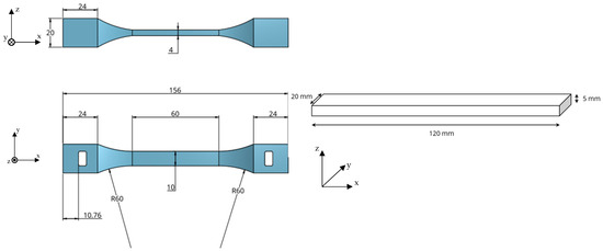
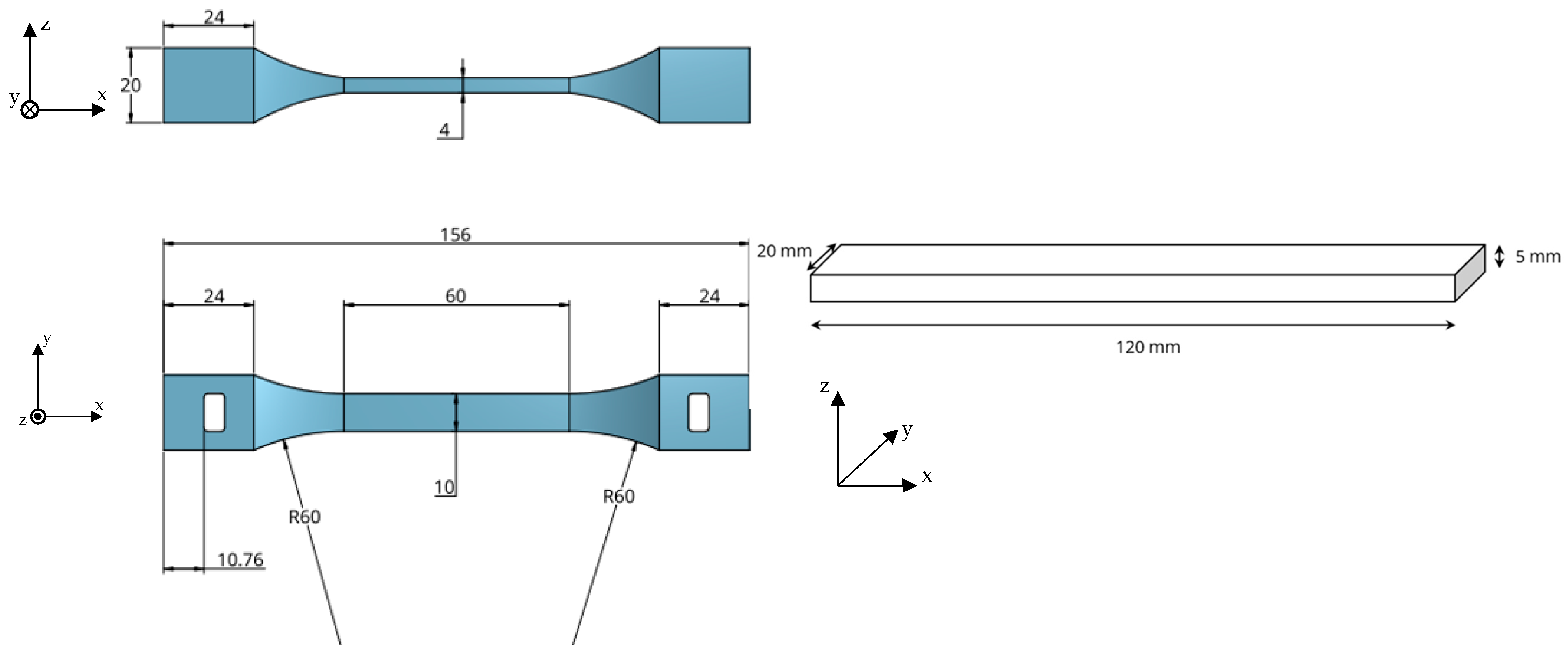
Two sets of samples were fabricated using FFF technology to evaluate mechanical performance under different loading conditions: tensile testing and three-point bending tests. For tensile testing, dog-bone-shaped specimens were designed following standardized geometries suitable for polymer mechanical characterization. Additionally, rectangular PLA plates were produced for the three-point bending tests, enabling the assessment of flexural properties. The schematic representations of both the tensile and bending test samples were prepared in CAD software and sliced using slicing software to generate printer instructions (Figure 1).
Figure 1.
Dog-bone sample geometry for tensile testing (left) and rectangular three-point bending sample dimensions (right).
2.2. Process Parameter Variation
A systematic experimental campaign was conducted to investigate the influence of key FFF process parameters on the mechanical response of PLA samples. The parameters that varied during fabrication included the nozzle’s diameter, the layer’s thickness, and the printing orientation. The nozzle’s diameter directly influences the material deposition rate, extrusion width, and interlayer bonding characteristics. The layer thickness is mostly related to the relationship between the layer resolution, surface quality, and mechanical integrity, whereas the printing orientation is critical for assessing the anisotropic behavior inherent to FFF-fabricated parts.
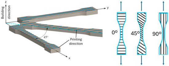
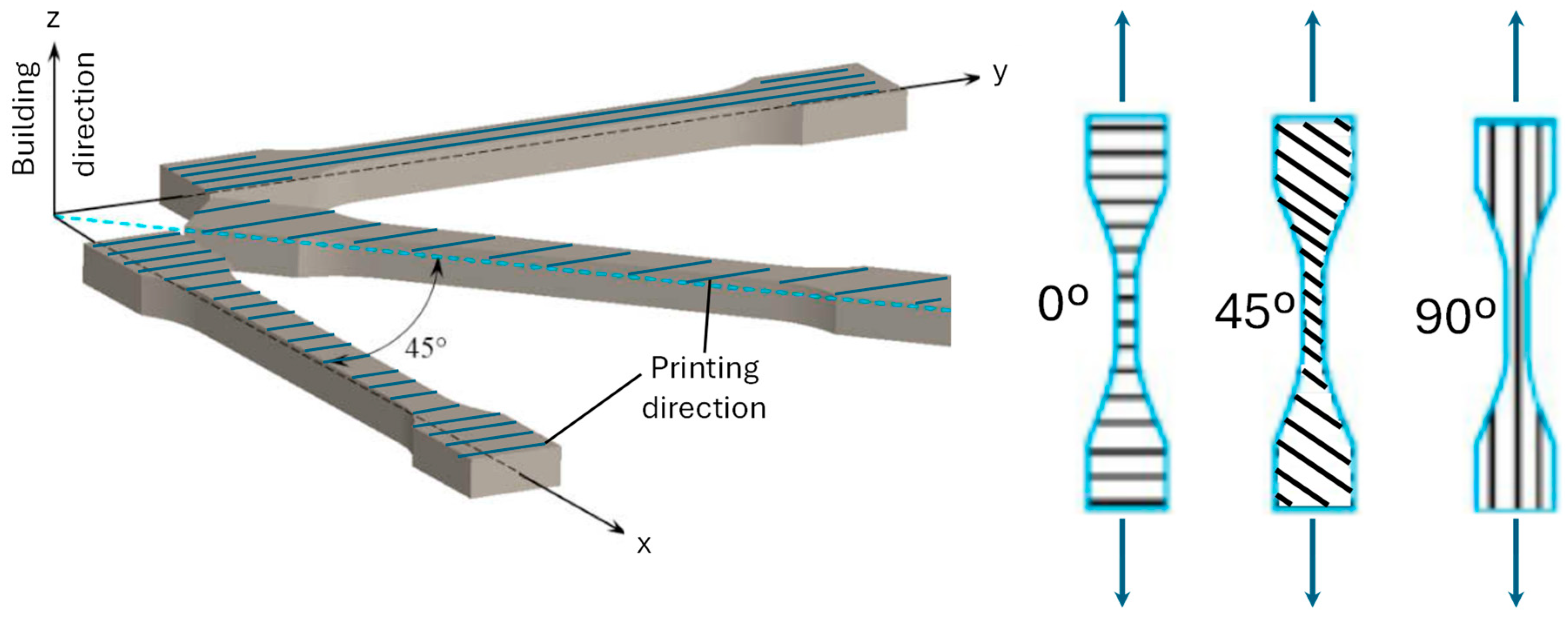
The experimental design enabled systematic evaluation of both individual parameter effects and their combined influence on the mechanical performance of PLA samples. The print speed of range 25–50 mm/s was selected in such a manner so that optimal deposition was achieved based on the machine setting recommendation for the set nozzle diameters (0.4 and 0.8 mm) and layer heights (0.16 and 0.32 mm) according to the literature [32,33,34]. All other printing conditions, including infill density and nozzle temperature, were held constant to isolate the effects of the selected process parameters. The process parameters used are presented in Table 2. The printing orientation angle was defined, as illustrated in Figure 2, with a 0° angle being transverse (short vectors) and 90° longitudinal (long vectors) to the tensile direction. In the case of three-point bending, a 0° printing angle was used parallel to the pins (short vectors) and 90° along the samples.
Table 2.
Applied FFF process parameters.
Figure 2.
Printing and testing orientation.
This structured approach provides a basic dataset with 12 configurations tested with two different methods (total of 24 experiments) for analyzing the relationships between FFF process parameters and mechanical response, facilitating the development of optimized printing strategies for PLA-based orthopedic applications.
3. Mechanical Testing and Experimental Results
Mechanical testing was conducted to assess the influence of FFF process parameters on the mechanical performance of PLA samples fabricated for potential orthopedic applications. Two mechanical loading conditions were evaluated: uniaxial tensile loading to determine tensile strength and stiffness, and three-point bending to assess flexural properties.
3.1. Static Tensile Testing
Static tensile testing was performed in accordance with ASTM D638, which specifies standard methods for determining the tensile properties of polymeric materials. Dog-bone-shaped PLA specimens were fabricated with varying process parameters, as described in Section 2, to assess the effects of the nozzle diameter, layer thickness, and printing orientation on tensile performance.
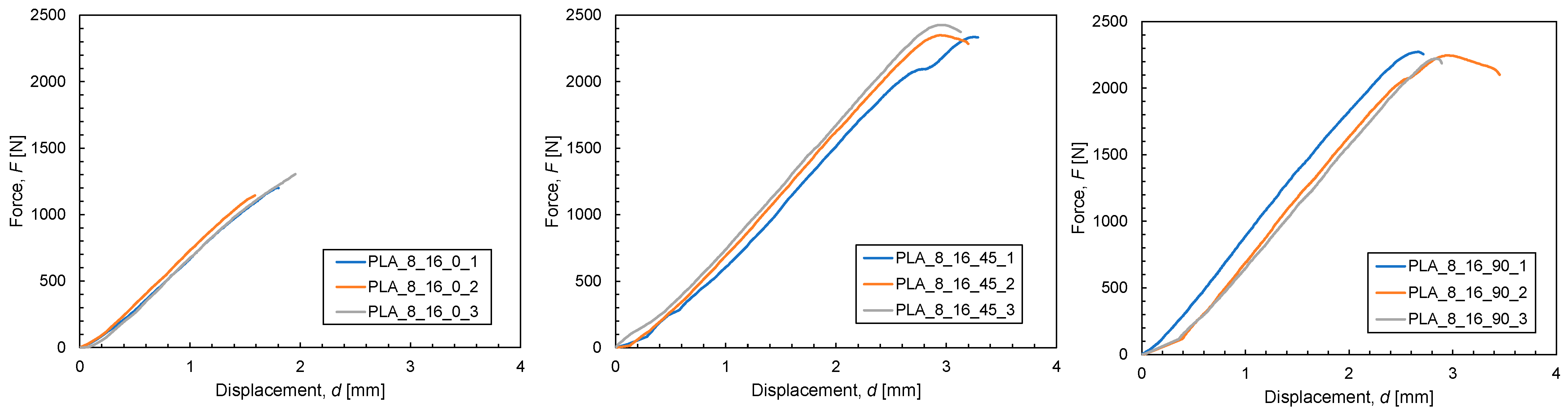
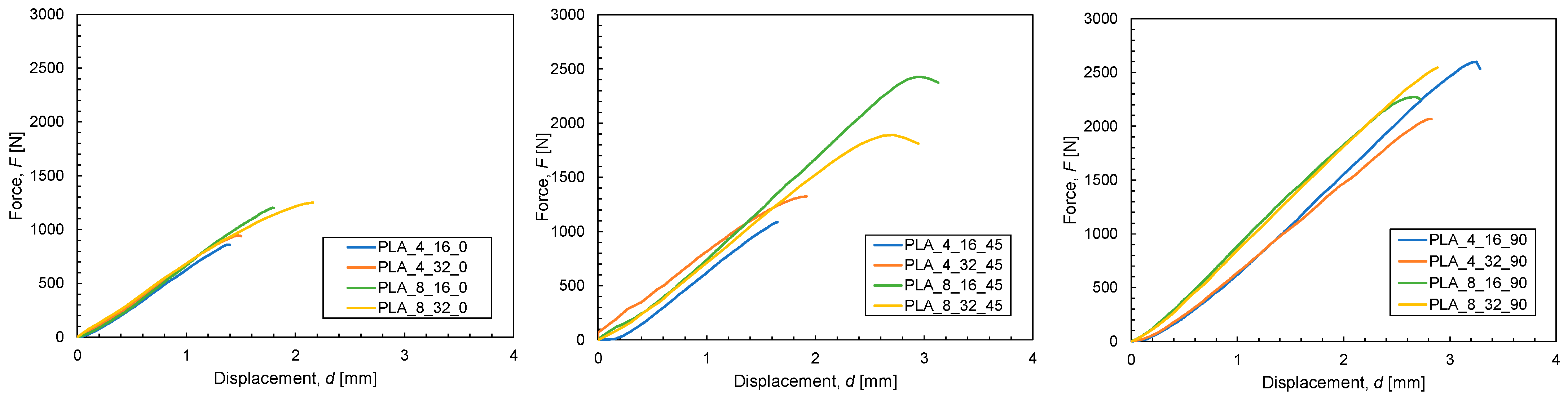
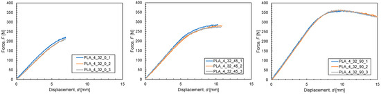
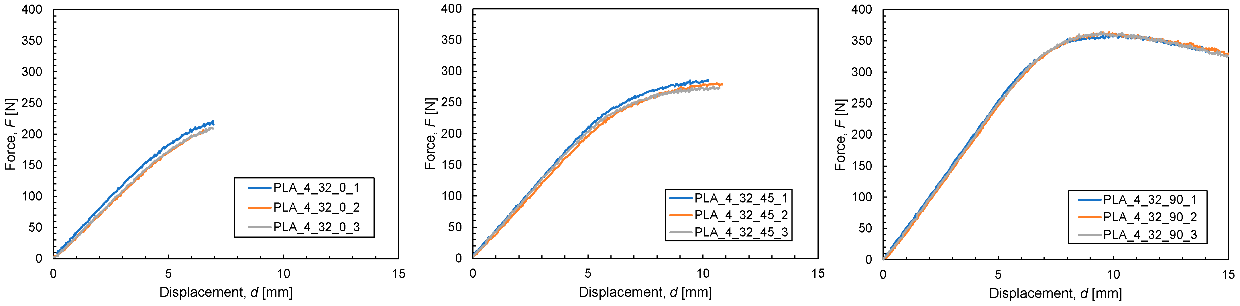
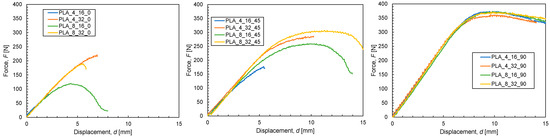
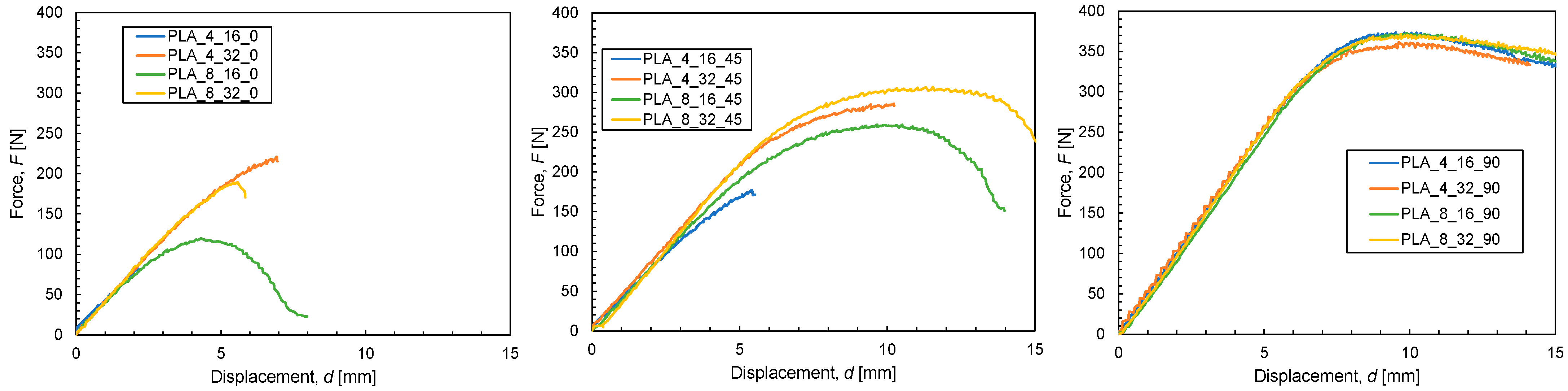
The tests were carried out using a custom-made testing machine setup equipped with a 5 kN load cell. A constant crosshead displacement rate of 5 mm/min was applied during testing, and the force displacement curves were recorded by data acquisition. For each parameter’s configuration, three specimens were tested to ensure statistical reliability. The captured force displacement diagrams of three exemplary parameter sets (nozzle diameter 0.8 mm and layer thickness 0.16 mm for the three orientation angles of 0°, 45°, and 90°) are illustrated in Figure 3, demonstrating a very good repeatability, whereas Figure 4 illustrates the total grouped results with respect to the deposition orientation angle using the middle graph of the three tested specimens.
Figure 3.
Force–displacement curves of tensile testing repeated with three specimens for selected parameter setups (nozzle diameter 0.8 mm and layer thickness 0.16 mm for the three orientation angles of 0°, 45°, and 90°), demonstrating very good repeatability.
Figure 4.
Force–displacement curves of tensile testing for the three orientation angles (0°, 45°, and 90°) with a changing nozzle diameter (0.4 and 0.8 mm) and layer thickness (0.16 and 0.32 mm).
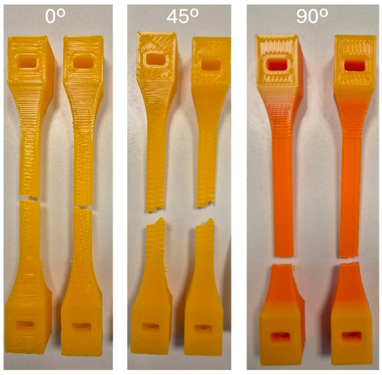
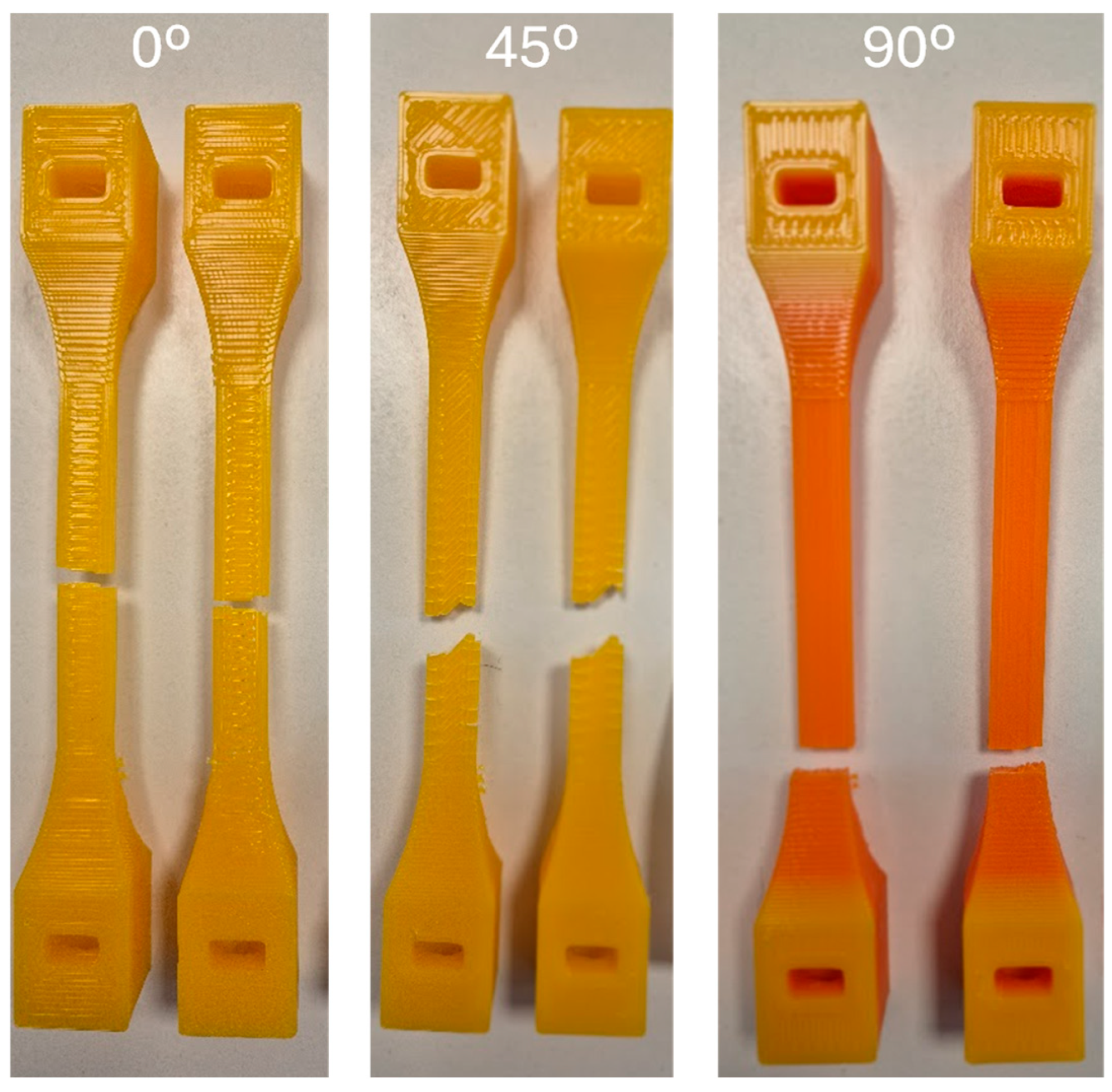
Figure 5 illustrates details of the exemplary tested tensile samples for the process parameter case with a nozzle diameter of 0.8 mm and layer thickness of 0.32 mm for the three orientation angles of 0°, 45°, and 90° (yellow-colored curves of Figure 4).
Figure 5.
Tested tensile samples and failure details fabricated with nozzle diameter of 0.8 mm and layer thickness of 0.32 mm for the three orientation angles of 0°, 45°, and 90°.
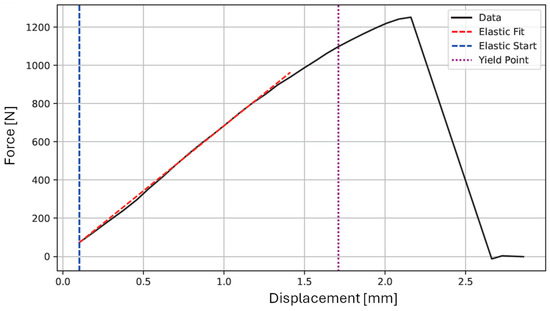
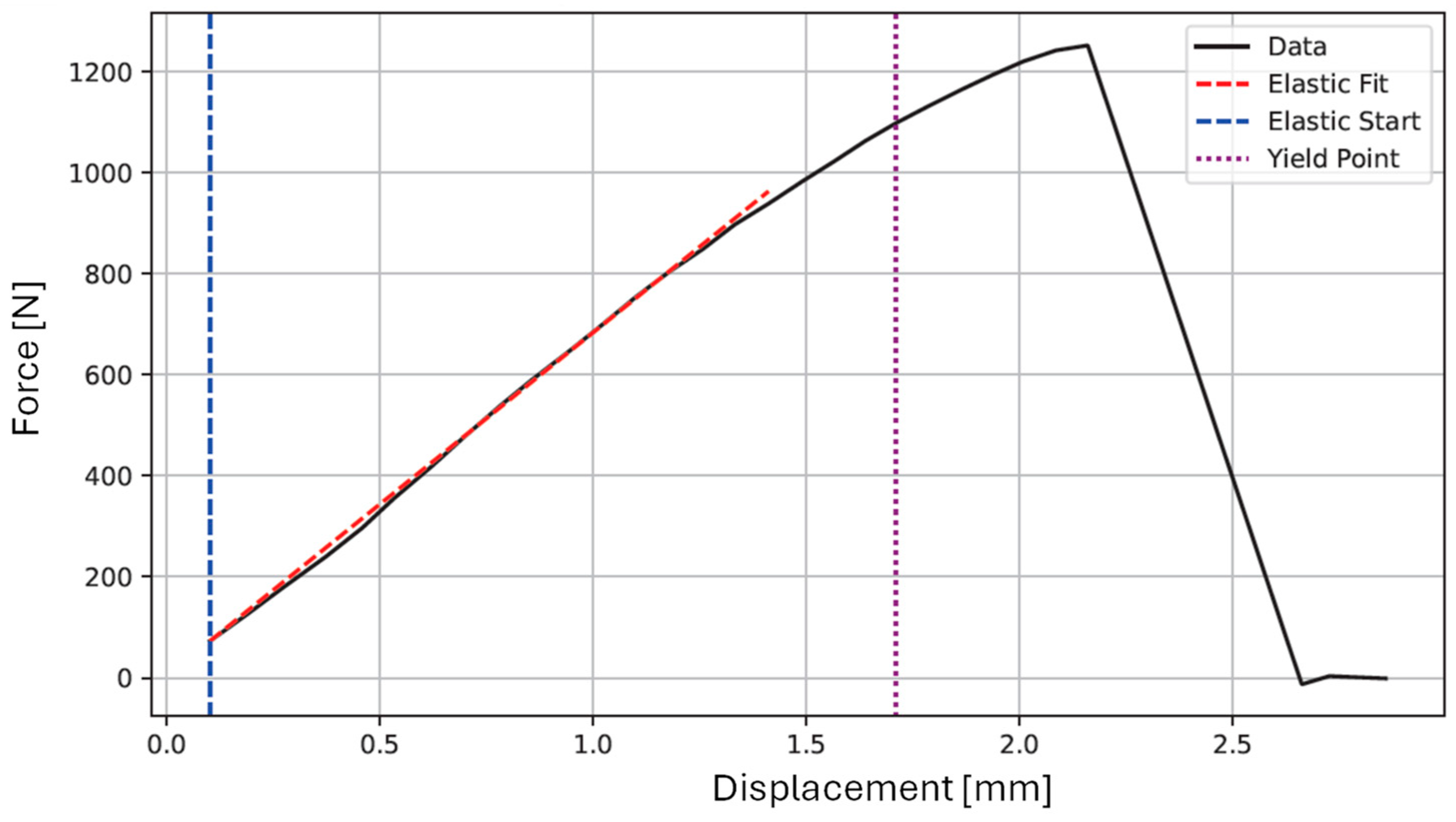
The recorded axial stiffness ka, i.e., slope, force at yield Fy, in the case of ductile behavior, and maximum force Fmax, of the curves were analyzed with the aid of an automated routine in PYTHON (version 3.8) to allow for a fast evaluation of the experimental outcomes (Table 3). Figure 6 indicates the features considered to evaluate the recorded force–displacement curves. The conditions for the slope calculation are an R2 > 0.999 and for the yield force to have the commencement of a nonlinearity > 5%. These metrics are indicative for the present case and will be reconsidered for future applications. Based on the recorded values, the average axial stiffness of the samples, i.e., slope, force at yield (for ductile behavior), and maximum force, were calculated (Table 4).
Table 3.
PYTHON algorithm for the automated evaluation of experimental results.
Figure 6.
PYTHON fitting routine for automated evaluation of stiffness (ka = 678.9 N/mm), yield (Fy = 678.9 N), and maximum force (Fmax = 1097.6 N) for sample 1 with nozzle diameter of 0.8 mm, layer thickness of 0.32 mm, and orientation angle of 0°.
Table 4.
Evaluated experimental results of tensile force–displacement curves with PYTHON routines.
Based on the experimental outcomes, the Young’s modulus E, yield stress σy, and maximum stress σmax, of the tensile samples for varying process parameters were calculated using the following equations, according to Gere (2012) [35]:
where A is the cross-section area and L is the length in the middle of the tensile samples, i.e., the region of a sample’s constant cross-section.
A correction factor kcor, was introduced to compensate for the displacement measurement error at and around the clamps. The correction factor, kcor, was calculated with the aid of finite element (FE) simulations with SolidWorks 2024. The calculated displacements on the tensile samples’ clamps replicating the testing setup were related to the displacements in the middle of the samples, i.e., the region of a constant cross-section, providing a correction factor kcor equal to 1.49. The final results of Young’s moduli E, yield stress σy, and maximum stress σmax, of the tensile testing are provided in Table 5.
Table 5.
Mechanical properties of PLA samples resulting from tensile testing.
The results revealed a strong dependence of tensile performance on FFF process parameters. Specifically, samples printed with lower layer thicknesses, i.e., 0.16 mm, exhibited improved tensile strength up to 65.2 MPa, exceeding the datasheet values provided in Table 1 by 40%, and Young’s modulus values of up to 2102 MPa, reaching 80% of the datasheet values, attributed to enhanced interlayer bonding and increased material continuity. Additionally, printing orientation significantly influenced mechanical anisotropy with a 90° orientation, i.e., parallel to the loading direction yielded the highest tensile strength and stiffness, while a 0° orientation, i.e., transverse to the loading direction, resulted in reduced mechanical performance.
3.2. Three-Point Bending Testing
Three-point bending tests were conducted according to ASTM D790 to evaluate the flexural behavior of PLA samples under bending loads, which simulate conditions commonly encountered in orthopedic devices and assistive structures. The rectangular plate specimens (Figure 1, right) were fabricated with the same parameter variations used in tensile testing. The tests were performed using a universal testing machine with a support span L of 82 mm, pin diameters of 24 mm, and a constant loading rate of 2 mm/min. For each parameter’s configuration, three specimens were tested, similar to tensile testing, to ensure statistical reliability. The captured force–displacement diagrams of three exemplary parameter sets under three-point bending (nozzle diameter of 0.4 mm and layer thickness of 0.32 mm for the three orientation angles of 0°, 45°, and 90°) are illustrated in Figure 7, demonstrating very good repeatability, whereas Figure 8 illustrates the total grouped results with respect to the deposition orientation angle using the middle graph of the three tested specimens.
Figure 7.
Force–displacement curves of three-point bending repeated with three specimens for selected parameter setups (nozzle diameter of 0.4 mm and layer thickness of 0.32 mm for the three orientation angles of 0°, 45°, and 90°), demonstrating very good repeatability.
Figure 8.
Force–displacement curves of bending testing for three orientation angles (0°, 45°, and 90°) with a changing nozzle diameter (0.4 and 0.8 mm) and layer thickness (0.16 and 0.32 mm).
Figure 9 illustrates details of the tested three-point bending samples exemplary for the process parameter case with a nozzle diameter of 0.8 mm and layer thickness of 0.32 mm for the three orientation angles of 0°, 45°, and 90°, demonstrating the brittle failure for a 0° orientation angle and the ductile behavior for the 45° and 90° orientation angles (yellow-colored curves of Figure 8).
Figure 9.
Tested three-point bending samples and failure details fabricated with nozzle diameter of 0.8 mm and layer thickness of 0.32 mm for the three orientation angles of 0°, 45°, and 90°.
The recorded flexural stiffness kb, i.e., slope, bending force at yield Fb,y, in the case of ductile behavior, and maximum bending force Fb,max, of the curves, were analyzed with the aid of an automated routine in PYTHON to allow for a fast evaluation of the experimental outcomes, similar to tensile testing (Figure 5). Based on the recorded values, the average flexural stiffnesses of the samples, i.e., slope, bending force at yield (for ductile behavior), and maximum bending force, were calculated (Table 6). The deflection at break was also recorded for samples, indicating a clear brittle fracture.
Table 6.
Evaluated experimental results of bending force–displacement curves with PYTHON routines.
Based on the experimental outcomes, the flexural modulus Eb, bending stress at yield σb,y, and maximum bending stress σb,max, of the bending samples for varying process parameters were calculated using the following equations, according to Gere (2012) [35]:
where w is the width and t is the thickness of the samples, whereas L is the length between the pin supports. The final results of flexural moduli Eb, bending stress at yield σb,y, and maximum bending stress σb,max, of the three-point bending tests are shown in Table 7.
Table 7.
Mechanical properties of PLA samples resulting from three-point bending testing.
The bending test results demonstrated trends consistent with tensile testing outcomes. The printing orientation played a critical role in flexural performance with the 90°-oriented samples, i.e., deposition on the samples’ long side, showing the highest flexural strength of 91.6 MPa, exceeding the datasheet value provided in Table 1 by more than 7%; the flexural modulus achieved a maximum of 2982 MPa, reaching 91% of the datasheet value, while the 0°-oriented specimens, i.e., deposition along the samples’ short side, exhibited lower structural integrity due to reduced interlayer bonding along the bending plane.
4. ANOVA Statistical Analysis and Discussion of Results
Analysis of Variance (ANOVA) was used to quantify the statistical influence of the three printing parameters—nozzle diameter (D), layer height (H), and printing orientation (θ)—on each mechanical response (slope, yield force, and maximum force). The analytical framework is based on, and extends, the methodology of Afrose et al. (2016) [36] who examined the influence of build orientation on tensile and fatigue performance of PLA using systematic comparisons across categorical process conditions. A completely randomized (CR) ANOVA analysis was proposed in the field of 3D printing and biomaterials by Fernández-Cervantes et al. (2019) [37]. ANOVA determines whether differences in the mean responses between levels of each factor are larger than would be expected from random experimental variability.
In the ANOVA model, each printing parameter appears as a categorical factor using the notation C(...): Nozzle diameter (D) is treated as two categories: 0.4 mm and 0.8 mm. Layer height (H) is two categories: 0.16 mm and 0.32 mm. Orientation (θ) is three categories: 0°, 45°, and 90°. By using categorical factors, the model does not treat these values as continuous numbers but only checks whether the average response differs between categories. The ANOVA model used is
where Y is the mechanical response (slope, yield force, or maximum force), μ is the overall average of the response, and D, H, and θ represent how each printing parameter shifts the response away from the overall average. ε represents the portion of the response that cannot be explained by the model.
Y = μ + D + H + θ + ε,
The explained variability (differences between groups) measures how much the mean value of each group differs from the overall (global) mean across all observations. It is calculated as
where the index denotes the group (or factor level), is the total number of groups, is the number of observations in group , is the mean of the observations in group , and is the global mean computed over all observations from all groups. The term weights the contribution of each group according to its sample size, so groups with more observations contribute more strongly. If a factor has a strong effect, the group means differ substantially from the global mean and this value becomes large.
The unexplained variability (random noise) measures how much individual measurements fluctuate within each group and is calculated as
where denotes the -th observation in the -th group and the index runs over all observations within group . This term quantifies variability within groups that cannot be attributed to differences between group means.
Degrees of freedom count the number of independent values used to estimate variability. For a factor with k levels, df_factor = k − 1. The residual degrees of freedom subtract model parameters from the total number of observations.
In ANOVA, the F-statistic is computed as F = MS_factor/MS_res. If the factor has no real effect, MS_factor and MS_res should be approximately equal, producing an F-value close to one. Larger F-values indicate that the factor explains more variation than would be expected from random noise alone. The p-value is then defined as the probability of observing an F-statistic at least as large as the one computed, assuming the factor truly has no effect; mathematically, it is the cumulative distribution function of the F-distribution with the appropriate numerator and denominator degrees of freedom. A small p-value means that such an extreme F-value would be very unlikely under the null hypothesis, indicating that the factor has a statistically significant influence on the response.
The ANOVA results demonstrate that printing orientation (θ) is by far the most significant factor affecting all mechanical responses, showing the largest sum of squares, highest F-values, and smallest p-values. This confirms that mechanical anisotropy in Fused Filament Fabrication is dominated by a road alignment relative to the loading direction. Layer height (H) exhibits a moderate effect, most pronounced in yield and maximum force, while nozzle diameter (D) shows only a weak influence across all responses. Across all responses, the ranking of factor importance is as follows:
- Printing orientation (dominant).
- Layer height (moderate).
- Nozzle diameter (weak).
Table 8 shows the ANOVA results evaluating the influence of nozzle diameter (C(D)), layer height (C(H)), and printing orientation (C(theta_f)) on the mechanical responses: slope, yield force, and maximum force. For each factor, sum_sq (sum of squares) quantifies how much variability in the response is explained by that factor, while df is the associated degrees of freedom. The F-value measures the ratio of explained variance to unexplained (residual) variance: a large F-value indicates that the factor produces changes in the response much greater than would be expected from random experimental noise. The corresponding PR(>F) is the p-value, representing the probability of observing such an F-value if the factor truly had no effect; thus, small p-values (typically <0.05) indicate a statistically significant influence, whereas large p-values suggest that the factor does not meaningfully affect the response. The mechanical responses are as follows: Slope—initial stiffness; Yield Force—onset of plastic deformation; and Maximum Force—peak load before failure. The Residual row reflects the variability not explained by the model.
Table 8.
Results of ANOVA statistical analysis.
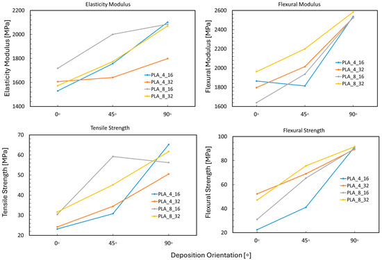
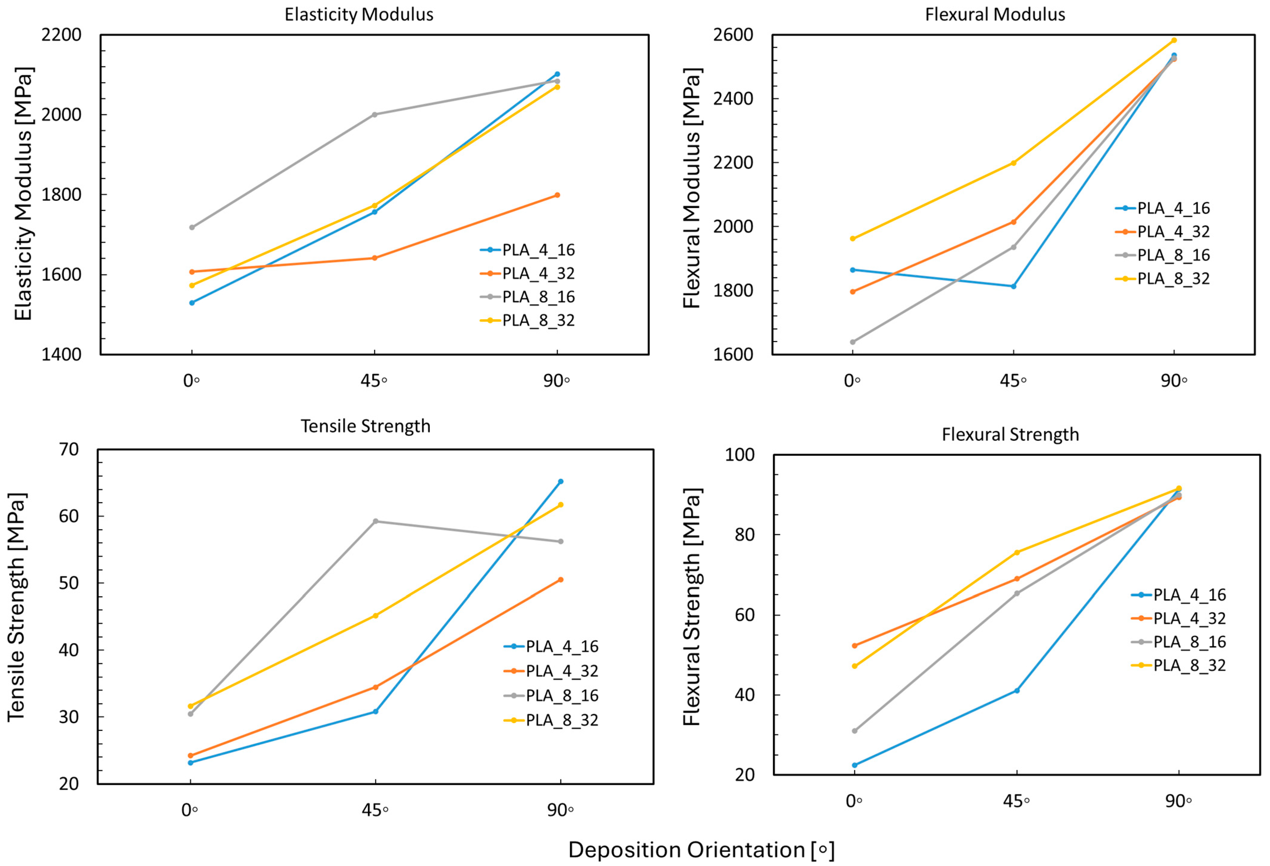
The printing orientation shows the most pronounced effect on all mechanical properties. Across both tensile and bending tests, samples printed at a 90° orientation (parallel to the load direction) exhibited superior stiffness and strength, as demonstrated in Figure 10. For instance, in tensile testing, PLA_4_16_90 samples showed the highest tensile strength (65.2 MPa) and PLA_8_32_90 samples reached a flexural strength of 91.6 MPa. These results confirm the anisotropic nature of FFF-printed PLA, where the alignment of printed paths with the load direction maximizes stress transfer through continuous polymer filaments and reduces interlayer failure.
Figure 10.
Summarized results.
Layer heigh exhibits a nonlinear trend on mechanical behavior. While thinner layers (0.16 mm) generally improved the tensile modulus and strength due to better bonding, their benefit was maximized only in conjunction with an optimal nozzle diameter and orientation. For instance, the PLA_8_16_90 configuration provided one of the best performances of tensile (65.2 MPa) and flexural strength (91.4 MPa), indicating that fine vertical resolution enhances structural coherence.
As far as the nozzle diameters are concerned, a larger nozzle (0.8 mm) predominately produced samples with better mechanical performance, particularly when paired with a lower layer thickness (0.16 mm) under tension and higher layer thickness (0.32 mm) under bending. This trend, visible in both the elasticity modulus and tensile strength plots, is attributed to improved interlayer bonding and reduced porosity. The combination of a 0.8 mm nozzle and 0.32 mm layer thickness yielded tensile strength exceeding 62 MPa and flexural strength over 91 MPa, suggesting that wider extrusion widths in combination with higher layer thicknesses do not exacerbate fusion between deposited layers and maintain mechanical continuities at a satisfactory level.
Finally, a strong agreement between tensile and bending test trends is observed, indicating that mechanical anisotropy is process-governed rather than test-mode specific. The best-performing samples across both load cases were consistently those printed with a 90° orientation, 0.8 mm nozzle diameter, and 0.16 mm layer thickness. These configurations provided both high stiffness and ductility, suggesting their applicability in functional orthopedic structures requiring load-bearing capabilities and patient-specific conformity.
5. Application on Orthopedic Wrist Splint Design
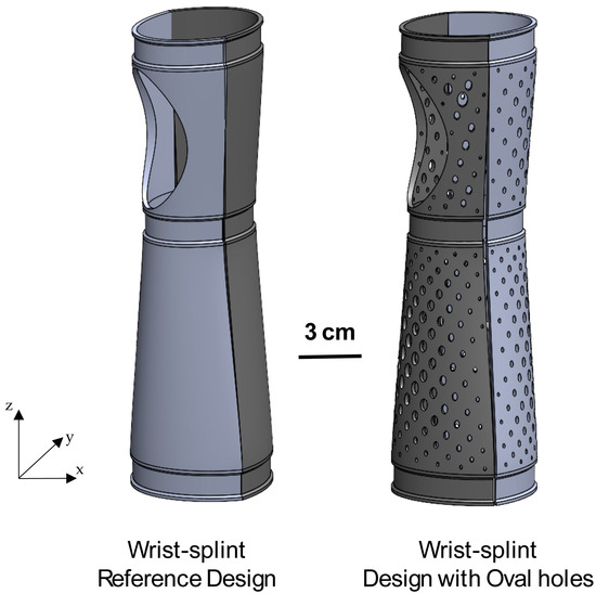
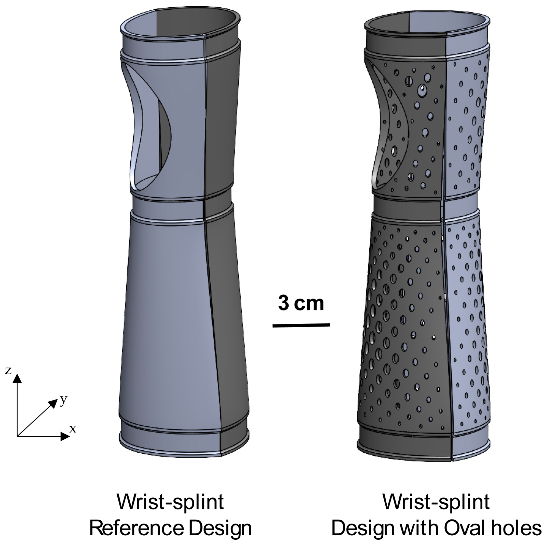
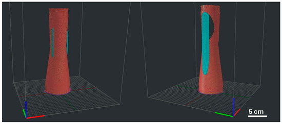
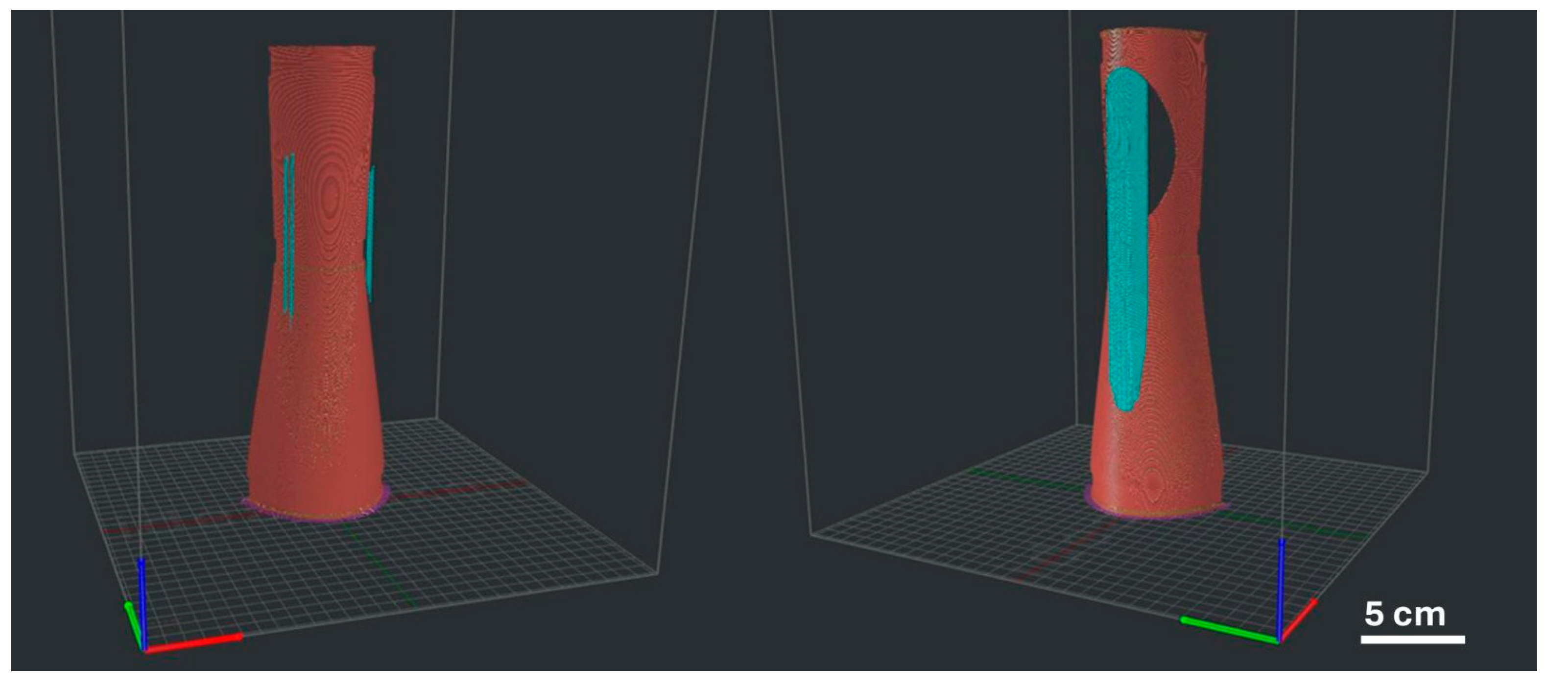
To demonstrate the results of the experimental investigation on orthopedic devices, two wrist splint design variations—a reference design and a design with ovals, each consisting of two components, full and with a hole—were drafted, as illustrated in Figure 11. The initial product requirements set concerns are moderate flexibility and sufficient strength under a maximum operation load of 500 N under three-point bending. In order to prepare for the 3D printing of the components, a vertical slicing is favored and performed with ideaMaker software (v. 4.1.1) to limit the need for support structures, as shown in Figure 12.
Figure 11.
Wrist splint design variants consisting of two components.
Figure 12.
Slicing model for WHS components.
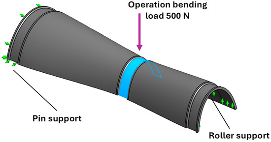
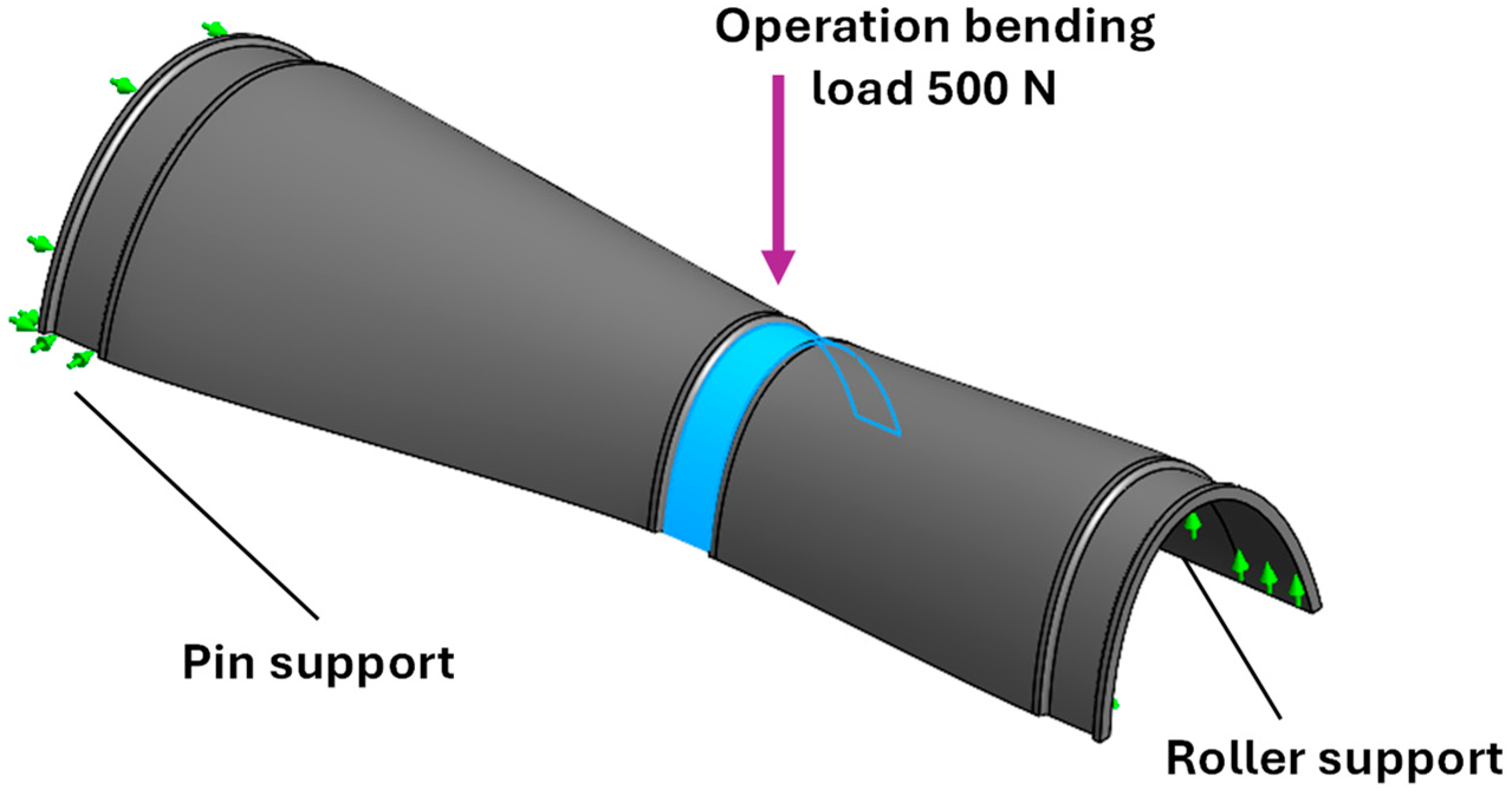
The preferred vertical slicing of the components implies the domination of the 0° printing orientation, i.e., in the building direction, when tested under three-point bending. For this reason, the material dataset of the θ = 0° printing orientation, D = 0.8 mm nozzle diameter, and H = 0.32 mm layer thickness were chosen for moderate flexural modulus and relatively good performing strength, while aiming at high deposition rates for faster fabrication. The four components were modeled and simulated by means of an elastic FE model in SolidWorks 2024 to predict their stiffness and strength performance during operation. The material properties corresponding to the selected parameter process set are shown in Table 9, whereas the lineal elastic FE model setup under a bending force of 500 N in SolidWorks 2024 is illustrated in Figure 13.
Table 9.
Material and plasticity properties for three-point bending simulation of wrist splint components.
Figure 13.
FE model setup in SolidWorks for the lineal elastic simulation of the wrist splint component design scenarios with green arrows indicating the defined support types.
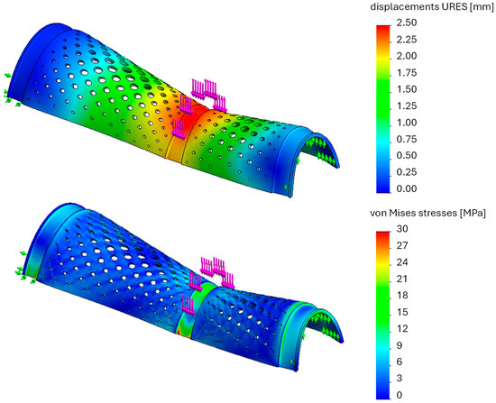
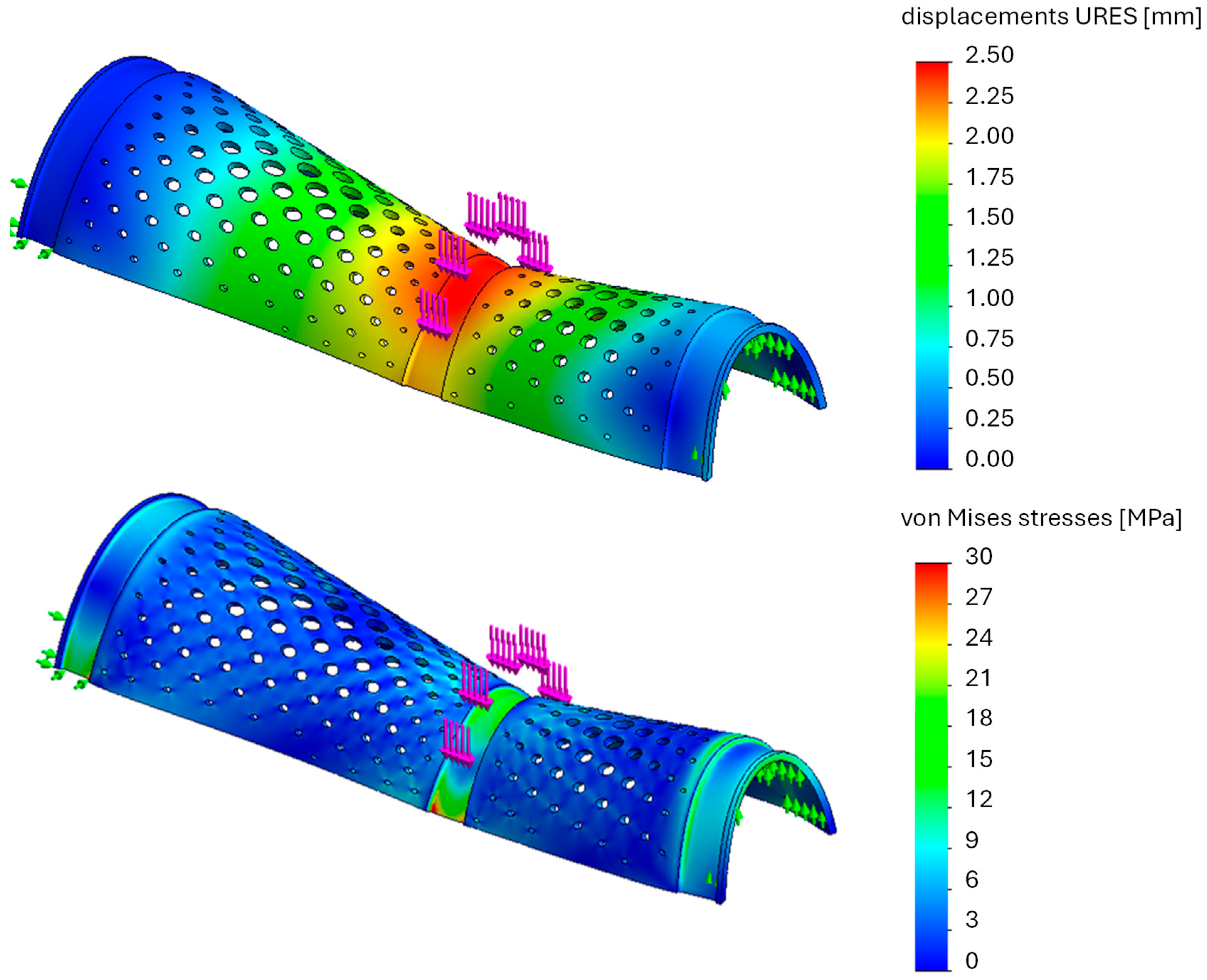
The results of the elastic FE analyses of the four components in terms of their deformation, flexural stiffness, and equivalent stresses with the von Mises criterion are shown in Table 10, whereas Figure 14 illustrates the deformation and von Mises stresses results of the FE analysis exemplary for the wrist splint design with ovals for the full component without a hole with the experimental material values.
Table 10.
FE simulation results of the wrist splint designs under bending loading.
Figure 14.
FE results of the deformation and von Mises stresses for the wrist splint design with ovals for the full component without a hole with pink arrows indicating an operation bending load of 500 N and the green arrows indicating the defined pin (left) and roller (right) supports.
The computational analysis of the designed components shows that introducing ovals increases deformation, i.e., flexibility, by approximately 15% in full components and up to 59% when a hole is present, compared with the reference design. Correspondingly, flexural stiffness decreases by about 13% for full components and 37% for components with a hole, while experiments confirm reductions of 11–12%. Maximum von Mises stresses remain comparable between designs for intact components, which was expected due to the linear elastic material formulation, and rise by about 5% when a hole is introduced, irrespective of geometry. On the one hand, linear elastic FE simulations systematically underpredict deformation, i.e., overpredict stiffness, when datasheet values are used, indicating the need for the application of realistic material properties depending on the fabrication parameters. On the other hand, a careful assessment of the actual material strength of the 3D-printed components is necessary, as the observed strength reduction may be critical under operational loading and should be explicitly accounted for in the refinement of the overall topological design. Overall, the oval design configuration imposes the possibility of adjusting the device’s flexibility and can be considered in stiffness-critical applications.
6. Conclusions and Future Work
This experimental study establishes a foundational understanding of how basic FFF parameters influence the mechanical response of PLA for orthopedic applications by systematically investigating the influence of major process parameters—nozzle diameter, layer thickness, and printing orientation—on the mechanical performance of PLA structures for orthopedic applications. The experimental results reveal a pronounced anisotropy governed primarily by printing orientation, which was identified through ANOVA as the dominant factor affecting stiffness, yield behavior, and ultimate strength. Samples printed at a 90° orientation consistently achieved the highest tensile and flexural performance, with maximum tensile strength reaching approximately 65 MPa and flexural strength exceeding 91 MPa, surpassing the corresponding datasheet values. Layer thickness exhibited a secondary but meaningful influence, with thinner layers (0.16 mm) generally improving interlayer cohesion and mechanical continuity. Nozzle diameter demonstrated a comparatively weaker effect, though larger extrusion widths (0.8 mm) improved performance when combined with optimized layer height and orientation.
Furthermore, the application of experimentally derived mechanical properties to the FE analysis of wrist splint designs demonstrated the necessity of using process-specific material data rather than datasheet values. Incorporating actual printed-material properties improved the accuracy of deformation and stiffness predictions, correcting the systematic overestimation observed when nominal properties were used. Design modifications involving oval openings enabled controlled flexibility adjustments with stiffness decreasing by 11–37%, depending on configuration, while careful consideration is required regarding the strength under critical loading due to possible strength reduction for particular printing parameter configurations, especially for a 0° orientation, i.e., transverse to the loading direction. These results highlight the combined influence of process parameters and topology on the structural behavior of additively manufactured orthopedic components.
Moreover, future investigations are identified to extend and deepen these findings. Future studies could incorporate additional process variables such as infill patterns, raster angles, build plate temperatures, and cooling rates, according to [31], and thereupon, explore the multi-objective optimization of these variables alongside structural anisotropy. These parameters could further refine the mechanical response and functional tuning of PLA structures. Real-life orthopedic applications involve cyclic loading and dynamic impacts. Thus, extending mechanical evaluation to include fatigue behavior and impact resistance will offer a more complete performance profile. Furthermore, the anisotropic mechanical response findings depending on the process parameter combination will be supported with further filament materials and fabrication parameters—infill strategies, further nozzle diameters, and thermal post-treatments—for a more representative statistical analysis. The extended experimental findings can be incorporated into material definitions for nonlinear FE analyses including failure prediction models and topology optimization of future orthopedic device designs with the use of different lattice architectures.
Finally, Machine Learning-based optimization is planned to be developed based on an enhanced established experimental dataset [38]. A neural network-based substitution model will be trained to predict mechanical outcomes based on input parameters, helping to automate the design optimization loop and reduce trial-and-error fabrication and experimentation [39].
Author Contributions
Conceptualization, D.P. and L.P.; methodology, D.P. and L.P.; software, T.L. and L.P.; validation, S.A., T.L., and L.P.; formal analysis, S.A., D.P., T.L., and L.P.; investigation, S.A., D.P., and L.P.; resources, S.A., D.P., T.L., and L.P.; data curation, S.A., T.L., and L.P.; writing—original draft preparation, S.A., D.P., T.L., and L.P.; writing—review and editing, S.A., D.P., and L.P.; visualization, S.A., T.L., and L.P.; supervision, L.P.; project administration, D.P., S.A., and L.P.; funding acquisition, D.P., S.A., and L.P. All authors have read and agreed to the published version of the manuscript.
Funding
This work is part of the research conducted under the project PHD IN INDUSTRY/1222/0073, which is funded by the Republic of Cyprus, through the Research and Innovation Foundation.
Data Availability Statement
The data presented in this study are available on request from the corresponding author due to commercial product sensitivity.
Conflicts of Interest
Authors Stelios Avraam and Demetris Photiou were employed by the company Simlead Ltd. The remaining authors declare that the research was conducted in the absence of any commercial or financial relationships that could be construed as a potential conflict of interest.
References
- Ramakrishna, S.; Mayer, J.; Wintermantel, E.; Leong, K.W. Biomedical Applications of Polymer-Composite Materials: A Review. Compos. Sci. Technol. 2001, 61, 1189–1224. [Google Scholar] [CrossRef] [Scilit]
- Henderson, C.J.; Ji, Z.; Zou, M.; Hua, X.; Stone, T.; Pattinson, S.W. Lightweight and High-Performance Ankle Braces Enabled by 3D Printed Metamaterial Liquid Crystal Polymer. Adv. Mater. Technol. 2025, 10, e00729. [Google Scholar] [CrossRef] [Scilit]
- Raziyan, M.S.; Palevicius, A.; Perkowski, D.; Urbaite, S.; Janusas, G. Development and Evaluation of 3D-Printed PLA/PHA/PHB/HA Composite Scaffolds for Enhanced Tissue-Engineering Applications. J. Compos. Sci. 2024, 8, 226. [Google Scholar] [CrossRef] [Scilit]
- ISO/ASTM 52900:2021; Terminology for Additive Manufacturing—General Principles—Terminology. ISO: Geneva, Switzerland, 2021.
- Chalgham, A.; Ehrmann, A.; Wickenkamp, I. Mechanical Properties of Fdm Printed Pla Parts before and after Thermal Treatment. Polymers 2021, 13, 1239. [Google Scholar] [CrossRef] [Scilit]
- Kelly, C.; Adams, S.B. 3D Printing Materials and Technologies for Orthopaedic Applications. J. Orthop. Trauma 2024, 38, S9–S12. [Google Scholar] [CrossRef] [Scilit]
- Cong, B.; Zhang, H. Innovative 3D Printing Technologies and Advanced Materials Revolutionizing Orthopedic Surgery: Current Applications and Future Directions. Front. Bioeng. Biotechnol. 2025, 13, 1542179. [Google Scholar] [CrossRef] [Scilit] [PubMed]
- Wielgus, G.; Kajzer, W.; Kajzer, A. The Use of Non-Degradable Polymer (Polyetheretherketone) in Personalized Orthopedics—Review Article. Polymers 2025, 17, 2158. [Google Scholar] [PubMed]
- Kotteda, A.K.; Saikumar, T.; Shreegan, A.A. Advancements in Biodegradable Orthopaedic Implants: A Literature Review. Indian J. Orthop. 2025, 59, 1090–1100. [Google Scholar] [CrossRef] [Scilit]
- Chen, M.Q. Recent Advances and Perspective of Nanotechnology-Based Implants for Orthopedic Applications. Front. Bioeng. Biotechnol. 2022, 10, 878257. [Google Scholar] [CrossRef] [Scilit] [PubMed]
- Middleton, J.C.; Tipton, A.J. Synthetic Biodegradable Polymers as Orthopedic Devices. Biomaterials 2000, 21, 2335–2346. [Google Scholar] [CrossRef] [Scilit]
- Wang, A.; Stark, C.; Dumbleton, J.H. Mechanistic and Morphological Origins of Ultra-High Molecular Weight Polyethylene Wear Debris in Total Joint Replacement Prostheses. Proc. Inst. Mech. Eng. Part H 1996, 210, 141–155. [Google Scholar] [CrossRef] [Scilit]
- Hossain, M.T.; Shahid, M.A.; Mahmud, N.; Habib, A.; Rana, M.M.; Khan, S.A.; Hossain, M.D. Research and Application of Polypropylene: A Review. Discov. Nano 2024, 19, 2. [Google Scholar] [CrossRef] [Scilit] [PubMed]
- Sarwar, M.A.; Stampone, N.; Usman, M. From Static to Adaptive: A Systematic Review of Smart Materials and 3D/4D Printing in the Evolution of Assistive Devices. Actuators 2025, 14, 483. [Google Scholar] [CrossRef] [Scilit]
- Popescu, D.; Zapciu, A.; Amza, C.; Baciu, F.; Marinescu, R. FDM Process Parameters Influence over the Mechanical Properties of Polymer Specimens: A Review. Polym. Test. 2018, 69, 157–166. [Google Scholar] [CrossRef] [Scilit]
- Ramírez-Prieto, J.S.; Martínez-Yáñez, J.S.; González-Hernández, A.G. Effect of Raster Angle on the Tensile and Flexural Strength of 3D Printed PLA+ Parts. AIMS Mater. Sci. 2025, 12, 363–379. [Google Scholar] [CrossRef] [Scilit]
- Yang, Y.; Wang, C.; Wang, Y.; Xue, B.; Kong, D. Research on Effects of FDM Process Parameters on Mechanical Properties of Polylactic Acid Based on Orthogonal Experiments. Preprints 2024, 2024120097. [Google Scholar] [CrossRef] [Scilit]
- Yang, Y.; Wang, Y.; Xue, B.; Wang, C.; Yang, B. Optimization of FDM Process Parameters for Mechanical Properties of Aerospace Parts Based on Kriging and CS. Preprints 2024, 2024120111. [Google Scholar] [CrossRef] [Scilit]
- Tymrak, B.M.; Kreiger, M.; Pearce, J.M. Mechanical Properties of Components Fabricated with Open-Source 3-D Printers under Realistic Environmental Conditions. Mater. Des. 2014, 58, 242–246. [Google Scholar] [CrossRef] [Scilit]
- Gao, Z.; Han, Z.; Fu, Y.; Zhao, X.; Lv, H.; Li, M.; Zhu, J. Investigation of Process Parameters on Three Dimensional Printed Composites Tensile Performance Boosted by Attention Mechanism-Enhanced Multi-Modal Convolutional Neural Networks. SSRN 2025, 58, 242–246. [Google Scholar] [CrossRef] [Scilit]
- Karthick, R.; Anbumalar, V.; Jeyakumar, R.; Kubendiran, M.; Kevin Jasper, S.; Sankara Pandian, D.; Manish Kumar, D. Mechanical Properties of Novel Polylactic Acid-3D Printed Core/Aloevera/Glass Fiber Reinforced Hybrid Composites. In Advances in Additive Manufacturing Technologies; Gurusamy, P., Ed.; CRC Press: London, UK, 2024; ISBN 9781003545774. [Google Scholar]
- Nagaraju, P. 4D Printing of PLA and PLA-Based Composites for Load-Bearing Applications. Master’s Thesis, Department of Mechanical Engineering, Cleveland State University, Cleveland, OH, USA, 2020. [Google Scholar]
- Kumar Madheswaran, S.; Venkatesh Raja, K. Assessment on the Influence of FDM Process Parameters on the Mechanical Properties of PLA Samples. Int. J. Mater. Res. 2024, 115, 752–766. [Google Scholar] [CrossRef] [Scilit]
- Axinte, M.; Chicet, D.L.; Chelariu, R.; Comăneci, R.I. The Influence of Processing Parameters on the Mechanical Properties of PLA 3D Printed Parts. Arch. Metall. Mater. 2024, 69, 1621–1627. [Google Scholar] [CrossRef] [Scilit]
- Pandey, D.; Pandey, R.; Tewari, R.P. Influence of Process Parameters on Mechanical Strengths of 3d-Printed Carbon-Pla Based Composites for Orthotics and Prosthetics Applications. Compos. Mech. Comput. Appl. Int. J. 2023, 14, 29–38. [Google Scholar] [CrossRef] [Scilit]
- Ghaffar, A. Correlating FDM Printing Parameters with Mechanical Properties and Surface Quality of PLA Printouts. Eng. Res. Express 2024, 6, 045538. [Google Scholar] [CrossRef] [Scilit]
- Photiou, D.; Avraam, S.; Sillani, F.; Verga, F.; Jay, O.; Papadakis, L. Experimental and Numerical Analysis of 3d Printed Polymer Tetra-Petal Auxetic Structures under Compression. Appl. Sci. 2021, 11, 10362. [Google Scholar] [CrossRef] [Scilit]
- Valerga, A.P.; Batista, M.; Salguero, J.; Girot, F. Influence of PLA Filament Conditions on Characteristics of FDM Parts. Materials 2018, 11, 1322. [Google Scholar] [CrossRef] [Scilit]
- ASTM D638-14; Standard Test Method for Tensile Properties of Plastics. ASTM International: West Conshohocken, PA, USA, 2014.
- ASTM D790-20; Standard Test Methods for Flexural Properties of Unreinforced and Reinforced Plastics and Electrical Insulating Materials. ASTM International: West Conshohocken, PA, USA, 2020.
- Dhinesh, S.K.; Arun Prakash, S.; Senthil Kumar, K.L.; Megalingam, A. Study on Flexural and Tensile Behavior of PLA, ABS and PLA-ABS Materials. Mater. Today Proc. 2021, 45, 1175–1180. [Google Scholar]
- Jatti, V.S.; Sapre, M.S.; Jatti, A.V.; Khedkar, N.K.; Jatti, V.S. Mechanical Properties of 3D-Printed Components Using Fused Deposition Modeling: Optimization Using the Desirability Approach and Machine Learning Regressor. Appl. Syst. Innov. 2022, 5, 112. [Google Scholar] [CrossRef] [Scilit]
- Grubbs, J.; Sousa, B.C.; Cote, D.L. Establishing a Framework for Fused Filament Fabrication Process Optimization: A Case Study with PLA Filaments. Polymers 2023, 15, 1945. [Google Scholar] [CrossRef] [Scilit]
- Goulas, A.; Zhang, S.; McGhee, J.R.; Cadman, D.A.; Whittow, W.G.; Vardaxoglou, J.C.; Engstrøm, D.S. Fused Filament Fabrication of Functionally Graded Polymer Composites with Variable Relative Permittivity for Microwave Devices. Mater. Des. 2020, 193, 108871. [Google Scholar] [CrossRef] [Scilit]
- Gere, J.M.; Goodno, B.J. Mechanics of Materials; Cengage Learning: Boston, MA, USA, 2012; ISBN 1111577730. [Google Scholar]
- Afrose, M.F.; Masood, S.H.; Iovenitti, P.; Nikzad, M.; Sbarski, I. Effects of Part Build Orientations on Fatigue Behaviour of FDM-Processed PLA Material. Prog. Addit. Manuf. 2016, 1, 21–28. [Google Scholar] [CrossRef] [Scilit]
- Fernández-Cervantes, I.; Morales, M.A.; Agustín-Serrano, R.; Cardenas-García, M.; Pérez-Luna, P.V.; Arroyo-Reyes, B.L.; Maldonado-García, A. Polylactic Acid/Sodium Alginate/Hydroxyapatite Composite Scaffolds with Trabecular Tissue Morphology Designed by a Bone Remodeling Model Using 3D Printing. J. Mater. Sci. 2019, 54, 9478–9496. [Google Scholar] [CrossRef] [Scilit]
- Aktepe, E.; Ergün, U. Machine Learning Approaches for FDM-Based 3D Printing: A Literature Review. Appl. Sci. 2025, 15, 10001. [Google Scholar] [CrossRef] [Scilit]
- Deka, A.; Hall, J. Manufacturing Letters Predictive Modeling of Mechanical Properties for Fused Deposition Modeling Parts: A Focus on Processing and Environmental Parameters-NC-ND License (Https://Creativecommons.Org/Licenses/by-Nc-Nd/4.0) Peer-Review under Responsibility of the Scientific Committee of the NAMRI/SME. Manuf. Lett. 2023, 35, 643–651. [Google Scholar]



Disclaimer/Publisher’s Note: The statements, opinions and data contained in all publications are solely those of the individual author(s) and contributor(s) and not of MDPI and/or the editor(s). MDPI and/or the editor(s) disclaim responsibility for any injury to people or property resulting from any ideas, methods, instructions or products referred to in the content. |
© 2025 by the authors. Licensee MDPI, Basel, Switzerland. This article is an open access article distributed under the terms and conditions of the Creative Commons Attribution (CC BY) license (https://creativecommons.org/licenses/by/4.0/).