


Abstract
Computed tomography and magnetic resonance imaging are two powerful modalities which can be used in the clinical setting to produce data for the creation of patient-specific finite element analysis (FEA) models and physical analogues—for instance, by using additive manufacturing (AM)—that mimic the properties of soft and hard tissues, both morphologically and mechanically. However, there remains a gap between creating a perfect biofidelic physical analogue and its computational counterpart. This gap exists because, firstly, in silico models are often too complex to realise, and secondly, real-life conditions are challenging to emulate both computationally and mechanically, as they involve multiscale situations that are inherently heterogeneous and patient specific. In this study, we applied a multi-scale approach to design and model porcine vertebral specimens. Our results identified critical design factors that affect the quality and accuracy of the models, specifically highlighting that scanning resolution/fidelity and the thresholding technique have a directly proportional impact on model accuracy. A small shift up and down the greyscale level by 20 units can affect the behaviour of the AM sample by as much as [−15% +47%]. Working up the levels for manufacturing, testing and modelling (i) cylindrical cores to (ii) whole vertebrae and then (iii) a whole spine motion segment, we observed that the fidelity of predictions reduces, and errors increase as the structure becomes more complicated and intricate (3.6%, 7.5% and 15%, respectively). We are confident that further material-level developments will provide solutions for the more intricate parts of spinal motion segments, such as the intervertebral discs and facets, which in their natural form are highly sophisticated structures. To the best of our knowledge, this is the first time a holistic multiscale approach has been implemented to produce AM biofidelic analogues of skeletal parts. Our data showed good agreement between the physical and in silico models, confirming that it is possible to model real-time objects and situations both physically and in silico. This ultimately will enable the development of accurate, patient-specific physical models for use in biomechanical testing and medicolegal applications.
1. Introduction
The combination of additive manufacturing and increasing computational power has introduced new concepts in the development of biomechanical analogues and corresponding models, allowing for the creation of robust in silico and physical models that overcome the complex ethical procedures concerning the use of cadaveric specimens. Rapid prototyping and 3D printing has proved invaluable in biomedical engineering, orthopaedic surgery and clinical education [1,2,3,4,5,6], and in forensic applications by offering physical size models which can be handled and used to demonstrate structure and materials [7,8]. Finite element analysis, in particular, has facilitated the characterisation and testing of different components of the musculoskeletal system [9]. This evolution in computational and screening techniques has driven research towards complex and unknown territory [10,11], where bone macro-modelling is increasingly replaced by highly detailed and resource heavy micro-scale models [12]. The creation of biofidelic models, whether in silico or in real life, is more complex when investigating intricate geometries where the interactions between different subcomponents (such as soft and hard tissues) play a key role [13]. The reliability of such models depends heavily on how they are defined, interpreted and implemented for each application. These definitions are based on approximations and compromises limited by technical and resource constraints such as 3D printing resolution, scanning capability and the trade-off between computational speed and accuracy [10,12,13,14].
1.1. Recent Applications—Skull
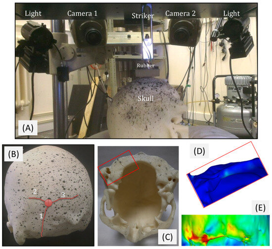
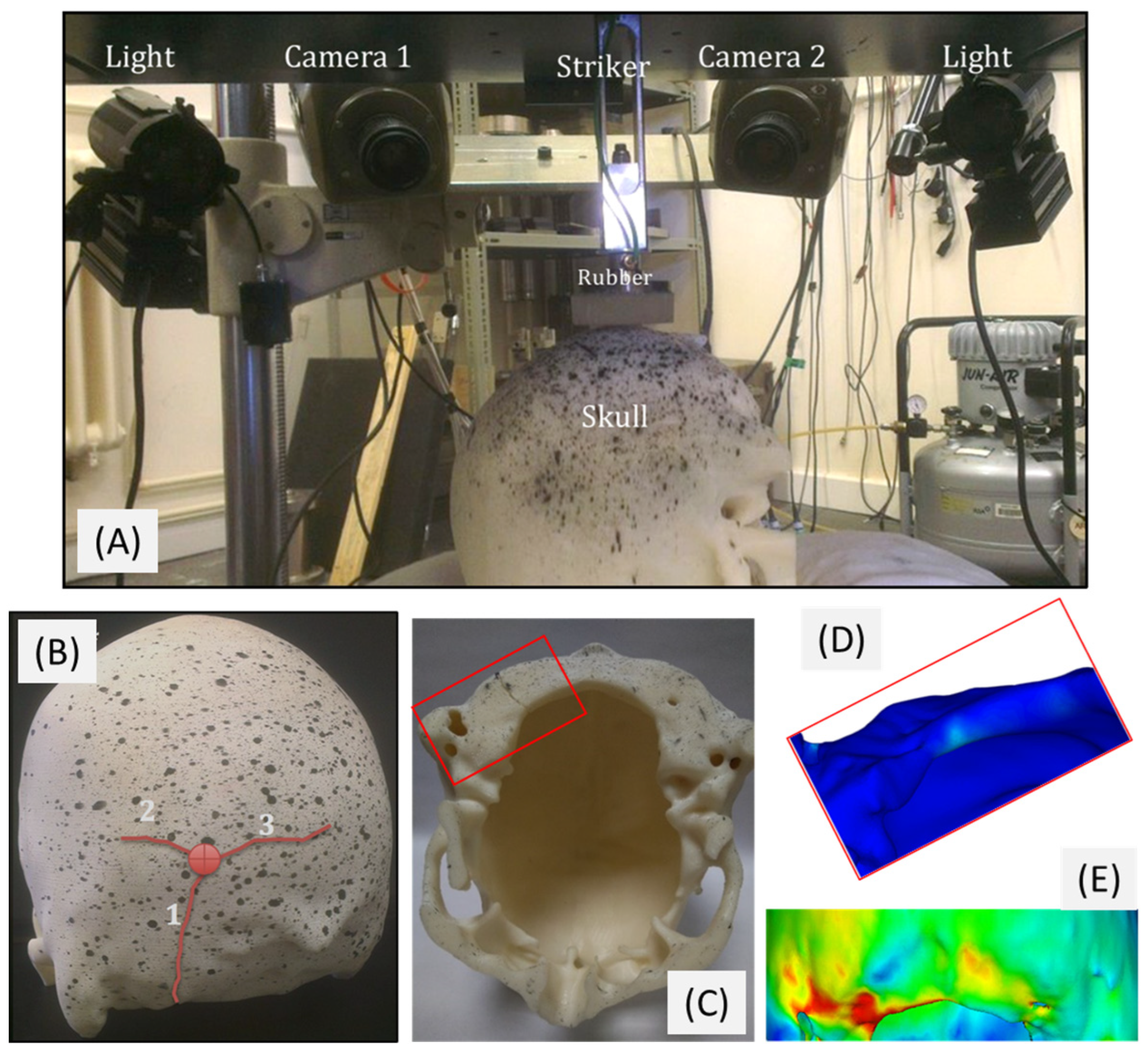
We have recently used a combination of 3D printing and FEA (finite element analysis) modelling to study skull fractures in impact [15,16]. The results were remarkably reproducible and offered insight in fracture scenarios, where if one used real tissue samples, every test would yield a different outcome. By producing many copies of the same skull (reproducing the geometry accurately with exactly the same material each time), it is possible to observe if a fracture pattern, fracture being a stochastic event, is a result of the bone material heterogeneity, the bone structure, or both. Two aspects of the skull fracture were particularly revealing: firstly, the cracks emanating from the impact site were always of the same pattern and directionality in every test, indicating that the crack progress had more to do with the structure and geometry of the skull than what it was made of, and secondly, smaller cracks at the base of the skull were at the same site in the various tests and also where FEA models were predicting them to be (Figure 1).
Figure 1.
An example of a holistic approach involving the creation of both a physical model and an in silico (computational) model of a human skull, as studied in [15,16]. (A) A number of replicas of the skull were impacted at the same point in a drop tower, suitable illumination and high speed cameras were used, full details in [15,16]; (B) crack patterns at the site of impact were emanating in 3 diverging crack routes, which were identical in all replicas of the skull used [15]; (C) other cracks at the base of the skull (red square) appeared reliably and repeatedly in certain areas and where FEA modelling predicted them to appear (enlarged views of the area in (D,E)), showing a synergy and agreement between these two powerful biomechanical testing methodologies (AM produced physical model and in silico computational model).
1.2. Recent Applications—Vertebrae
In spine biomechanics, motion segment analogues have been produced with varying levels of success [17,18]. Outsourcing the development of custom analogues requires several months of lead time and involves prohibitive costs and ethical restrictions, which limit their accessibility. These analogues are produced mostly for demonstration and training purposes, and as such do not fully simulate the mechanical behaviour of the natural parts they represent. Biofidelic copies of vertebrae and spine motion segments have been validated by quasi-static compression loading in vitro [19]. 3D-printed analogues were created using readily available and off-the-shelf materials with known mechanical properties: namely, acrylonitrile butadiene styrene (ABS) for the vertebral body and a two-part liquid polyurethane rubber system (of an appropriate Shore hardness value) for the intervertebral disc (IVD) and the superior and inferior process ligaments [19,20,21].
1.3. The Need for Multilevel Validation
The present study explores the potential of finite element analysis (FEA) for the modelling and validation of 3D-printed spinal analogues under quasi-static loading (0.01 mm/s), which is investigated using a bottom-up approach (from small sample size and increasing the length scale) instead of the top-down strategy applied in other multiscale studies [22,23]. This would allow us to determine the lowest fidelity needed to provide an effective method for the validation of the physical model, thus reducing the costs and lead time for a patient-specific FEA solution. A biofidelic finite element model must be fed with material properties in order to calculate accurate stresses and strains. The assignment of these properties at the microscopic scale is derived from measurement at this level, which usually involves a surrogate physical variable such as the micro-CT greyscale (GS). This is dependent on the linear attenuation coefficient of the material, which is linked to the material density.
In order to generate a material model for ABS over a wide applicable range (micro to macro), there needs to be a discernible variation in the average GS values between samples. Here, we achieved this in three steps by testing specimens with (1) longitudinal holes in solid cores (longitudinal cores), (2) solid, high-density and low-density filled cores (transverse cores), and (3) artificial vertebral cores (AVCs) with varying threshold levels. The most accurate material model was selected and applied to higher-scale segments: (1) an artificial vertebral body (AVB) and (2) an artificial motion segment (AMS), comprising two vertebrae with the intervertebral disc (IVB) in between, as described in our previous work [20,21]. We have thus investigated the best practices for generating an FEA model of a physical analogue that is suitable for multiscale analysis, ultimately aiming to facilitate the development of patient-specific tissue (and bone tissue, for that matter) analogues which can be used in orthopaedic and biomechanical applications.
2. Materials and Methods
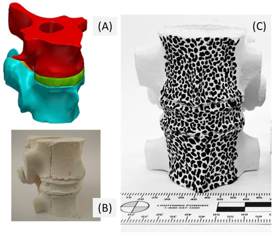
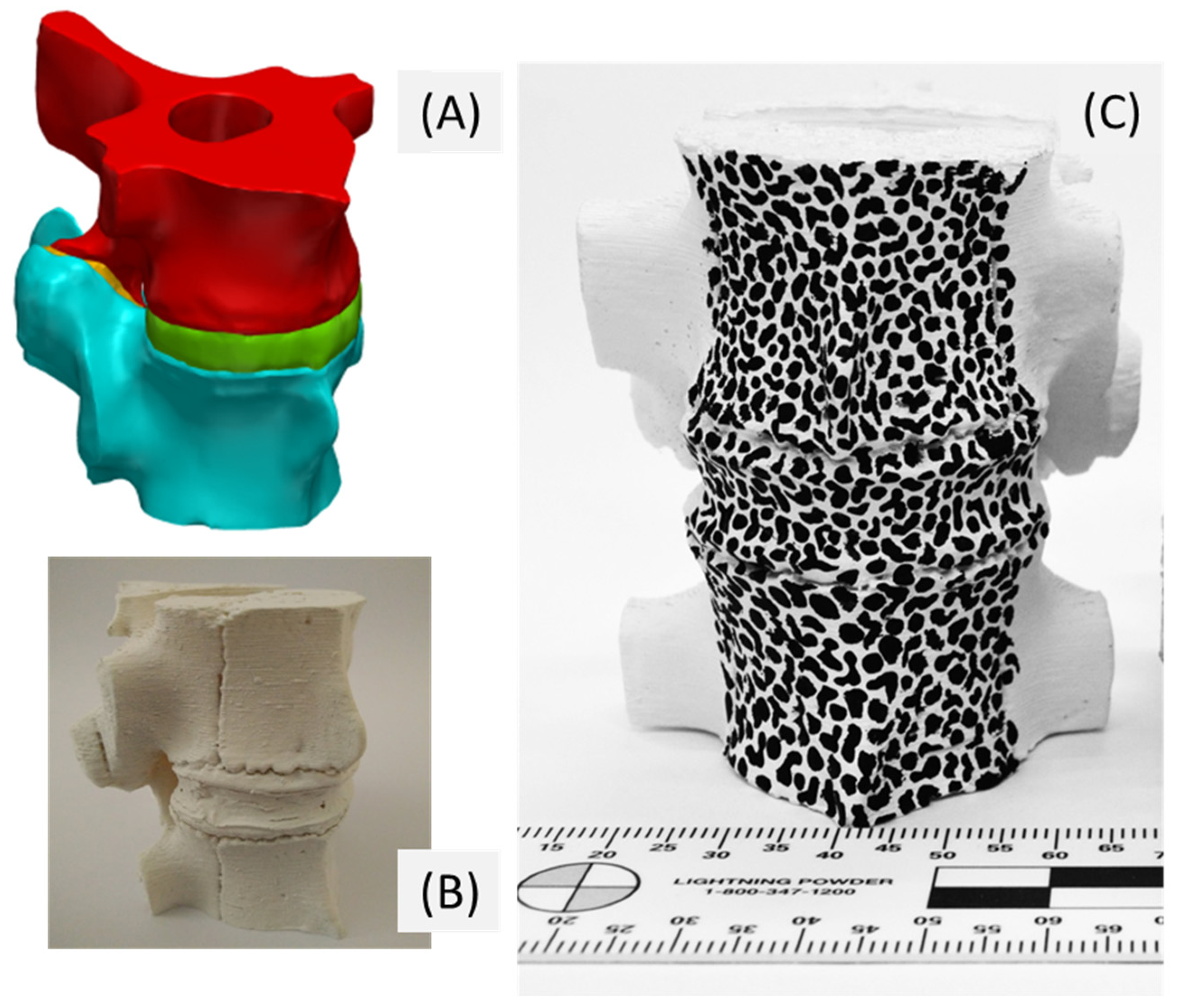
All samples (whole vertebral bodies and cores) were printed using a fused deposition modelling (FDM) UPrintSE printer (Stratasys Inc., Eden Prairie, MN, USA), based on computer aided design (CAD) geometry samples at 100 μm, a scale that achieves mechanically accurate 3D-printed replicas of biological objects [15,20]. Tool paths for 3D printing were generated using CatalystEX v4.5 (Stratasys Inc., Eden Prairie, MN, USA). Production of whole AVB samples were based on micro-CT image stacks obtained from six porcine vertebral bodies. The entire vertebral body was sectioned, removing the endplates, vertebral arch and pedicles. The AMS analogue was based on RMS#4 (Real Motion Segment), one of these six spine specimens, and was created using the same method as the AVB samples, with one exception: IVD and facet joints were introduced that fused the top and bottom vertebral bodies. The IVD and intra-facet cartilage (area between facet joints) were formed from PT Flex 85 liquid rubber of Shore A hardness 85 (Polytek Development Corp., Easton, PA, USA). The two-part rubber was mixed and then injected into a cast built around the IVD superior and inferior endplates and the superior and inferior articular processes, using Sugru mouldable glue (FormFormForm Ltd., London, UK). Accurate IVD thickness (based on CT reconstructions) was ensured by placing struts that were equal in height to the IVD (also produced using PT Flex 85) at three points on the endplates. Figure 2 shows the completed sample following the injection of the IVD and facet ligaments, which has been reported in detail by Franceskides et al. [20,21].
Figure 2.
Artificial motion segment, as used and analysed in a previous study [19]; (A) surface model following CT scanning ready for use with AN; (B) 3D-printed sample as a physical model; (C) AM physical model with a surface speckle ink pattern to allow surface strain mapping by using DIC.
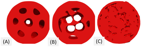
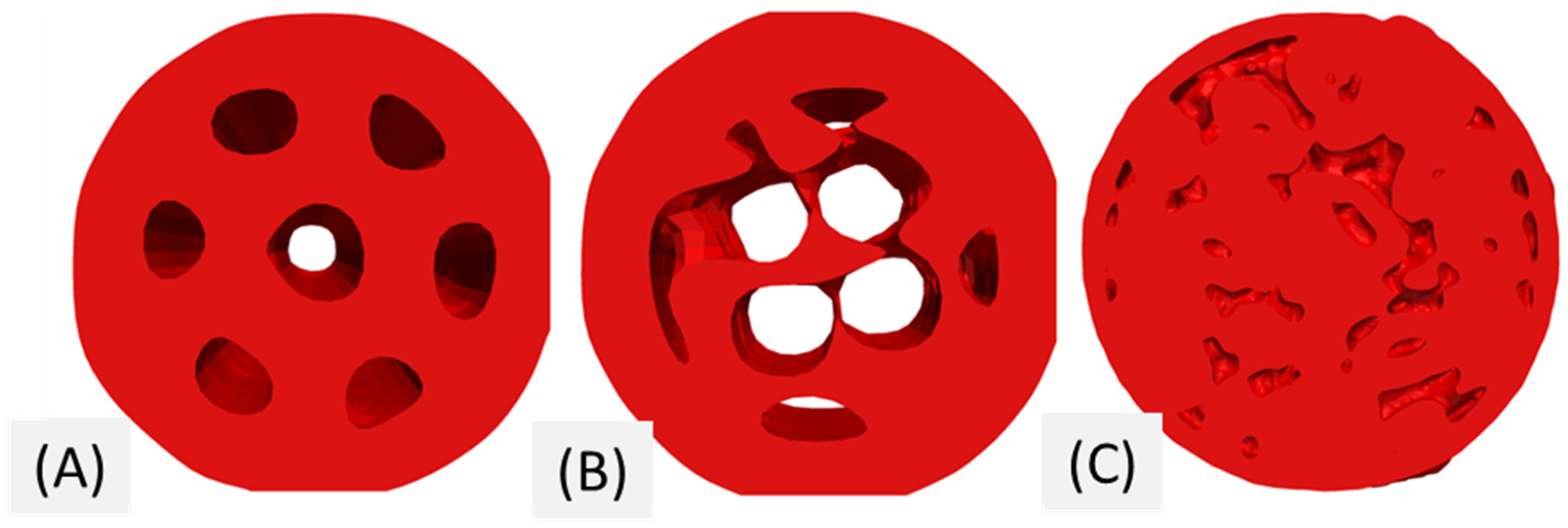
Core samples with longitudinal holes (Figure 3A) were created using SolidWorks 2018 SP1 (Dassault Systèmes SolidWorks Corporation, Vélizy-Villacoublay, France). For these samples, the diameter of the hole was kept constant at 2 mm, but the number of holes varied (0, 1, 3, 5 and 7).
Figure 3.
Examples of (A) longitudinal, (B) transverse and (C) artificial vertebral cores.
The transverse cores with varying fill distribution (Figure 3B) were created by modelling a solid cylinder and using CatalysEX to select three different default fills: solid, high density or low density. Using these settings, the external structure was printed as a solid, whereas the density of the internal structure was varied by controlling the amount of fill, achieving a more even density variation throughout the cylinder (particularly in the x and y planes) compared to the longitudinal cores. Both the longitudinal and transverse cores were 9 mm in diameter and 25 mm long to maintain comparability between the test results. The data from the longitudinal and transverse cores were pooled (LTCs) for broader density variation and to improve the population size in comparison to the AVCs.
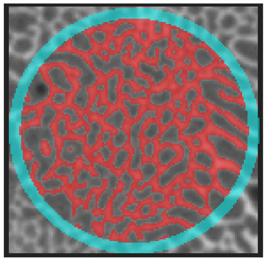
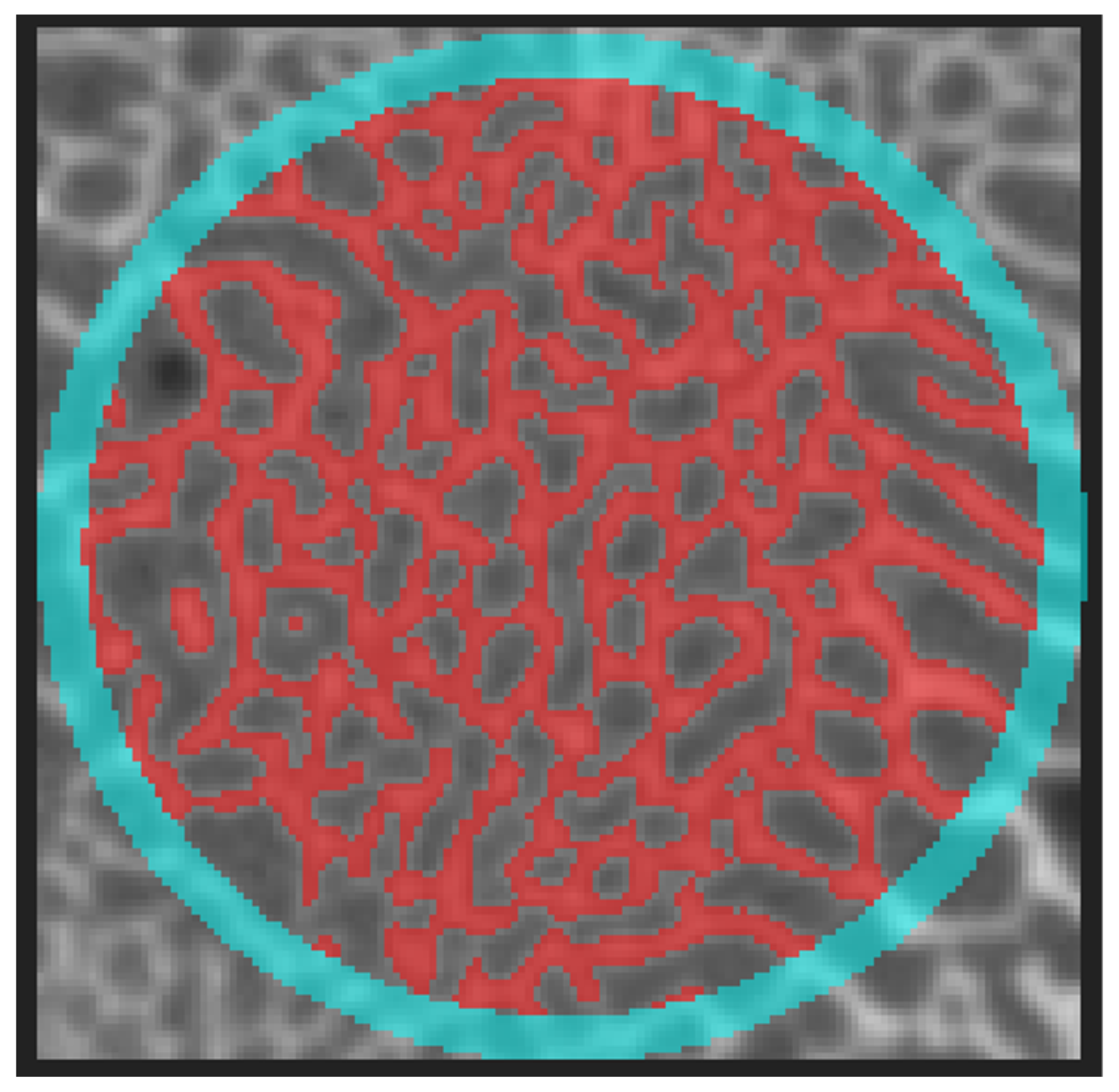
The AVCs were generated by segmenting micro-CT scans from two cadaveric porcine motion segments (real motion segments, named RMS#4 and RMS#5) obtained in our previous studies [19,20,21]. These were derived from two porcine vertebrae at levels L1-L2 and T12-L1, respectively (Figure 3C). The cores were taken from a cylindrical region of interest, 9 mm in diameter, and aligned with the axis of loading and axis of the spine. The lengths were limited by the size of the actual vertebrae (without the endplates), so that AVCs were shorter than the longitudinal and transverse cores (LTC). Core density was varied by controlling the amount of bone thresholded compared to the baseline. The thresholding level has a significant effect on the microarchitectural values produced for cellular solids, as has been shown recently [24]. Models with a threshold grey scale value of ±20 in relation to the baseline were generated in addition to the standard upper/lower peak thresholding procedure. Figure 4 shows an example of the segmentation. A thin solid shell of material was added to the circumferential edge of the cores (to create a solid surface around the core), as shown in blue, to prevent tool path generation errors, which are generated by the cellular discontinuous geometry of these cellular samples.
Figure 4.
Artificial vertebral core segmentation with an outer shell added circumferentially around the edge (The bright colours are only used for illustration of the segmentation).
The AVCs were bathed, prior to scanning, in a Support Cleaning Apparatus (PADT Inc., Tempe, AZ, USA). This ensured that all the internal support was removed without damaging or affecting the rest of the structure. Once all the support was removed, samples were scanned at the same resolution and settings as stated above for the longitudinal and transverse cores.
These were scanned using a CT H225 cone beam μCT scanner (Nikon Metrology UK Ltd., Tring, UK) operated at 80 kV and 65 μA. Noise reduction and beam hardening correction were achieved using CT Pro 3D (Nikon Metrology UK Ltd.). The geometric magnification produced a voxel dimension of 26 μm for all the cores, 55 μm for the AVBs and 89 μm for the AMS experiment. The data generated during the scans were used for finite element modelling and morphometric analysis. ImageJ v1.52 [25] with the BoneJ v1.4.3 [26] plugin was used to calculate the GS values of the ABS peak and air peak, as well as the volume fraction, degree of anisotropy and mean GS through the entire cylinder. Table 1 shows the volume fraction and weight of the LTC samples.
Table 1.
Volume fraction and weight of the longitudinal and transverse cores (LTCs).
Table 2 shows the allocation of cores from the original specimens, highlighting parameters such as the volume fraction, weight, volume and length.
Table 2.
Properties of artificial vertebral cores.
2.1. Mechanical Testing
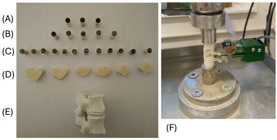
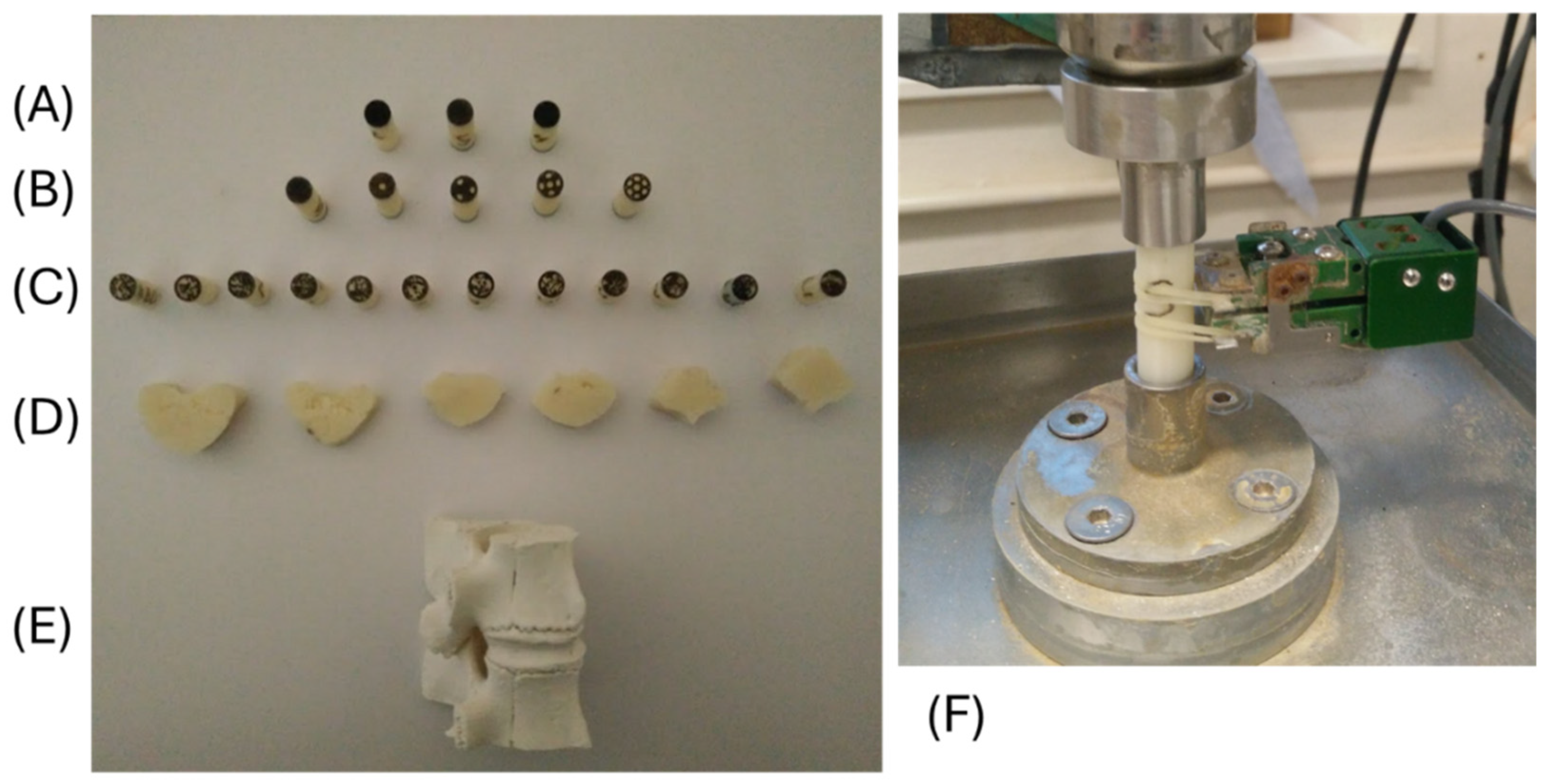
All analogues were tested under compression in a Dartec Series HC25 servo-hydraulic testing machine (ZwickRoell Ltd., Worcester, UK) with a 9610 controller running its own Workshop 96 software. The tests were conducted from rest to plastic failure (or force limit of the load cell, whichever came first) under crosshead displacement control at 0.01 mm/s. The forces were logged using a 5-kN load cell (Sensotec, RDP Electronics Ltd., Wolverhampton, UK). The core specimens were held centred in endcaps. The bottom endcap was fixed, whereas the top endcap featured a self-levelling platen (Figure 5F).
Figure 5.
Porcine spinal analogues. Starting from the topmost samples: (A) three transverse cores of different densities, produced by setting the printer to use infills of solid, low density and high density; (B) five longitudinal cores with varying number of holes (practically same in-fill setting but in effect variable apparent density, depending on the number of holes present: 0, 1, 3, 5, 7 from left to right); (C) twelve transverse cores produced by varying the threshold levels of the scans; (D) six vertebral bodies; and (E) a complete AM motion segment. (F) Mechanical testing setup of the cores with a contact extensometer attached and held in place against the central portion by rubber bands.
In the AMS experiment, the loading was delivered using a flat, spherical-joint, self-levelling platen at the top and a fixed, flat platen at the base, whereas the AVBs were fixed between an endcap, spherical-joint platen at the top and a fixed-endcap platen at the base.
2.2. Finite Element Model
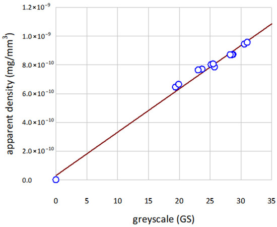
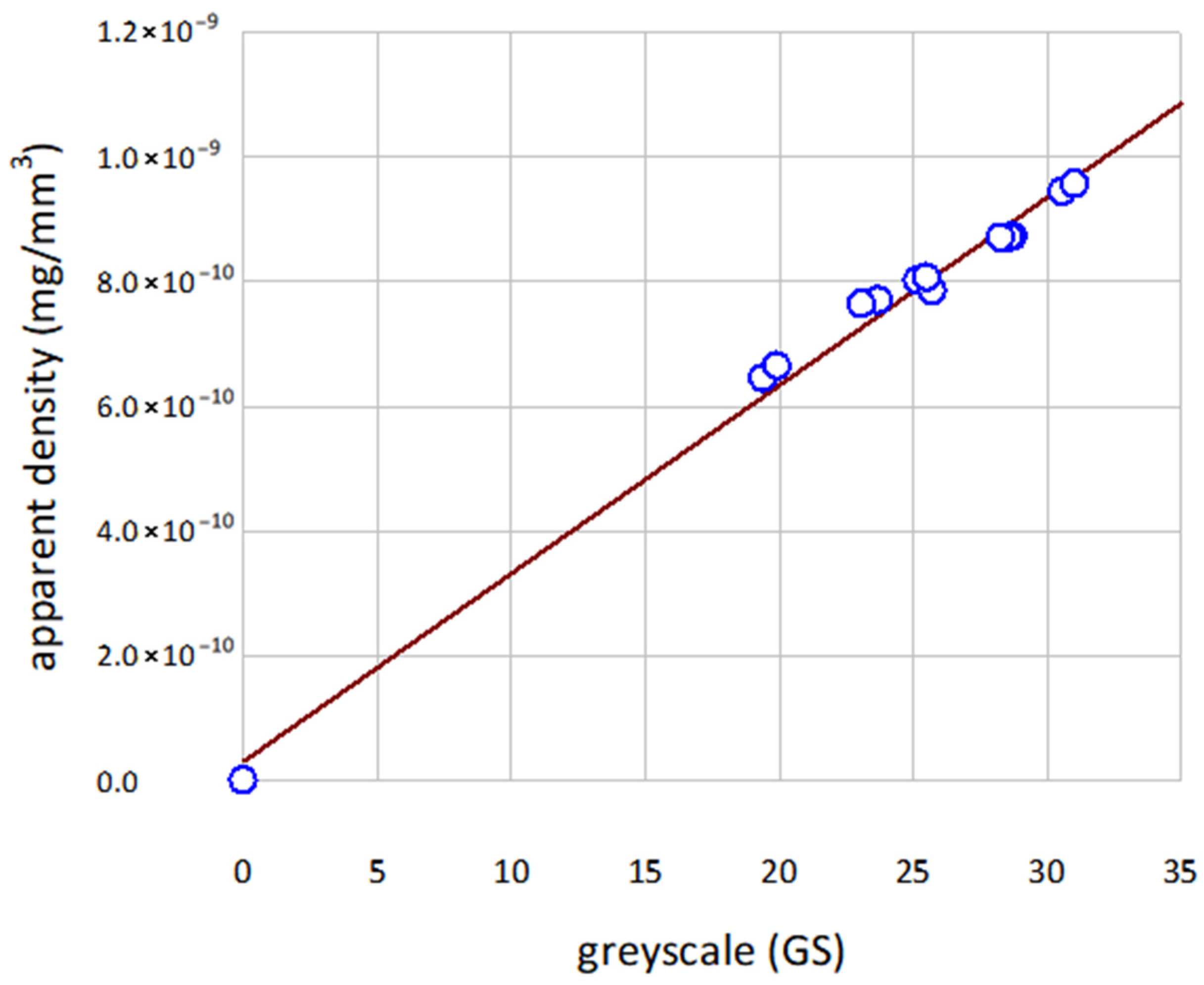
Geometry: The CT images were segmented using Simpleware ScanIP M-2017.06-SP2 (Synopsys Inc., Mountain View, CA, USA). CT scans were resampled to 100 μm for consistency between meshes. The outer surface of all samples was identified using standard thresholding techniques. The meshes were created using quadratic 10-node tetrahedral elements in the FE-Free meshing routine of Simpleware ScanIP. This was done at the coarsest setting (−50) to reduce the computational cost of the models as much as possible, allowing for analysis on the less capable machines that are often found in a clinical environment. The average GS air peak and the measured apparent density (mass/volume) [27] were used to draw a linear relationship between the GS and apparent density (Figure 6).
Figure 6.
Artificial core apparent density plotted against grey scale (GS). Model curve (red line) App Dens = 3.082 × 10⁻¹¹ GS + 1.31 × 10⁻¹¹ (Table 3).
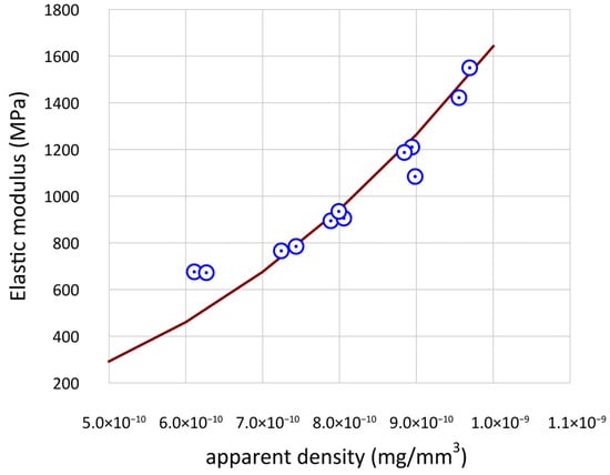
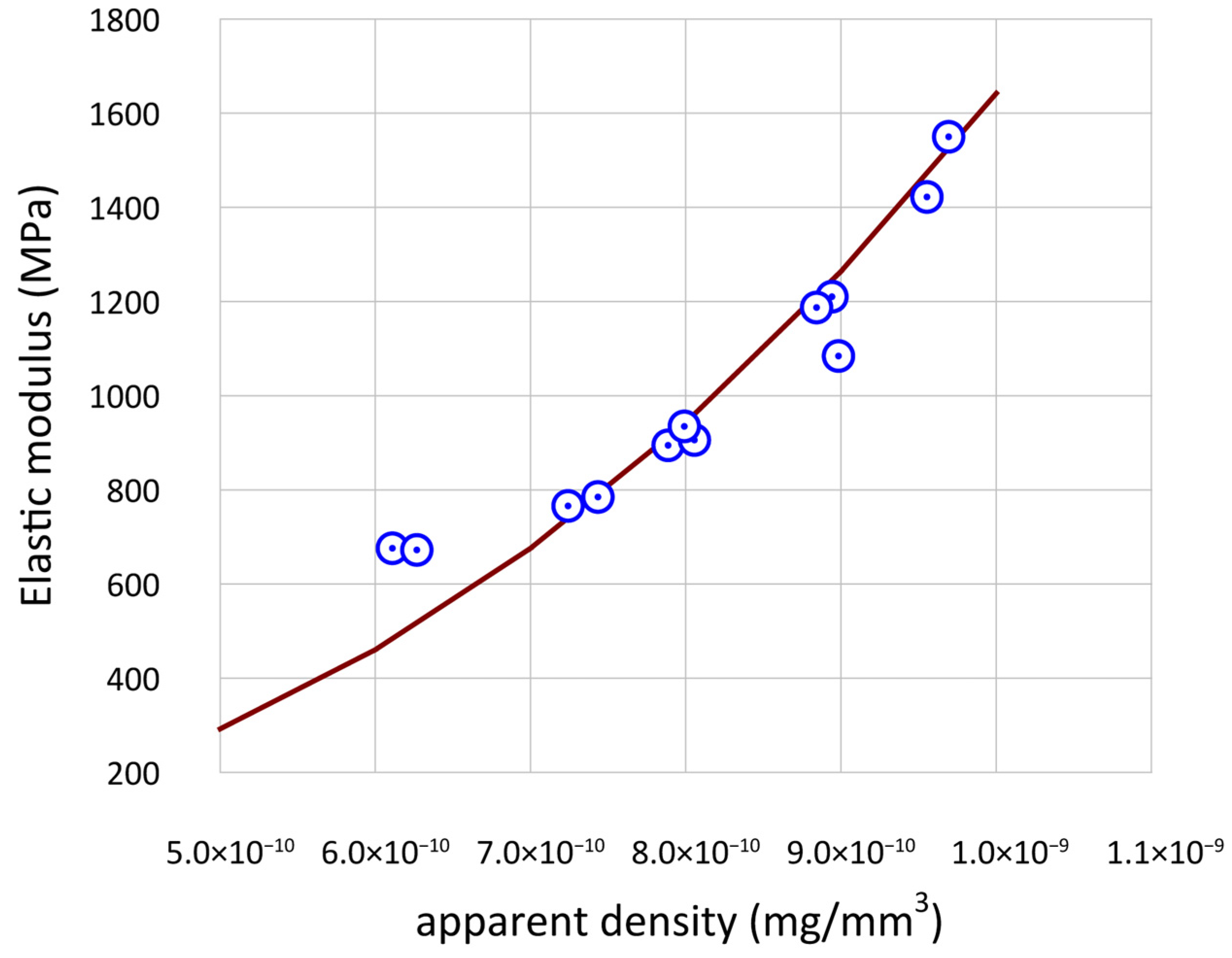
The relationship between density and elastic modulus was described using a fitted power law curve (Figure 7) that was similar to that reported for trabecular bone samples [28].
Figure 7.
Artificial core elastic modulus plotted against apparent density. Model curve (red line) E = 4.135 × 1025 ρ2.489 (Table 3).
This was done twice: once for the LTC and again for the AVC samples. A Poisson’s ratio of 0.35 [29,30] was applied to complete the linear elastic model for the bone analogues. The AMS included an additional analogue two-part rubber IVD, which was modelled as a human intervertebral disc with an elastic modulus of 2.5 MPa and a Poisson’s ratio of 0.49. This value is representative of the entire composite body, comprising the nucleus pulposus and annulus fibrosus: the two ground substance inner and outer components of the IVD [31]. Two FE material models were created, one (FLC) based on the 3DP samples with the geometry of idealised longitudinal cores (computer designed cancellous inner architecture) and another (F-DLS) on the AVCs (scanned real cancellous architecture). Their relationships and material properties are compared in Table 3.
Table 3.
ANSYS mechanical properties of idealised and artificial vertebral cores (AVCs). ABS: Acrylonitrile butadiene styrene and IVD: intervertebral disc.
The models generated for all cores (LTCs and AVCs) comprised ~15,000 elements and were analysed using ANSYS APDL v15.0 (ANSYS Inc., Canonsburg, PA, USA) with an implicit solver. The top face was coupled to replicate the effects of a platen and displaced by 1 mm, whereas the bottom face of each specimen was fixed in all directions. The nodal reaction forces on the top face were computed to provide a stiffness measurement for validation against the mechanical testing.
3. Results
Accurate patient-specific finite element models and their analogues are needed in the fields of forensic and injury biomechanics, as well as orthopaedics. Micro-CT data were used to develop analogue models of porcine spinal motion segments with subsequent FEA models. These were then tested in a similar manner to compare their stiffness and reaction forces. Clinical CT scanning is currently conducted at 300–500 μm [32], which is a much lower resolution than the image segmentation used for the FEA in this study (100 μm). The present scans produced a more accurate FEA model because there was more data upon which to base the model. The discrepancy between the in vivo and in vitro CT scanning resolution could be a limiting factor for the clinical application of this model.
3.1. Artificial Cores
The arithmetic mean and standard deviations for the morphological results of the samples are shown in Table 4.
Table 4.
Comparison of morphometric data for artificial vertebral cores (AVCs) and longitudinal and transverse cores (LTCs), with asterisks (*) indicating significant differences.
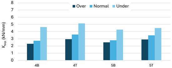
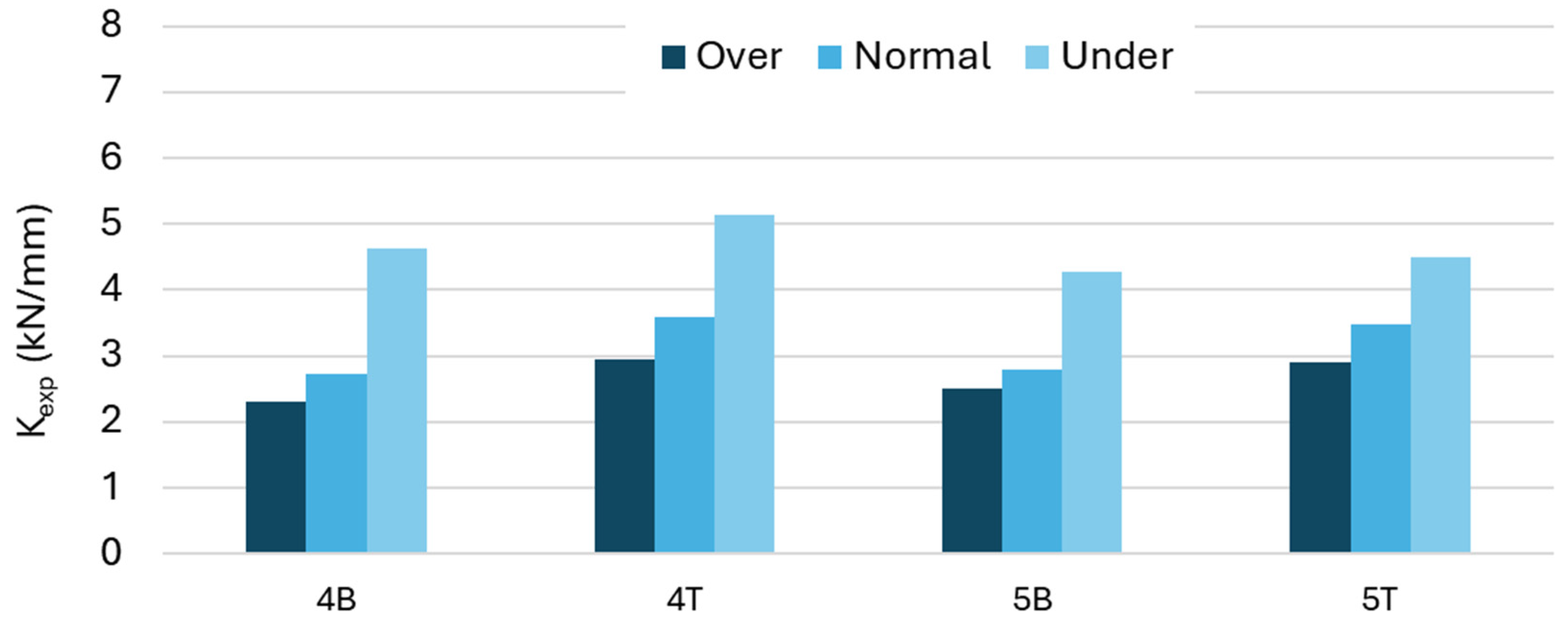
To compare the morphometry with that of porcine trabecular bone, the four AVCs were thresholded using the standard method (4BN, 4TN, 5BN, 5TN) and then subsampled into AVC Sub; two-sample t-tests were used to calculate significant differences in relation to LTCs (p = 0.05). The AVC and AVC Sub samples featured virtually indistinguishable means; therefore, in this context, they can be used interchangeably. The length was consistent for the LTCs, but there was greater variation in the AVC and AVC Sub samples. The volume fraction was 8% higher on average for the LTCs, but showed greater variance than AVC and AVC Sub. The apparent density of the two models was similar and showed an inter-specimen correlation when normalised against the volume fraction (6.76 × 10⁻¹⁰ LTC, 6.21 × 10⁻¹⁰ AVC). The LTC dataset was mostly orthotropic, whereas the AVC dataset showed a much more anisotropic construction (0.305). Figure 8 shows the variance in the experimental stiffness values for the different vertebral bodies and its dependence on the thresholding method, revealing a nonlinear relationship between the −20 and +20 GS.
Figure 8.
Experimentally obtained stiffness (Kexp) values for the 3 different thresholds on 4 samples. When the threshold value increased (less material in the 3DP sample), the material stiffness decreased by 15.3% on average (average DK = −0.48 kN/mm; significant paired t-test p = 0.009 < 0.05). For a similar shift in the threshold to the lower value (added more material in the 3DP sample) and the stiffness increased on average by 47.3% (average DK = +1.49 kN/mm; significant paired t-test p = 0.004 < 0.05), showing that the thresholding level had a significant and non-linear effect on the properties of the produced 3DP sample.
The morphometric data shown in Table 4 reveal several trends. The AVC and AVC Sub data have similar arithmetic means, but the AVC Sub data have a much smaller standard deviation. This is expected, because the population has been reduced from 12 to four but is segmented in the same manner, reducing the morphological variance. It also shows that different thresholding methods have a linear effect on morphological measurements. This is in contrast to the nonlinear mechanical relationship between the thresholding techniques (Figure 8).
The apparent density is controlled by the threshold value applied during segmentation. Our model shows a nonlinear relationship between the apparent density and experimental elastic modulus, which is reflected in the power exponent in the fitted material model (ρapp2.489, R2 = 0.944), which is in the range of previously reported bone FEA models (ρapp1.49–ρapp3) [12].
The degree of anisotropy for the LTCs was close to 1 ± 0.016 (mean ± SD), which is understandable, as these are computer-designed and have directionality. Meanwhile, the AVCs had anisotropy of 0.305 ± 0.0925, which was similar to previously reported porcine vertebral anisotropy values of 0.321 ± 0.067 [33]. There was no significant difference in apparent density between the LTC and AVC samples (two-sample t-test, p = 0.754) and when normalised against the volume fraction, the mean values were much closer (6.76 × 10⁻¹⁰ LTC, 6.21 × 10⁻¹⁰ AVC), showing that there is little variance in the 3D-printing procedure, which could affect the mechanical results. Furthermore, no significant differences in volume fraction were observed between the cores. Therefore, both sets had a similar spread of volume fractions, indicating that other morphological properties affect the mechanical response and model characteristics.
Bone has a higher elastic modulus than ABS, 10–20 GPa vs. 3 GPa, respectively, so a greater volume of ABS material (higher BV/TV inevitably) is needed to achieve a mechanically comparable behaviour at the macrostructural level [19]. As previously recommended [34], we measured the bone volume divided by the total volume (BV/TV) of porcine vertebrae in the range 0.30–0.40, whereas the cores used in this study were 0.80 ± 0.12 overall and the AVBs were 0.82 ± 0.98. Given the lower elastic modulus of ABS, higher BV/TV values are necessary in bone analogues and are therefore adjusted so that the models achieve a similar stiffness upon loading [19].
The in silico and experimental stiffness results for the longitudinal and transverse cores showed good agreement. We obtained two computational stiffness values: one using model F-DLS and the other using model FLC (Table 5).
Table 5.
Longitudinal and transverse core stiffness results. K: Stiffness. Exp: Experimental value. FEA: Finite element analysis value. F-DLS and FLC are FE models.
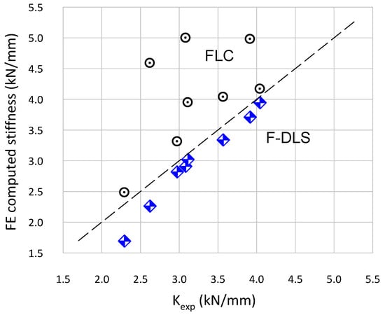
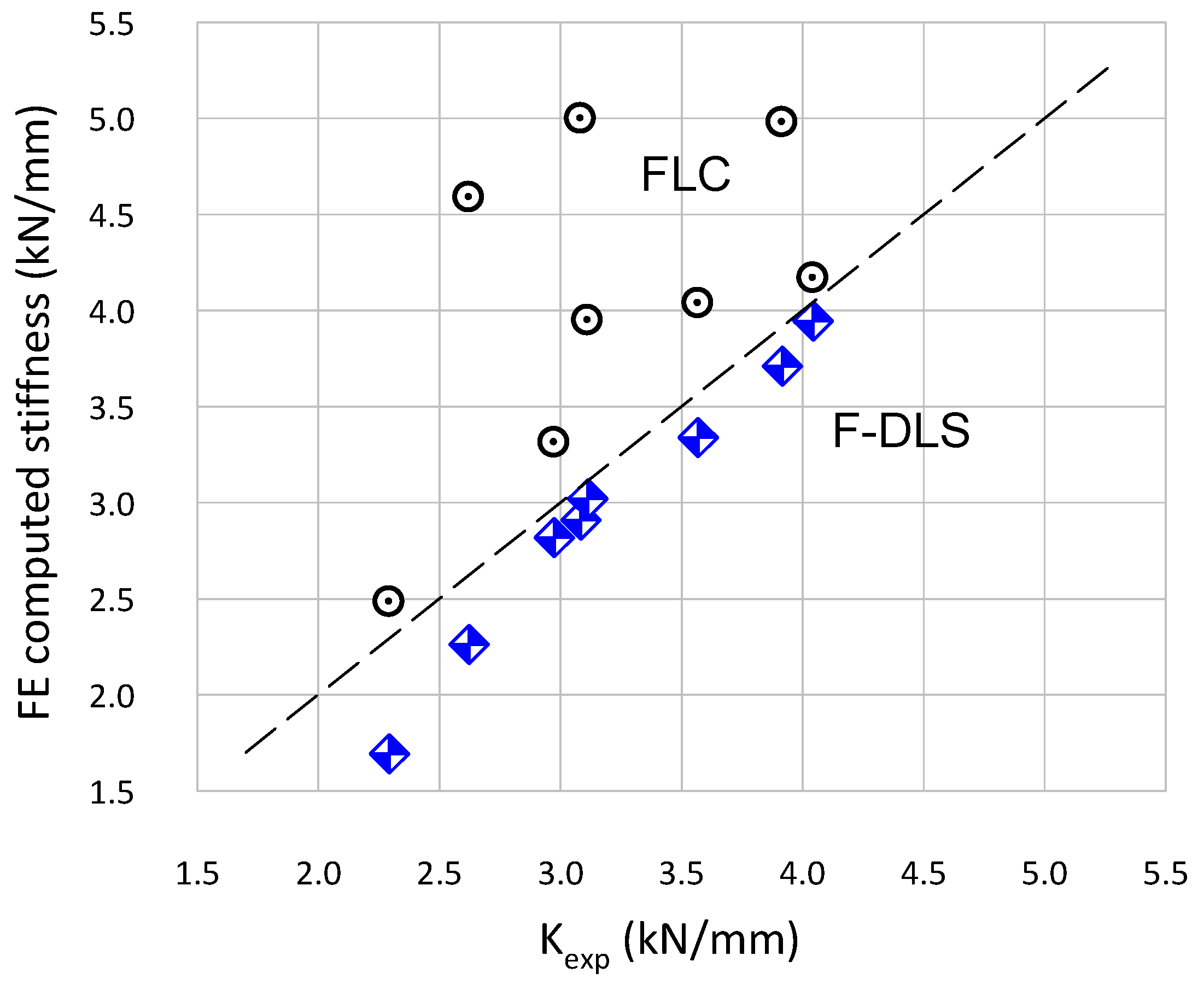
Model F-DLS under-predicted stiffness by 10.5% on average (average DK = −0.24 kN/mm; significant paired t-test p = 0.005 < 0.05), whereas model FLC over-predicted the stiffness by 26.1% on average (average DK = +1.10 kN/mm; Significant paired t-test p = 0.004 < 0.05). Figure 9 compares the computed stiffness values of the two FE material models against the experimental values for the longitudinal cores; the more significant qualitative result is that the behaviour of the FLC models was erratic, while the F-DLS models followed the experimental data linearly and proportionately.
Figure 9.
FE model stiffness values for FLC (circles) and F-DLS (diamonds) models vs. experimentally determined stiffness (Kexp). The line of equality is also shown (dashed).
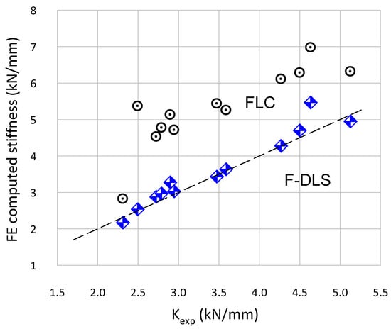
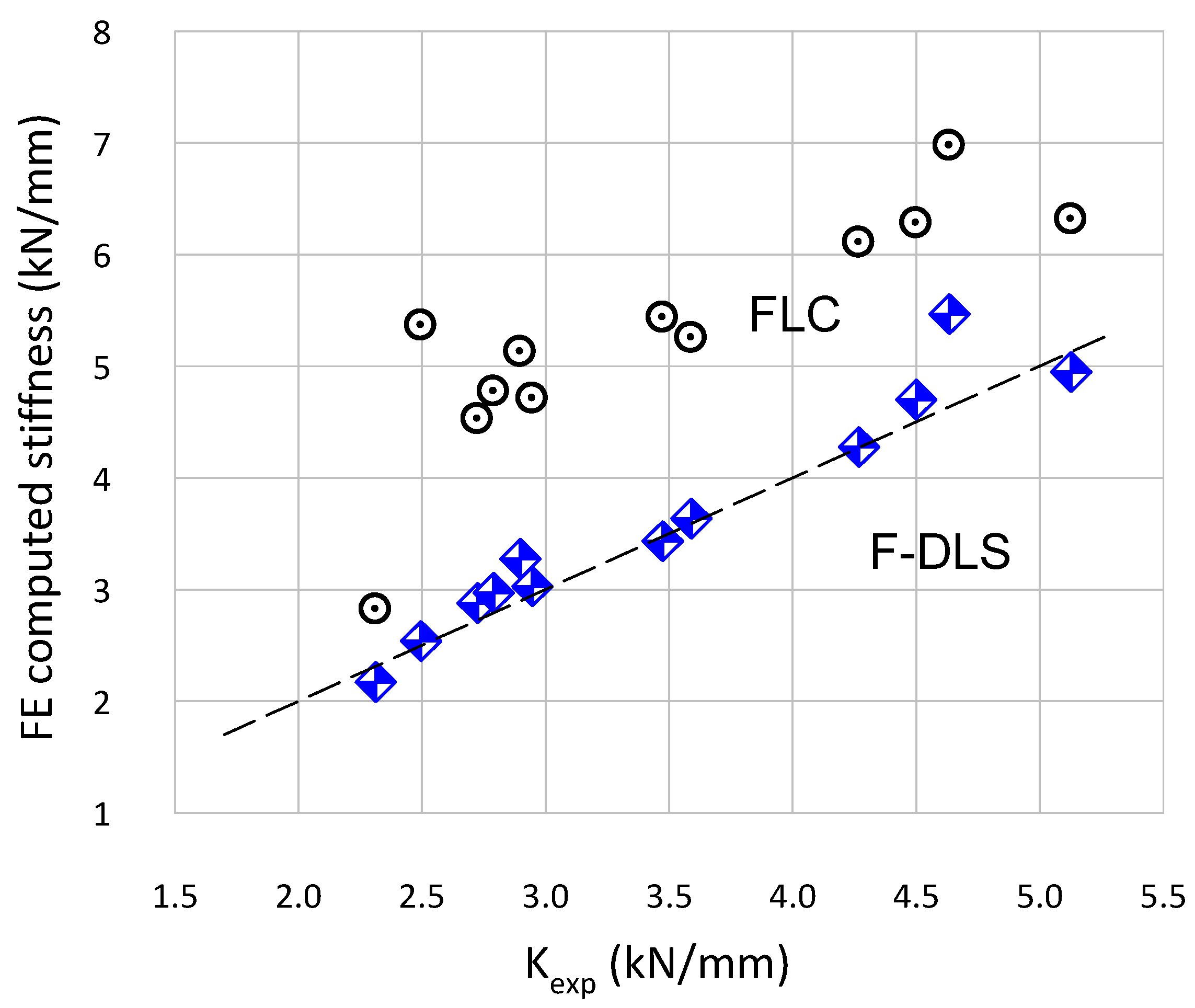
Table 6 summarises the stiffness results for AVCs and shows a 3.6367–371 average under-prediction of stiffness (average DK = −0.13 kN/mm; not significant paired t-test p = 0.121 > 0.05) when comparing the F-DLS material model to the experimental data. By contrast, the FLC models over predicted the stiffness values by 55.8% on average (average DK = +1.83 kN/mm; significant paired t-test p = 0.001 < 0.05). Like previously, while the F-DLS models followed the experimental data linearly, the FLC models were erratic (presenting noise). Figure 10 compares the computed stiffness of the two material models against the experimental values for the cores created using RMS#4 and RMS#5.
Table 6.
Artificial vertebral core stiffness results. BV/TV: Bone volume divided by the total volume. K: Stiffness. Exp: Experimental value. FEA: Finite element analysis value. F-DLS and FLC are material models.
Figure 10.
AVC4 and AVC5 core F-DLS (diamonds) and FLC (circles) material models. FEA-derived stiffness (KFEA) plotted against experimentally determined stiffness (KExp). The line of equality is also shown (dashed).
3.2. Artificial Vertebral Bodies
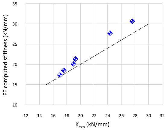
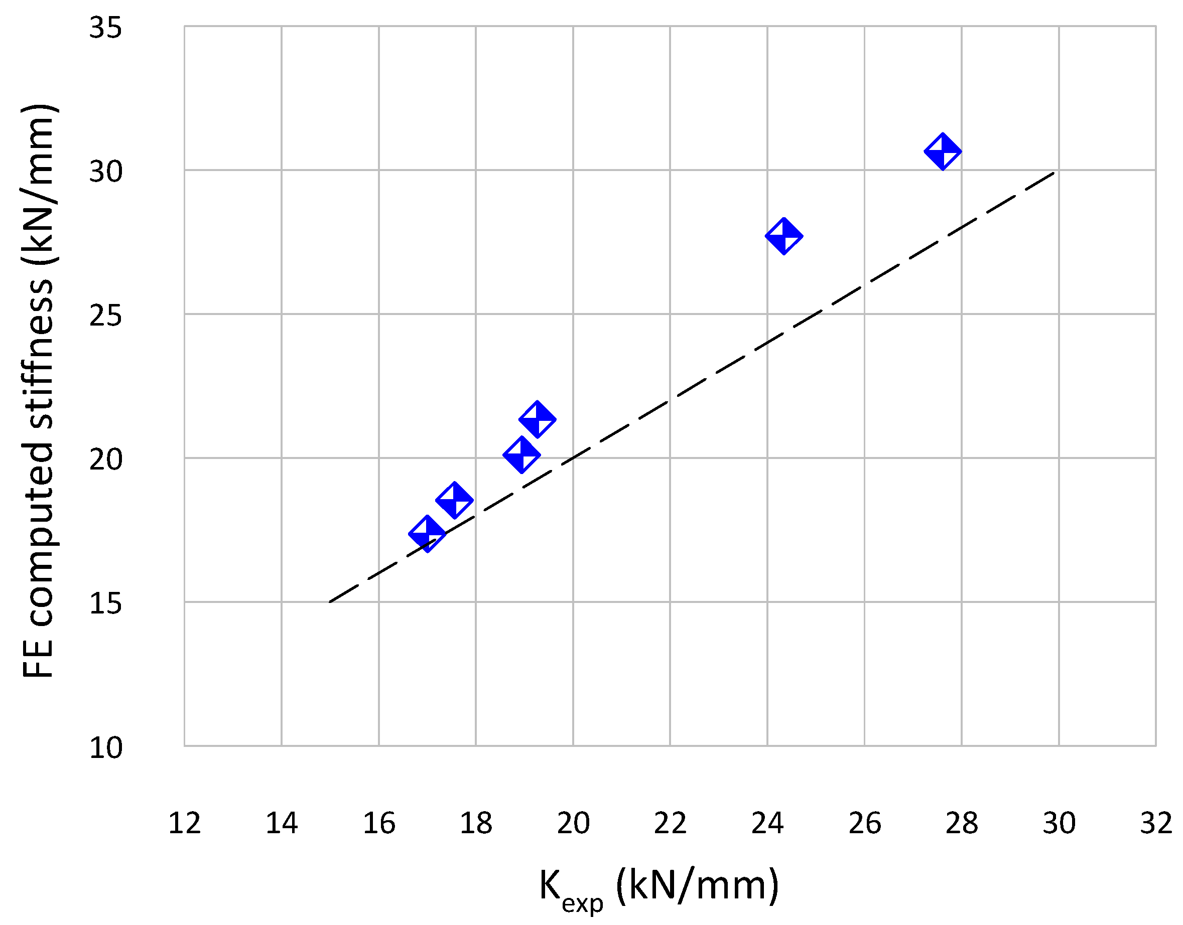
Table 7 and Figure 11 shows morphometric and mechanical testing data from the AVBs, using the F-DLS material model. This repeats the previous analysis, now at a higher level (vertebrae are larger and more intricate in geometry than simple cores) by focusing on the use of the more successful F-DLS model. The FE models consistently over-predicted the stiffness of whole vertebral body samples by 7.5% on average (average DK = +1.83 kN/mm; not significant paired t-test p = 0.014 < 0.05), but followed the experimental data with fidelity and in a linear manner.
Table 7.
Artificial vertebral body morphometric data and experimental results. BV/TV: Bone volume divided by the total volume. K: Stiffness. Exp: Experimental value. F-DLS is a material model.
Figure 11.
Behaviour of AVB data (artificial vertebral bodies): FEA-derived stiffness K(F-DLS) vs. experimentally determined stiffness Kexp. The line of equality is also shown (dashed).
3.3. Artificial Motion Segments
The F-DLS material model agreed well with the experimental dataset, providing confidence at this stage to progress the analysis to the next higher level, which is the artificial motion segment (AMS). AMS comprises two vertebrae and the intervertebral disc (IVD) between them. No further tests were conducted with the FLC model, due to its relative inaccuracy compared to the F-DLS model. At this point, we concentrate on the actual force/displacement curve produced in tests and in silico.
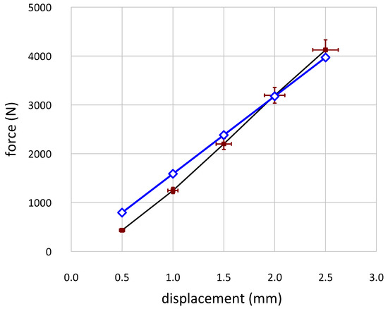
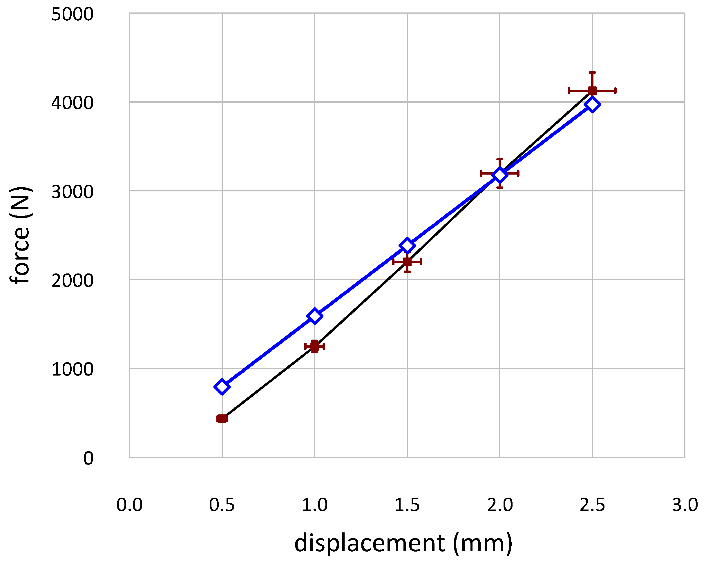
The reaction forces recorded for the AMS analogue are compared to the corresponding FEA model tested using the F-DLC material model in Figure 12. An AMS comprises two 3DP vertebrae of ABS and a rubberlike artificial IVD. The non-linear properties of the IVD part of the manufactured physical model only allow for the coincidence of test results and model predictions over a range of displacements, which can only be tuned by the researcher within a range, as shown here for displacements above 1.3 mm. We cannot elaborate any further on the suitability of the two-part liquid polyurethane rubber system (PT Flex 85, Polytek, Easton, PA, USA) we used here, for producing a more biofidelic intervertebral disc. The solution we used was tuned for the right Shore hardness for the physical model and a modulus of 2.5 MPa for the in silico one. Of course, there are other physical properties and the very linearity of the curve that must be accurately matched to the IVD material. This is beyond the scope of this paper. It is very likely that with the new technological advancements in 3D printers, which can inject a variety of softer polymers, an artificial IVD can be produced that possesses more biofidelic properties and a composite hierarchical organisation and microstructure.
Figure 12.
Behaviour of the AMS data: comparison of experimental (red) and computational force/displacement data (blue). (Experimental error bars were on average ±5% for load and 8% for displacement) The computational and experimental results agreed closely (NS difference) for displacements of 1.3 mm and above. The experimental data contain the non-linear nature of the artificial IVD material and other real-world phenomena, such as contact effects with the platens where there are asperities, and these show as an increase in stiffness as the load increases. The computational data of course has no such end contact effects, as all loading scenarios are idealised in silico.
The IVD properties played a greater role in determining the overall stiffness response of the motion segment than expected, both for cadaveric and analogue samples, as suggested in earlier reports [35]. This is because vertebral bodies are orders of magnitude stiffer than the IVDs and associated soft-tissue ligaments, leading the IVDs to deform more readily and fail earlier under compressive loading than the vertebral bodies. This highlights a greater need for accurate IVD and soft tissue replication in analogues and the models based on them. When generating the AMS finite element model, the IVD and facet ligaments were created using the faded disc boundary, which may have overestimated or underestimated the motion segment stiffness, depending on how the soft tissue was reconstructed, leading to the differences in observed stiffness.
Overall, the results of this study indicate that with a careful, staged and multiscale approach where one gradually increases the degree of complexity, good agreement between the physical and in silico model can be achieved. This promises to deliver both physical and in silico models which mimic real musculoskeletal structures well, and this offers a range of opportunities for scientists, practitioners and manufacturers in terms of implant design and applications.
4. Discussion
The present paper works around the research hypothesis that a multiscale modelling approach, which integrates high-resolution imaging data (such as CT/MRI), optimised thresholding techniques, and additive manufacturing, can produce biofidelic physical and computational models of skeletal structures (e.g., porcine vertebrae) that accurately replicate both morphological and mechanical properties, enabling reliable use in clinical and biomechanical applications [1,2,3,4,5,6]. The outcomes of this approach can be used in pre-surgical planning and simulation; biomechanical testing for research; medical education, allowing for hands-on approach methods [3,4,5]; medicolegal reconstruction (forensic biomechanics cases [7,8]) and the design and development of implants and surgical tools [2,3,5].
The present paper describes a clinical problem that is centred around the challenges of accurately replicating human (or animal) anatomical structures and biomechanical behaviour, using both computational (FEA) and physical (AM) models for clinical and research purposes. The challenges arise from the inherent limitations of both these two methodologies (FEA and AM) in imaging resolution, modelling complexity and material fidelity. More specifically, our study reinforced and added to the well-known challenges which mainly have to do with (i) computational models (in silico) that are too complex and/or idealised; (ii) real world biological variability and mechanical behaviours that are hard to replicate; (iii) imaging quality (CT/MRI resolution and thresholding) which can significantly influence model accuracy; and (iv) soft tissue modelling, especially for the complex spinal components we examined here, which are limited by material and manufacturing constraints [2,6,10,13,23,35].
In applying our two-modalities (FEA/AM) methodology on a spine section as an example, we reaffirmed that biological tissues are hierarchically complex and the attempts of modelling them (physically and computationally) are challenging at multiple length scales [15,16,19,20,21]. For spine segments, in particular, we saw that the intervertebral discs (IVDs) are difficult to model, which is consistent with known gaps in spinal biomechanics research. We could also clearly see that the well-known trade-off between radiation dosage and CT imaging resolution is a problem which is here now and must be addressed in the future. However, the arrival of new high-resolution in vivo scanners (achieving 300 micron in vivo) allow for the same scan data to be used for both FEA modelling and 3DP. A recent paper from our lab demonstrated the production of FEA models from such modern clinical scanners and the computational fidelity that can be expected in such applications [36]. In carrying out the present study, it was clear to us that there are existing gaps and challenges in the literature and acquired biomechanical knowledge due to the lack of standard frameworks for validation, verification, and sensitivity analysis (a recuring problem in biomechanical modelling research), and in particular, there are challenges in accurate soft tissue segmentation and reproduction, which is known to influence biomechanical simulation accuracy [11,12,13,14].
The present paper examined the behaviour of the spine motion segment in a hierarchical approach. The 3DP samples were produced, tested, and modelled at the material sample level (cores) at the vertebral body level, IVD level and at the analogue motion segment level. Validation took place first on the components and was then scaled up to a motion segment that combines all. Only one complete motion segment was modelled, and that may be seen as a limitation, but the subcomponents were created after scanning a larger number of vertebral samples as examples and testing multiple of the lower scale level components. The rationale was to establish the biofidelic accuracy of the 3DP process up and down the length scales, because the complexity exists in the subcomponents and their modelling, rather than in the testing of a whole analogue motion segment. We believe that the trade-off paid off, as the final complete AMS behaved very similarly to the in silico model. This was only possible through fine-tuning the lower length scale parts.
The creation of physical models of natural tissue structures by 3D printing and their computational equivalents are fraught with challenges at each length scale, because natural structures are hierarchically built and architecturally very complex. We have shown that it is possible to produce biofidelic spine motion segments in both analogue and digital (in silico) forms. There is still some distance to cover with regard to modelling spinal motion segments, particularly the intervertebral discs. There are two important aspects in producing physical analogues, the material level properties (IVD is an example in question) and the length scale issues in scanning and 3D printing. The scanning equipment in this study uses a higher resolution than the current clinical CT scans, and to achieve this resolution in practice would require the exposure of patients to higher levels of radiation than is currently advisable. There is promising new research into CT dose reduction, which theoretically allows for the retrieval of much higher spatial resolutions in vivo without harm to patients [37]. The lack of a clear framework for validation, verification and sensitivity analysis [38] makes the case for a real need for further studies into the definition of accurate replicas in conjunction with FEA models and in paying particular attention to the segmentation of soft tissues in the spine, because this has shown to have a substantial effect on the biomechanical response of the analogues.
The creation of an accurate analogue means that tests involving many different procedures and devices will become more compatible and feasible due to the lack of intra-specimen variability and biohazard risks, thus making rapid prototyping ultimately an attractive alternative for in vitro spine biomechanical testing. Moreover, in cases where the biomechanical response of the spine is of paramount importance, the synthetic spine and its associated methods presented here have been shown to exhibit a reliable force/displacement response in compression loading at least. At this point, it must be mentioned that a further limitation of the present application was that the finer dimension of the trabecular elements of the artificial vertebral bodies were cruder (thicker) than the actual scanned trabeculae. This was a manufacturing limitation, in this instance, resulting in higher BV/TV ~0.8 values to the scanned bone samples in order to achieve the same loading response. In this respect, the current model remains a geometric approximation, rather than a functional biological analogue, necessitating further experimental validation and design to address bone-like physiological structures and loading conditions.
5. Conclusions
In conclusion, our present study has shown that it is practically feasible to produce near-biofidelic spine motion segments in two forms (modelling and physical), offering a more holistic approach for future work in the field. This fact advocates for greater use of synthetic models as a valid alternative for in vitro testing, because they offer standardisation, reproducibility and safety (no biohazard risks). For the design and production of bespoke and patient specific implants [39], the study supports the notion that rapid prototyping can be used to produce analogues for testing medical devices and surgical procedures, thus reducing the need for cadaveric and animal models. On clinical translation, it offers an example of a pathway which can integrate technologies such as computing and clinical scanning [2,5,6,23], which, with advances in radiation dose reduction and increasing resolution, will offer new avenues for applications.
Author Contributions
Conceptualisation: C.F. and P.Z.; Data curation: C.F. and T.S.; Formal analysis: C.F., T.S. and M.C.G.; Funding acquisition: C.F. and P.Z.; Investigation: C.F. and T.S.; Methodology: C.F.; Project administration: P.Z.; Resources: C.F.; Software: C.F., T.S. and M.C.G.; Supervision: P.Z.; Validation: C.F. and T.S.; Visualisation: C.F., T.S. and M.C.G.; Writing (original draft): C.F.; Writing (review and editing): C.F., T.S., M.C.G. and P.Z. All authors have read and agreed to the published version of the manuscript.
Funding
The authors disclosed receipt of the following financial support for the research, authorship, and/or publication of this article from a CDS Cranfield University internal funding to C.F. and T.S. and funding to P.Z. from RCDM (Royal College for Defence Medicine), Birmingham (grant no. DMSRSG20130905).
Institutional Review Board Statement
Ethical approval was granted by the Cranfield University Research and Ethics committee (CURES/2539/2017, Bone mechanobiology research studies group: spine strength assessment). Animal tissue from the food chain was used for the scans. No human tissue or data was used at any stage of this work.
Data Availability Statement
Data for this manuscript will be made available through the Cranfield University CORD data depository and preservation system (https://cranfield.figshare.com, accessed on 30 November 2025).
Acknowledgments
The main bulk of the material of this paper originates from the PhD Thesis of the first author (Chapter 6), which is listed in the Reference [19]. This paper is dedicated to one of the authors, Mike Gibson, whose untimely death was a great loss to us all.
Conflicts of Interest
The authors declare that the research was conducted in the absence of any commercial or financial relationships that could be construed as a potential conflict of interest.
Declaration AI
The authors categorically declare that AI has not been used anywhere in this work, either in conceptualisation, in carrying out the work, or in reporting.
Abbreviations
The following abbreviations are used in this manuscript:
| 3DP | 3D printing |
| ABS | acrylonitrile butadiene styrene |
| AM | additive manufacturing |
| AMS | analogue motion segment |
| AVC | artificial vertebral cores |
| AVB | artificial vertebral body |
| BV/TV | bone volume/tissue volume |
| DA | degree of anisotropy |
| FDM | fused deposition modelling |
| IVD | intervertebral disc |
| LTC | cores with longitudinal and transverse pores artificially designed |
| FLC | FE model cores of idealised/artificially designed porosity architecture |
| F-DLS | FE model cores with internal trabecular architecture from scans |
References
- Agarwal, R.; Malhotra, S.; Gupta, V.; Jain, V. The application of Three-dimensional printing on foot fractures and deformities: A mini-review. Ann. 3D Print. Med. 2022, 5, 100046. [Google Scholar] [CrossRef] [Scilit]
- Ventola, C.L. Medical Applications for 3D Printing: Current and Projected Uses. Pharm. Ther. 2014, 39, 704–711. [Google Scholar] [PubMed]
- Burgade, R.; Uhl, J.F.; Delmas, V.; Dubois de Mont-Marin, G.; Rosset, P.; Le-Nail, L.R. Use of 3D printing as a simulation tool for trauma surgery of the pelvis. Ann. 3D Print. Med. 2021, 3, 100025. [Google Scholar] [CrossRef] [Scilit]
- Biglino, G.; Capelli, C.; Wray, J.; Schievano, S.; Leaver, L.K.; Khambadkone, S.; Giardini, A.; Derrick, G.; Jones, A.; Taylor, A.M. 3D-manufactured patient-specific models of congenital heart defects for communication in clinical practice: Feasibility and acceptability. BMJ Open 2015, 5, e007165. [Google Scholar] [CrossRef] [Scilit] [PubMed]
- Famaey, N.; Vander Sloten, J. Soft tissue modelling for applications in virtual surgery and surgical robotics. Comput. Methods Biomech. Biomed. Eng. 2008, 11, 351–366. [Google Scholar] [CrossRef] [Scilit]
- Żukowska, M.; Rad, M.A.; Górski, F. Additive Manufacturing of 3D Anatomical Models-Review of Processes, Materials and Applications. Materials 2023, 16, 880. [Google Scholar] [CrossRef] [Scilit] [PubMed]
- Jani, G.; Johnson, A.; Marques, J.; Franco, A. Three-dimensional(3D) printing in forensic science–An emerging technology in India. Ann. 3D Print. Med. 2021, 1, 100006. [Google Scholar] [CrossRef] [Scilit]
- Biggs, M. 3D Printing Applied to Forensic Investigations. In Essentials of Autopsy Practice; Rutty, G., Ed.; Springer: Cham, Switzerland, 2019. [Google Scholar] [CrossRef] [Scilit]
- Grassi, L.; Väänänen, S.P.; Yavari, S.A.; Weinans, H.; Jurvelin, J.S.; Zadpoor, A.A.; Isaksson, H. Experimental validation of finite element model for proximal composite femur using optical measurements. J. Mech. Behav. Biomed. Mater. 2013, 21, 86–94. [Google Scholar] [CrossRef] [Scilit] [PubMed]
- McDonald, K.; Little, J.; Pearcy, M.; Adam, C. Development of a multi-scale finite element model of the osteoporotic lumbar vertebral body for the investigation of apparent level vertebra mechanics and micro-level trabecular mechanics. Med. Eng. Phys. 2010, 32, 653–661. [Google Scholar] [CrossRef] [Scilit]
- Dall’Ara, E.; Karl, C.; Mazza, G.; Franzoso, G.; Vena, P.; Pretterklieber, M.; Pahr, D.; Zysset, P. Tissue properties of the human vertebral body sub-structures evaluated by means of microindentation. J. Mech. Behav. Biomed. Mater. 2013, 25, 23–32. [Google Scholar] [CrossRef] [Scilit] [PubMed]
- Helgason, B.; Gilchrist, S.; Ariza, O.; Vogt, P.; Enns-Bray, W.; Widmer, R.P.; Fitze, T.; Pálsson, H.; Pauchard, Y.; Guy, P.; et al. The influence of the modulus-density relationship and the material mapping method on the simulated mechanical response of the proximal femur in side-ways fall loading configuration. Med. Eng. Phys. 2016, 38, 679–689. [Google Scholar] [CrossRef] [Scilit]
- Lee, C.-H.; Landham, P.R.; Eastell, R.; Adams, M.A.; Dolan, P.; Yang, L. Development and validation of a subject-specific finite element model of the functional spinal unit to predict vertebral strength. Proc. Inst. Mech. Eng. Part H J. Eng. Med. 2017, 231, 821–830. [Google Scholar] [CrossRef] [Scilit]
- Viceconti, M.; Hunter, P. The Virtual Physiological Human: Ten Years After. Annu. Rev. Biomed. Eng. 2016, 18, 103–123. [Google Scholar] [CrossRef] [Scilit] [PubMed]
- Franceskides, C.; Leger, T.; Horsfall, I.; Tozzi, G.; Gibson, M.; Zioupos, P. Evaluation of bone excision effects on a human skull model—I: Mechanical testing and digital image correlation. Proc. Inst. Mech. Eng. Part H J. Eng. Med. 2020, 234, 337–345. [Google Scholar] [CrossRef] [Scilit]
- Franceskides, C.; Gibson, M.; Zioupos, P. Evaluation of bone excision effects on a human skull model—II: Finite element analysis. Proc. Inst. Mech. Eng. Part H J. Eng. Med. 2020, 234, 346–355. [Google Scholar] [CrossRef] [Scilit]
- Barr, J.R.; Wang, T.; Pelletire, M.H.; Walsh, W.R. Initial Experience with Synthetic Spinal Motion Segments: Biomechanical. In Proceedings of the 60th Ann Meet Orthopaedic Research Society, New Orleans, LA, USA, 15–18 March 2014. [Google Scholar]
- Campbell, J.; Imsdahl, S.; Ching, R. Evaluation of a synthetic L2-L5 spine model for biomechanical testing. In Proceedings of the 56th Ann Meet ORS, Orthopaedic Research Society, New Orleans, LA, USA, 6–9 March 2010. [Google Scholar]
- Franceskides, C. Subject-Specific Spinal Functional Model of Hard and Soft Tissues. Ph.D. Thesis, Cranfield University, Shrivenham, UK, 2018. Available online: https://dspace.lib.cranfield.ac.uk/server/api/core/bitstreams/4002324f-9f18-4012-b0ff-e785f15067bf/content (accessed on 30 November 2025).
- Franceskides, C.; Arnold, E.; Horsfall, I.; Tozzi, G.; Gibson, M.C.; Zioupos, P. Spinal motion segments—I: Concept for a subject-specific analogue model. J. Bionic Eng. 2020, 17, 747–756. [Google Scholar] [CrossRef] [Scilit]
- Franceskides, C.; Arnold, E.; Horsfall, I.; Tozzi, G.; Gibson, M.C.; Zioupos, P. Spinal motion segments—II: Tuning and optimisation for biofidelic performance. J. Bionic Eng. 2020, 17, 757–766. [Google Scholar] [CrossRef] [Scilit]
- Hambli, R. Micro-CT finite element model and experimental validation of trabecular bone damage and fracture. Bone 2013, 56, 363–374. [Google Scholar] [CrossRef] [Scilit] [PubMed]
- Buie, H.R.; Campbell, G.M.; Klinck, R.J.; MacNeil, J.A.; Boyd, S.K. Automatic segmentation of cortical and trabecular compartments based on a dual threshold technique for in vivo micro-CT bone analysis. Bone 2007, 41, 505–515. [Google Scholar] [CrossRef] [Scilit] [PubMed]
- Adams, G.J.; Cook, R.B.; Hutchinson, J.R.; Zioupos, P. Microarchitecture and morphology of bone tissue over a wide range of BV/TV assessed by micro-computed tomography and three different threshold backgrounds. Med. Eng. Phys. 2022, 106, 103828. [Google Scholar] [CrossRef] [Scilit]
- Schneider, C.; Rasband, W.; Eliceiri, K. NIH Image to ImageJ: 25 years of image analysis. Nat. Methods 2012, 9, 671–675. [Google Scholar] [CrossRef] [Scilit] [PubMed]
- Doube, M.; Kłosowski, M.M.; Arganda-Carreras, I.; Cordelières, F.P.; Dougherty, R.P.; Jackson, J.S.; Schmid, B.; Hutchinson, J.R.; Shefelbine, S.J. BoneJ: Free and extensible bone image analysis in ImageJ. Bone 2010, 47, 1076–1079. [Google Scholar] [CrossRef] [Scilit]
- Adams, G.J. Quality Factors at the Material and Structural Level That Affect the Toughness of Human Cancellous Bone. Ph.D. Thesis, Cranfield University, Shrivenham, UK, 2017. Available online: http://dspace.lib.cranfield.ac.uk/handle/1826/15952 (accessed on 30 November 2025).
- Keaveny, T.M.; Hayes, W.C. A 20-year perspective on the mechanical properties of trabecular bone. J. Biomech. Eng. 1993, 115, 534–542. [Google Scholar] [CrossRef] [Scilit] [PubMed]
- Rodríguez, J.F.; Thomas, J.P.; Renaud, J.E. Mechanical behavior of acrylonitrile butadiene styrene (ABS) fused deposition materials. Experimental investigation. Rapid Prototyp. 2001, 7, 148–158. [Google Scholar] [CrossRef] [Scilit]
- Dreischarf, M.; Zander, T.; Shirazi-Adl, A.; Puttlitz, C.M.; Adam, C.J.; Chen, C.S.; Goel, V.K.; Kiapour, A.; Kim, Y.H.; Labus, K.M.; et al. Comparison of eight published static finite element models of the intact lumbar spine: Predictive power of models improves when combined together. J. Biomech. 2014, 47, 1757–1766. [Google Scholar] [CrossRef] [Scilit]
- Kuo, C.S.; Hu, H.T.; Lin, R.M.; Huang, K.H.Y.; Lin, P.C.; Zhong, Z.C.; Hseih, M.L. Biomechanical analysis of the lumbar spine on facet joint force and intradiscal pressure—A finite element study. BMC Musculoskelet. Disord. 2010, 11, 151–163. [Google Scholar] [CrossRef] [Scilit]
- Burghardt, A.J.; Link, T.M.; Majumdar, S. High-resolution computed tomography for clinical imaging of bone microarchitecture. Clin. Orthop. Relat. Res. 2011, 469, 2179–2193. [Google Scholar] [CrossRef] [Scilit] [PubMed]
- Zapata-Cornelio, F.Y.; Day, G.A.; Coe, R.H.; Sikora, S.N.F.; Wijayathunga, V.N.; Tarsuslugil, S.M.; Mengoni, M.; Wilcox, R.K. Methodology to Produce Specimen-Specific Models of Vertebrae: Application to Different Species. Ann. Biomed. Eng. 2017, 45, 2451–2460. [Google Scholar] [CrossRef] [Scilit]
- Laffosse, J.M.; Odent, T.; Accadbled, F.; Cachon, T.; Kinkpe, C.; Viguier, E.; Sales de Gauzy, J.; Swider, P. Micro-computed tomography evaluation of vertebral end-plate trabecular bone changes in a porcine asymmetric vertebral tether. J. Orthop. Res. Off. Publ. Orthop. Res. Soc. 2010, 28, 232–240. [Google Scholar] [CrossRef] [Scilit]
- Zander, T.; Dreischarf, M.; Timm, A.K.; Baumann, W.W.; Schmidt, H. Impact of material and morphological parameters on the mechanical response of the lumbar spine—A finite element sensitivity study. J. Biomech. 2017, 28, 185–190. [Google Scholar] [CrossRef] [Scilit]
- Cai, Y.; Zioupos, P.; Márquez-Grant, N.; Budair, B.; Junaid, S. Producing micro-finite element models from real-time clinical CT scanners: Calibration, validation and material mapping strategies. Front. Bioeng. Biotechnol. 2025, 13, 1670428. [Google Scholar] [CrossRef] [Scilit]
- Kitchen, M.J.; Buckley, G.A.; Gureyev, T.E.; Wallace, M.J.; Andres-Thio, N.; Uesugi, K.; Yagi, N.; Hooper, S.B. CT dose reduction factors in the thousands using X-ray phase contrast. Nat. Sci. Rep. 2017, 7, 15953. [Google Scholar] [CrossRef] [Scilit] [PubMed]
- Jones, A.C.; Wilcox, R.K. Finite element analysis of the spine: Towards a framework of verification, validation and sensitivity analysis. Med. Eng. Phys. 2008, 30, 1287–1304. [Google Scholar] [CrossRef] [Scilit] [PubMed]
- Zhang, G.Q.; Li, J.X.; Li, J.; Zhou, X.Y.; Xie, J.J.; Wang, A.M. Selective Laser Melting Molding of Individualized Femur Implant: Design, Process, Optimization. J. Bionic Eng. 2021, 18, 128–137. [Google Scholar] [CrossRef] [Scilit]

Disclaimer/Publisher’s Note: The statements, opinions and data contained in all publications are solely those of the individual author(s) and contributor(s) and not of MDPI and/or the editor(s). MDPI and/or the editor(s) disclaim responsibility for any injury to people or property resulting from any ideas, methods, instructions or products referred to in the content. |
© 2026 by the authors. Licensee MDPI, Basel, Switzerland. This article is an open access article distributed under the terms and conditions of the Creative Commons Attribution (CC BY) license.