


Abstract
The surface integrity of γ-TiAl alloys is critical for the performance and reliability of aerospace components due to their limited ductility and inherent brittleness. Although wire electrical discharge machining (W-EDM), milling and heat treatments are commonly employed during the manufacture of γ-TiAl parts, their combined influence on surface integrity remains insufficiently understood. This study investigates the effects of finishing operations and post-machining heat treatments on a Ti-48Al-2Cr-2Nb alloy produced by vacuum arc remelting (VAR). Specimens were sectioned by W-EDM and subsequently finished by dry milling. Surface integrity was evaluated through metallographic observations, microhardness measurements, and residual stress analysis, while annealing treatments between 700 and 1100 °C for 2 h were applied to assess the recovery of machining-induced alterations. W-EDM generated a cracked surface layer, revealing a significant limitation of this process for γ-TiAl components. Milling removed the damaged layer and produced a defect-free surface, however, it induced a plastically deformed subsurface region about 50 μm thick, accompanied by increased hardness and residual stresses. Annealing at 700 °C provided only partial recovery, whereas treatments at 900 °C and above promoted complete recrystallization of the affected layer, restoring hardness to values close to those of the bulk material. The results demonstrate that milling followed by annealing at 900 °C for 2 h effectively restores surface integrity without altering the bulk microstructure.
1. Introduction
Gamma titanium aluminides (γ-TiAl) have emerged as a class of advanced intermetallic alloys capable of combining low density with excellent specific mechanical properties and high-temperature strength. These characteristics have promoted their progressive incorporation into aerospace engine components, where weight reduction and thermal efficiency are key design requirements. The increasing industrial adoption of γ-TiAl alloys has been supported by significant developments in alloy design, processing technologies, and large-scale manufacturing routes, enabling their transition from laboratory materials to commercially viable engineering solutions [1,2].
Among the different γ-TiAl compositions, Ti-48Al-2Cr-2Nb has received considerable attention due to its attractive combination of oxidation resistance, creep performance, and high-temperature mechanical properties. The addition of chromium and niobium contributes to phase stability and environmental resistance while preserving the low-density characteristic of titanium aluminides. Consequently, this alloy has become one of the most extensively investigated γ-TiAl grades for aerospace applications and a representative material for assessing the influence of manufacturing processes on microstructural integrity and performance [2,3].
The properties of Ti-48Al-2Cr-2Nb are strongly dependent on its microstructural condition. Variations in phase constitution, colony morphology, grain size, and lamellar spacing can significantly alter the balance between strength, ductility, fracture toughness, and creep resistance. Depending on the solidification path and subsequent thermal history, the alloy may develop fully lamellar, nearly lamellar, duplex, or near-γ microstructures, each exhibiting distinct mechanical behavior. Consequently, microstructural control has become a key aspect in the design and optimization of γ-TiAl components [4,5].
Despite the remarkable advances achieved in alloy development, the machining of γ-TiAl alloys continues to present significant challenges due to their limited room-temperature ductility, low thermal conductivity and relatively high strength. These characteristics frequently lead to elevated cutting temperatures, severe tool wear and difficulties in controlling surface integrity. Earlier investigations established the basis for understanding the machining behavior of γ-TiAl alloys, while more recent studies have continued to highlight the strong influence of cutting conditions, tool geometry and material response on machining performance [6,7,8,9].
Among the available manufacturing routes for titanium aluminide components, wire electrical discharge machining (W-EDM) has gained considerable attention as a near-net-shape process capable of generating complex geometries in difficult-to-machine materials. The absence of mechanical cutting forces and the capability to manufacture intricate features make W-EDM particularly attractive for aerospace applications. Nevertheless, the localized thermal cycles associated with the process can generate recast layers, heat-affected zones, microcracks and surface modifications that may influence the performance of subsequent finishing operations [10]. Recent investigations have further shown that W-EDM-induced thermal damage can promote significant microstructural alterations and deterioration of mechanical properties, emphasizing the need for subsequent finishing strategies capable of restoring surface integrity and removing thermally affected material [11].
For this reason, finishing machining operations are generally required following W-EDM in order to achieve the dimensional accuracy and surface quality demanded by critical aerospace components. Surface integrity becomes a key issue at this stage because the interaction between cutting conditions and the underlying microstructure can modify subsurface deformation, microstructural features and residual stress generation. Surface integrity is particularly critical in γ-TiAl alloys because machining-induced defects, residual stresses and subsurface deformation may act as preferential sites for crack initiation and significantly affect fatigue performance and service reliability [12]. Previous investigations on γ-TiAl machining have reported surface alterations, microstructural modifications and tool wear mechanisms that are closely linked to the material microstructure and machining parameters [13,14].
Recent studies have further demonstrated that cooling and lubrication strategies significantly influence surface defects, work hardening, subsurface deformation and the overall surface integrity of γ-TiAl components [15,16]. Residual stresses constitute one of the most relevant indicators of surface integrity because they directly affect fatigue behavior, crack initiation, dimensional stability and service life. The generation of residual stresses during milling results from the combined effect of thermal and mechanical loads acting on the workpiece surface. Classical studies established the mechanisms responsible for residual stress formation during machining [17,18], whereas more recent investigations have shown that the final stress state is additionally influenced by the pre-existing residual stress field, material constitutive behavior and machining strategy [19,20,21,22]. Furthermore, compressive residual stresses generated during machining may retard crack propagation and improve the fatigue performance of γ-TiAl components, highlighting the importance of controlling the final stress state during manufacturing [12]. Therefore, understanding residual stress development is essential for establishing robust manufacturing routes for high-performance components.
Although significant efforts have been devoted to studying the metallurgy, manufacturing, and machinability of γ-TiAl alloys, limited attention has been paid to the influence of different heat-treatment-induced microstructures on the surface integrity generated during finishing operations performed after W-EDM. In particular, the combined effects of microstructural condition, recrystallization state and phase evolution on machining-induced residual stresses and subsurface alterations in Ti-48Al-2Cr-2Nb alloys remain insufficiently documented.
The significance and novelty of the present work lie in its integrated analysis of manufacturing-induced surface alterations and their subsequent evolution during heat treatment. The results demonstrate the relationship between machining-induced plastic deformation, hardness evolution, residual stress relaxation, recovery and recrystallization phenomena, contributing to a better understanding of the mechanisms governing the restoration and performance of γ-TiAl components manufactured for demanding engineering applications.
Therefore, the objective of the present work is to investigate the influence of different heat-treated microstructures of a cast Ti-48Al-2Cr-2Nb alloy on the surface integrity generated by finish milling after W-EDM processing. Special emphasis is placed on the characterization of residual stresses, phase constitution and microstructural modifications induced by machining, with the aim of establishing relationships between the initial microstructural state and the resulting surface integrity. Such understanding is expected to contribute to the optimization of manufacturing routes for titanium aluminide components intended for demanding aerospace applications.
2. Materials and Methods
2.1. Extraction of Samples by Wire EDM and Subsequent Machining Conditions
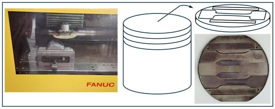
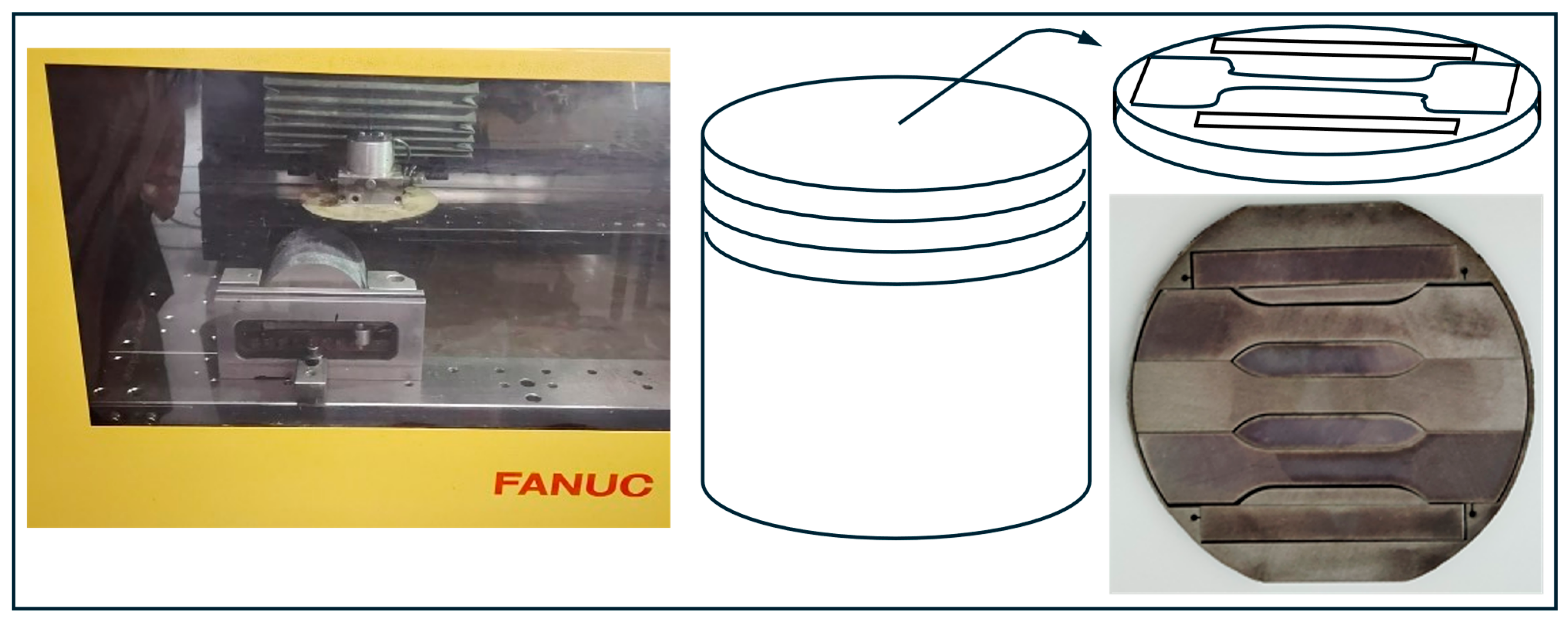
Cylindrical γ-TiAl bars with a diameter of 115 mm were sectioned into 4 mm-thick discs by wire electrical discharge machining (W-EDM) using a FANUC Oshino-mura, Japan wire-cut EDM system. Cutting was performed using the FANUC manufacturer’s recommended technological settings for titanium, employing a main cut followed by a single finishing pass. The cutting speed was approximately 0.49 mm/min, and a wire with a diameter of 0.2 mm was used. No additional trim-cut operations were applied. Once the discs were separated from the cylinder, different samples were obtained from each disc using the same methodology, as shown in Figure 1.
Figure 1.
Wire-EDM methodology for extracting test samples from cylindrical γ-TiAl bars.
In addition to the effects of VAR-casting and W-EDM conditions, the influence of two milling conditions on surface integrity was evaluated. Both machining conditions consisted of face milling at a feed rate, f, of 0.01 mm/rev, an axial depth of cut, p, of 0.2 mm, and two different cutting speeds of 50 and 100 m/min, respectively. In addition, the test at V = 50 m/min was performed under MQL lubrication, whereas milling at 100 m/min was carried out without lubrication, i.e., under dry conditions. These machining parameters were selected considering the range of technologically viable variables identified for end milling in previous studies [23,24]. These two conditions were chosen to represent the most favourable and least favourable machining scenarios within the scope of this study. It should be noted that both cutting speed and lubrication strategy vary simultaneously between the two machining conditions. Therefore, the present work does not aim to isolate the individual influence of each parameter, but rather to compare the material response under two representative machining scenarios selected from previous machining experience. Consequently, the observed differences are discussed in terms of the combined effect of the machining conditions. To carry out the milling operations, 390R-070204E-NL H13A inserts and an R390-012A12-07L tool holder with a diameter of 12 mm, both from Sandvik Coromant (Sandviken, Sweden), were selected.
2.2. Microhardness Tests
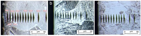
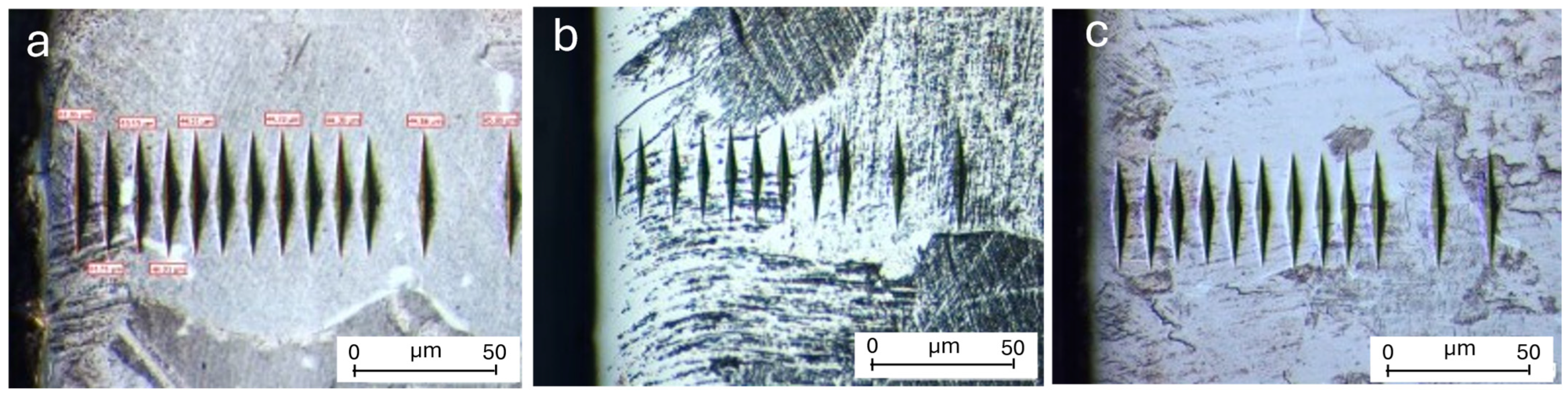
Microhardness tests were carried out using the Knoop 0.05 method on metallographic samples. The average of 12 readings was used to determine the hardness at the surface of the samples. For the subsurface, several measures were performed at different depths, as shown in Figure 2, to construct the hardness profile.
Figure 2.
Knoop microhardness (HK0.05) indentations on the subsurface of (a) the W-EDM cut sample; (b) the sample machined at f = 0.01 mmm/rev, p = 0.2 mm and v = 50 m/min under the MQL condition; (c) the sample machined at f = 0.01 mmm/rev, p = 0.2 mm and v = 100 m/min under the dry condition.
2.3. Heat Treatments
Heat treatments were carried out in a resistance furnace under a localized protective argon atmosphere. Argon was supplied directly to the specimen through a small, inverted cover placed over the sample. The specimens were heated to the target temperature, held for 2 h, and subsequently furnace cooled. This protective atmosphere was maintained throughout the entire thermal cycle, including both the heating and cooling stages.
2.4. Residual Stresses Measurements
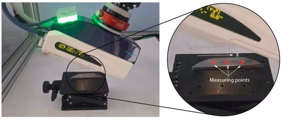
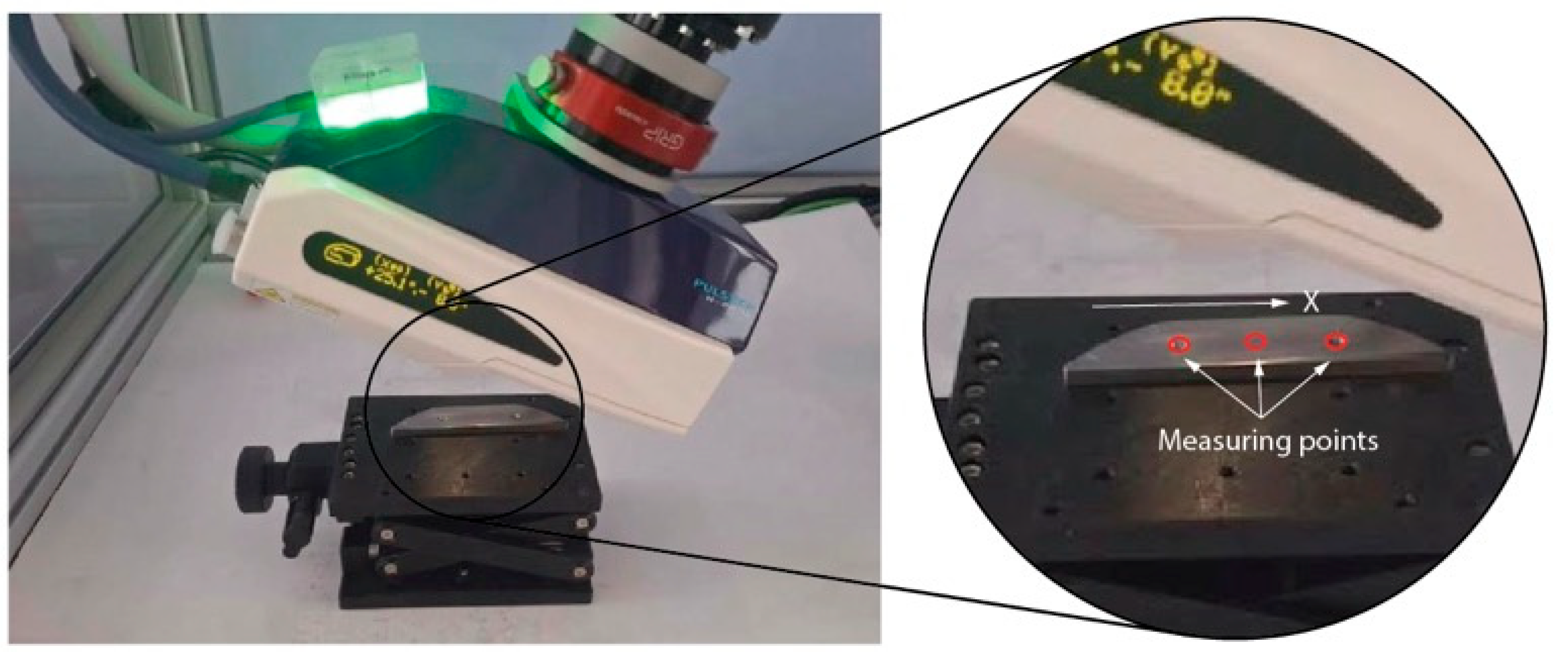
The residual stresses were evaluated on machined specimens by X-ray diffraction (XRD) and the hole-drilling method. The influence of face milling performed under different conditions, MQL at 50 m/min and dry at 100 m/min, was evaluated by means of X-ray diffraction (XRD) measurements using a PULSTEC µ-360s system (Pulstec Industrial Co., Ltd., Hamamatsu, Japan). The measurements were performed by employing a chromium X-ray tube and the Al (311) diffraction plane, with an incident angle of 25°. The instrument operates according to the cosα method, using a two-dimensional detector to acquire the complete Debye–Scherrer diffraction ring in a single exposure. Residual stresses were determined from the elastic lattice strains calculated from distortions of the diffraction ring according to Bragg’s law. The distance between the detector and the specimen surface was maintained at approximately 35.5 mm, as specified by the equipment setup. Three surface measurements were performed in different areas of each sample and the value obtained is expressed as the average (Figure 3). The orientation of the sample was established so that the X-direction coincided with the machining direction. The residual stresses determined by X-ray diffraction are representative of the near-surface region of the material, that is, the information depth is limited to only a few micrometres, typically within the first tens of micrometres below the surface [25].
Figure 3.
X-ray diffraction (XRD) measurements showing the three points measured on each sample.
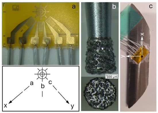
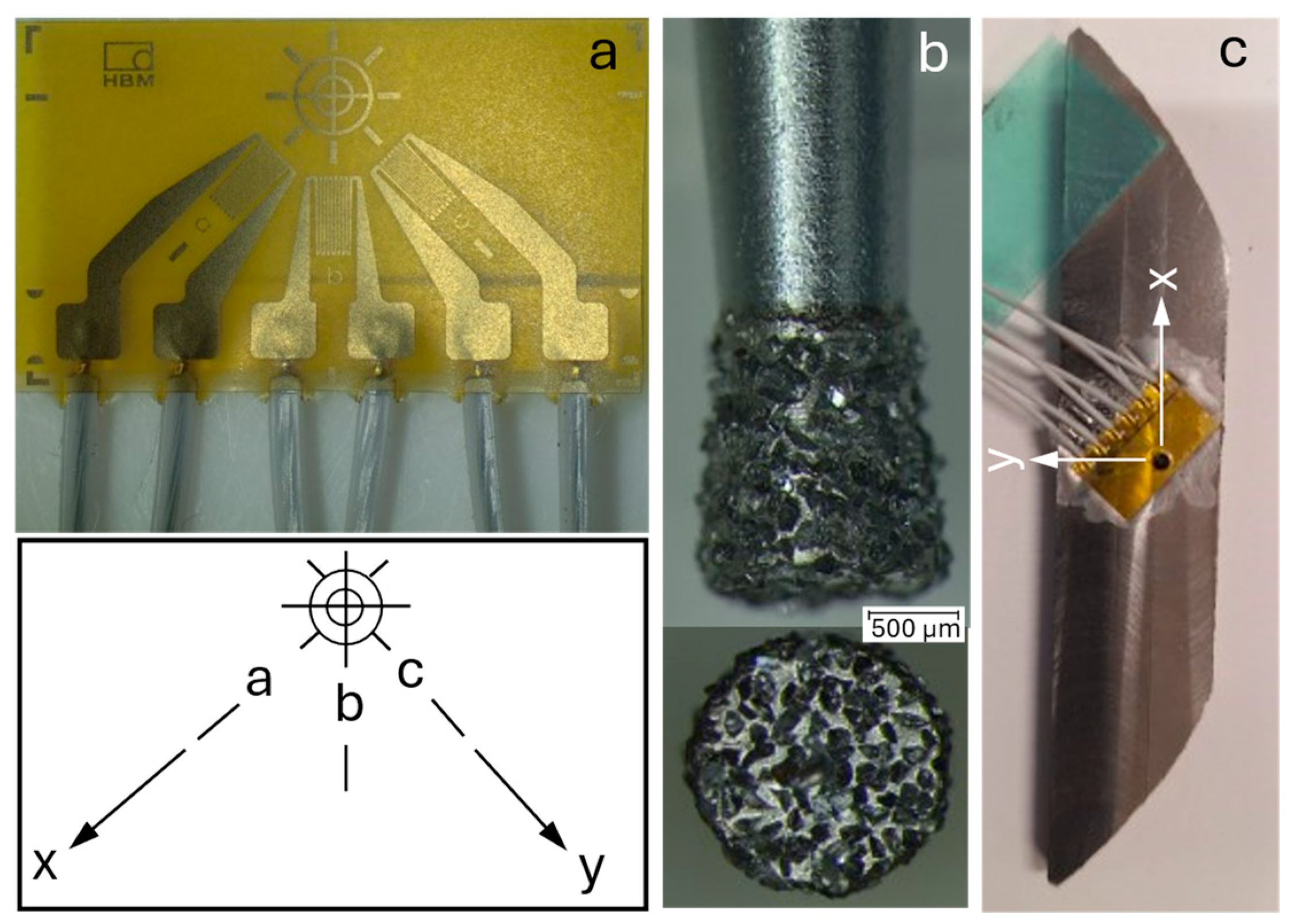
The hole-drilling equipment used was the MTS3000-Restan with EVAL 6.0 software (Sint Technology; Calenzano, Italy). Residual stress measurements were performed using a three-element rectangular strain gauge rosette HBK/HBM, type 1-RY61-1.5/120R3 (Hottinger Brüel & Kjær, Darmstadt, Germany), specifically designed for the hole-drilling method in accordance with ASTM E837. The rosette comprises three constantan measuring grids oriented at 0°, 45°, and 90° in a counter-clockwise arrangement, with a nominal resistance of 120 Ω, a grid length of 1.5 mm and a strain gauge radius, SG, of 2.550 mm. The sensing grids were mounted on a polyimide backing. The strain gauge rosettes were bonded to the specimen surface using a two-component Grip Cement adhesive system (Micro-Measurements®, Raleigh, NC, USA), consisting of Grip Cement Liquid (Part No. 100-011506) and Grip Cement Powder (Part No. 100-011505). The adhesive was prepared and applied according to the manufacturer’s recommendations to ensure adequate strain transfer and bonding quality during residual stress measurements. The orientation of the rosette on the sample surface was selected according to the strain gauge manufacturer, Figure 4a,c, with the X-axis aligned with the machining direction. To drill the holes, a diamond-coated inverted cone drill bit with a diameter of 1.6 mm was used.
Figure 4.
(a) Schematic representation of the HBK/HBM 1-RY61-1.5/120R3 rosette showing the axis directions. (b) Diamond-coated inverted-cone drill bit. (c) Strain gauge rosette mounted on the sample surface.
The calculation depth was established as 39.2% of SG. Thus, the ratio Dhole/2SG was 0.337 and was used in the residual stress calculations according to ASTM E837. Different step depths were tested, namely 0.25 and 0.125 mm, and the most stable results were found with 0.125 mm. Depth increments of 0.25 mm-steps resulted in highly scattered residual stress results, exhibiting pronounced oscillations in both magnitude and sign.
3. Results and Discussion
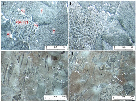
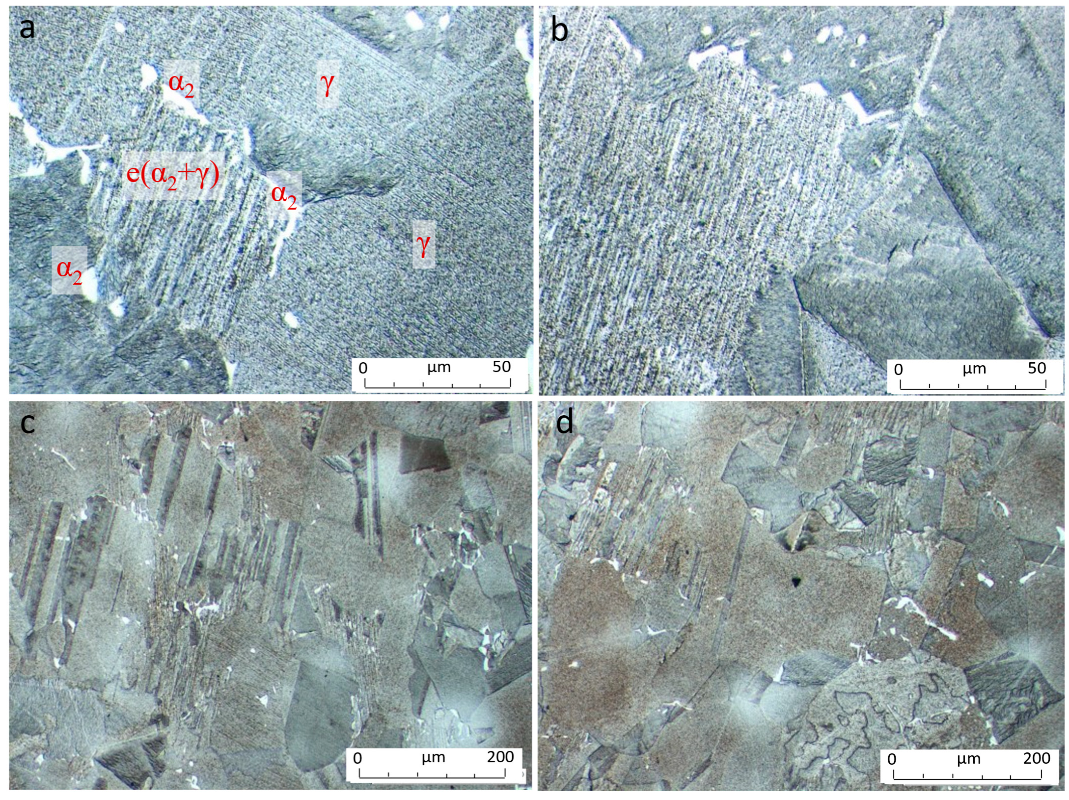
The microstructure of the vacuum arc remelting, VAR, processed Ti-48Al-2Cr-2Nb exhibits a duplex character, consisting of equiaxed γ grains with sizes ranging from approximately 20 to 40 μm and α2 + γ lamellar colonies with characteristic dimensions on the order of 50 to 100 μm. In addition, a small fraction of retained α2 phase is present in the form of dispersed bright particles, as shown in Figure 5.
Figure 5.
Representative microstructure of the VAR-cast Ti48Al2Cr2Nb exhibiting a duplex morphology. (a,b) Identification of the main microstructural constituents, including equiaxed γ grains, the α2 phase, and α2 + γ lamellar colonies. (c,d) General views of the microstructure showing a homogeneous distribution of equiaxed γ grains and lamellar colonies.
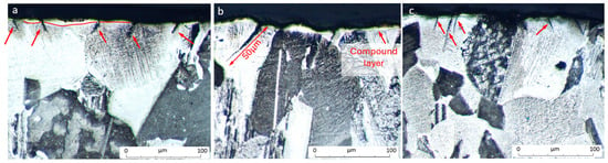
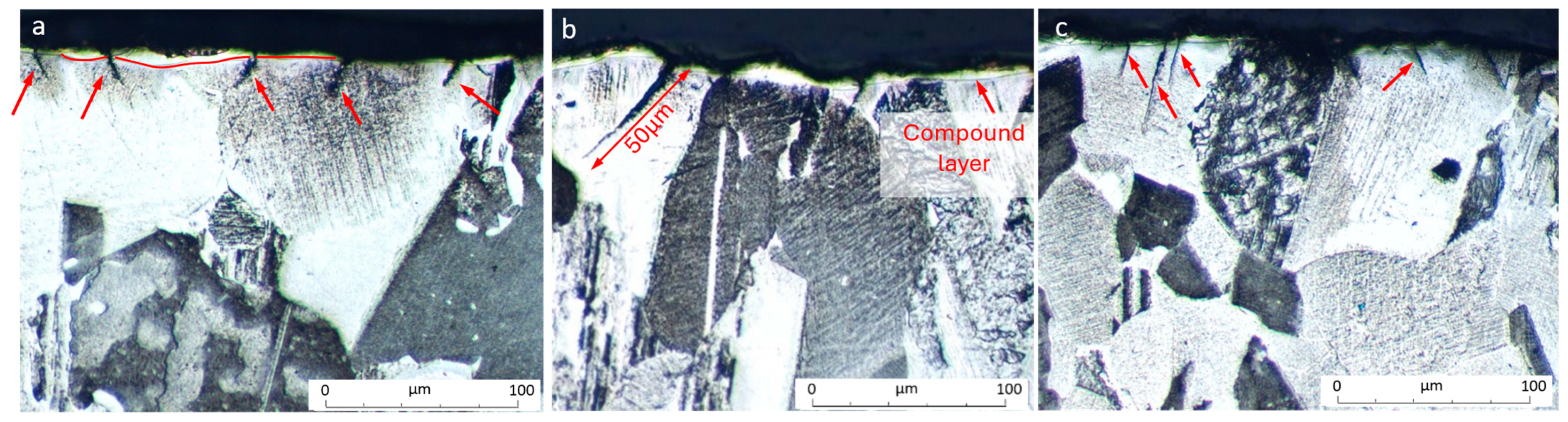
W-EDM resulted in the formation of a surface compound layer and associated microcracking, as shown in Figure 6. Numerous microcracks were observed within the W-EDM-affected surface layer. Surface microcracks generated during W-EDM were observed to initiate within the recast/compound layer and propagate towards the substrate. However, crack growth remained highly localized, with typical penetration depths not exceeding approximately 50 μm. This value is comparable to the characteristic size of the α2/γ lamellar colonies in those areas, suggesting that colony boundaries act as effective barriers to further crack propagation. Consequently, the damage induced by W-EDM is largely confined to the near-surface region.
Figure 6.
Cross-sectional micrographs of the W-EDM-machined surface showing the formation of a compound layer and surface microcracks. (a,c) General view highlighting crack initiation sites along the machined surface. (b) Detail view a of a crack approximately 50 μm in length propagating from the compound layer into the substrate.
The shallow cracks observed on the W-EDM-cut surface are attributed to thermally induced stresses generated by the severe temperature gradients associated with the EDM process. Although a quantitative statistical analysis of crack density was beyond the scope of the present work, the observations consistently revealed a homogeneous distribution of microcracks along the machined perimeter, with crack spacing typically on the order of a few tens of micrometres. The rapid heating of the surface layer, combined with the restricted thermal expansion imposed by the underlying material and the subsequent contraction during cooling, may promote localized tensile stresses and crack formation. The absence of significant microstructural evidence of extensive remelting suggests that thermal strain incompatibilities, rather than solidification-induced cracking, constitute the dominant cracking mechanism. Their limited penetration depth suggests that the damage is confined to the recast layer and the immediately underlying material. This interpretation is further supported by the microhardness profile, which remains essentially constant from the machined surface towards the bulk material, revealing no evidence of significant hardening or softening associated with an extended heat-affected zone. Therefore, the observed microcracks are believed to result from localized thermal contraction of the thermally affected surface layer combined with the intrinsically brittle nature of γ-TiAl alloys, rather than from substantial subsurface microstructural modifications or deeply penetrating residual stress fields.
Comparison between the cross-sectional micrographs acquired near the W-EDM surface and those obtained from the bulk material reveals the presence of a thin surface-modified layer. Beneath this altered surface region, the material retains a duplex microstructure characterized by coarse α2 + γ lamellar colonies, as shown in Figure 5b,c. The colony dimensions observed below the W-EDM surface are comparable to those found in the bulk material, typically ranging from approximately 50 to 150 μm and occasionally exceeding 200 μm. These observations suggest that the effects of the W-EDM process are mainly confined to the immediate vicinity of the machined surface, while no substantial modification of the colony-scale microstructure was identified in the underlying material based on the present metallographic observations.
3.1. Microstructural Effects of Face Milling
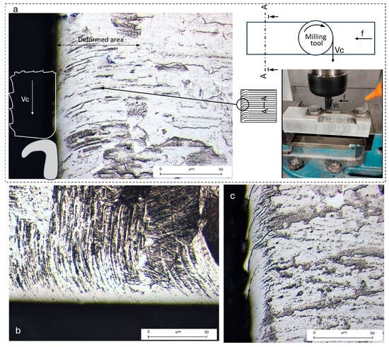
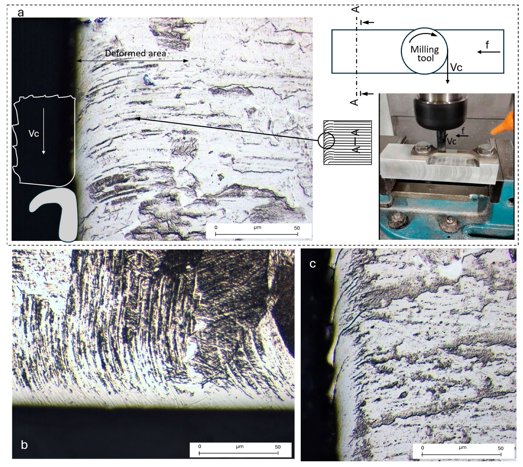
Cross-sectional examination of the machined surface revealed the presence of a plastically deformed subsurface layer directly beneath the machined surface (Figure 7). The microstructural constituents located in this region exhibit a pronounced curvature and elongation parallel to the cutting direction, indicating severe plastic flow during material removal. This deformation is particularly evident in the lamellar colonies, whose originally straight lamellae become progressively bent as the surface is approached. The observed plastic deformation can be attributed not only to the severe mechanical loading imposed by the cutting process, but also to the intense localized heating generated at the tool–workpiece interface. Owing to the relatively low thermal conductivity of γ-TiAl alloys, a significant fraction of the generated heat is concentrated within the near-surface region, promoting thermal softening and facilitating plastic deformation of the microstructure during machining. The affected region extends several tens of micrometres below the machined surface, reaching an approximate depth of 20 to 40 μm, depending on the local microstructural orientation. Below this layer, the microstructure recovers its original morphology, characterized by undeformed α2 + γ lamellar colonies and equiaxed γ grains. No evidence of surface cracking, material pull-out, white-layer formation, or microstructural phase transformations was observed at the scale analyzed.
Figure 7.
(a) Representative cross-sectional micrograph of the machined surface after face milling (V = 100 m/min; dry milling). A plastically deformed subsurface region is observed beneath the machined surface, where the lamellar microstructural constituents exhibit pronounced bending along the cutting direction. The corresponding milling configuration and cutting kinematics are shown schematically. (b) Microstructure obtained under the V = 50 m/min-MQL condition. (c) Microstructure obtained under the V = 100 m/min-dry condition.
In Figure 7b, corresponding to the MQL condition at V = 50 m/min, the microstructure exhibits a relatively homogeneous and continuous surface layer, while the lamellar colonies remain clearly distinguishable almost up to the machined surface. Only slight bending and deformation of the lamellae can be observed in the near-surface region, with no evident disruption of the lamellar morphology. Furthermore, no distinct white transformation layer or significant surface cracking is visible. These observations suggest that despite the local heating generating during machining, the milling process mainly induced localized plastic deformation, residual stress development, and possibly a very shallow microstructural refinement (<10–20 μm). However, the thermal load was apparently insufficient to cause severe metallurgical alterations.
In Figure 7c, corresponding to the V = 100 m/min dry-machining condition, the micrograph depicts a markedly different near-surface condition. A continuous surface layer approximately 5 to 15 μm thick can be distinguished, within which the original lamellar structure becomes difficult to identify. This region exhibits a more homogeneous and diffuse appearance, indicating a higher degree of microstructural distortion than that observed under MQL conditions. These features suggest substantially greater thermo-mechanical loading during machining. The affected region is likely associated with severe plastic deformation promoted by the elevated temperatures generated under dry cutting conditions, which increase the local deformability of the material and lead to distortion of the lamellar morphology, rather than to recrystallization phenomena, since no reduction in surface hardness was observed. In addition to the heavily deformed surface layer, the dry-machined specimens exhibited localized surface discontinuities in the form of shallow notch-like defects. These features are likely related to intensified tool–workpiece interactions under dry machining conditions, where elevated temperatures may promote adhesion phenomena followed by material detachment. The occurrence of such discontinuities further supports the higher thermo-mechanical severity of dry machining compared with MQL-assisted machining.
Overall, compared to the MQL-assisted condition at 50 m/min, dry milling at 100 m/min resulted in a more pronounced machining-affected layer and a lower degree of preservation of the lamellar microstructure near the machined surface. The increased thermal and mechanical loads associated with the absence of lubrication and the higher cutting speed promoted lamellar distortion and microstructural degradation within the first micrometres beneath the surface. Nevertheless, no evidence of a continuous transformed layer or severe surface cracking was observed, indicating that the machining-induced damage remained limited to a shallow near-surface region.
3.2. Effect on Surface Hardness
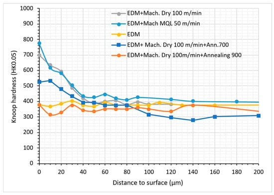
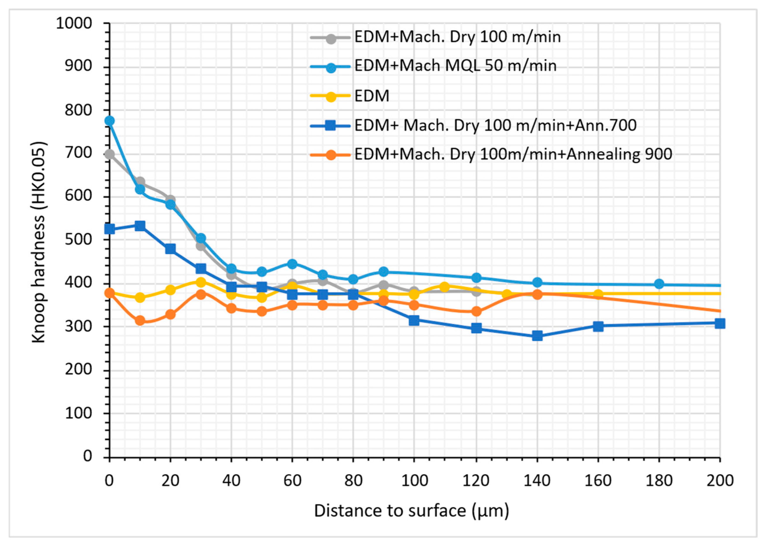
Figure 8 shows the microhardness profiles for the different test conditions. Two additional profiles corresponding to annealing treatments performed after dry machining at 100 m/min are also included and will be discussed in a later section.
Figure 8.
Microhardness profiles measured from the surface into the subsurface region of the Ti48Al2Cr2Nb alloy under different processing conditions.
The microhardness profiles reveal a significant influence of the post-EDM machining conditions on the near-surface mechanical response. The highest hardness values were obtained for the EDM surface subsequently machined under MQL at 50 m/min, reaching approximately 780 HV at the outermost surface. The EDM surface machined under dry conditions at 100 m/min also exhibited pronounced hardening, although with lower surface values, around 700 HV. In contrast, the EDM condition showed only moderate hardness values close to 550 HV, indicating that the wire EDM process itself did not induce significant surface hardening.
The superior hardness obtained under MQL conditions can be attributed to the retention of machining-induced strain hardening while preserving the original microstructural features of the γ-TiAl alloy. Conversely, the more severe thermal conditions associated with dry machining promote greater near-surface microstructural alteration, which may lead to partial relaxation of the deformation-induced hardening, and consequently, to lower hardness values. Hardness evolution is generally influenced by several factors, including phase distribution, grain size, defect density and residual stress state. In the present study, the available experimental evidence indicates that the dominant contribution arises from the severe plastic deformation introduced during post-EDM machining. The substantial hardness increase observed under both dry and MQL conditions is consistent with the formation of a highly strained surface layer containing a high density of machining-induced dislocations. Since no significant changes in phase distribution were identified in the analyzed conditions, the observed hardness variations are primarily attributed to differences in strain hardening and stored deformation energy. The exceptional hardness measured after MQL machining suggests the formation of a severely deformed surface layer characterized by a high dislocation density and a large amount of stored strain energy.
Furthermore, both post-machining conditions exhibited a progressive decrease in hardness with increasing depth below the surface. Beyond approximately 100 μm, the hardness values tended to converge to those of the bulk material, indicating that the machining-induced modifications were essentially confined to a shallow subsurface layer.
The results indicate that the post-machining operation exerts a stronger influence on near-surface hardening than EDM alone. The exceptional hardness measured after MQL machining suggests the formation of a severely deformed surface layer characterized by a high dislocation density and possible microstructural refinement. Similar relationships between severe plastic deformation, work hardening, and altered surface integrity have been widely reported in machining studies [26,27].
Although microhardness measurements cannot directly quantify residual stresses, the combination of a pronounced hardness increase and an extended hardened subsurface region is generally considered indicative of substantial machining-induced material deformation. According to Guo et al. [28], residual stresses and hardness modifications are often interconnected manifestations of the same thermo-mechanical loading history experienced during machining. Therefore, the markedly higher hardness observed for the EDM + MQL condition may be associated with a higher level of residual stress generation compared with the dry and EDM conditions, although direct residual stress measurements would be required for confirmation. Furthermore, the greater hardness achieved under MQL compared to dry machining indicates that the thermo-mechanical conditions generated during machining have a significant influence on the near-surface response of the material. Although the mechanisms responsible for this behavior cannot be conclusively established from the present results, the higher hardness values obtained under MQL suggest that this lubrication strategy favours the retention of surface hardening compared with dry machining. Consequently, the MQL condition resulted in the highest near-surface hardness among the machining conditions investigated.
3.3. Analysis of Residual Stresses
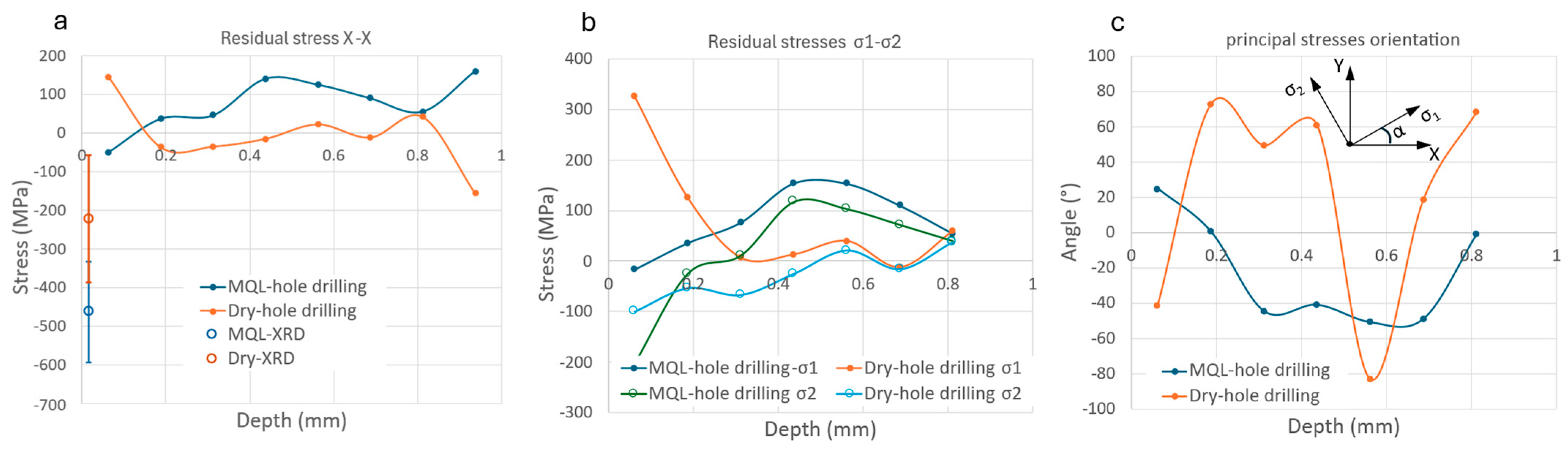
The reported residual stress at the sample surfaces corresponds to the average of nine independent XRD measurements (three measurements on each of three specimens), and the values are represented in Figure 9. Thus, the experimental standard deviation of the mean value was estimated from the measured nominal values. As can be observed, a severe compressive residual stress tendency exists on the surface of the machined sample, regardless of the lubrication condition. However, the experimental standard deviation is too high. This is because the measurement uncertainty of the method varies from 58 to 330 MPa, and from 142 to 211 MPa in the measurements under dry and MQL conditions, respectively. Although considerable scatter is observed in the measurements, the predominance of compressive residual stresses is consistent with the complex thermo-mechanical phenomena occurring during machining, where plastic deformation, frictional effects, and local temperature gradients interact to determine the final stress state within the near-surface region [20,29]. Nevertheless, the standard deviation reported for each residual stress measurement represents the statistical uncertainty associated with the analysis of the diffraction data, and is calculated by the instrument software from the scatter of the experimental diffraction-ring data around the fitted stress model. Therefore, it reflects the quality of the diffraction pattern, counting statistics, material texture, grain-size effects, and measurement noise. In the present study, the relatively large standard deviations associated with the XRD measurements are attributed to the coarse lamellar colony microstructure of the γ-TiAl alloy together with the heterogeneous deformation introduced by machining. The limited number of diffracting colonies within the irradiated volume, combined with local strain gradients in the near-surface layer, can increase the scatter of diffraction peak positions and consequently the uncertainty of residual stress determination. In addition, the use of a Cr Kα radiation source may have further contributed to the measurement uncertainty because of its relatively low penetration depth in γ-TiAl alloys. Consequently, the diffracting volume is restricted to a shallow surface layer affected by machining-induced deformation and contains a limited number of lamellar colonies, which may increase the scatter in the measured residual stresses.
Figure 9.
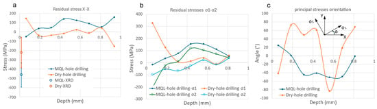
Residual stresses corresponding to samples machined at dry-V 100 m/min and MQL-V 50 m/min conditions (f = 0.01 mm/rev; p = 0.2 mm). (a) Residual stresses in the X-direction (machining direction). (b) Principal residual stresses (σ1 and σ2) as a function of depth (hole-drilling method). (c) Orientation angle of the principal stresses relative to the reference X-axis as a function of depth.
Considering the magnitude of the experimental uncertainty associated with the XRD measurements, small differences between the residual stress values obtained under dry and MQL conditions cannot be regarded as statistically significant. Therefore, the XRD results should be interpreted primarily in terms of the overall residual stress state rather than the absolute differences between machining conditions. In this regard, both machining conditions consistently exhibited a predominantly compressive residual stress state at the machined surface.
Figure 9a compares the residual stresses measured at the immediate surface by XRD with those determined at increasing depths by the hole-drilling technique, allowing the evolution of the stress state from the surface to the subsurface region to be assessed. In the MQL condition, the residual stresses evolve from slightly compressive values near the surface, approximately −50 MPa at a depth of 0.05 mm, to a predominantly tensile regime throughout nearly the entire subsurface region analysed. The maximum value is reached at a depth of approximately 0.45–0.50 mm, where the residual stress approaches 140 MPa. Beyond this point, a gradual decrease to approximately 50 MPa at 0.8 mm is observed. The residual stress value measured at a depth of 0.9 mm depth may be excluded from the discussion because it is located at the limit of the effective measurement range. At this depth, the sensitivity of the strain-gauge rosette to stress relaxation decreases significantly, leading to greater uncertainty in the inverse calculation of residual stresses [30]. Overall, the profile exhibits a relatively stable and predominantly tensile stress distribution.
In contrast, the dry condition displays a considerably more irregular residual stress profile. The first hole-drilling increment exhibits a tensile residual stress of approximately 140 MPa, followed by a rapid decrease towards compressive values between 0.15 and 0.45 mm depth. Beyond this region, the stresses increase again, reaching slightly tensile values at around 0.55 mm. The measurement obtained at the final depth is not considered further in the discussion. This behavior suggests a more complex interaction between the thermal and mechanical phenomena generated during dry machining. A comparison of both conditions suggests that the use of MQL may result in a more gradually varying residual stress profile with smaller fluctuations throughout the analyzed depth. However, given the experimental scatter associated with the surface XRD measurements, these differences should be interpreted with caution. In contrast, dry machining produces pronounced stress gradients and repeated transitions between tensile and compressive states. This finding may be associated with the lower friction and thermal loads generally reported for MQL-assisted machining. Although both conditions exhibit strong surface compression according to XRD measurements, only dry machining develops a tensile subsurface stress state already detectable within the first hole-drilling increment.
The apparent discrepancy between XRD and hole-drilling measurements is attributed to the different sampling depths of the two techniques. XRD mainly probes the first few micrometres beneath the machined surface, where severe plastic deformation and high compressive residual stresses are expected. In contrast, hole drilling provides an average stress state over a substantially larger subsurface volume. The results suggest the existence of a steep residual-stress gradient between the depth sampled by XRD and the first hole-drilling increment.
Figure 9b depicts the principal stresses σ1 and σ2. The analysis of principal residual stresses offers a more complete description of the subsurface stress state than the σx component alone. By analysing the principal stresses, the maximum and minimum stress levels can be identified independently of the reference coordinate system, thereby providing a more representative assessment of the residual stress field.
The principal stress representation reveals that dry machining exhibits a higher degree of stress anisotropy in the near-surface region, characterised by the coexistence of large tensile and compressive principal stresses. In contrast, MQL machining produces a less anisotropic and more gradually varying residual stress field throughout most of the analyzed depth. Although metallographic observations revealed a machining-affected layer of less than 50 μm (Figure 7), the residual-stress profiles obtained by hole drilling indicate that the influence of machining extends to substantially greater depths. This behavior is not unexpected, since residual stresses may penetrate well beyond the region where microstructural alterations can be directly identified by microscopy. Whereas the machining-affected layer reflects local microstructural changes, the residual-stress field must satisfy mechanical equilibrium and may therefore extend several hundred micrometres beneath the surface. Interestingly, this thickness is comparable to the depth of the first hole-drilling increment. Therefore, while XRD measurements predominantly characterise the highly deformed near-surface region, the first hole-drilling data point represents a depth-averaged stress state influenced by both the machining-affected layer and the underlying subsurface material. The marked difference between the XRD and hole-drilling results is consistent with the existence of a pronounced residual-stress gradient within the machining-affected layer, with the highly compressive stresses detected by XRD being primarily confined to the immediate vicinity of the surface and progressively relaxing over the first few tens of micrometres below it.
The orientation of the principal stresses (Figure 9c) provides additional evidence of the different residual-stress states generated by dry and MQL machining. MQL machining exhibits a comparatively stable principal-stress orientation throughout most of the analyzed depth, suggesting a more consistent redistribution of residual stresses beneath the machined surface. In contrast, dry machining shows larger angular variations, particularly within the near-surface region, indicating a more heterogeneous and anisotropic residual-stress field. However, some of the abrupt angle changes observed under dry conditions should be interpreted with caution, as they occur at depths where the difference between the principal stresses becomes relatively small. Under these conditions, the orientation of the principal stresses becomes increasingly sensitive to minor variations in the measured stress components, which may lead to large fluctuations in the calculated angle without necessarily reflecting a significant physical rotation of the residual-stress field. Nevertheless, the overall trend suggests that MQL promotes a more stable residual-stress state, not only in terms of stress magnitude, but also with respect to the orientation of the principal stress field.
3.4. Influence of Heat Treatments on Surface Integrity
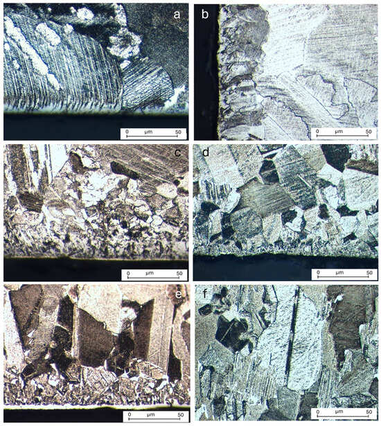
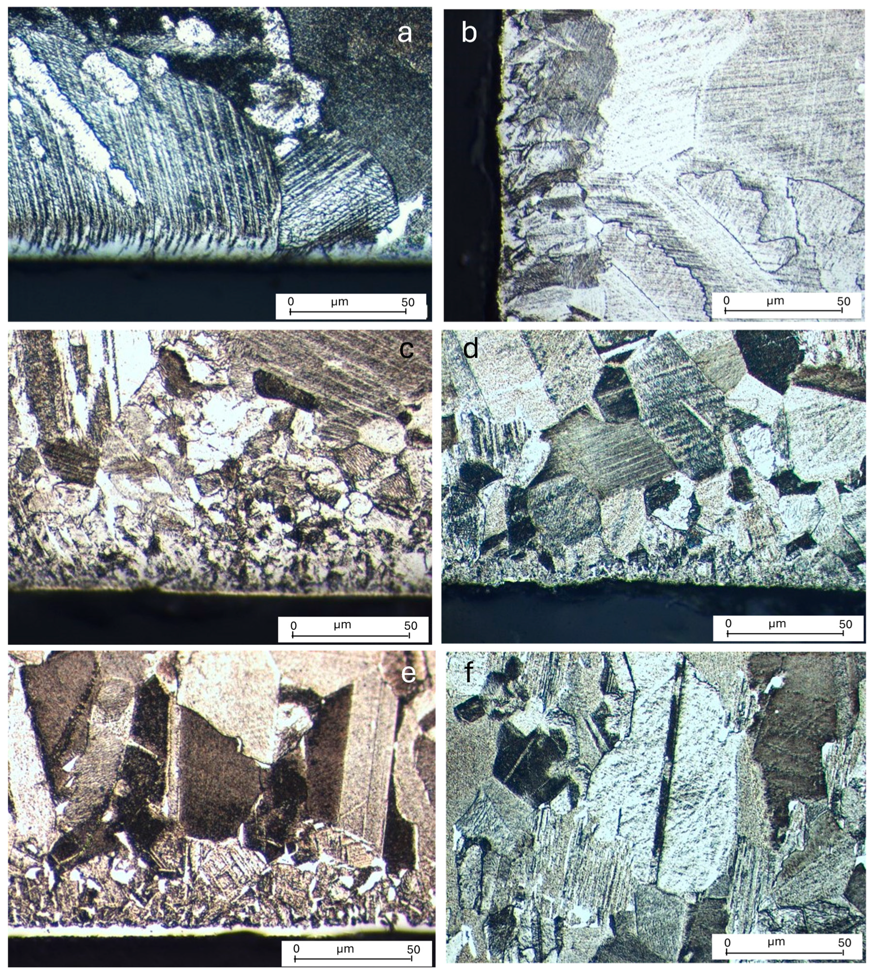
Figure 10 shows the evolution of the surface microstructure of the EDM-machined specimens after annealing for 2 h at temperatures between 700 and 1100 °C. After annealing at 700 °C, the heavily deformed surface layer generated by the post-EDM machining process remained clearly visible. The elongated and distorted microstructural features observed near the surface indicate that recrystallization was not activated under these conditions. This observation is consistent with the microhardness results (Figure 8), which revealed significantly higher hardness values in the near-surface region compared with the bulk material, indicating that the strain-hardening effect induced by machining was largely preserved. Nevertheless, although no evidence of surface recrystallization was observed after annealing at 700 °C for 2 h, a slight reduction in surface hardness was detected compared with the as-machined condition. This behavior suggests the occurrence of recovery processes involving partial rearrangement and annihilation of machining-induced dislocations and a concomitant relaxation of residual stresses. However, the persistence of the heavily deformed surface layer and the hardness values—still significantly above those of the bulk material—indicate that recrystallization was not activated under these conditions. Recovery is a thermally activated restoration mechanism that reduces the density of crystalline defects generated during machining through dislocation rearrangement and annihilation. Although this process decreases the stored strain energy and may lead to a reduction in hardness, it does not involve the formation of new strain-free grains. Therefore, the persistence of the heavily deformed surface morphology after annealing at 700 °C is consistent with recovery rather than recrystallization.
Figure 10.
Surface and subsurface microstructures of the Ti-48Al-2Cr-2Nb alloy after EDM followed by machining and subsequent annealing treatments. (a) Dry machining at 100 m/min + annealing at 700 °C for 2 h. (b) Dry machining at 100 m/min + annealing at 900 °C for 2 h. (c) MQL machining at 50 m/min + annealing at 900 °C for 2 h. (d) Dry machining at 100 m/min + annealing at 1000 °C for 2 h. (e) MQL machining at 50 m/min + annealing 1100 °C for 2 h. (f) Bulk material microstructure after dry machining at 100 m/min and annealing at 1000 °C for 2 h. The annealing treatments promoted recovery and recrystallization within the machining-affected layer, while the bulk microstructure remained essentially unchanged.
A markedly different behavior was observed after annealing at 900 °C. A recrystallized layer approximately 50 μm thick developed at the surface, replacing the previously deformed region. The recrystallized grains were considerably finer than those of the underlying bulk microstructure, suggesting extensive nucleation within the highly strained layer generated during machining. Similar complete recrystallization at 900 °C was also observed in the EDM specimens subsequently machined under MQL conditions at 50 m/min, indicating that this temperature is sufficient to restore the machining-affected layer regardless of the post-EDM machining strategy employed. Recrystallization involves the nucleation and growth of new strain-free grains within a previously deformed microstructure. In the present study, its occurrence is supported by the replacement of the distorted surface layer by a fine-grained microstructure together with the significant decrease in hardness towards values close to those of the unaffected bulk material. Furthermore, the thickness of the transformed layer closely matches that of the previously deformation-affected zone, suggesting that the stored deformation energy introduced during machining provided the driving force required for recrystallization. Although no EBSD analysis was performed to quantitatively determine the recrystallized fraction, the combined microstructural and microhardness evidence is consistent with a nearly complete recrystallization of the machining-affected layer. Increasing the annealing temperature to 1000 °C did not produce significant modifications in either the thickness of the recrystallized layer or its general morphology. The microstructure remained very similar to that observed after annealing at 900 °C, and no clear evidence of substantial grain growth within the recrystallized zone was identified. Annealing at 1100 °C led to the formation of an external oxidation layer, despite the use of an argon atmosphere during heat treatment. However, the underlying recrystallized layer exhibited a morphology similar to that observed after annealing at 900 and 1000 °C. The recrystallized region maintained a thickness similar to that observed at lower annealing temperatures and retained a much finer grain size than the bulk material.
An important observation is that the thickness of the recrystallized layer formed after annealing at 900–1100 °C closely matches that of the heavily deformed layer observed after annealing at 700 °C. This correspondence strongly suggests that recrystallization was confined to the region affected by severe plastic deformation during post-EDM machining. Therefore, the driving force for recrystallization can be attributed primarily to the high density of crystalline defects and the stored strain energy introduced during machining. Once recrystallization was completed at 900 °C, further increases in temperature up to 1100 °C did not produce significant microstructural changes, indicating that the restoration process had already been completed at the lower temperature.
The combined microstructural and microhardness results indicate that the transition from a hardened and highly deformed surface layer to a fully recrystallized microstructure occurs between 700 and 900 °C. Consequently, 900 °C can be considered a critical temperature for the complete restoration of the machining-affected layer, leading to the removal of work-hardening effects and to a significant reduction in the residual stresses associated with the machining process.
No significant differences in the overall distribution of the α phase, eutectoid constituent and γ phase were observed between the as-machined and annealed conditions. The microstructure remained homogeneous throughout the analyzed sections, with the main changes being restricted to the near-surface region affected by machining. In this region, annealing at 700 °C promoted recovery processes, whereas annealing at 900 °C and above led to complete recrystallization of the previously deformed layer. No significant grain growth was observed in the bulk material after any of the annealing treatments. The coarse lamellar grains retained a morphology and size similar to those of the as-machined condition, indicating that the thermal treatments did not induce substantial microstructural evolution in the material core. This behavior is expected because the annealing temperatures employed (700–1100 °C) are well below the relevant phase-transformation and solvus temperatures of the Ti-Al system. Consequently, microstructural modification is confined to the heavily deformed surface layer, where the high density of machining-induced defects provides sufficient stored energy to drive recovery and recrystallization. Therefore, the observed microstructural evolution is associated primarily with restoration phenomena rather than with significant changes in phase distribution within the material.
4. Conclusions
This work provides an integrated assessment of the effects of EDM, subsequent machining and post-process annealing on the surface integrity of γ-TiAl alloys. The results establish clear relationships between machining-induced plastic deformation, hardness evolution, residual stress relaxation, recovery and recrystallization of the affected surface layer. Furthermore, the temperature range required for the restoration of the machining-affected layer was identified, demonstrating that complete recrystallization occurs at approximately 900 °C. Based on microstructural characterization, microhardness measurements, and residual stress analyses, the main findings of this study can be summarized as follows:
- W-EDM processing generated surface cracking and an altered near-surface layer. Given the inherently brittle nature of γ-TiAl alloys, these defects may compromise the surface integrity of the component and should therefore be carefully considered in manufacturing routes.
- Dry milling at 100 m/min and MQL milling at 50 m/min successfully removed the cracked layer generated by W-EDM, producing a defect-free surface. However, the machining operation introduced a heavily deformed subsurface layer approximately 50 μm thick.
- The machining-induced deformation increased the surface and subsurface microhardness and generated residual stresses, evidencing a significant modification of the alloy surface integrity.
- Annealing treatments progressively restored the integrity of the machining-affected layer. Annealing at 700 °C for 2 h resulted only in partial recovery, whereas annealing at 900 °C and above promoted microstructural and hardness changes consistent with the complete recrystallization of the deformed layer. The recrystallized layer thickness closely matched that of the deformation-affected zone, indicating that the stored deformation energy introduced during machining was the main driving force for recrystallization. Surface oxidation was observed after annealing at 1100 °C.
- Among the machining conditions investigated, dry milling at 100 m/min followed by annealing at 900 °C for 2 h constitutes an effective strategy for removing the surface defects associated with W-EDM while restoring the surface integrity of the Ti-48Al-2Cr-2Nb alloy without altering the bulk microstructure.
Some limitations of the present study should be acknowledged. Although the microstructural observations clearly revealed the onset and completion of recrystallization, the use of optical microscopy alone did not enable a quantitative assessment of grain growth within the recrystallized layer. Further EBSD analyses and residual stress measurements after annealing would be beneficial for achieving a more detailed understanding of the restoration mechanisms involved.
Author Contributions
Conceptualization, V.M. and A.M.-M.; methodology, A.M.-M., C.T. and J.C.; software, E.G.-M. and V.M.; validation, V.M., C.R. and A.M.-M.; formal analysis, V.M.; investigation, A.M.-M., C.T., J.C., M.C.M., E.G.-M. and C.R.; resources, V.M. and C.R.; data curation, V.M., A.M.-M., C.R. and C.T.; writing—original draft preparation, V.M., M.C.M. and E.G.-M.; writing—review and editing, C.R., V.M., A.M.-M. and J.C.; visualization, E.G.-M., A.M.-M. and V.M.; supervision, V.M., A.M.-M. and C.R.; project administration, V.M. and J.C.; funding acquisition, V.M., J.C., A.M.-M., M.C.M., E.G.-M. and C.R. All authors have read and agreed to the published version of the manuscript.
Funding
This work is part of research project SBPLY/23/180225/000132, funded by the European Union through the European Regional Development Fund (ERDF) and by the Regional Government of Castilla-La Mancha (JCCM) through the INNOCAM programme.
Data Availability Statement
The data supporting this study are included in the article. Further inquiries may be directed to the corresponding author.
Acknowledgments
The authors wish to thank Vasile Alecsandri University for providing access to its facilities for the residual stress measurements. During the preparation of this manuscript, the authors used Microsoft 365 Copilot (GPT-5 Chat, Microsoft). for grammar checking, language editing, and corrections to improve the readability of the manuscript. The authors have reviewed and edited the output and take full responsibility for the content of this publication.
Conflicts of Interest
The authors declare no conflicts of interest.
References
- Güther, V.; Allen, M.; Klose, J.; Clemens, H. Metallurgical processing of titanium aluminides on industrial scale. Intermetallics 2018, 103, 12–22. [Google Scholar] [CrossRef] [Scilit]
- Bewlay, B.P.; Nag, S.; Suzuki, A.; Weimer, M.J. Titanium aluminides in commercial aircraft engines. Mater. High Temp. 2016, 33, 549–559. [Google Scholar] [CrossRef] [Scilit]
- García-Martínez, E.; Miguel, V.; Martínez-Martínez, A.; Coello, J.; Naranjo, J.A.; Manjabacas, M.C. Optimization of the dry turning process of Ti48Al2Cr2Nb aluminide based on the cutting tool configuration. Materials 2022, 15, 1472. [Google Scholar] [CrossRef] [Scilit]
- Liu, X.; Lin, Q.; Zhang, W.; Van Horne, C.; Cha, L. Microstructure design and its effect on mechanical properties in gamma titanium aluminides. Metals 2021, 11, 1644. [Google Scholar] [CrossRef] [Scilit]
- Wagner, D.; Clemens, H.; Mayer, S. Microstructural characterization and spark plasma sintering of multi-phase γ-TiAl alloys. Materials 2019, 12, 1523. [Google Scholar] [CrossRef] [Scilit]
- Mantle, A.L.; Aspinwall, D.K. Surface integrity of a high speed milled gamma titanium aluminide. J. Mater. Process. Technol. 2001, 118, 143–150. [Google Scholar] [CrossRef] [Scilit]
- Aspinwall, D.K.; Dewes, R.C.; Mantle, A.L.; Soo, S.L.; Phillips, T. The machining of γ-TiAl intermetallic alloys. CIRP Ann.-Manuf. Technol. 2005, 54, 99–104. [Google Scholar] [CrossRef] [Scilit]
- Beranoagirre, A.; Olvera, D.; López de Lacalle, L.N. Milling of gamma titanium-aluminum alloys. Int. J. Adv. Manuf. Technol. 2012, 62, 83–88. [Google Scholar] [CrossRef] [Scilit]
- Hussain, A.; Layegh, S.E.; Lazoglu, I.; Arrazola, P.-J.; Lazcano, X.; Aristimuño, P.-X.; Subasi, O.; Yigit, I.E.; Öztürk, Ç.; Yavaş, Ç. Mechanics of milling 48-2-2 gamma titanium aluminide. CIRP J. Manuf. Sci. Technol. 2020, 30, 131–139. [Google Scholar] [CrossRef] [Scilit]
- Anurag, S. Wire-EDM: A potential manufacturing process for gamma titanium aluminides in future aero engines. Int. J. Adv. Manuf. Technol. 2018, 95, 135–147. [Google Scholar] [CrossRef] [Scilit]
- Sun, L.; Shi, S.; Li, X.; Hou, Y.; Chu, Z.; Chen, B. Surface microstructure evolution and mechanical property investigation of Inconel 718 alloy using multiple trimmings and WEDM. Exp. Tech. 2024, 49, 299–312. [Google Scholar] [CrossRef] [Scilit]
- Wang, X.; Liu, Y.; Wang, Z.; Huang, L. Study on surface roughness, hardened layer, residual stress, and mechanical properties of γ-TiAl alloys produced by ultrasonic vibration-assisted milling. Int. J. Adv. Manuf. Technol. 2025, 138, 5555–5573. [Google Scholar] [CrossRef] [Scilit]
- Priarone, P.C.; Rizzuti, S.; Rotella, G.; Settineri, L. Tool wear and surface quality in milling of a gamma-TiAl intermetallic. Int. J. Adv. Manuf. Technol. 2012, 61, 25–33. [Google Scholar] [CrossRef] [Scilit]
- Hood, R.; Aspinwall, D.K.; Soo, S.L.; Mantle, A.L.; Novovic, D. Workpiece surface integrity when slot milling γ-TiAl intermetallic alloy. CIRP Ann.-Manuf. Technol. 2014, 63, 53–56. [Google Scholar] [CrossRef] [Scilit]
- Wang, X.; Zhang, X.; Pan, D.; Niu, J.; Fu, X.; Qiao, Y. Tool wear and surface integrity of γ-TiAl cryogenic coolant machining at various cutting speed levels. Lubricants 2023, 11, 238. [Google Scholar] [CrossRef] [Scilit]
- Liu, E.; Xu, Y.; Zhu, B.; Shi, L.; Zhou, H. Investigation of tool wear and surface integrity in turning γ-TiAl alloy under high-pressure cooling. Coatings 2026, 16, 428. [Google Scholar] [CrossRef] [Scilit]
- El-Khabeery, M.M.; Fattouh, M. Residual stress distribution caused by milling. Int. J. Mach. Tools Manuf. 1989, 29, 391–401. [Google Scholar] [CrossRef] [Scilit]
- Fuh, K.-H.; Wu, C.-F. A residual-stress model for the milling of aluminum alloy (2014-T6). J. Mater. Process. Technol. 1995, 51, 87–105. [Google Scholar] [CrossRef] [Scilit]
- Vovk, A.; Sölter, J.; Karpuschewski, B. Finite element simulations of the material loads and residual stresses in milling utilizing the CEL method. Procedia CIRP 2020, 87, 539–544. [Google Scholar] [CrossRef] [Scilit]
- Jiang, X.; Wei, Y.; Zhou, J.; Zhan, K.; Ding, Z.; Liang, S.Y. Residual stress generation and evaluation in milling: A review. Int. J. Adv. Manuf. Technol. 2023, 126, 3783–3812. [Google Scholar] [CrossRef] [Scilit]
- Su, J.-C.; Young, K.A.; Ma, K.; Srivatsa, S.; Morehouse, J.B.; Liang, S.Y. Modeling of residual stresses in milling. Int. J. Adv. Manuf. Technol. 2013, 65, 717–733. [Google Scholar] [CrossRef] [Scilit]
- Chighizola, C.R.; D’Elia, C.R.; Jonsson, J.E.; Weber, D.; Kirsch, B.; Aurich, J.C.; Linke, B.S.; Hill, M.R. The effect of bulk residual stress on milling-induced residual stress and distortion. Exp. Mech. 2022, 62, 1437–1459. [Google Scholar] [CrossRef] [Scilit]
- García-Martínez, E.; Miguel, V.; Manjabacas, M.C.; Martínez-Martínez, A.; Vázquez-Gómez, J. A novel mechanistic-analytical force model for slot milling based on the decomposition into cutting and ploughing actions. J. Manuf. Processes 2026, 165, 445–460. [Google Scholar] [CrossRef] [Scilit]
- Vázquez-Gómez, J.; Martínez-García, E.; Manjabacas, M.C.; Miguel, V.; Martínez-Martínez, A. Friction–Wear Interactions and Tribological Efficiency in the Milling of TiAl Alloys under Dry and MQL Conditions. Int. J. Precis. Eng. Manuf.-Green Technol. 2026; accepted.
- Prevéy, P.S. X-ray Diffraction Residual Stress Techniques. In Metals Handbook; American Society for Metals: Metals Park, OH, USA, 1986; Volume 10, pp. 380–392. Available online: https://www.lambdatechs.com/wp-content/uploads/X-Ray-Diffraction-Residual-Stress-Techniques.pdf (accessed on 25 September 2026).
- Jawahir, I.S.; Brinksmeier, E.; M’Saoubi, R.; Aspinwall, D.K.; Outeiro, J.C.; Meyer, D.; Umbrello, D.; Jayal, A.D. Surface Integrity in Material Removal Processes: Recent Advances. CIRP Ann.-Manuf. Technol. 2011, 60, 603–626. [Google Scholar] [CrossRef] [Scilit]
- Zou, Z.; Zhang, X.; Gong, W. Research Progress in Multidimensional Prediction of Machining-Induced Surface Residual Stress. Materials 2026, 19, 510. [Google Scholar] [CrossRef] [Scilit]
- Guo, Y.B.; Li, W.; Jawahir, I.S. Surface Integrity Characterization and Prediction in Machining of Hardened and Difficult-to-Machine Alloys: A State-of-Art Research Review and Analysis. Mach. Sci. Technol. 2009, 13, 437–470. [Google Scholar] [CrossRef] [Scilit]
- Soori, M.; Arezoo, B. A Review in Machining-Induced Residual Stress. J. New Technol. Mater. 2022, 12, 64–83. [Google Scholar]
- Grant, P.V.; Lord, J.D.; Whitehead, P.S. The Measurement of Residual Stresses by the Incremental Hole-Drilling Technique, 2nd ed.; Measurement Good Practice Guide No. 53; National Physical Laboratory: Teddington, UK, 2006; Available online: https://eprintspublications.npl.co.uk/2517/ (accessed on 15 September 2026).
Disclaimer/Publisher’s Note: The statements, opinions and data contained in all publications are solely those of the individual author(s) and contributor(s) and not of MDPI and/or the editor(s). MDPI and/or the editor(s) disclaim responsibility for any injury to people or property resulting from any ideas, methods, instructions or products referred to in the content. |
© 2026 by the authors. Licensee MDPI, Basel, Switzerland. This article is an open access article distributed under the terms and conditions of the Creative Commons Attribution (CC BY) license.