


Abstract
Bridges are critical components of transportation networks, and fire accidents can significantly impair their structural integrity, leading to safety risks and major economic losses. This study presents a comprehensive inspection, materials testing, repair, and field load testing program for a full-scale concrete box girder bridge (Delta Bridge, Alexandria, Egypt) following a fire exposure on two spans. A total of 28 concrete core samples were extracted and tested, revealing average compressive strengths of 48.50 MPa (slab), 53.90 MPa (web), and 45.88 MPa (columns), representing moderate reductions of approximately 8.5%, 7.9%, and 10.8%, respectively, relative to the original in situ concrete strength recorded during construction, and 29.2%, 43.7%, and 30.0% increases over the minimum acceptance limits specified by Egyptian code of practice (ECP 203). Tensile strength tests on reinforcement bars indicated an average yield strength reduction coefficient of 0.87, corresponding to an estimated peak exposure temperature of 600 °C, yet still satisfying Egyptian code requirements (≥500 MPa). Field static load tests using 40-ton tri-axle trucks demonstrated maximum midspan deflections of 6.7 mm in fire-exposed spans and full recovery (>94%) upon unloading, confirming that the residual stiffness and load-carrying capacity were within acceptable limits. Based on these results, a targeted repair program was executed, including concrete cover replacement with shotcrete; steel derusting; surface coating; and bearing replacement, followed by a verification load test that confirmed the effectiveness of the rehabilitation. This case study demonstrates a robust framework for post-fire condition assessment, residual capacity evaluation, and repair validation of concrete box girder bridges. The methodology and findings provide valuable guidance for engineers and transportation authorities in mitigating fire-induced risks and ensuring the safe reopening of critical bridge infrastructure.
1. Introduction
Bridges are critical components of transportation infrastructure, and their failure can lead to severe social, economic, and logistical consequences. As vital links in highway and railway networks, bridges must remain functional to ensure the uninterrupted flow of goods, services, and people. The loss or prolonged closure of a bridge can disrupt entire transportation corridors, causing significant financial impacts and public inconvenience. Consequently, extensive research has been dedicated to understanding the performance of bridges under extreme loading conditions [1], including fire [2], earthquakes [3], high winds [4], vehicle collisions [5], and ship impacts [6].
Among these hazards, fire is one of the most severe and least predictable extreme events, posing unique challenges to bridge safety during both construction and service life [7]. The rapid growth of transportation networks worldwide has increased the likelihood of bridge fire incidents. Recent years have witnessed several catastrophic fire events resulting in substantial economic losses and public disruption [8]. Traffic diversion around fire-damaged bridges is often difficult, particularly when they are located near major intersections or span critical obstacles such as rivers, railways, or valleys. Severe fires can permanently damage structural components, requiring costly rehabilitation or even full replacement [9].
Several real-world examples illustrate the magnitude of the problem. In the United States, the 2007 MacArthur Maze fire in Oakland, California, caused the collapse of two bridge spans and required more than USD 9 million in repair and reconstruction costs [10,11]. Similarly, in 2012, a dump-truck fire on the New Jersey Turnpike in Robbinsville forced the closure of 79 km of roadway, disrupting traffic across multiple states and causing weeks of congestion and delays [12]. These cases highlight the widespread social and economic ripple effects of bridge fires.
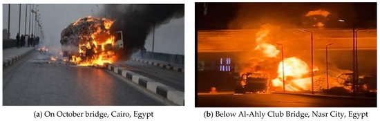
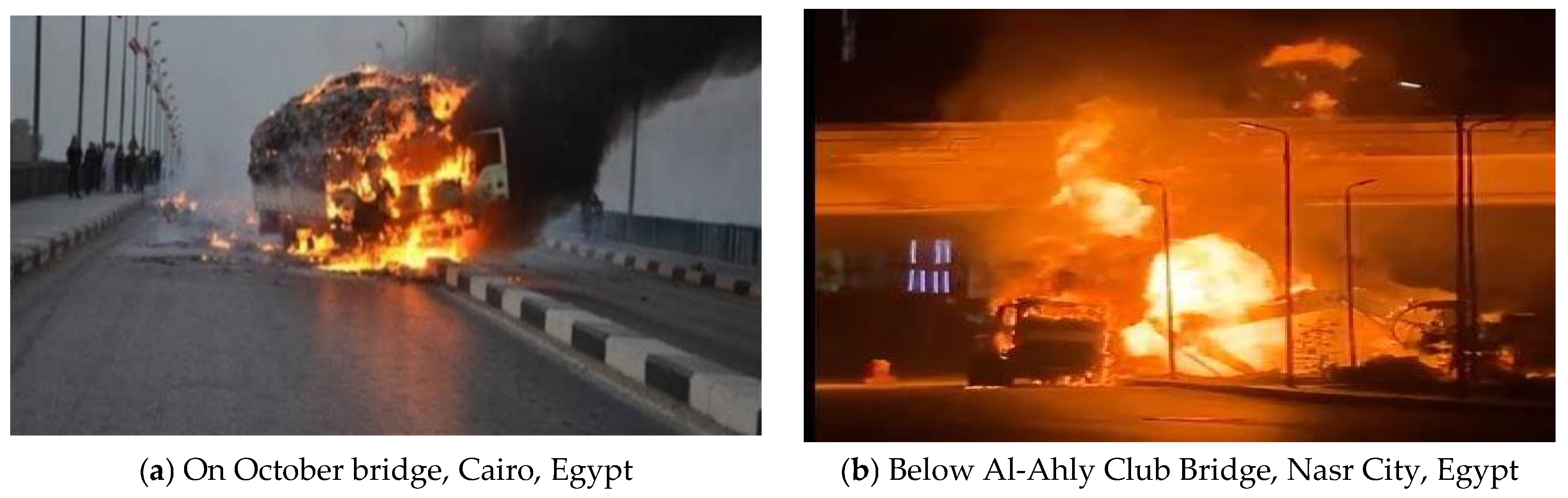
Despite the well-documented risks of fire in buildings and tunnels [13,14], current design codes and standards (CEN, AASHTO, NFPA, and Chinese codes) offer limited provisions for fire resistance design or post-fire evaluation of bridges [15,16,17,18]. This regulatory gap leaves transportation agencies with insufficient guidance for fire prevention, rapid assessment, and restoration of service after an incident. Moreover, bridges are often exposed to additional risks from vehicles transporting hazardous or flammable materials. Fires may ignite directly on bridge decks (vehicle collisions or fuel spills) or below bridge spans (ruptured gas pipelines), as illustrated by incidents such as the October Bridge fire in Cairo, Egypt (Figure 1a), and the Al-Ahly Club Bridge fire in Nasr City (Figure 1b).
Figure 1.
Examples of fire accidents.
The extent of fire damage in bridges depends on several factors, including fire type, intensity, exposure duration, and structural system characteristics [15,19,20]. Due to their low thermal conductivity and high thermal mass, concrete bridges generally exhibit better inherent fire resistance than steel bridges, as heat penetration into internal reinforcement occurs more slowly. However, severe fire exposure may still result in concrete spalling, cover loss, reinforcement exposure, cracking, and stiffness degradation, which can adversely affect structural safety, serviceability, and long-term durability. The severity of these effects is influenced by material properties, fire intensity, and structural configuration.
Concrete bridges constitute the vast majority of bridge infrastructure worldwide. China’s highway network currently includes approximately 800,000 bridges; however, steel bridges, including steel–concrete composite types, account for less than 0.3% of the total number [21]. This relatively low proportion reflects the higher maintenance demands, increased life-cycle costs, and specialized construction requirements associated with steel bridges. Although concrete bridges rarely experience complete collapse following fire exposure, varying levels of material and structural degradation may occur [22]. Therefore, comprehensive post-fire assessment is essential, including detailed inspection, material testing, and structural evaluation, to determine residual load-carrying capacity, quantify damage severity, and define appropriate repair and rehabilitation measures to ensure the safe restoration of structural performance and serviceability [8].
In recent years, several studies have examined the impact of fire on concrete bridge performance. Lee et al. [23] analyzed bridge failures by cause and reported that 3.2% of bridge failures were due to fire, compared to 1.8% and 2.1% caused by wind and earthquake, respectively. They noted that, unlike wind and earthquake loading, the behavior of bridge structures under fire exposure is still not fully understood. Moreover, because fire scenarios vary significantly in terms of heat release rate, ventilation conditions, and structural design parameters, fire safety procedures developed for buildings are not directly applicable to bridge infrastructure [9].
Experimental studies have also provided important insights. Luo et al. [24] constructed ten prestressed concrete hollow slab girders (13 m span) to evaluate post-fire behavior through controlled fire simulations and static load testing. Their findings showed that the peak temperature of the prestressing tendons was the primary factor influencing the residual bearing capacity, with strength decreasing as tendon temperature increased. Similarly, Davis et al. [25] investigated damage caused by a tanker fire on a precast, prestressed concrete bridge and documented the need for rapid condition assessment after such incidents. On a broader scale, Giuliani et al. [26] studied the incidence and consequences of bridge fires, highlighting the importance of structural vulnerability factors as well as the economic and social impacts. Although they did not propose a formal fire risk assessment method, they strongly advocated for the development of fire safety design provisions for bridges. Complementary to this work, Joo et al. [27] developed a field-survey-based approach to evaluate bridge fire risk. Their study, conducted on the Korean bridge network, found that cable-stayed and suspension bridges primarily sustained fire damage on their deck surfaces, while damage to substructures was minimal. Because special bridges account for only about 1% of all Korean bridges, their evaluation focused mainly on conventional bridge types.
Finally, X. Liu et al. [8] conducted a comprehensive case study combining parametric finite element analysis, field inspection, material testing, and load testing of a fire-exposed prestressed concrete box girder bridge. They reported that fire had only a minor effect on the bridge’s dynamic characteristics, as the measured fundamental frequency of the fire-exposed span was approximately 97% of the original and theoretical values. Based on their findings, targeted repair measures were recommended and implemented, and subsequent field loading tests confirmed the effectiveness of the rehabilitation strategy.
In most post-fire bridge research, the assessment of fire effects on structural strength has relied on either experimental field testing of fire-damaged bridges or theoretical predictions obtained through finite element (FE) analysis [2,28,29]. However, one major limitation of both approaches is the inability to accurately capture the bridge’s true pre-fire structural condition. Typically, the theoretical structural performance is estimated using the original design parameters and assumed to represent the bridge’s pre-fire capacity. In practice, the actual performance is often lower than the theoretical prediction due to material aging, traffic-induced fatigue, environmental deterioration, and other degradation mechanisms. This discrepancy may lead to an underestimation or overestimation of the actual impact of fire damage.
Several researchers have investigated the behavior of bridge components under fire loading through small-scale experiments and FE modeling [30,31,32,33,34]. However, few studies have conducted post-fire evaluations of full-scale concrete box girder bridges, largely because such tests are logistically challenging and costly. Furthermore, small-scale specimens may experience more severe thermal gradients and higher peak temperatures compared to full-size elements, which can exaggerate damage severity and reduce the reliability of extrapolating results to real structures [35]. To address these limitations, the present study provides a comprehensive case study of the Delta Bridge, a full-scale concrete box girder bridge located along the Maria Axis, west of Alexandria, Egypt. The research includes detailed inspection, material testing, and field load testing of two spans exposed to fire. A combination of visual inspection, photographic documentation, and hammer sounding was used to evaluate surface damage, while concrete cores and reinforcing steel bar samples were extracted and tested in the laboratory to determine residual compressive and tensile strength. In addition, temperatures at various depths were estimated to better understand the thermal exposure profile. The findings of this study offer valuable insights for post-fire structural performance assessment, enabling engineers to develop targeted repair and strengthening strategies for similar concrete box girder bridges.
2. Bridge Description
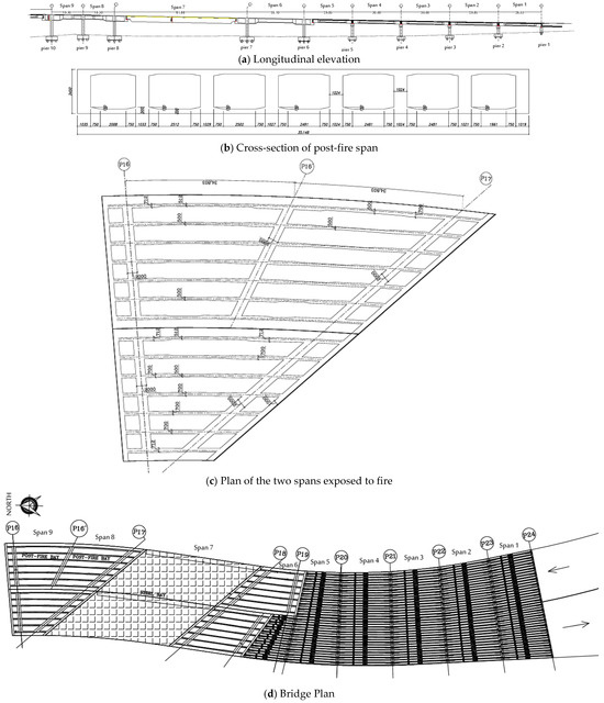
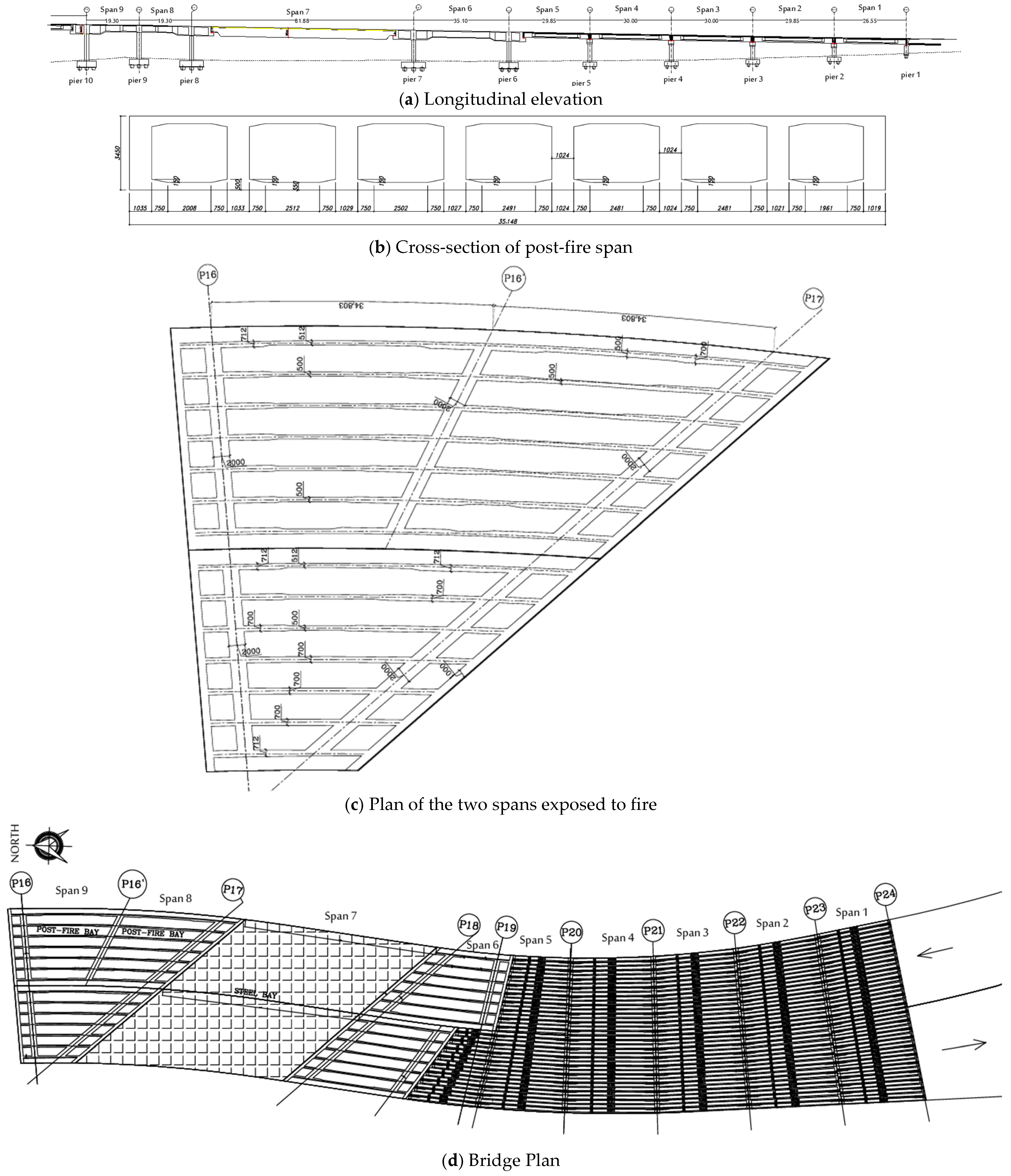
The Delta Bridge, illustrated in Figure 2, is one of the major elevated transportation structures along the Maria Corridor in Egypt. The construction of the bridge commenced on 30 June 2023 and was fully completed on 30 October 2025, after which it was opened to traffic under full design loading conditions. The bridge is strategically located (west of Alexandria, Egypt) and serves as a critical transportation link connecting the Cairo–Alexandria Desert Road to the south with the International Coastal Road to the north. Functionally, the bridge plays a vital role in facilitating the movement of vehicles and freight traffic across the New Delta Canal, a major national water conveyance project designed to transport irrigation water to the western desert region for the reclamation and cultivation of millions of feddans. Owing to its strategic location and infrastructural importance, the Delta Bridge represents a key component of the Maria transportation axis.
Figure 2.
Dimensions, layout, and details of the Delta bridge.
Structurally, the bridge comprises twenty-five simply supported spans with a total length of approximately 1100 m. The superstructure consists of eighteen precast concrete beam girder spans, two steel girder spans, and five reinforced concrete box girder spans. The bridge deck accommodates two traffic directions with an overall width of 54 m. A typical cross-section of the left carriageway is presented in Figure 2b, while the general plan layout of the bridge is shown in Figure 2d. During the construction phase, the bridge was exposed to a fire incident that occurred while dismantling the timber formwork of box girder spans No. 8 and 9. This event necessitated a detailed structural assessment and subsequent rehabilitation measures, which form the primary focus of the present study.
On Wednesday, 24 January 2024, at approximately 11:00 a.m., during the removal process of the timber formwork used for casting the bottom slab of the box girder, a fire erupted in the timber formwork associated with spans 8 and 9, which belong to the concrete box-girder section of the Delta Bridge. The fire persisted for nearly two hours before being extinguished around 1:00 p.m. by firefighters using water. According to the post-incident investigation, the fire originated in the northbound direction and spread rapidly along the two spans due to strong wind conditions. The affected spans are elevated approximately 9 m above ground level, allowing significant airflow that likely intensified the fire. At the time of the incident, the columns had already been cast and had attained sufficient hardened strength and were not part of the temporary timber formwork system; however, they were subjected to elevated temperatures during the fire event, particularly in the upper portions of the columns.
The combustible material was limited to the timber formwork system (20 mm plywood supported by 10 × 15 cm timber joists), while the supporting jacks were steel. The equivalent wood mass is estimated at approximately 30–40 kg/m2, corresponding to a fire load of about 500–700 MJ/m2. Fire spread was likely intensified by wind activity during daytime conditions.
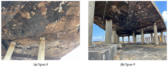
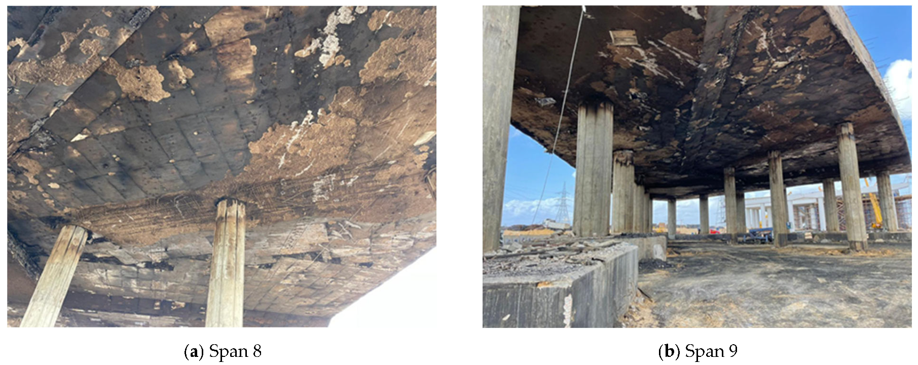
As shown in Figure 3, the incident caused varying degrees of damage to the bridge’s bottom slabs, webs, columns, and bearings. The black rectangular areas in Figure 3a correspond to charring and soot marks caused by the combustion of plywood formwork that was directly in contact with the concrete surface. No intact plywood residues remained after the fire, only combustion-induced surface marks. The following day, at 10:00 a.m., engineers from Saad International Consulting performed a detailed on-site inspection. Their preliminary evaluation concluded that the bridge sustained moderate fire damage but remained standing. Nevertheless, there was concern that the residual structural capacity and serviceability of the affected spans may have been compromised, prompting further material testing and field load evaluation.
Figure 3.
Post-fire condition of the Delta Bridge, showing severe charring, concrete spalling, discoloration, and exposure of columns and soffit surfaces beneath the box girder spans.
3. Comprehensive Assessment of Structural Condition After Fire Exposure
3.1. Inspection
A comprehensive post-fire inspection of the Delta Bridge was carried out by Saad International Consulting Engineers. The investigation included a systematic visual and photographic survey of the slabs, webs, and columns of all spans, with special focus on the fire-affected regions. To assess surface integrity, hammer sounding was performed on fire-exposed areas to detect concrete delamination. In locations showing visible deterioration, the damaged concrete cover was carefully removed using an electric drill to expose the underlying reinforcement and evaluate the condition of the interior concrete.
The inspection documented concrete spalling, loss of cover, cracking patterns, and discoloration. The most severe damage was concentrated in spans 8 and 9, as illustrated in Figure 3a,b. Fire-induced effects on these spans included extensive surface charring, localized spalling of the soffit concrete, and soot deposition. In contrast, the footings at piers 8, 9, and 10 exhibited only minor surface damage, characterized by map cracking, light pink discoloration, and soot deposits on the front walls. Importantly, no concrete spalling was observed in the footing components, indicating that the fire’s thermal intensity was more critical in the superstructure than in the substructure.
3.2. Materials Testing
Bridge structural performance after fire exposure depends primarily on the residual strength of critical elements such as concrete and reinforcing steel. To accurately assess these properties, the laboratory of the faculty of engineering at Alexandria University (Alexandria, Egypt) conducted a comprehensive material evaluation. Concrete cores and reinforcing bar samples were extracted from the most severely damaged sections of the bridge to enable precise strength testing.
Table 1 presents the reduction coefficients for post-fire concrete compressive strength at various surface temperatures, as specified in EN 1992-1-2 [36]. These coefficients apply specifically to the water-cooling method. However, due to the complex and variable nature of real fire scenarios, these theoretical reduction factors may not always reflect the actual residual strength of fire-damaged concrete. Consequently, both laboratory core compressive tests to determine the concrete’s post-fire strength. To minimize the effects of surface spalling and cracking, the cores were extracted from a depth greater than 5 cm below the exposed concrete surface.
Table 1.
Reduction coefficients for the compressive strength of post-fire concrete subjected to water cooling (EN 1992-1-2).
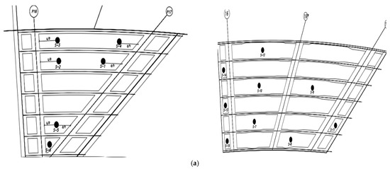
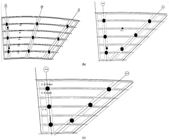
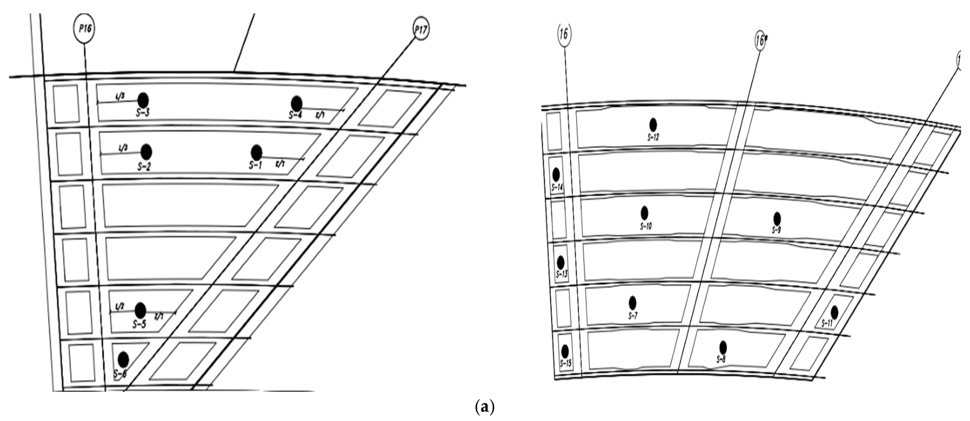
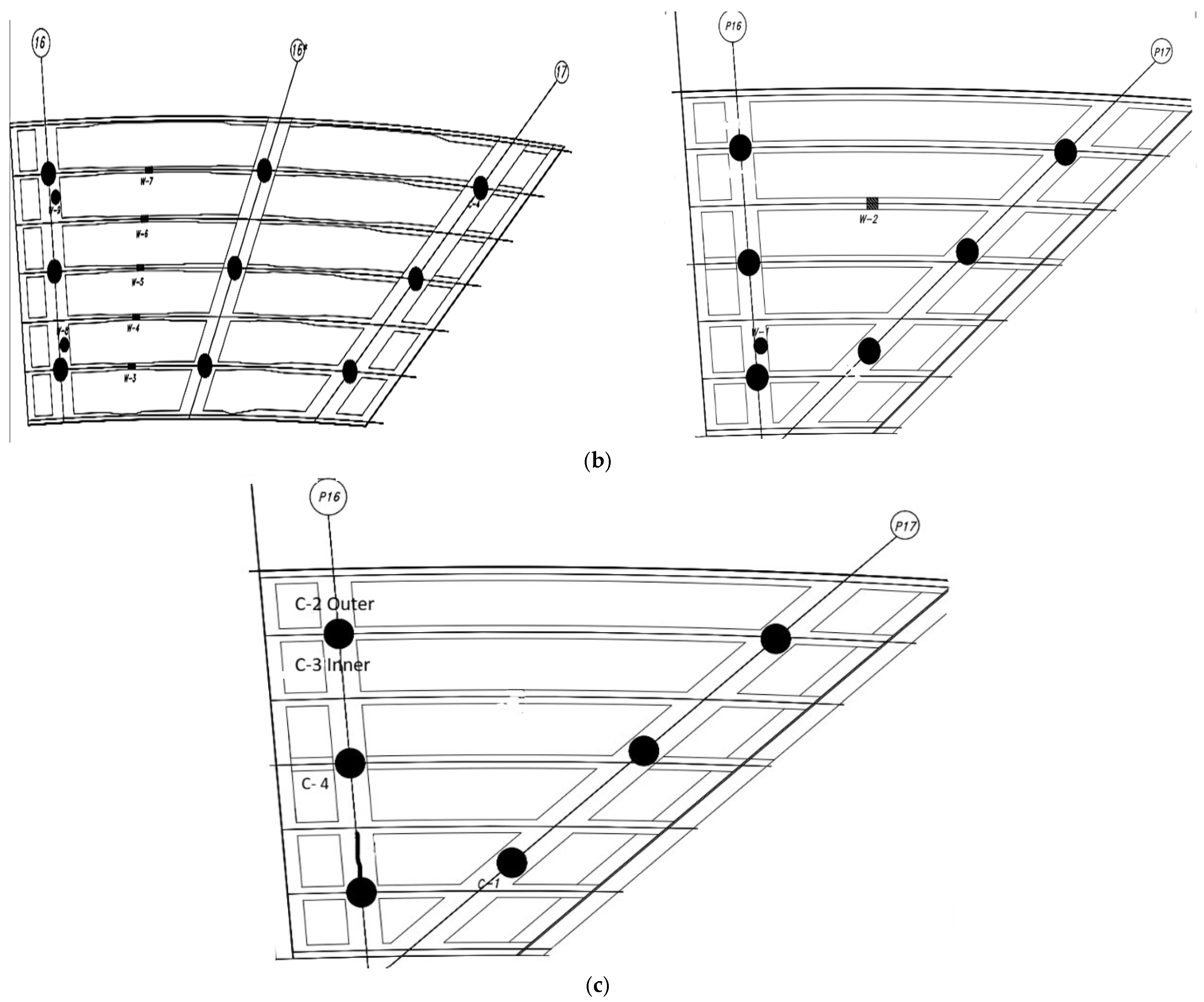
In accordance with the Egyptian Code of Practice (ECP 203) [37], a total of 28 cylindrical core samples, each with a diameter of 9.40 cm, were extracted using a core drilling machine. The sampling program included 15 vertical cores from the bottom slab, 9 horizontal cores from the web of the box girder, and 3 horizontal cores from the columns. These specimens were prepared and tested to evaluate the residual compressive strength of the structural elements within the two spans affected by the fire. Column cores were extracted from the upper portion of the columns, approximately 15 cm below the bottom slab level, representing the zone most likely to be affected by fire exposure. Bottom slab and web cores were extracted from the external web surfaces within the fire-affected spans, not from the interior of the box. Although cores were primarily extracted from fire-affected zones to directly evaluate residual material performance in the damaged areas, the measured compressive strengths were systematically compared with documented construction-phase strength records, in addition to verifying compliance with the acceptance limits specified in ECP 203 [37]. We acknowledge that extracting additional reference cores from non-fire-exposed regions could provide further calibration of post-fire strength measurements. However, the availability of reliable baseline construction data enabled a technically consistent comparison for assessing residual concrete performance. The exact locations of the core extractions from the columns, webs, and bottom slab are illustrated in Figure 4. The original in situ concrete compressive strength recorded during construction was 53 MPa for the bottom slab, 58.5 MPa for the webs, and 49.2 MPa for the columns. The measured compressive strengths of the extracted core samples for each structural member are summarized in Table 2.
Figure 4.
Locations of concrete core samples extracted from the structural elements of the fire-exposed spans: (a) Slab samples, bottom slabs, (b) Web samples, webs of the box girder, and (c) Column samples, columns.
Table 2.
Compressive strength of bridge members after fire exposure.
To accurately reflect the spatial heterogeneity induced by fire exposure, the statistical evaluation of compressive strength was conducted separately for each structural component rather than relying on global averages. For the bottom slab (15 cores), the mean cube compressive strength (fcu) was 48.47 MPa with a standard deviation (SD) of 8.23 MPa and a coefficient of variation (COV) of 16.98%, indicating moderate dispersion consistent with direct flame impingement and non-uniform thermal penetration through the slab thickness. In contrast, the webs (9 cores) exhibited a higher mean strength of 53.89 MPa with a lower standard deviation of 5.83 MPa (COV = 10.81%), suggesting comparatively more uniform thermal exposure likely due to geometric configuration and partial shielding effects. The columns (4 cores) showed a mean compressive strength of 43.88 MPa with a standard deviation of 5.48 MPa (COV = 12.49%); despite the limited sample size, the variability remained within acceptable limits and did not indicate abnormal localized deterioration. Across all components, the calculated coefficients of variation (10–17%) demonstrate controlled and mechanically consistent variability typical of thermally affected reinforced concrete.
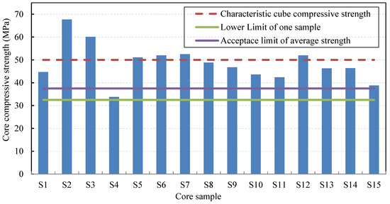
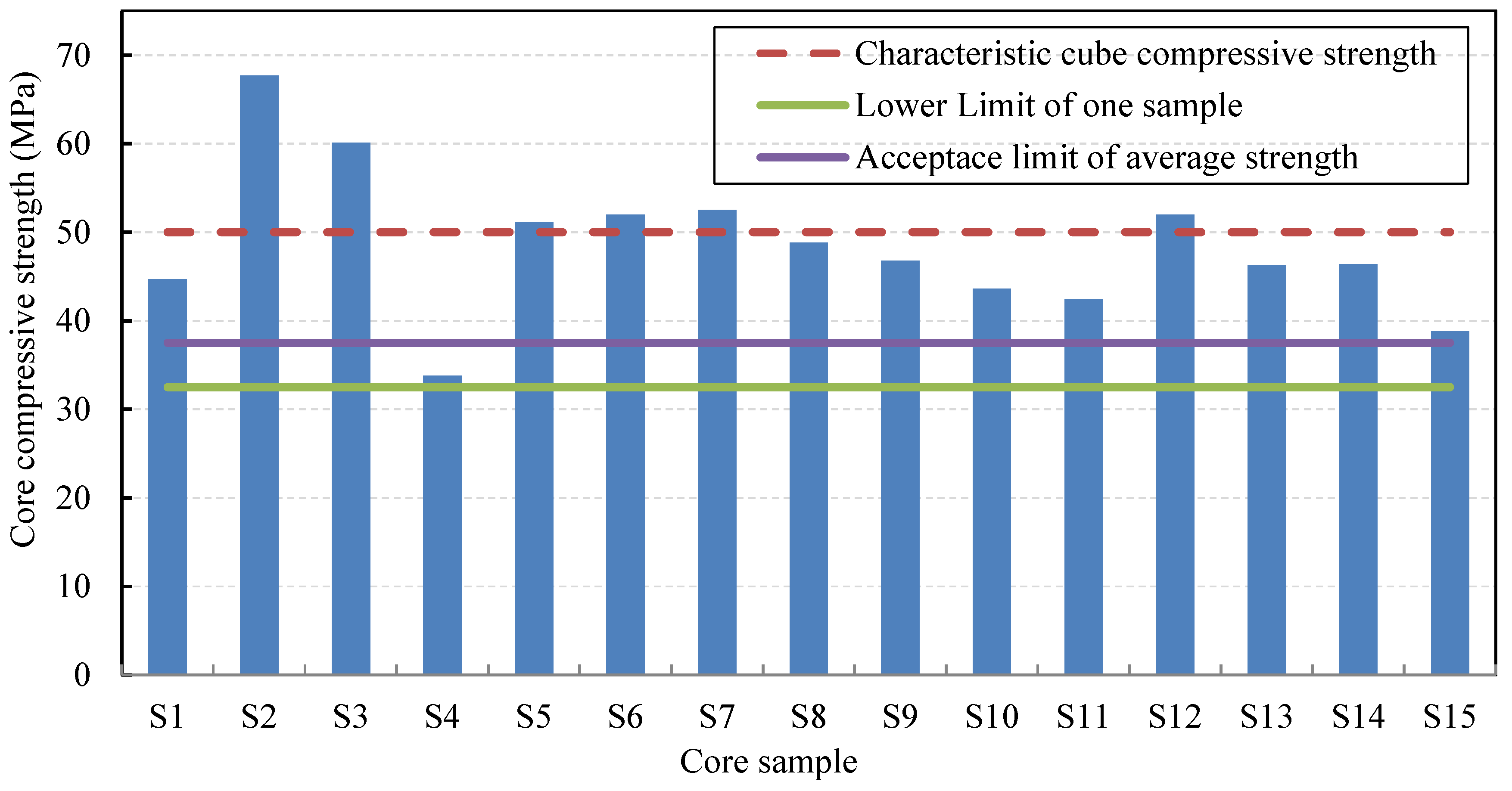
Figure 5 presents the compressive strength results of the bottom slab cores, where the measured strength of each core specimen is plotted individually. As shown in Figure 5 and Table 2, the mean equivalent cube compressive strength of the slab cores was 48.50 MPa. Among the specimens, S2 and S3 exhibited the highest strengths at 67.70 MPa and 60.10 MPa, respectively, while the lowest strength was recorded for sample S11 at 32.60 MPa. Table 3 summarizes the acceptance criteria for concrete core test results according to ECP 203 [37]. Per these provisions, the concrete is considered acceptable if (a) the estimated average cube strength from at least three cores is more than 75% of the specified strength and (b) the strength of any individual core is more than 65% of the specified strength.
Figure 5.
The post-fire compressive strength results of the bottom slab cores.
Table 3.
Acceptance limits of concrete core test according to ECP 203 [37].
Although the standard deviation of the slab core strength results is relatively high (≈8.23 MPa), this does not indicate different concrete production batches. The bottom slab concrete was originally cast using the same concrete mix design and production process during construction, as confirmed by the recorded in situ construction strength data.
The observed variability in post-fire core strength is primarily attributed to the non-uniform thermal exposure during the fire event, including variations in flame contact, temperature gradients through the slab thickness, and localized cooling effects during fire suppression. Such variability is commonly reported in post-fire concrete assessments and reflects heterogeneous thermal damage rather than differences in original concrete quality.
Based on the results in Figure 5 and Table 3, the post-fire compressive strength of the bottom slab satisfies the acceptance criteria. The average compressive strength of the lower slab after fire exposure showed a reduction of approximately 8.5% compared to the original in situ concrete strength recorded during construction. Nevertheless, the measured value of 48.50 MPa still exceeds the minimum required average strength of 37.50 MPa specified by ECP 203 [37] by 29.24%. Furthermore, all individual core strengths are greater than the minimum required value of 32.50 MPa. These findings confirm that the residual concrete strength of the bottom slab remains structurally adequate after the fire exposure.
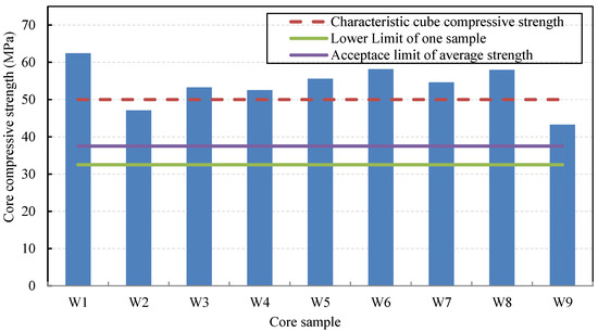
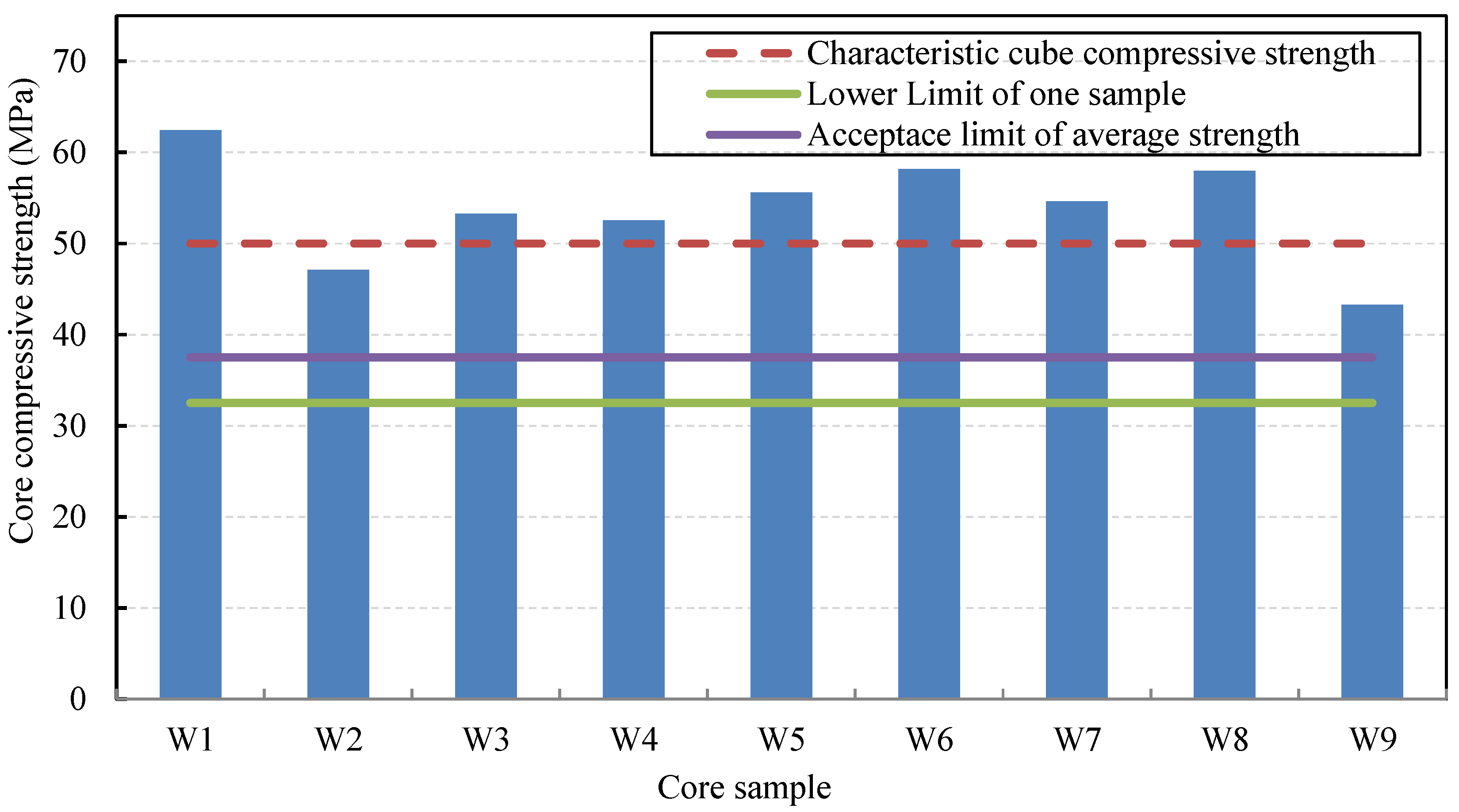
Figure 6 presents the post-fire compressive strength results of the web cores. Sample W1 exhibited the highest strength at 62.50 MPa, representing a 24.9% increase relative to the Characteristic cube compressive strength of the concrete web. This was followed in descending order by samples W6, W8, W7, W5, W3, and W4. Conversely, samples W2 and W9 recorded the lowest strengths at 47.10 MPa and 43.30 MPa, respectively. The average compressive strength of all cores extracted from the webs of the fire-exposed spans showed a reduction of approximately 7.9% compared to the original in situ concrete strength recorded during construction. Nevertheless, the measured average value of 53.90 MPa still exceeds the minimum requirement specified by the Egyptian Code (ECP 203) [37]. Moreover, Table 3 and Figure 6 confirm that every individual sample meets the minimum acceptance criterion for a single core. These results collectively indicate that the post-fire compressive strength of the webs satisfies the acceptance requirements stipulated in ECP 203 [37].
Figure 6.
The post-fire compressive strength results of the web cores.
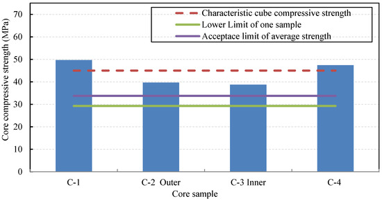
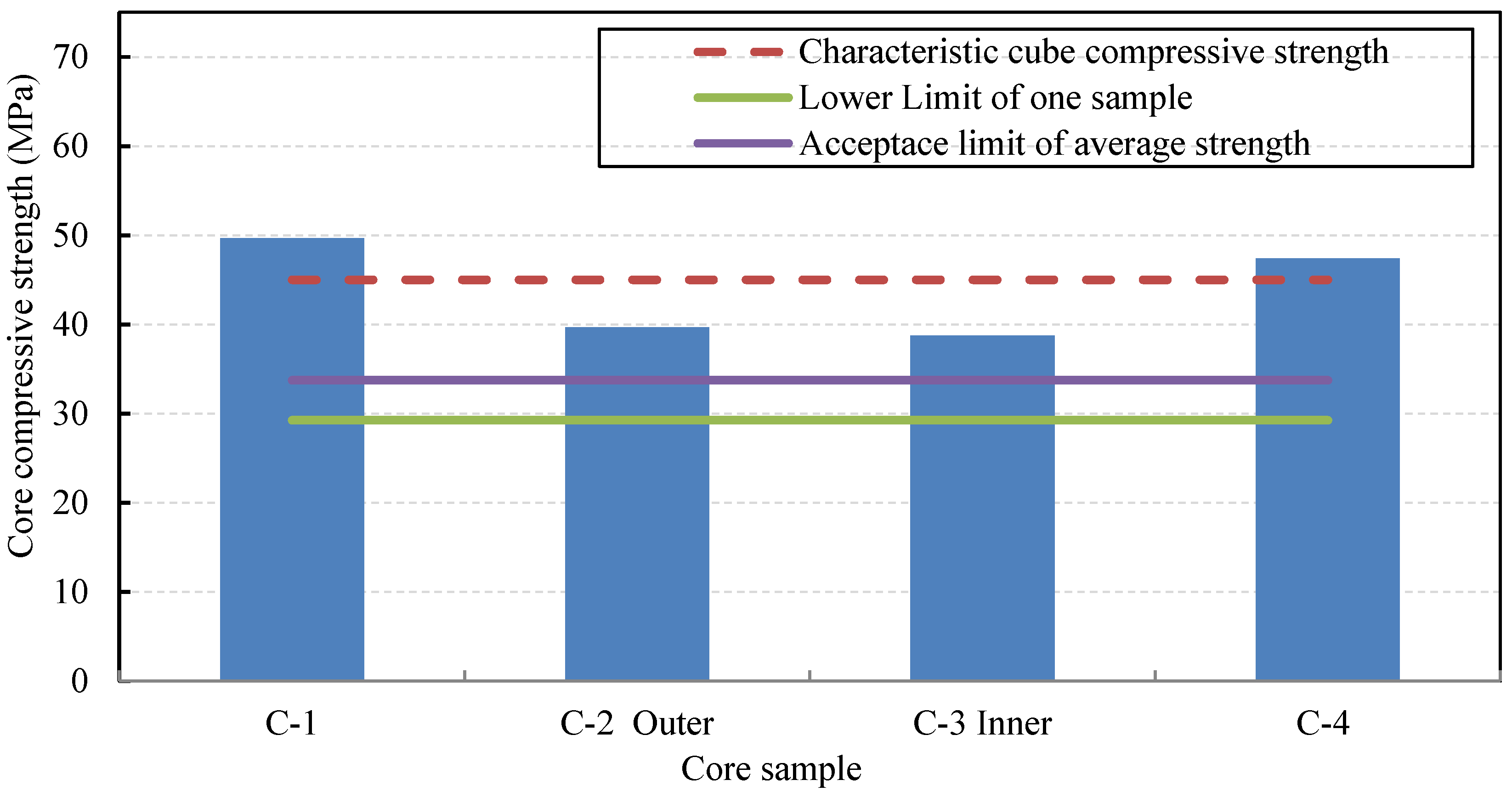
Figure 7 presents the compressive strength results of core samples extracted from the post-fire columns. It is evident that the compressive strengths of samples C1 and C4 increased by 10.40% and 5.40%, respectively, relative to the column Characteristic cube compressive strength of 45 MPa. Conversely, the compressive strengths of the C-2 Outer and C-3 Inner samples decreased by 11.80% and 13.90%, respectively. The average compressive strength of the cores extracted from the fire-exposed columns was 43.88 MPa. This value represents a reduction of approximately 10.8% compared to the original in situ concrete strength recorded during construction. However, it still exceeds the minimum required strength specified by ECP 203 [37] by approximately 30%, Despite these reductions, all tested samples satisfy the minimum acceptance criteria stipulated by ECP 203 [37], confirming that the concrete in the columns of the two fire-exposed spans remains structurally acceptable.
Figure 7.
The compressive strength results of core samples extracted from the post-fire columns.
Conversely, in accordance with the China Association for Engineering Construction Standardization (CECS 252) [38], Table 4 presents the reduction coefficients for the tensile strength of reinforcement steel bars at various temperatures. Following the recommended evaluation procedure, three upper reinforcement bars with diameters of 12 mm, 16 mm, and 18 mm, as well as three lower reinforcement segments with diameters of 16 mm and 18 mm, were extracted and tested to determine their post-fire tensile strength. The measured tensile strength results of the selected steel bars are summarized in Table 5.
Table 4.
Reduction coefficient of the post-fire reinforcement steel bar’s tensile strength (CECS 252).
Table 5.
The measured tensile strength results of the selected steel bars after fire exposure.
The post-fire tensile test results showed that the minimum residual yield strengths of the 12 mm, 16 mm, and 18 mm reinforcement bars were 445 MPa, 490 MPa, and 506 MPa, respectively, compared with the original in situ minimum yield strengths of 510 MPa, 555 MPa, and 570 MPa recorded during construction. These values correspond to moderate strength reductions of approximately 12.7%, 11.7%, and 11.2%, respectively, with an average reduction coefficient of about 0.87. It should be emphasized that this reduction coefficient was not used to deterministically back-calculate the exact fire temperature. Instead, it was adopted as an indicative parameter to qualitatively assess the severity of thermal exposure. The obtained value (≈0.87) is consistent with the reduction range reported around 600 °C in CECS 252, providing a reasonable estimate of the probable peak temperature experienced by the reinforcement. A similar interpretative methodology has been adopted in previous post-fire assessment studies [8]. Most importantly, the structural safety evaluation was based on direct tensile testing results and full-scale load testing, rather than on inverse statistical inference from code-based temperature–reduction tables. All tested bars satisfied the minimum yield strength requirements specified by ECP 203 [37], confirming the structural adequacy of the reinforcement after fire exposure.
In the investigated bridge, the concrete cover thickness was uniformly designed and executed as 25 mm for all fire-exposed structural elements (slabs, beams, and Columns in accordance with the ECP 203 [37]. Therefore, no variation in cover thickness existed among the affected members that could lead to differential thermal exposure of reinforcement. Moreover, the fire suppression process was carried out simultaneously using water cooling for all affected spans. Since the same extinguishing method and timing were applied across the exposed elements, the thermal shock and cooling effects can be considered consistent throughout the investigated region. Most importantly, the evaluation of reinforcement residual performance was primarily based on direct tensile testing of extracted steel samples rather than solely relying on code-based reduction factors.
3.3. Estimation of Elevated Temperatures in Fire-Exposed Bridge Members
The residual load-carrying capacity of fire-damaged bridges is influenced by several factors, including the nature and duration of the fire, the method of fire suppression, and the extent and severity of damage sustained by the structural components. Accurate estimation of a bridge’s residual strength after fire exposure requires an evaluation of the thermal distribution and peak temperatures experienced by its spans and structural members. Surface temperature estimation can typically be inferred from visual indicators such as changes in concrete color, the degree of observed damage, and the response to hammer-sounding tests. Thermal conduction principles may also be applied, taking into account the fire scenario, extent of damage, and material properties of the bridge elements [3].
The field observations revealed that the concrete surfaces in the fire-affected zones exhibited characteristic color changes: the columns displayed a white-gray appearance, while the webs and slabs exhibited a light pink hue. These regions also showed clear signs of fire damage, including spalling, cracking, loss of cover, and brittle, friable concrete when subjected to hammer impact testing. It is acknowledged that EN 1992-1-2 [36] and CECS 252 [38] provide different temperature-dependent reduction coefficients due to differences in calibration basis and intended application. However, the temperature values presented in Table 6 do not represent a direct numerical adoption of reduction coefficients from either code. In the present study, CECS 252 [38] was referenced for general guidance on temperature-dependent material behavior, while the reported temperature ranges were conservatively estimated based on observed damage patterns and measured material properties. As clarified in the revised manuscript, Table 6 serves as a qualitative interpretative framework supporting the residual capacity assessment rather than a deterministic reconstruction of peak fire temperature. A similar interpretative approach has been adopted in previous post-fire assessment studies [8], where estimated temperature ranges were correlated with observed damage and material degradation rather than derived solely from a single code-based reduction model. These indicative temperature ranges were used to interpret (i) the observed surface damage, (ii) the moderate reduction in concrete compressive strength obtained from cores extracted at depths greater than 5 cm, and (iii) the measured reduction in reinforcement yield strength.
Table 6.
Estimated temperatures at various depths.
In particular, the estimated temperature range below 300–450 °C at depths exceeding 5 cm is consistent with the limited reduction observed in core compressive strength, while the higher surface temperatures (≈550–600 °C) support the recorded reinforcement strength reduction and surface spalling. Therefore, Table 6 serves as a qualitative interpretative framework supporting the residual capacity assessment, rather than as a deterministic reconstruction of peak fire temperature.
4. Field Testing
In accordance with the requirements of ECP 203 [37], static load tests were conducted as part of this case study to assess the structural performance of the Delta Bridge following fire exposure. The objective of these tests was to verify whether the bridge exhibited any abnormal deflection behavior, visible cracking, or damage when subjected to the maximum serviceability loads specified by the code. The residual deformations after unloading were confirmed to be less than 15% of the maximum deflection recorded during testing, satisfying the acceptance criteria.
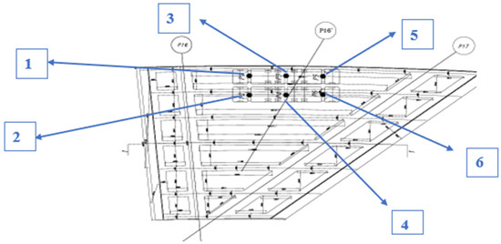
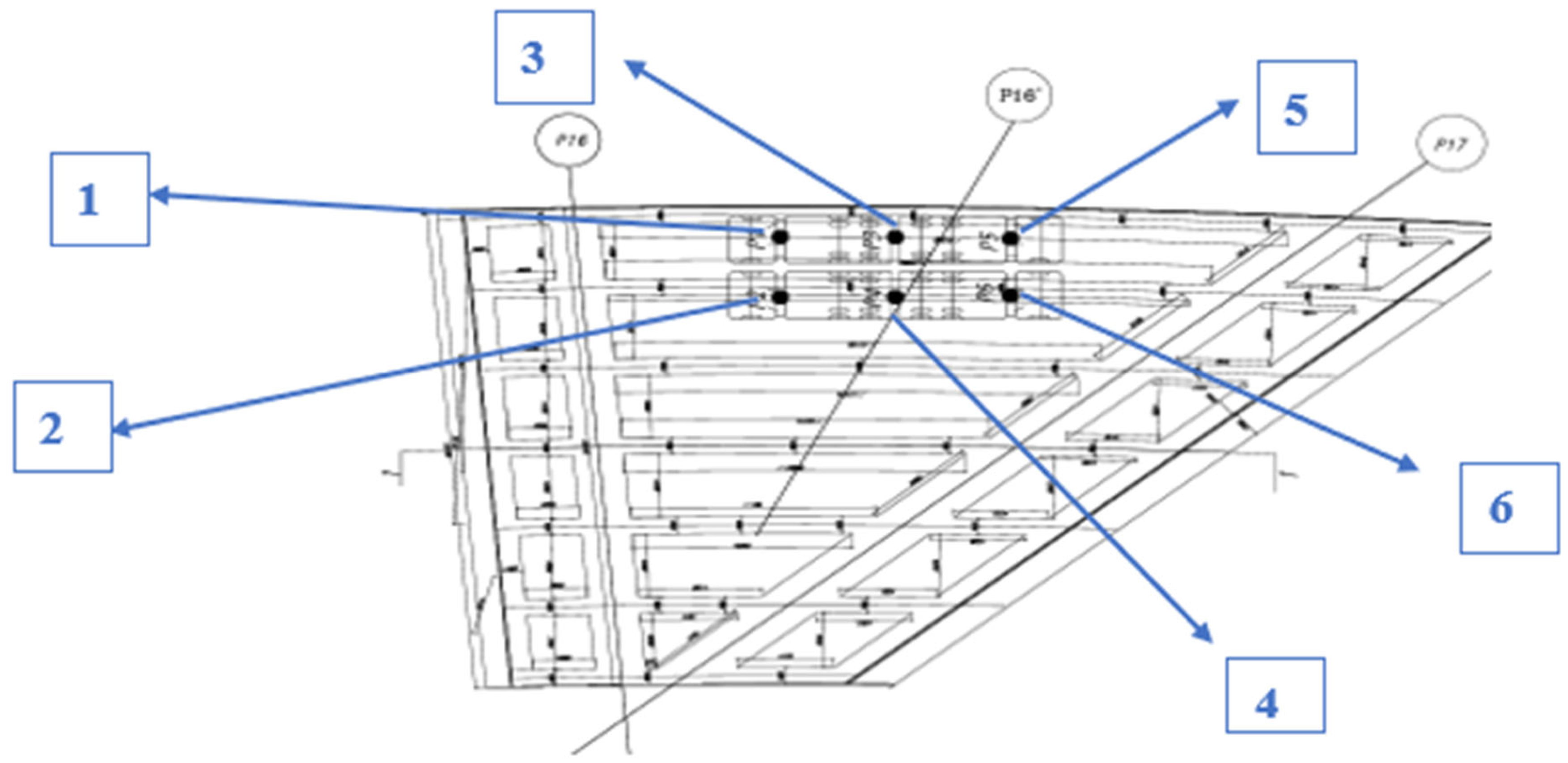
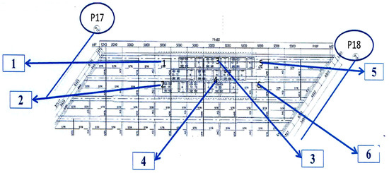
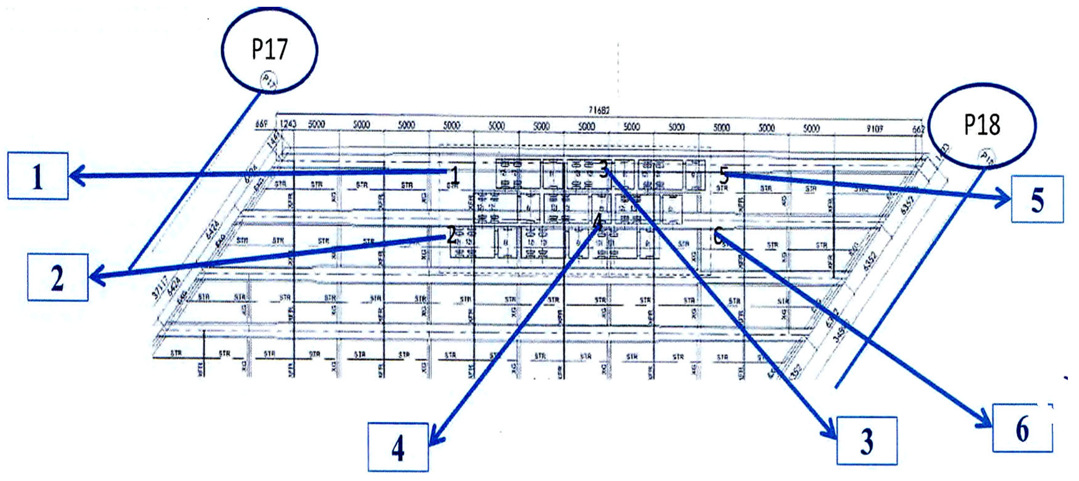
In December 2024, the static load tests were performed by the Concrete Research Laboratory (Cairo University, Cairo, Egypt). The critical mid-span sections were selected for testing, as these locations represent the maximum bending moment regions in simply supported bridge spans under live loading. The post-fire spans located between axes 16 and 17 (spans 8 and 9) were tested using four tri-axle trucks with a gross weight of 40 tons each, as illustrated in Figure 8. In addition, span 7 (between axes 17 and 18) was tested using nine tri-axle trucks, as shown in Figure 9. For each tested span, six measurement points (labeled P1–P6 in Figure 8 and Figure 9) were instrumented to record midspan deflection and micro-strain in the longitudinal reinforcement.
Figure 8.
Loading between axis 16 & 17.
Figure 9.
Loading between axis 17 & 18.
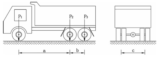
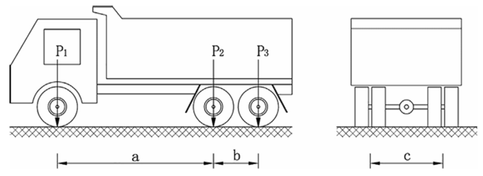
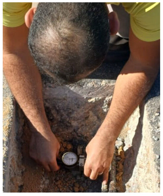
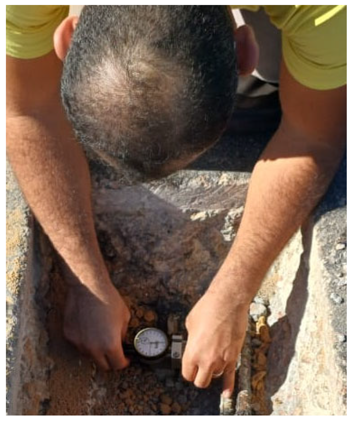
A schematic of the tri-axle truck configuration is presented in Figure 10. The axle spacings a, b, and c measured 4.6 m, 1.4 m, and 1.8 m, respectively, with wheel loads of 80 kN for P1 and 160 kN for P2 and P3. High data quality was ensured throughout the experimental program. Prior to gauge installation, the asphalt and concrete surface were carefully removed and prepared. Electrical resistance strain gauges were then bonded to the top surface of the upper longitudinal reinforcement (see Figure 11). Deflections were measured on the slab surface using precise surveying equipment with an accuracy of 0.1 mm. All sensors and measuring devices were calibrated and verified before testing to ensure reliable data acquisition.
Figure 10.
Schematic of a triaxle truck.
Figure 11.
Installation of strain gauges.
Strain and deflection measurements were recorded at five key intervals: immediately before loading, immediately after loading, one hour after loading, two hours after loading, and immediately following load removal. Table 7 summarizes the experimental results, presenting the measured deflections and micro-strains of the steel reinforcement at the six instrumented locations for both tested spans under the different loading stages and the final unloading condition.
Table 7.
Summary the experimental results (deflections and absolute strain values).
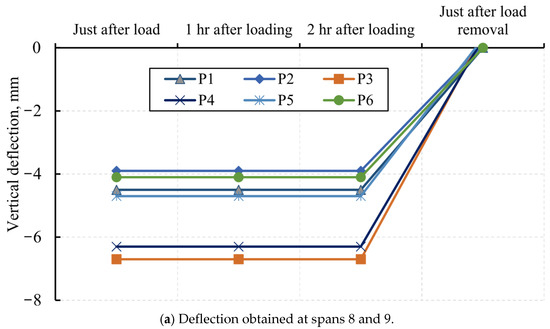
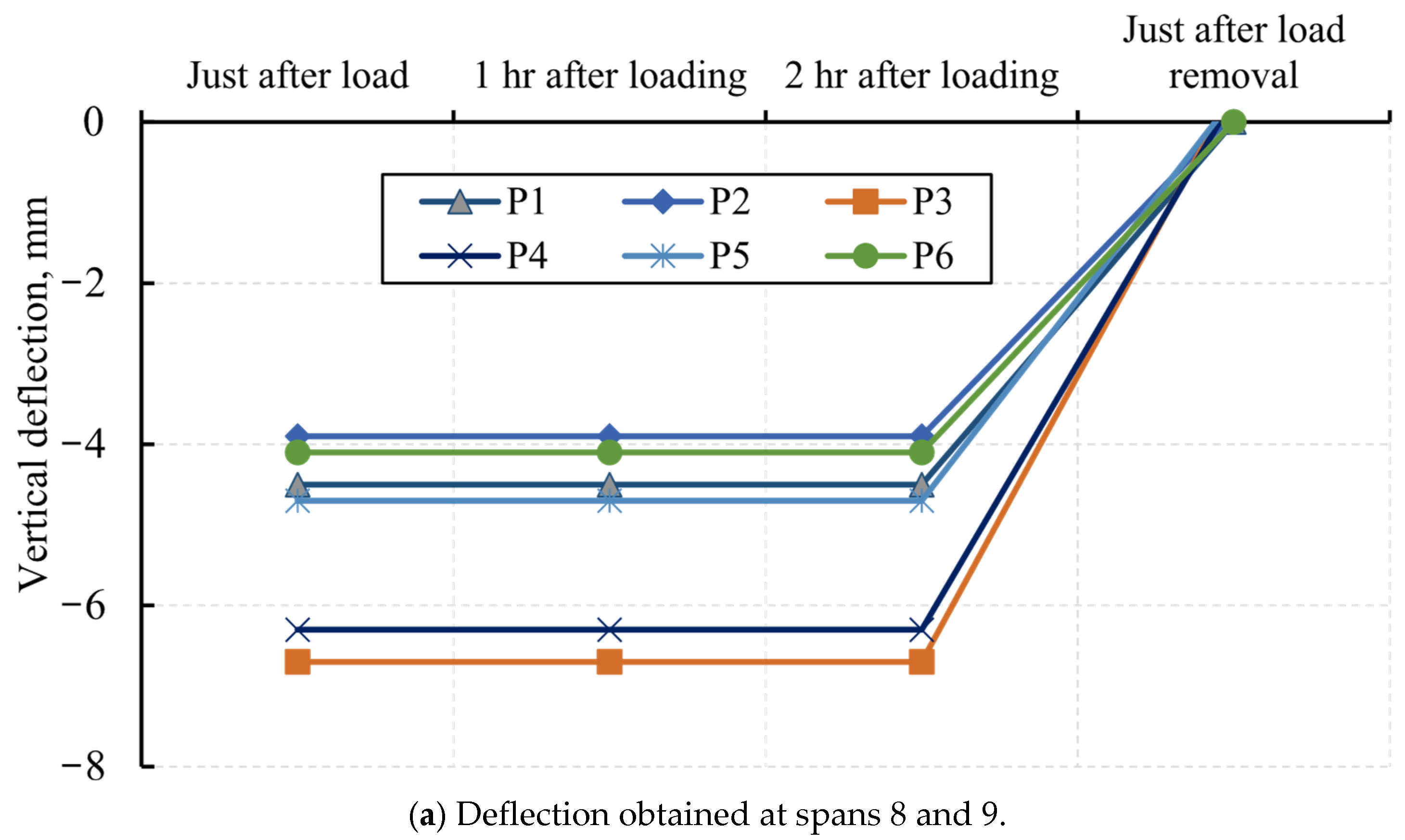
The experimental deflection responses of the post-fire spans during the static loading tests are presented in Figure 12. As shown in Figure 12a,b, the vertical deflections of the loaded spans remained nearly constant under the different loading stages. For instance, the deflection measured at point P1 for spans 8 and 9 was consistently 4.50 mm immediately after loading, one hour after loading, and two hours after loading, indicating minimal time-dependent deformation. Upon load removal, the deflection values approached zero, demonstrating good elastic recovery. At mid-span, the maximum recorded deflections were 6.70 mm at point P3 and 6.30 mm at point P4. The measured deflections at other points were nearly constant across loading stages, with values of 4.50 mm at P1, 3.90 mm at P2, 4.70 mm at P5, and 4.10 mm at P6.
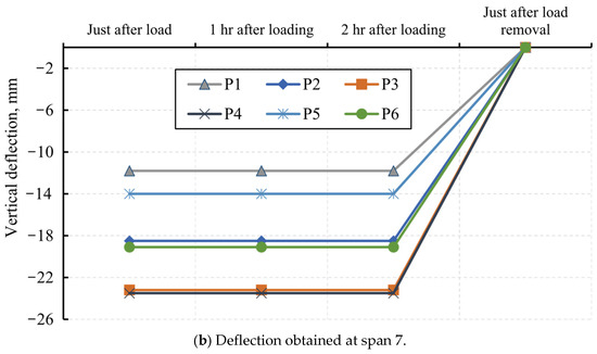
Figure 12.
Experimental deflection during the loading test.
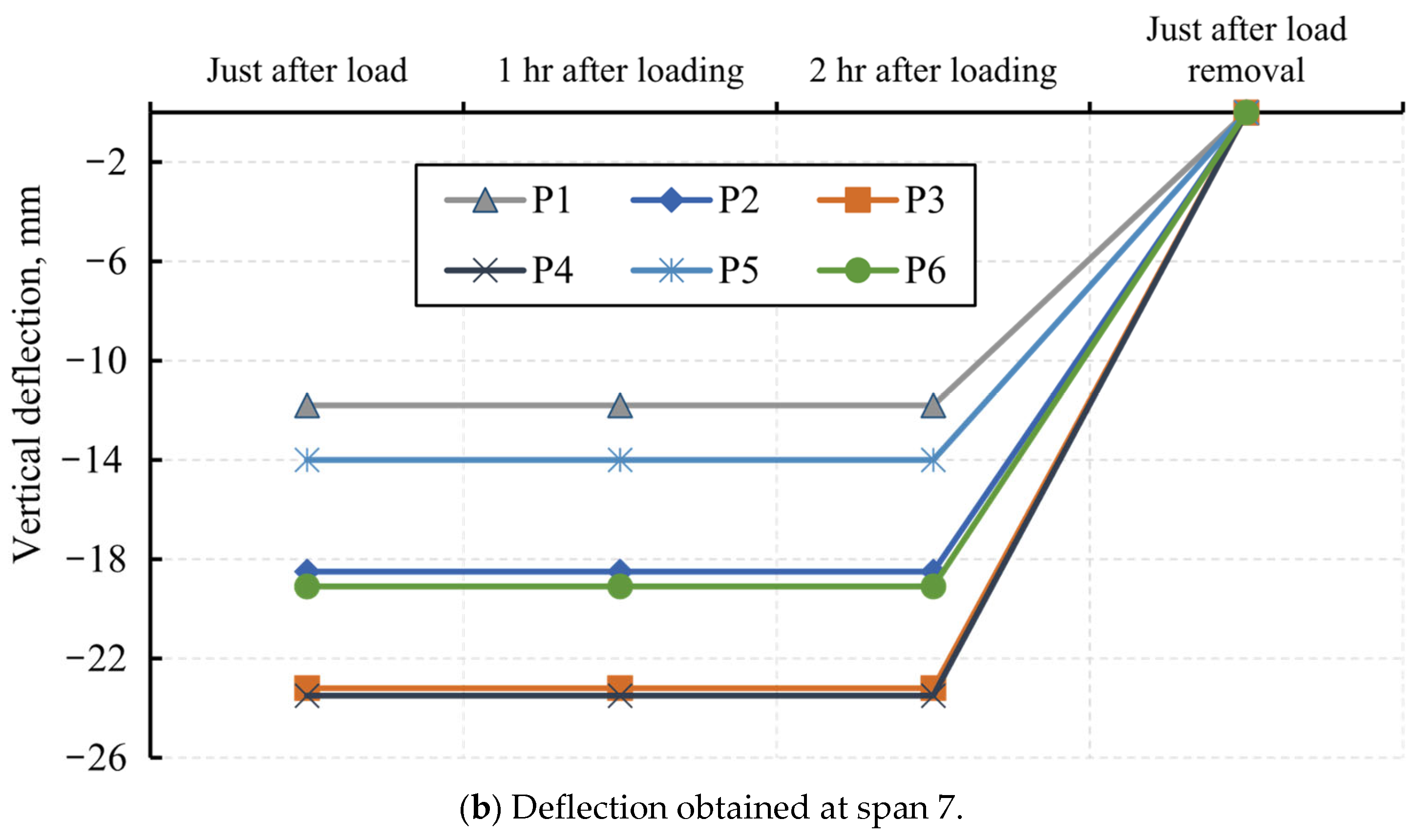
Figure 12b illustrates the deflection profile of composite steel span 7. Similar to spans 8 and 9, the vertical deflection response remained stable across all loading stages. The maximum deflection occurred at mid-span point P4 (23.50 mm), followed by P3 (23.20 mm), P6 (19.10 mm), P2 (18.50 mm), P5 (14.00 mm), and P1, which exhibited the lowest deflection of 11.80 mm. It is evident that the deflections of span 7 are significantly larger than those of spans 8 and 9. This difference is attributed to the structural and geometric characteristics of the spans: span 7 has a considerably longer length (81.88 m) compared to spans 8 and 9 (19.30 m each) and is constructed using steel girders, whereas spans 8 and 9 consist of precast concrete beams.
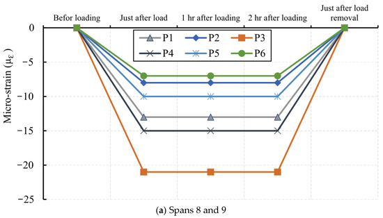
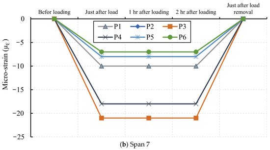
Figure 13 presents the micro-strain measurements of the steel reinforcement in the post-fire top slab during the static loading tests. As illustrated, the micro-strain values at all slab measurement points remained nearly constant throughout the different loading stages (immediately after loading, one hour after loading, and two hours after loading). In contrast, the micro-strain values were close to zero prior to loading and immediately after load removal, indicating full elastic recovery.
Figure 13.
Micro-strain measurements of the steel reinforcement.
Among the measured points, P3—located at mid-span—recorded the highest micro-strain of 21 µε, followed by P4 with 15 µε. The remaining points exhibited micro-strain values of 13 µε at P1, 10 µε at P5, 8 µε at P2, and 7 µε at P6. A similar micro-strain distribution trend was observed for span 7, confirming the consistency of the structural response across the tested spans.
No significant creep or relaxation effects were observed during the static load test.
The measured deflections and micro-strain values remained nearly constant over the 2-h sustained loading period, indicating negligible time-dependent deformation. Furthermore, the nearly full recovery after unloading confirms that the structural response was predominantly elastic under the applied service load.
5. Repair and Rehabilitation of the Delta Bridge
Following the fire incident, a comprehensive experimental assessment program was conducted, including core sampling and compressive strength testing of concrete extracted from columns, slabs, and the box girder soffit, as well as tensile testing of reinforcing steel obtained from critical structural locations, in addition to full-scale static load testing to verify global structural behavior. The results demonstrated that both the residual compressive strength of concrete and the tensile strength of reinforcement remained within the permissible limits specified by the ECP 203 [37]. Furthermore, the static load test confirmed that deflection values, and overall load-bearing performance satisfied the code-required safety and serviceability criteria. Based on these verified quantitative findings, the structural system retained adequate residual load-carrying capacity and safety margins; therefore, advanced strengthening techniques such as CFRP wrapping, hydraulic or steel jacketing, external prestressing, or section enlargement were not technically justified.
Based on the findings necessitated an immediate repair and rehabilitation program aimed at restoring structural capacity, ensuring durability, and prolonging the service life of the bridge.
5.1. Damage Removal and Surface Preparation
In compliance with ACI 562-19 Code Requirements for Assessment, Repair, and Rehabilitation of Existing Concrete Structures [39], all deteriorated materials were systematically removed. The repair process included: (1) cleaning and flushing of affected areas on box slabs, webs, and columns to remove loose debris, contaminants, and surface laitance, (2) chipping and removal of spalled and cracked concrete to a controlled depth ranging between 20 and 80 mm, ensuring exposure of sound substrate, and (3) mechanical sandblasting of exposed reinforcing steel to achieve a near-white metal finish, followed by inspection to verify cross-sectional adequacy.
5.2. Structural Repair and Section Restoration
After proper surface preparation, repair mixtures and strengthening materials were applied. Shotcrete containing high-performance cementitious material was used to restore the removed concrete sections, ensuring proper compaction and bond. Epoxy injection was utilized to seal fine cracks and re-establish continuity in localized areas. Damaged portions of the box girders and columns were reconstructed in compliance with ACI 546R-14 Guide to Concrete Repair [40].
5.3. Surface Protection and Corrosion Mitigation
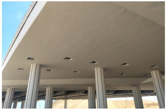
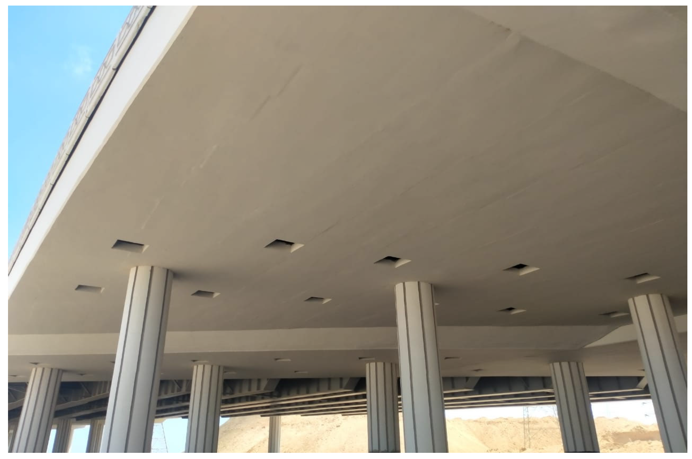
To enhance durability and protect against future environmental and fire exposure, the bottom slab, beams, and columns of the affected spans were coated with a two-component acrylic polyurethane system. This coating provides a protective barrier against chloride ingress, carbonation, and moisture penetration (Figure 14).
Figure 14.
Coating with acrylic polyurethane paint.
5.4. Bearing Replacement
Bridge bearings at piers located on axes 16 and 17 were replaced to re-establish proper load distribution and accommodate thermal and shrinkage movements.
5.5. Post-Repair Evaluation
Following completion of the rehabilitation works, a full-scale field static load test was conducted in accordance with ECP 203 [37] to evaluate the post-repair structural performance. The maximum measured mid-span deflection of the repaired concrete spans (Spans 8 and 9) was 6.7 mm, which is significantly lower than the allowable serviceability limit specified by the code. Deflections remained stable during the 2-h sustained loading period, indicating negligible time-dependent deformation. Upon unloading, recovery ratios ranged between 94% and 100%, confirming predominantly elastic structural behavior with no evidence of residual deformation. The maximum recorded reinforcement micro-strain was approximately 21 µε, which is considerably lower than the steel yield strain, further confirming adequate safety margins. No abnormal cracking, excessive vibration, or distress was observed during testing. Since reopening, the bridge has continued to perform satisfactorily under normal daily traffic, further confirming the effectiveness and reliability of the adopted rehabilitation strategy.
6. Discussion
The comprehensive post-fire assessment of the Delta Bridge provided valuable insights into the structural performance of concrete box girder bridges subjected to severe thermal exposure. The combination of material testing, structural inspection, and full-scale field load testing offered a robust framework for evaluating the residual capacity and effectiveness of subsequent rehabilitation measures.
The results of core compressive strength testing demonstrated that, despite localized concrete spalling and cover loss, the residual average compressive strengths of the bottom slab, webs, and columns exceeded the minimum acceptance limits specified by ECP 203 [37] by 29.2%, 43.7%, and 30.0%, respectively. These findings confirm that the fire did not compromise the overall structural integrity of the concrete elements. Similarly, tensile testing of reinforcing bars revealed an average yield strength reduction coefficient of 0.87, corresponding to an estimated peak temperature of approximately 600 °C, yet still satisfying the minimum yield strength requirement of 500 MPa. These results suggest that the residual material properties were adequate for continued service, provided that damaged cover and spalled areas were properly repaired.
The field static load testing program confirmed that the fire-exposed spans retained a substantial portion of their stiffness and load-carrying capacity. For the post-fire concrete spans (8 and 9), the maximum midspan deflection recorded at point P3 was 6.7 mm. According to ECP 203 [37], the allowable serviceability deflection limit under service loads is L/800. For a span length of 19.30 m, this corresponds to an allowable deflection of approximately 24 mm. Therefore, the measured deflection represents only about 28% of the permissible limit, confirming a substantial safety margin. For the adjacent steel composite span (Span 7), which has a significantly longer length of 81.88 m, the maximum recorded midspan deflection was 23.5 mm. Based on the same serviceability criterion (L/800), the allowable deflection for Span 7 is approximately 102 mm. Accordingly, the measured deflection corresponds to only about 23% of the permissible limit. These results demonstrate that both the fire-exposed concrete spans (8 and 9) and the steel composite span (7) fully satisfy the serviceability requirements specified by ECP 203 [37], with measured deflections remaining well below the allowable limits.
Bridge Design Specifications. Moreover, more than 94% of the recorded deflection was recovered upon unloading, indicating primarily elastic behavior and minimal permanent deformation. The measured micro-strains in longitudinal reinforcement exhibited similar trends, returning to near-zero values after load removal. These results collectively indicate that the bridge maintained adequate stiffness and exhibited no signs of progressive damage or plastic hinging under service loads.
The targeted repair measures—including removal of damaged concrete, derusting of reinforcement, shotcrete application, epoxy crack injection, surface coating, and bearing replacement—were effective in restoring the bridge’s structural performance. The post-repair verification load test demonstrated that the repaired spans satisfied the required strength and serviceability criteria, indicating that the adopted repair methodology mitigated fire-induced deterioration. The application of acrylic polyurethane coating is expected to contribute to improved long-term durability by reducing moisture ingress and mitigating potential future corrosion risk.
This case study highlights the importance of combining field testing with material sampling to accurately assess post-fire residual capacity. Reliance solely on visual inspection could have led to overly conservative decisions, including unnecessary replacement of structural members. The methodology applied here enabled targeted, cost-effective repairs that minimized traffic disruption and preserved the existing bridge superstructure. Furthermore, the results underscore the value of having predefined emergency inspection and testing protocols to expedite decision-making after fire incidents, reducing downtime and economic losses.
7. Conclusions
This study presented a comprehensive post-fire assessment, repair, and validation program for the Delta Bridge, a full-scale concrete box girder bridge exposed to a two-hour fire event. Based on the results of field inspections, laboratory material testing, and full-scale load testing, the following conclusions can be drawn:
- In the Delta Bridge, fire exposure resulted in concrete spalling, cover loss, cracking, and localized reinforcement exposure in spans 8 and 9; however, the damage was confined mainly to surface layers without causing global structural distortion or collapse.
- Post-fire concrete core testing indicated moderate strength reductions relative to the original in situ concrete strength recorded during construction, with average reductions of approximately 8.5% for the bottom slab, 7.9% for the webs, and 10.8% for the columns. Despite these reductions, the residual compressive strengths remained above the minimum acceptance limits specified by ECP 203, confirming the structural adequacy of the fire-exposed concrete elements.
- Post-fire tensile testing of reinforcing bars indicated moderate strength reductions relative to the original in situ yield strength, with reductions of approximately 12.7%, 11.7%, and 11.2% for 12 mm, 16 mm, and 18 mm bars, respectively (average reduction coefficient ≈ 0.87). These results correspond to an estimated peak exposure temperature of approximately 600 °C, yet still meet code-mandated yield strength requirements.
- Static load testing showed stable deflection behavior across all loading stages, with maximum midspan deflections of approximately 6.7 mm and 6.3 mm for the fire-exposed spans (8 and 9), while the longer steel span (span 7) reached a maximum deflection of about 23.5 mm due to its larger span length and different structural system. More than 94% of the deflection was recovered after unloading, indicating predominantly elastic structural behavior.
- Measured reinforcement micro-strain values in the post-fire spans remained low, with a maximum value of approximately 21 µε recorded at midspan, and returned to near-zero levels after unloading, indicating negligible permanent deformation and stable structural behavior under service loading.
- For the Delta Bridge, the implemented repair program—including removal of fire-damaged concrete, reinforcement derusting, shotcrete repair, epoxy crack injection, protective surface coating, and bearing replacement—successfully restored the structural performance of the fire-affected spans, as verified by post-repair static load testing and compliance with ECP 203 requirements.
- In this study, the integrated assessment approach (field inspection, material testing, and load verification) enabled reliable residual capacity evaluation, avoided unnecessary demolition, reduced cost and downtime, and ensured safe reopening to traffic.
Author Contributions
Conceptualization, A.S.E. and H.H.; Data curation, M.A.B. and A.E.-Z.; Formal analysis, M.A.B.; Investigation, A.S.E., H.H. and M.A.B.; Methodology, M.A.B.; Resources, A.E.-Z.; Software, A.E.-Z.; Supervision, A.S.E. and H.H.; Validation, M.A.B.; Visualization, A.S.E. and H.H.; Writing—original draft, M.A.B.; Writing—review and editing, A.S.E., H.H. and A.E.-Z. All authors have read and agreed to the published version of the manuscript.
Funding
This research received no external funding.
Data Availability Statement
The data presented in this study are available upon request from the corresponding author.
Conflicts of Interest
The authors declare no conflicts of interest.
References
- Heng, K.; Li, R.; Wu, H. Damage Assessment of Simply Supported Double-Pier Bent Bridge under Heavy Truck Collision. J. Bridg. Eng. 2022, 27, 1851. [Google Scholar] [CrossRef] [Scilit]
- Liu, Z.; Xie, H.; Han, B.; Li, P.; Jiang, Z.; Yu, J. Experimental study on residual bearing capacity of full-size fire-damaged prestressed concrete girders. Structures 2022, 45, 1788–1802. [Google Scholar] [CrossRef] [Scilit]
- Pang, Y.; Meng, R.; Li, C.; Li, C. A probabilistic approach for performance-based assessment of highway bridges under post-earthquake induced landslides. Soil Dyn. Earthq. Eng. 2022, 155, 107207. [Google Scholar] [CrossRef] [Scilit]
- Kim, S.; Seyedi, M.; Kim, H.-K. Risk Assessment of Wind-Induced Vehicle Accidents on Long-Span Bridges Using Onsite Wind and Traffic Data. J. Struct. Eng. 2022, 148, 3455. [Google Scholar] [CrossRef] [Scilit]
- Chen, L.; Qian, J.; Tu, B.; Frangopol, D.M.; Dong, Y. Performance-based risk assessment of reinforced concrete bridge piers subjected to vehicle collision. Eng. Struct. 2021, 229, 111640. [Google Scholar] [CrossRef] [Scilit]
- Cheng, J. Reliability analysis of the Sutong Bridge Tower under ship impact loading. Struct. Infrastruct. Eng. 2014, 10, 1320–1329. [Google Scholar] [CrossRef] [Scilit]
- Kodur, V.K.R.; Dwaikat, M. A numerical model for predicting the fire resistance of reinforced concrete beams. Cem. Concr. Compos. 2008, 30, 431–443. [Google Scholar] [CrossRef] [Scilit]
- Liu, X.; Yu, C.; Quan, W.; Chen, L. Inspection, materials testing and field testing of a prestressed concrete box bridge after fire exposure. Fire Saf. J. 2019, 108, 102852. [Google Scholar] [CrossRef] [Scilit]
- Garlock, M.; Paya-Zaforteza, I.; Kodur, V.; Gu, L. Fire hazard in bridges: Review, assessment and repair strategies. Eng. Struct. 2012, 35, 89–98. [Google Scholar] [CrossRef] [Scilit]
- San Francisco Gate. The Maze Meltdown. Available online: www.sfgate.com (accessed on 17 August 2008).
- Chung, P.; Wolfe, R.; Ostrom, T.; Hida, S. Accelerated Bridge Construction Applications in California—A Lessons Learned Report (August 2008). Caltrans CADOT. Available online: https://dokumen.tips/documents/accelerated-bridge-construction-applications-in-i-caltrans-engineering-services.html?page=1 (accessed on 16 January 2025).
- 6 abc Action News. Driver Killed in Ery Truck Crash on NJ Turnpike. Available online: www.abclocal.go.com/wpvi/index (accessed on 28 November 2012).
- Flint, G.; Usmani, A.; Lamont, S.; Lane, B.; Torero, J. Structural Response of Tall Buildings to Multiple Floor Fires. J. Struct. Eng. 2007, 133, 1719–1732. [Google Scholar] [CrossRef] [Scilit]
- Lange, D.; Röben, C.; Usmani, A. Tall building collapse mechanisms initiated by fire: Mechanisms and design methodology. Eng. Struct. 2012, 36, 90–103. [Google Scholar] [CrossRef] [Scilit]
- Peris-Sayol, G.; Paya-Zaforteza, I.; Balasch-Parisi, S.; Alós-Moya, J. Detailed Analysis of the Causes of Bridge Fires and Their Associated Damage Levels. J. Perform. Constr. Facil. 2017, 31, 977. [Google Scholar] [CrossRef] [Scilit]
- Quiel, S.E.; Yokoyama, T.; Bregman, L.S.; Mueller, K.A.; Marjanishvili, S.M. A streamlined framework for calculating the response of steel-supported bridges to open-air tanker truck fires. Fire Saf. J. 2015, 73, 63–75. [Google Scholar] [CrossRef] [Scilit]
- Zhu, Z.; Quiel, S.E.; Carlton, A.; Mueller, K.A.; Marjanishvili, S.M. Performance-based prioritisation of fire protection for steel girder overpasses in a complex highway interchange. Struct. Infrastruct. Eng. 2020, 16, 394–411. [Google Scholar] [CrossRef] [Scilit]
- Kodur, V.; Naser, M.Z. Fire hazard in transportation infrastructure: Review, assessment, and mitigation strategies. Front. Struct. Civ. Eng. 2021, 15, 46–60. [Google Scholar] [CrossRef] [Scilit]
- Gong, X.; Agrawal, A.K. Numerical Simulation of Fire Damage to a Long-Span Truss Bridge. J. Bridg. Eng. 2015, 20, 707. [Google Scholar] [CrossRef] [Scilit]
- Godart, B.F.; Berthellemy, J.; Lucas, J.P. Diagnosis, assessment and repair of the mathilde bridge close to collapse during a fire. Struct. Eng. Int. 2015, 25, 331–338. [Google Scholar] [CrossRef] [Scilit]
- Zhang, X.; Liu, G.; Ma, J.; Wu, H.; Fu, B.; Gao, Y. Status and prospect of technical development for bridges in China. Kexue Tongbao/Chin. Sci. Bull. 2016, 61, 415–425. [Google Scholar] [CrossRef] [Scilit]
- Lu, Z.; Su, L. The Chinese research progress on damage mechanism and evaluation method of concrete structure after fire in China. Jianzhu Jiegou Xuebao/J. Build. Struct. 2010, 31, 202–209. [Google Scholar]
- Lee, G.C.; Mohan, S.B.; Huang, C.; Fard, B.N. A Study of US Bridge Failures (1980–2012). MCEER-13-0008|06/15/2013. Available online: https://www.buffalo.edu/mceer/catalog.host.html/content/shared/www/mceer/publications/MCEER-13-0008.detail.html (accessed on 23 February 2026).
- Luo, W.L.; Liu, Q.W.; Chu, Z.F. Study of Fire Damage Charateristics of Prestressed Concrete Hollow Slab Beam. Bridg. Constr. 2021, 51, 91–98. [Google Scholar]
- Davis, M.; Tremel, P.; Pedrego, A. Bill Williams River Concrete Bridge Fire Damage Assessment. Struct Mag. 2008. Available online: https://www.wsdot.wa.gov/eesc/bridge/WBES/2007/assets/tuesday/8A/Martha_Davis_8A.pdf (accessed on 23 February 2026).
- Giuliani, L.; Crosti, C.; Gentili, F. Vulnerability of bridges to fire. In Proceedings of the 6th International Conference on Bridge Maintenance, Safety and Management, Stresa, Lake Maggiore, Italy, 8–12 July 2012; pp. 1565–1572. [Google Scholar] [CrossRef] [Scilit]
- Joo, S.; Kim, S.; Kim, Y.; Park, C. Fire Risk Evaluation of Bridge underneath Conditions based on Field Investigation. Procedia Eng. 2017, 210, 582–587. [Google Scholar] [CrossRef] [Scilit]
- Gil, A.; Kodur, V. Evaluating Shear Response of UHPC Bridge Girders Exposed to Fire. Fire Technol. 2024, 60, 2349–2372. [Google Scholar] [CrossRef] [Scilit]
- Alos-Moya, J.; Paya-Zaforteza, I.; Garlock, M.E.M.; Loma-Ossorio, E.; Schiffner, D.; Hospitaler, A. Analysis of a bridge failure due to fire using computational fluid dynamics and finite element models. Eng. Struct. 2014, 68, 96–110. [Google Scholar] [CrossRef] [Scilit]
- Ma, R.; Cui, C.; Ma, M.; Chen, A. Performance-based design of bridge structures under vehicle-induced fire accidents: Basic framework and a case study. Eng. Struct. 2019, 197, 109390. [Google Scholar] [CrossRef] [Scilit]
- Shi, B.; Jia, K.; Ge, S.; He, C.; Zhao, J. Numerical simulation study on temperature characteristics of double-deck suspension bridge in vehicle fires. Case Stud. Therm. Eng. 2025, 65, 105626. [Google Scholar] [CrossRef] [Scilit]
- Naser, M.; Kodur, V. Response of fire exposed composite girders under dominant flexural and shear loading. J. Struct. Fire Eng. 2018, 9, 108–125. [Google Scholar] [CrossRef] [Scilit]
- Nicoletta, B.; Kotsovinos, P.; Gales, J. Review of the fire risk, hazard, and thermomechanical response of bridges in fire. Can. J. Civ. Eng. 2020, 47, 363–381. [Google Scholar] [CrossRef] [Scilit]
- Liu, Z.; Li, G.-Q.; Paya-Zaforteza, I.; Cai, C.S.; Huang, Q. Fire Hazards in Bridges: State of the Art, Recent Progress, and Current Research Gaps. J. Bridg. Eng. 2023, 28, 5790. [Google Scholar] [CrossRef] [Scilit]
- Akca, A.H.; Özyurt, N. Post-fire mechanical behavior and recovery of structural reinforced concrete beams. Constr. Build. Mater. 2020, 253, 119188. [Google Scholar] [CrossRef] [Scilit]
- EN 1992-1-2:2023; Eurocode 2: Design of Concrete Structures—Part 1–2: Structural Fire Design. CEN: Brussels, Belgium, 2023.
- ECP 203; Egyptian Code of Practice for Design and Construction of Concrete Structures; “Annex III”, Manual Laboratory Tests for Concrete Material. Ministry of Housing, Utilities & Urban Communities: Giza, Egypt, 2018.
- CECS252; Standard Building Structural Assessment After Fire. China Association for Engineering Construction Standardization (CECS): Beijing, China, 2009.
- American Concrete Institute (ACI) 562-16; Code Requirements for Assessment, Repair, and Rehabilitation of Existing Concrete Structures and Commentary. American Concrete Institute: Farmington Hills, MI, USA, 2016.
- American Concrete Institute (ACI) 546R-14; Guide to Concrete Repair. American Concrete Institute: Farmington Hills, MI, USA, 2014.

Disclaimer/Publisher’s Note: The statements, opinions and data contained in all publications are solely those of the individual author(s) and contributor(s) and not of MDPI and/or the editor(s). MDPI and/or the editor(s) disclaim responsibility for any injury to people or property resulting from any ideas, methods, instructions or products referred to in the content. |
© 2026 by the authors. Licensee MDPI, Basel, Switzerland. This article is an open access article distributed under the terms and conditions of the Creative Commons Attribution (CC BY) license.