1. Introduction
The transition to low carbon energy systems has significantly increased interest in renewable energy technologies suitable for distributed generation, urban deployment, and integration within existing infrastructure [
1]. Wind energy already constitutes a key pillar of this transition. However, its continued expansion depends not only on the development of large utility scale installations but also on the advancement of smaller scale systems capable of operating efficiently under spatial constraints and highly unsteady wind conditions, without impacting existing ecosystems and with low social impact [
2]. In this context, VAWTs have gained considerable research and technological interest [
3] due to several inherent operational and structural advantages, including insensitivity to wind direction variability [
4], a compact geometric configuration, reduced installation complexity, and the possibility of locating heavier components near the base of the system [
5]. These characteristics position VAWTs as promising solution for decentralized electricity generation, particularly in built and urbanized environments, where wind direction is highly variable and structural and installation constraints are generally more restrictive than those encountered in conventional wind farm applications [
6].
Among the various VAWT configurations, the straight-bladed Darrieus rotor has attracted particular attention because it combines geometric and structural simplicity with the potential to achieve higher aerodynamic efficiency than drag-driven concepts such as the Savonius rotor [
7]. However, despite these advantages, the widespread technological adoption of Darrieus-type turbines remains constrained by several well documented aerodynamic limitations. The most significant of these include limited self-starting capability [
8], the onset of dynamic stall at low tip speed ratios, and an overall aerodynamic efficiency that generally remains lower than that achieved by contemporary horizontal axis wind turbines [
9]. These limitations are especially relevant for small scale turbines, for which performance penalties at low wind speed can strongly affect annual energy yield and economic viability. As a result, improving the blade aerodynamics of straight-bladed VAWTs remains an active research topic with direct implications for the broader renewable energy agenda.
The aerodynamic performance of a VAWT is strongly dependent on the characteristics of the blade. For this reason, symmetrical NACA airfoils, including the NACA0012 profile, have been extensively adopted in VAWT research and design, owing to their balanced aerodynamic behavior, geometric simplicity, and the wide availability of experimental and numerical reference data. At the same time, the inherently unsteady and incidence-sensitive flow field experienced by VAWT blades has motivated extensive research aimed at improving rotor performance through localized geometric modifications and the implementation of passive or active flow control strategies [
10,
11,
12]. For this reason, the straight-bladed Darrieus rotor with a baseline NACA0012 symmetric blade was adopted in the present study as a representative and well-documented VAWT configuration, allowing the aerodynamic effect of the proposed perforation concept to be isolated and evaluated under controlled conditions.
In recent years, passive flow control strategies have attracted increasing research interest because they offer the possibility of modifying boundary layer development and wake dynamics without the mechanical complexity, control requirements, or parasitic energy consumption associated with active systems. For straight-bladed VAWTs, the literature has documented several promising passive approaches, including Gurney flaps [
13], articulated trailing edge flaps [
14], modified trailing edge geometries [
15], as well as nature inspired [
16,
17] and control ducts [
18]. These solutions have been reported to improve lift generation, delay flow separation, enhance the power coefficient over specific operating regimes, and, in certain cases, reduce unfavorable aerodynamic interactions between successive blades [
19]. Nevertheless, the available studies also indicate that the effectiveness of passive flow control devices is highly dependent on geometric configuration and operating conditions. A modification that yields aerodynamic benefits within a given TSR range or azimuthal sector may, under different conditions, lead to increased drag or amplified unsteady loading. Accordingly, no universal agreement has yet emerged regarding the most effective passive control strategy, and the optimal placement and sizing of local blade modifications for simultaneously improving low-speed behavior and nominal operating performance remain open research questions.
A key point of divergence in the literature concerns the aerodynamic objectives used to improve straight-bladed VAWTs performance. Some studies emphasize the enhancement of starting torque through blade concepts designed to increase force production at high angles of attack [
20], whereas others focus on improving nominal operating efficiency by delaying flow separation and reducing profile drag over a more limited incidence range [
21]. Since these objectives are not necessarily compatible, a recurring trade-off emerges between self-starting capability and peak aerodynamic performance. This issue is particularly important for small VAWTs, where both nominal efficiency and start-up behavior are critical. In this context, a passive blade concept capable of improving aerodynamic behavior without penalizing nominal efficiency would constitute a valuable contribution to wind energy systems design. In this context, the present study examines a modified NACA0012 blade concept featuring 45° inclined perforations on the extrados. The proposed configuration is based on the assumption that such perforations can beneficially influence the local pressure field, boundary layer development, and vortex dynamics, while the inclined arrangement may combine aerodynamic effects associated with previously investigated horizontal [
22] and vertical perforation concepts [
23]. Accordingly, a 45° inclination was selected as an intermediate proof-of-concept geometry, intended to combine the aerodynamic effects associated with horizontal and vertical passive modifications while preserving a simple blade configuration suitable for controlled comparative evaluation. This angle was therefore selected as a physically motivated intermediate configuration based on previous studies mentioned for vertical and horizontal perforations, and not as the result of a prior angle-optimization dedicated study. Therefore, unlike conventional blade CFD studies, the present work focuses on a new passive flow-control concept based on 45° inclined extrados perforations and systematically identifies the perforation arrangement that provides the best aerodynamic benefit at both airfoil and rotor level. To assess these effects systematically, four perforated variants were defined by varying the perforation size and the chordwise extent of the modified region. Two configurations apply the perforations over the downstream two thirds of the extrados, whereas the other two restrict them to the final third of the chord. This parameterized approach enables a controlled evaluation of the influence of perforation density and placement on blade aerodynamic performance.
The objective of this study is to determine whether inclined extrados perforations can enhance the aerodynamic performance of a straight-bladed VAWTs while maintaining a geometrically simple blade concept. To address this objective, a two-level numerical framework is employed. First, steady 2D CFD simulations of isolated airfoils are performed over a wide angle of attack range to evaluate the effects of the proposed perforations on lift, drag, and flow separation [
24]. Subsequently, the most relevant aerodynamic trends are examined at rotor level. For this, transient 2D Moving Mesh simulations of a three-bladed wind turbine with fixed overall geometry and variable blade design using ANSYS 19.2 Fluent were done. This methodology provides a comparative aerodynamic screening tool for identifying promising blade configurations prior to 3D investigation and experimental validation. The results indicate that all perforated airfoil configurations enhance lift relative to the baseline NACA0012. However, the most favorable turbine level performance is achieved by the configuration featuring smaller, denser perforations distributed over the downstream two thirds of the extrados. This variant yields the highest mean moment and power coefficients among the cases considered, including an approximately 20% increase in power coefficient relative to the baseline at the optimal operating condition. In addition, the flow field analysis suggests that the proposed passive control concept promotes earlier vortex dissipation and reduces adverse wake interactions between successive blades [
25]. Overall, these findings support the potential of inclined extrados perforations as a low complexity aerodynamic enhancement strategy for small straight-bladed VAWTs.
2. Materials and Methods
2.1. Blade Concept and Investigated Configurations
The investigation was structured in two sequential stages. In the first stage, the passive flow control concept was screened at isolated airfoil level in order to investigate the aerodynamic impact of introducing the perforation arrangement. The goal was to identify the one geometry that offered the best compromise between increased lift and controlled drag. In the second stage, the same blade variants were integrated into a straight-bladed wind turbine rotor and compared under identical numerical conditions.
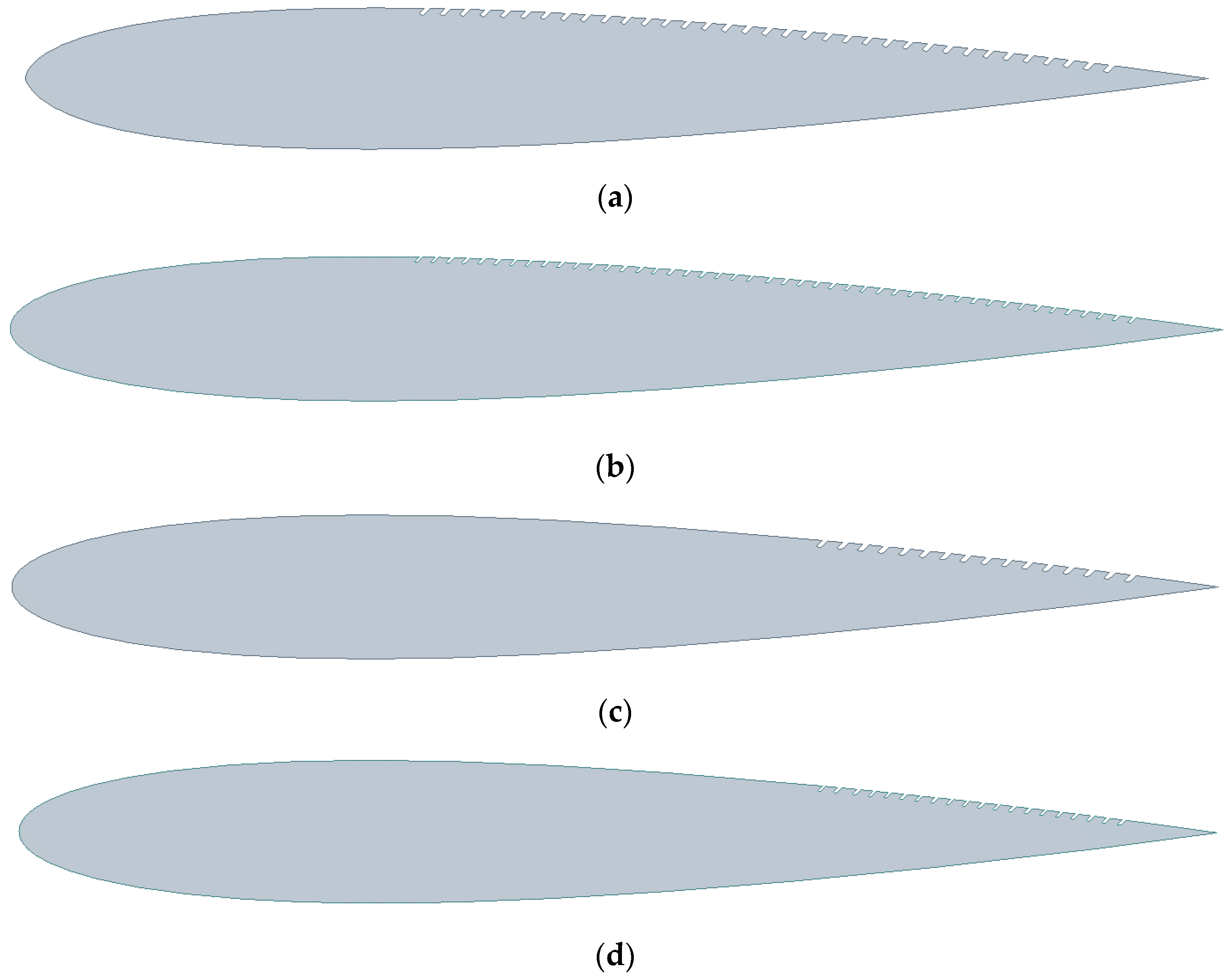
The baseline configuration, denoted as Case 1, corresponds to the unmodified NACA0012 profile. Four modified configurations were generated with 45° inclined perforations by varying both the perforation dimensions and the chordwise extent of the perforated region. The variations were done depending on the chord length (c). In Cases 2 and 3, the perforations were distributed over the downstream two thirds of the extrados, whereas in Cases 4 and 5 the perforations were restricted to the final third of the chord. For Cases 2 and 4, the perforation opening, spacing, and depth were defined as 0.005c, 0.012c, and 0.006c, respectively, while for Cases 3 and 5 the corresponding values were 0.003c, 0.01c, and 0.005c. This parameterization enabled a controlled comparison of the influence of perforation size, density, and placement on the aerodynamic response of the blade section and, subsequently, on the performance of the complete rotor. The two selected chordwise extents were not arbitrary. They were introduced to evaluate how the effectiveness of the passive control concept depends on the location at which it interacts with the developing boundary layer on the extrados. Since the intended role of the perforations was to delay boundary layer separation, one configuration was extended over the downstream two-thirds of the extrados so that the passive control could act over a broader portion of the suction side before separation became fully established. The second configuration, restricted to the final third of the chord, was defined as a more downstream comparison case in order to determine whether a shorter and later control region would still provide an aerodynamic benefit. In this way, the study was designed to assess the sensitivity of the concept to chordwise placement through a controlled proof-of-concept comparison.
Table 1 gives the geometric characteristics of the investigated blades. In the present 2D geometric model, the perforation depth denotes the depth of the inclined cavity in the airfoil cross-section rather than a full 3D through-thickness perforation.
The modified NACA0012 airfoils are illustrated in
Figure 1.
We performed 2D steady-state CFD simulations in ANSYS 19.2 Fluent for all five airfoil geometries. The analysis considered a free stream velocity of 12 m/s and angles of attack ranging from 0° to 180° in increments of 30°, resulting in seven operating points for each profile. The value of 12 m/s was selected for the isolated airfoil stage as a representative moderate Reynolds number condition for comparative aerodynamic screening of the blade sections over a wide incidence range, rather than to reproduce exactly the nominal rotor operating point.
The monitored output quantities were the lift coefficient, drag coefficient, and velocity contours around the airfoil, the latter being used to assess the influence of the perforations on boundary layer development and separation behavior. Accordingly, the perforated cavity geometry was explicitly included in the computational model and mesh for each case, so that its aerodynamic influence was directly resolved in the CFD simulations.
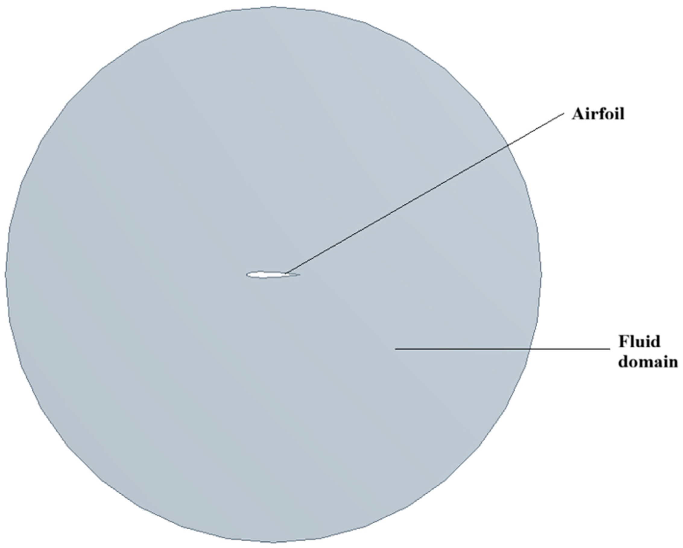
The computational domain for the airfoils simulations was generated in ANSYS 19.2 Design Modeler and consisted of a circular fluid region with a diameter of 3 m, corresponding to approximately ten times the airfoil chord, together with the airfoil solid body embedded within it, as shown in
Figure 2. The airfoil chord used in this stage was 0.3 m.
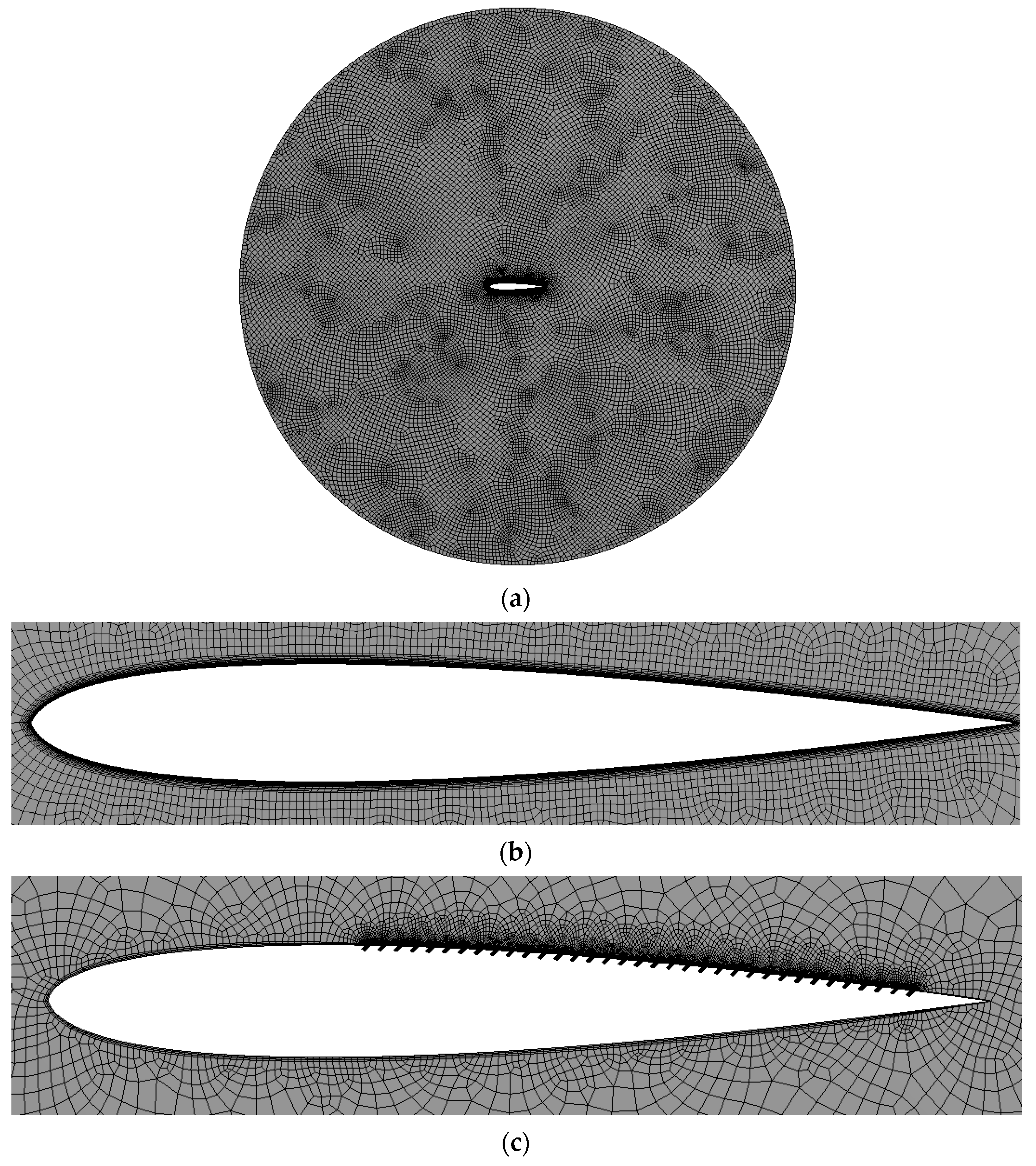
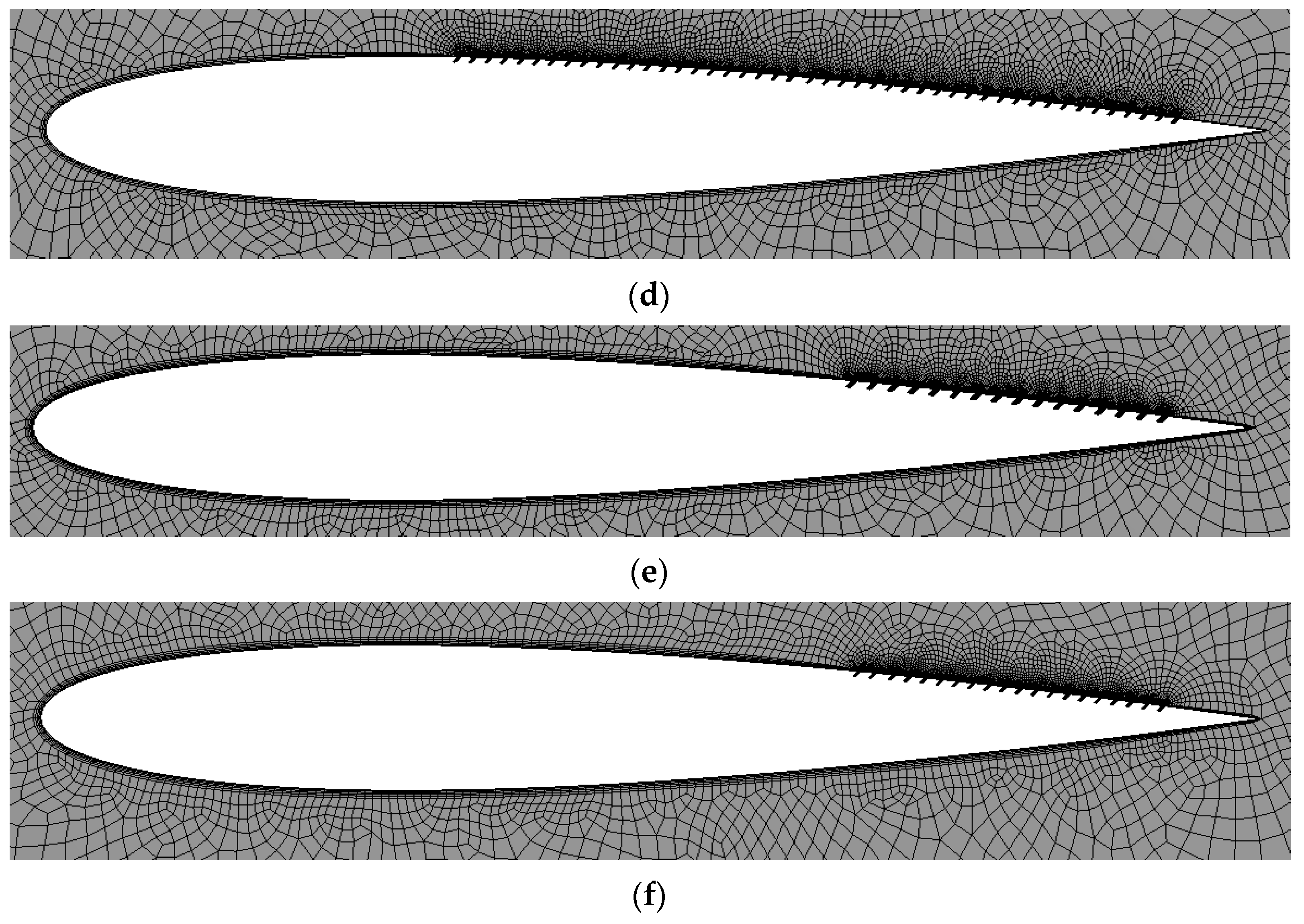
Meshing was performed in ANSYS 19.2 Meshing using a predominantly quadrilateral topology, with a structured near wall region around the airfoil and an unstructured outer flow field. This CFD mesh topology was selected to provide accurate near-wall resolution around the airfoil and perforation regions while maintaining good mesh quality and acceptable computational cost in the outer fluid domain. The airfoil meshes contained approximately 30,000 to 40,000 elements, depending on the specific perforated geometry. The first cell height at the wall was determined from boundary layer relations for a flat plate, based on a Reynolds corresponding to the selected flow conditions. The generated grids are depicted in
Figure 3.
For the airfoil calculations, the k-ω Shear Stress Transport (SST) turbulence model was selected because of its suitability for resolving near wall flow while preserving robust performance in the outer turbulent region. The airfoil surface was prescribed as a stationary wall, while the surrounding fluid domain was treated as a moving fluid domain relative to the profile. Thus, for the isolated airfoil simulations, the boundary conditions consisted of a stationary wall for the airfoil and a surrounding moving fluid domain corresponding to a freestream velocity of 12 m/s. In all simulations, the blade and perforation surfaces were modelled as smooth no-slip walls. Surface roughness effects were not explicitly included in the present comparative CFD analysis. The pressure velocity coupling was handled using the SIMPLE algorithm, with second order spatial discretization. Each simulation was advanced for up to 10,000 iterations, and convergence was assessed using a residual threshold of 10
−6, together with stabilization of the monitored aerodynamic coefficients. In all ANSYS 19.2 Fluent simulations, air was used as the working fluid, while the blade body was assigned aluminum from the default material library. However, since the present work was limited to aerodynamic CFD and the blade surfaces were modelled as rigid walls, the blade material properties did not affect the computed aerodynamic coefficients. A summary of the CFD setup is given in
Table 2.
2.2. Rotor Geometry and Turbine Configuration
Following the airfoil level screening, the five blade profiles were integrated into a straight-bladed VAWT configuration of fixed global geometry. The turbine was pre-dimensioned as an experimental wind tunnel model with 3 blades designed for a nominal wind speed of 10 m/s and a target power of 20 W. Accordingly, the rotor stage CFD simulations were performed at 10 m/s in order to match the nominal design condition adopted for the wind tunnel model. Based on these design assumptions, the rotor diameter resulted D = 0.5 m, rotor radius R = 0.25 m, blade height H = 0.5 m, and blade chord c = 0.1 m. All five rotor cases shared the same global dimensions, differing only in the airfoil geometry used for the blades.
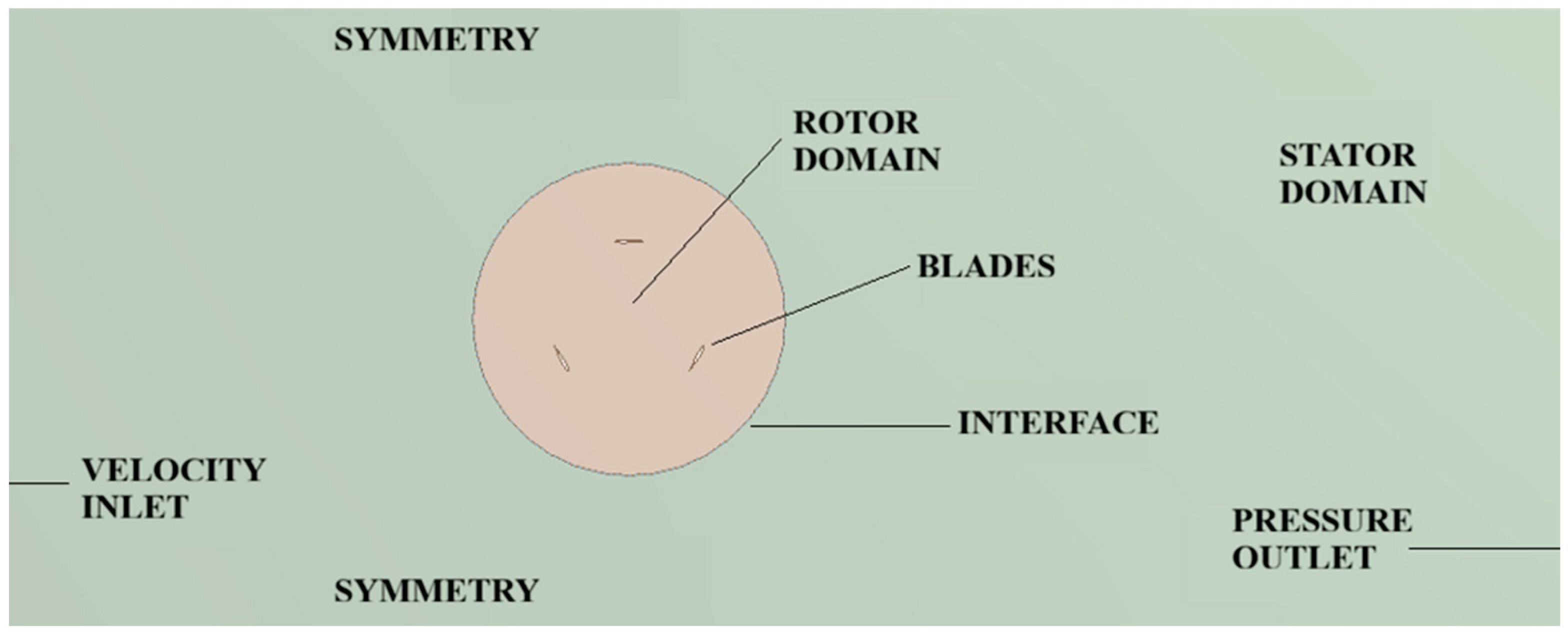
The turbine level CFD analysis was also performed in 2D using ANSYS 19.2 Fluent. The computational domain, illustrated in
Figure 4, was divided into two subdomains: a rotor region and a surrounding stationary fluid region referred to as the stator. The rotor subdomain included the blades, the rotating fluid enclosed by the rotor, and the rotor side interface, whereas the stator subdomain contained the outer fluid region together with the inlet, outlet, symmetry boundaries, and the stator side interface. This arrangement was adopted to reproduce the aerodynamic environment of the planned wind tunnel tests, in which a unidirectional freestream acts on the rotor from left to right.
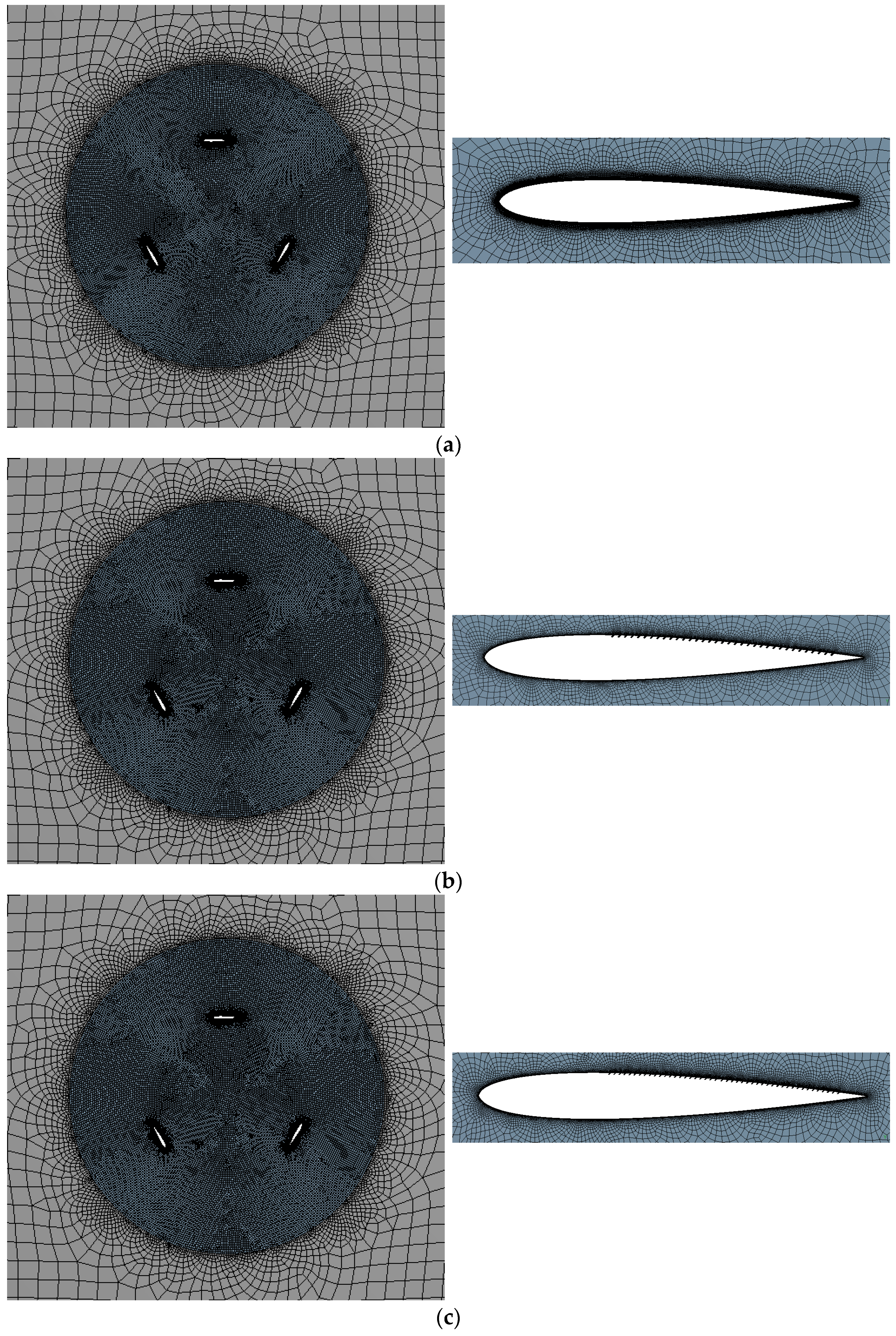
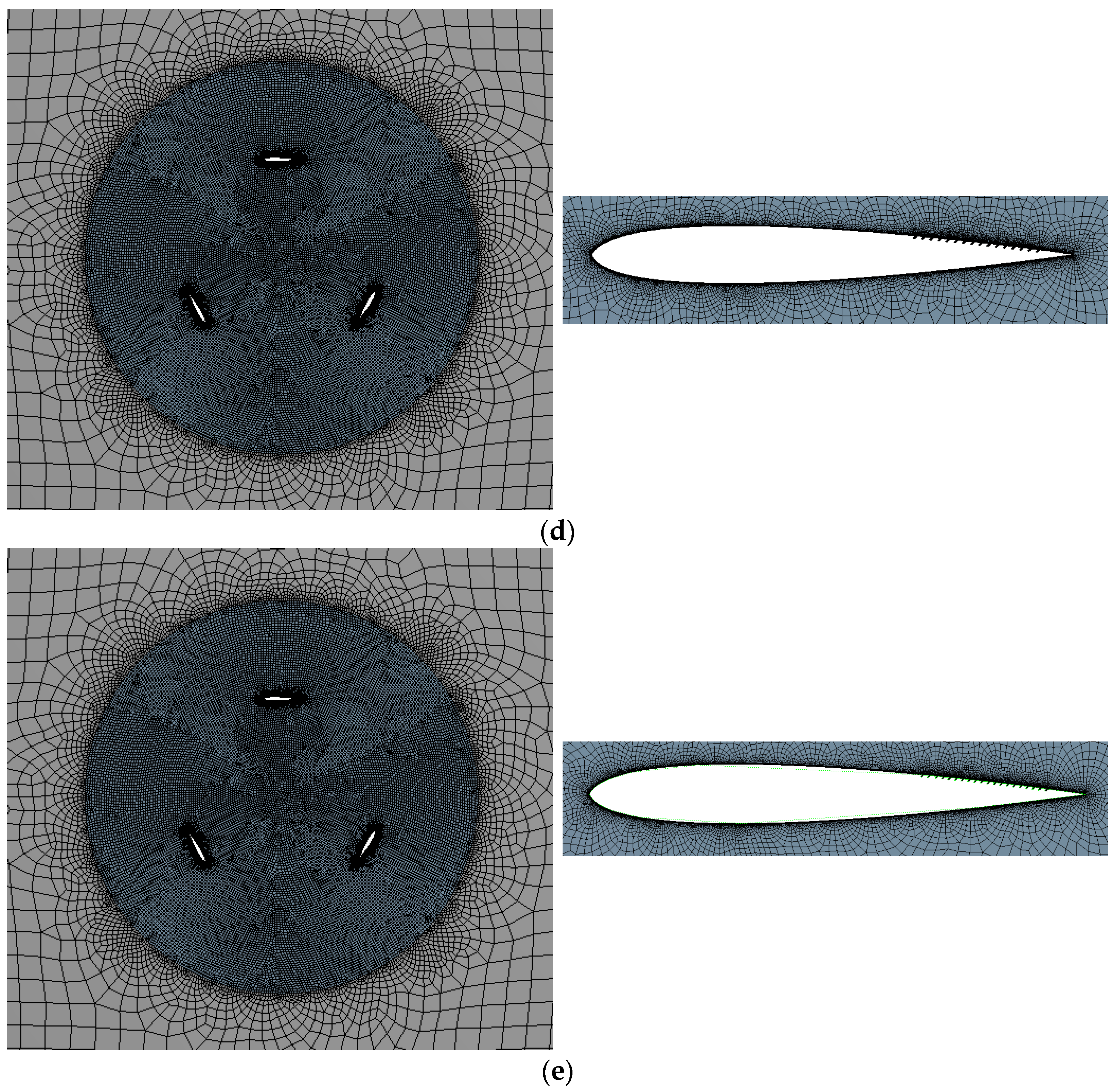
The rotor level computational grids were generated in ANSYS 19.2 Meshing using the quadrilateral dominant method. A structured inflation layer was created around the blade surfaces using 10 layers, with a first cell height of 1 × 10
−5 m. For the perforated cases, an additional structured inflation region with 5 layers was generated around the perforation surfaces using the same first cell height. Edge sizing was applied in the vicinity of the blade surfaces with a first cell size of 1 × 10
−4 m and around the perforations with a first cell size of 3 × 10
−5 m. The rotor interior was meshed using a face sizing value of 6 × 10
−3 m, whereas the stator region used a larger face size of 6 × 10
−2 m. The transition across the rotor–stator interface was controlled through edge divisions of 400 on one side and 600 on the other, with a constant growth rate of 1.2. Depending on the case, the final computational grids contained between 117,833 and 161,163 elements and between 122,144 and 167,747 nodes.
Figure 5 depicts the computational grids for the studied cases.
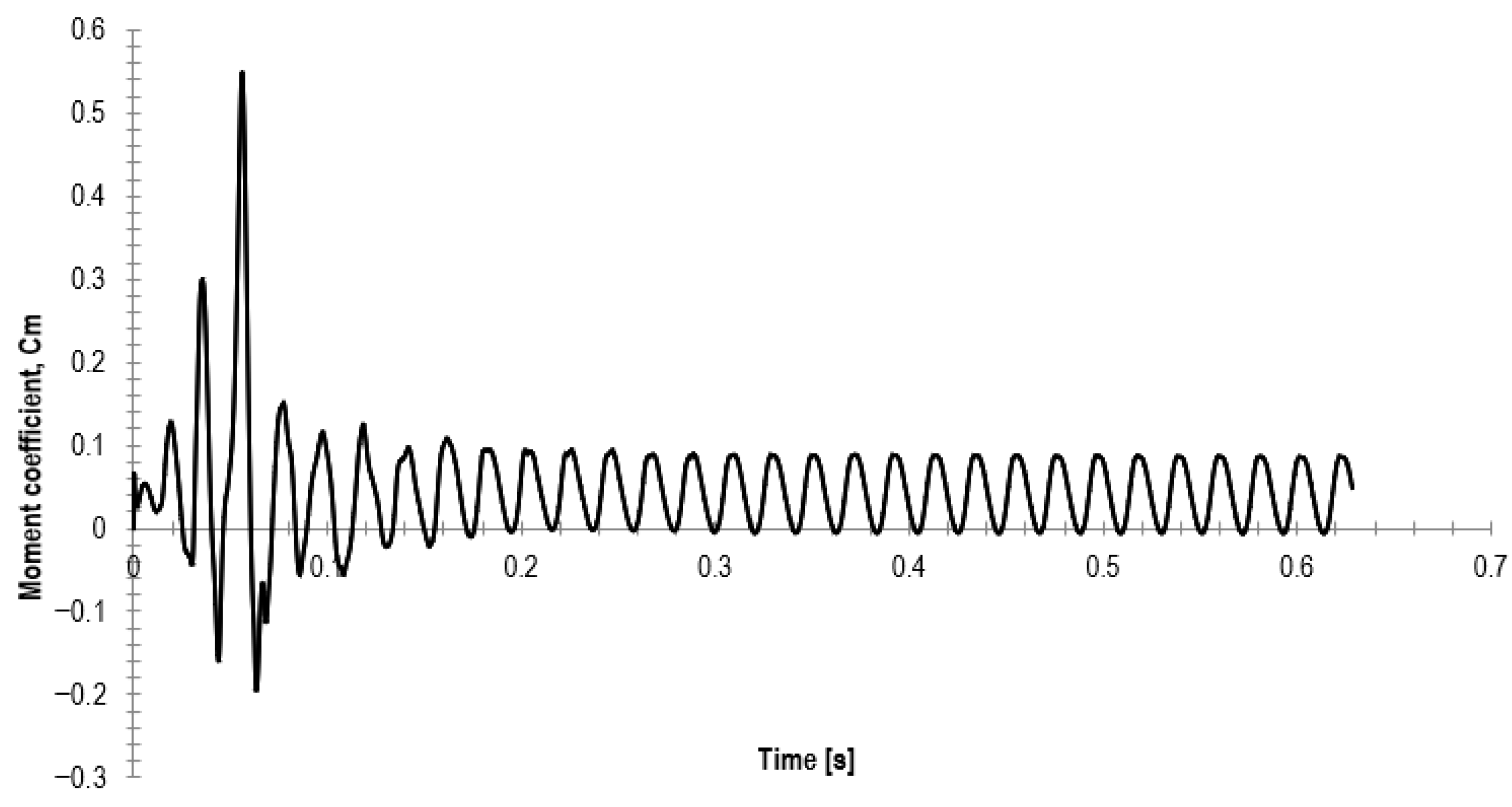
The transient rotor simulations were performed using the Moving Mesh approach in ANSYS 19.2 Fluent. The freestream wind velocity was fixed at 10 m/s, while the angular speed of the rotor was varied so as to reproduce TSRs between 0.5 and 3.5. Seven operating conditions were therefore analyzed for each geometry, corresponding to angular velocities of 20, 40, 60, 80, 100, 120, and 140 rad/s, respectively. The simulations were run for seven complete revolutions of the rotor, since the periodic behavior of the instantaneous moment coefficient indicated that this duration was sufficient to achieve a repeatable quasi-periodic flow field under the Moving Mesh formulation, as illustrated in
Figure 6. This figure presents the time history of the instantaneous moment coefficient obtained at each time step during the transient simulation and was used to verify that the solution reached a repeatable quasi-periodic regime over successive revolutions. The time step was chosen such that the rotor advanced by 1° per time step, leading to 2520 time steps for each full simulation.
The time-step value therefore varied with angular speed, from 0.00087 s at TSR = 0.5 to 0.00012 s at TSR = 3.5. A maximum of 50 iterations was permitted per time step. As in the airfoil level study, the k-ω SST turbulence model was adopted, pressure velocity coupling was handled with the SIMPLE scheme, and second order discretization was used. Convergence was assessed by imposing residuals of order 10−6 for the governing equations and by monitoring the temporal evolution of the moment coefficient. The boundary conditions used in the transient turbine simulations were as follows: the blades and perforation surfaces were modeled as walls; the rotor fluid region was assigned a mesh motion condition with the prescribed angular velocity; the outer stator region remained stationary; and the interface between the two subdomains was defined as a rotor–stator interface. The imposed freestream was unidirectional, from left to right, in accordance with the intended wind tunnel setup. More specifically, the stator domain included a velocity inlet, a pressure outlet, and symmetry boundaries, while the blades and perforation surfaces were modelled as walls, the rotor region was assigned mesh motion, and the rotor and stator were connected through a rotor–stator interface.
The main monitored quantity during the transient simulations was the moment coefficient. Once a periodic response was obtained, a revolution averaged moment coefficient was extracted and used to compute the corresponding power coefficient. Seven complete revolutions were judged sufficient to obtain a stable periodic response for the present comparative analysis. A summary of the setup for this study is given in
Table 3.
2.3. Performance Parameters
At airfoil level, the primary output quantities were the lift and drag coefficients, evaluated as functions of angle of attack. At rotor level, the main performance indicator was the moment coefficient, monitored throughout the rotational cycle. In the present CFD framework, the blade loads were not prescribed as external structural loads, but were generated aerodynamically from the computed pressure and viscous forces acting on the blade surfaces under the imposed freestream and rotational operating conditions. The mean power coefficient was then determined from Equation (1):
where c
m is the mean moment coefficient over one complete revolution and
, where
is the rotor angular velocity,
is the rotor radius, and
is the freestream velocity. Based on these coefficients, the mean useful torque and power were also determined for each operating condition. The transient simulations were therefore used to construct the characteristic curve c
p (TSR) the investigated geometries.
2.4. Comparative Evaluation Strategy
The adopted methodology followed a two-stage comparative screening strategy. In the first stage, the modified airfoils were compared against the baseline NACA0012 profile in order to identify the effect of perforation geometry on lift, drag, and separation behavior over a wide incidence range. In the second stage, the same blade geometries were assessed at rotor level under identical turbine dimensions and operating conditions, such that the influence of blade modification on moment and power characteristics could be evaluated. This approach was intended to identify the most promising passive control configuration before proceeding to 3D simulations and experimental validation.
2.5. Mesh Independence Study
To assess the numerical reliability of the rotor level CFD framework, a mesh independence study was carried out for the baseline turbine configuration. Three systematically refined computational grids were considered: a coarse grid with approximately 20% fewer elements than the reference mesh, a medium grid corresponding to the mesh used in the main rotor calculations, and a fine grid with approximately 20% more elements than the reference mesh. These grids contained approximately 94,266, 117,833, and 141,400 elements, respectively.
All three meshes were evaluated using the same transient Moving Mesh formulation adopted in the main study, with identical boundary conditions and solver settings. In particular, the simulations were performed for a freestream velocity of 10 m/s over a TSR range of 0.5–3.5, using seven complete revolutions, 2520 time steps, an angular increment of 1° per time step, and a residual convergence criterion of 10−6. The comparison was based on the mean moment coefficient and the corresponding power coefficient computed over one complete revolution.
The results indicated that the difference between the medium and fine meshes was limited throughout the operating range investigated, whereas the coarse mesh showed somewhat larger deviations. This behavior confirms that the solution had reached practical mesh independence at the medium grid level. Since the fine mesh only produced minor changes while requiring additional computational effort, the medium mesh was adopted for this study as the most appropriate compromise between solution accuracy and computational cost. This choice is consistent with the mesh independence study results, reported in
Table 4, where the differences between the medium and finer grids were found to be negligible in terms of overall performance trends.
3. Results
3.1. Airfoil Numerical Evaluation
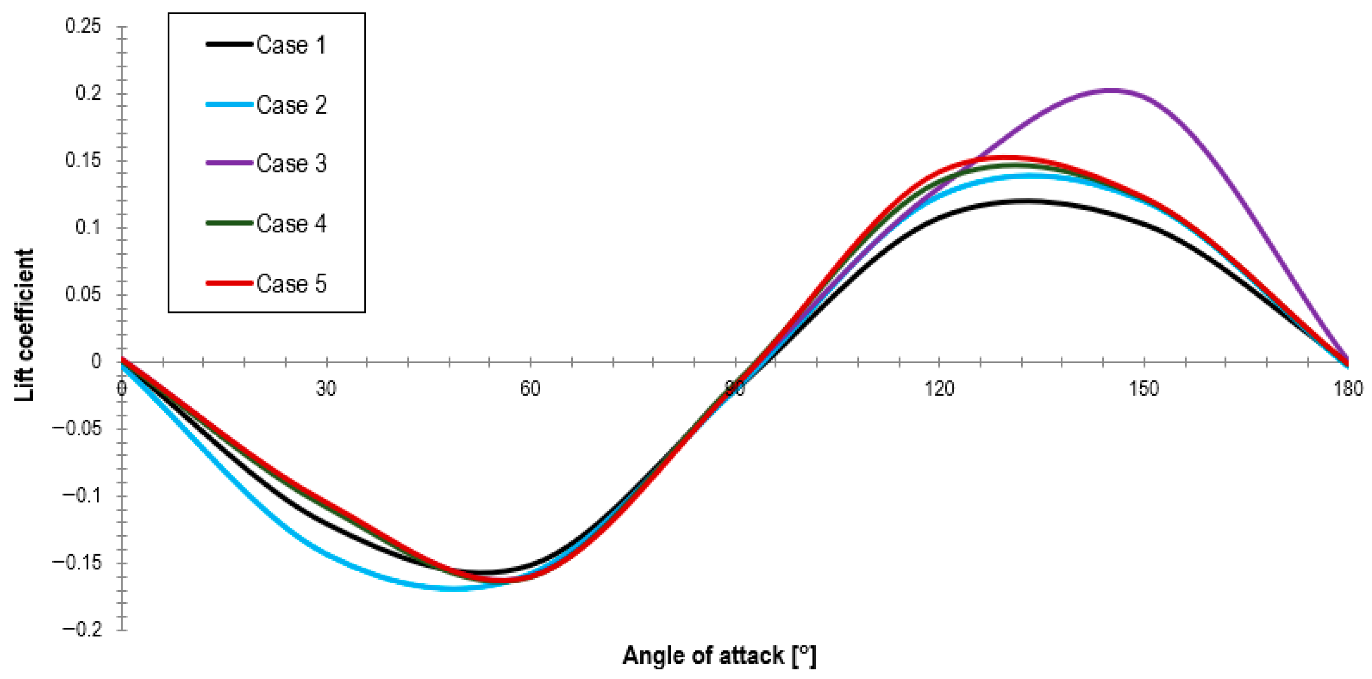
The steady-state 2D simulations performed for the isolated airfoils showed that all perforated configurations improved the lift coefficient relative to the baseline NACA0012 profile over relevant portions of the investigated angle of attack range. Among the modified geometries, Case 3 exhibited the highest lift coefficient, indicating the most favorable aerodynamic response of the five configurations considered. The lift coefficient variation with the angle of attack is illustrated in
Figure 7, which presents the converged lift coefficient values obtained from the steady CFD simulations at incidence angles between 0° and 180° in 30° increments.
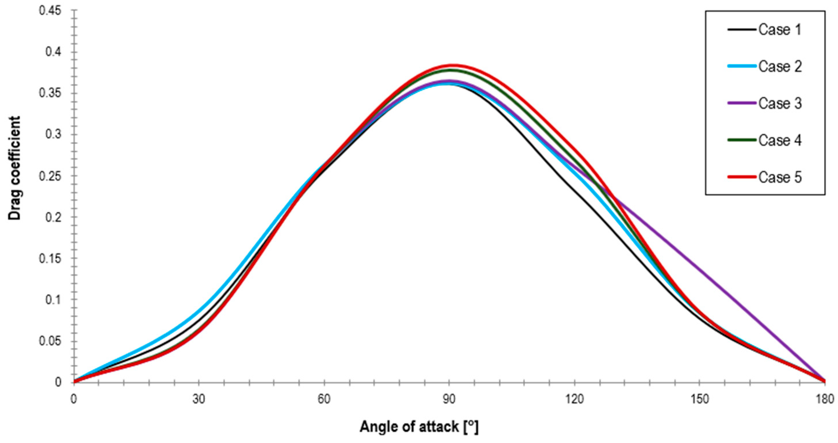
At the same time, the drag response revealed a clear dependence on perforation placement: Cases 4 and 5, for which the inclined perforations were restricted to the final third of the extrados, produced the highest drag levels, whereas Case 3 maintained a maximum drag coefficient approximately comparable to those of Cases 1 and 2. Consequently, the introduction of inclined perforations over the downstream two thirds of the extrados improved lift without producing a comparable drag penalty, with Case 3 providing the best overall sectional compromise. The drag coefficient variation with the angle of attack is shown in
Figure 8.
The best balance was obtained for Case 3, which combined smaller perforation openings with smaller spacing and extended the perforated region over the last two-thirds of the extrados. This configuration produced the highest lift response among the tested variants, while its maximum drag remained approximately comparable to the baseline and to Case 2. By contrast, Cases 4 and 5, in which the perforations were restricted to the last third of the chord, exhibited the largest drag penalties.
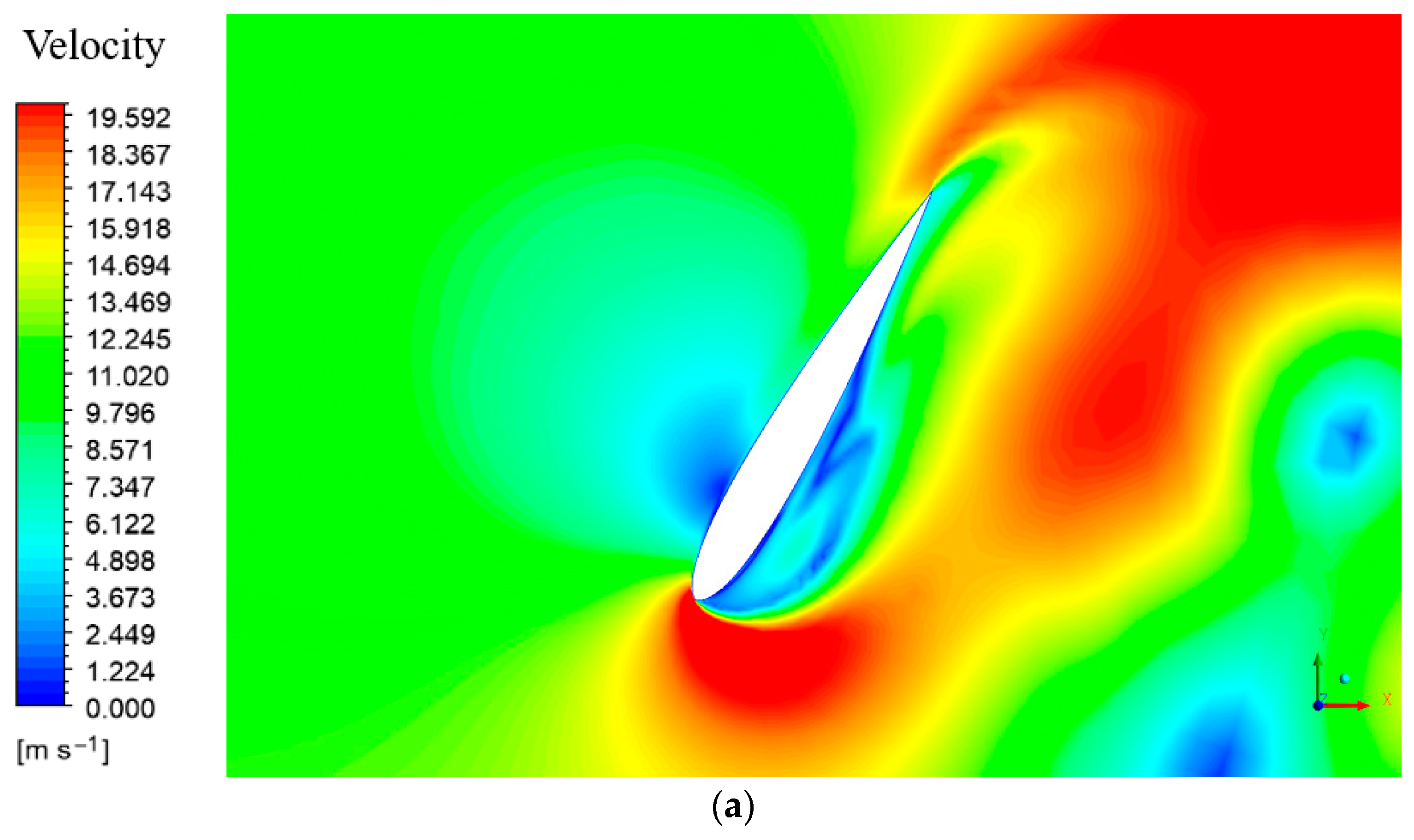
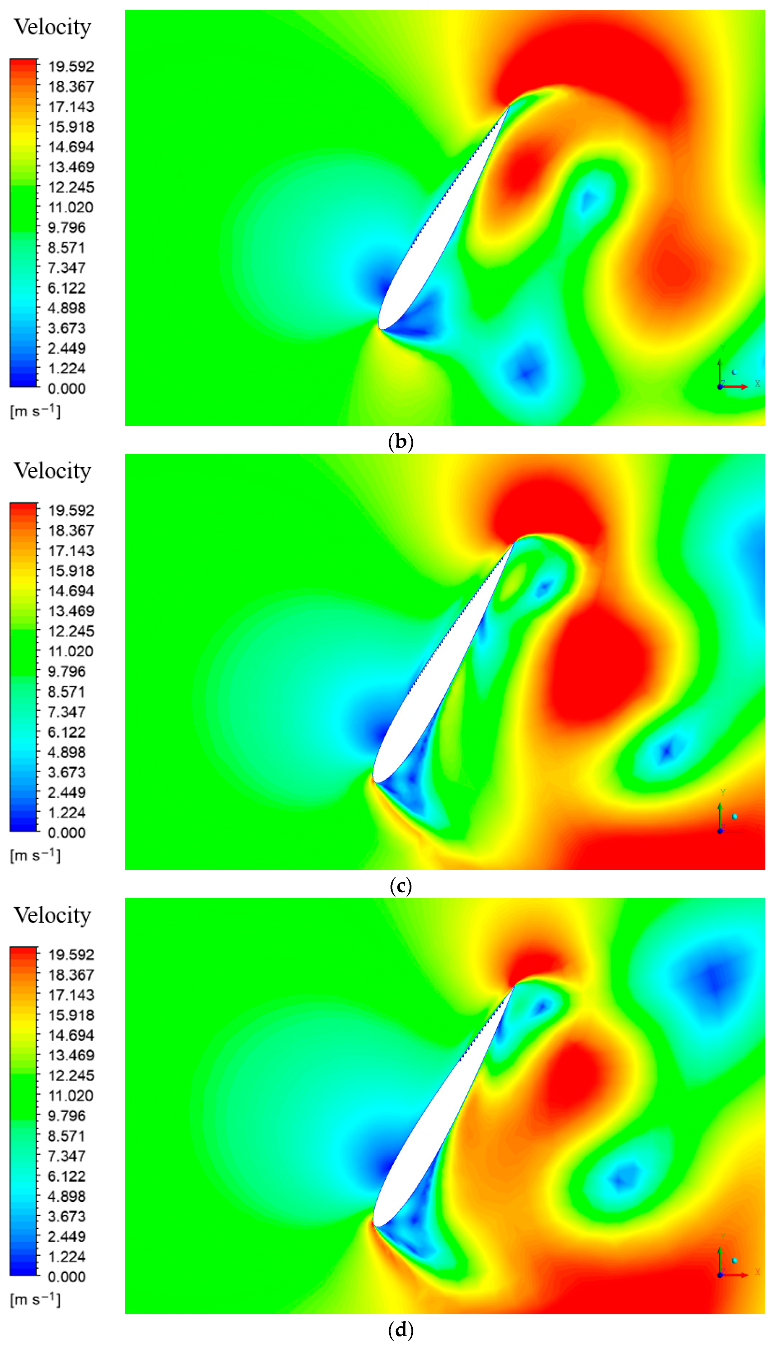
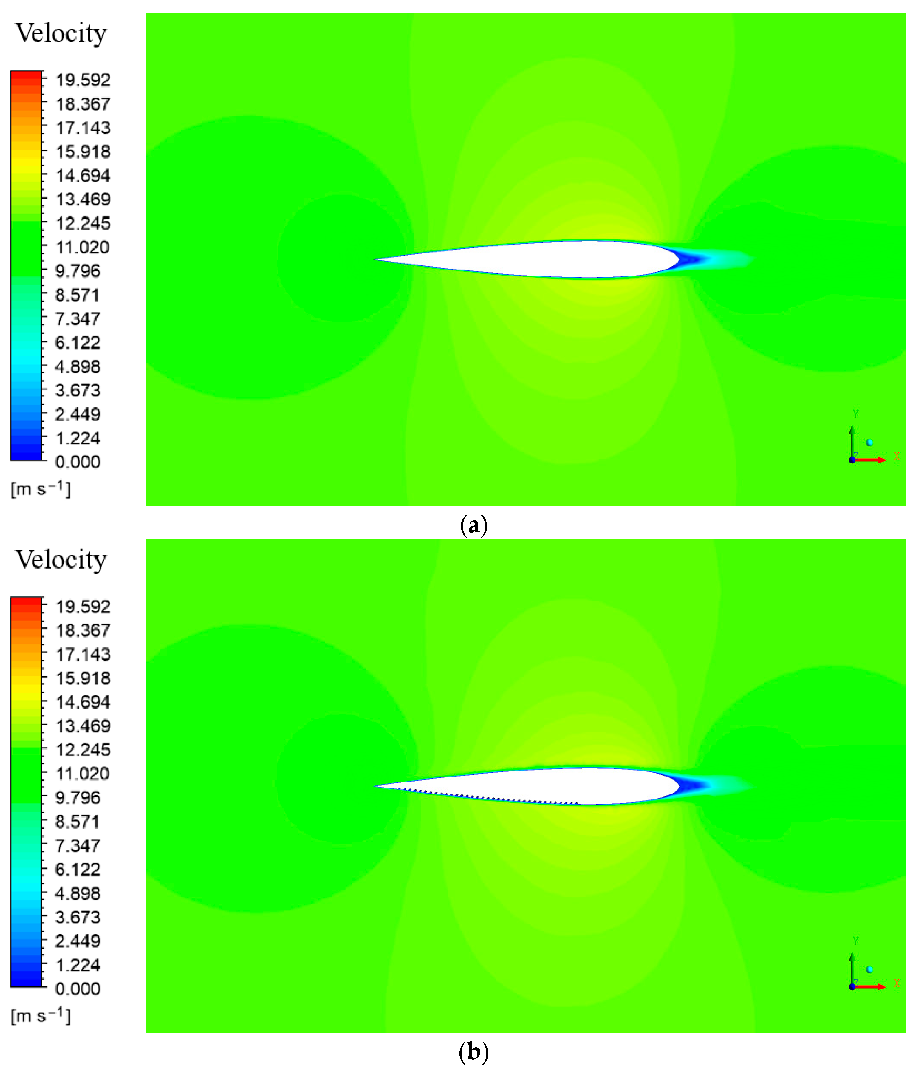
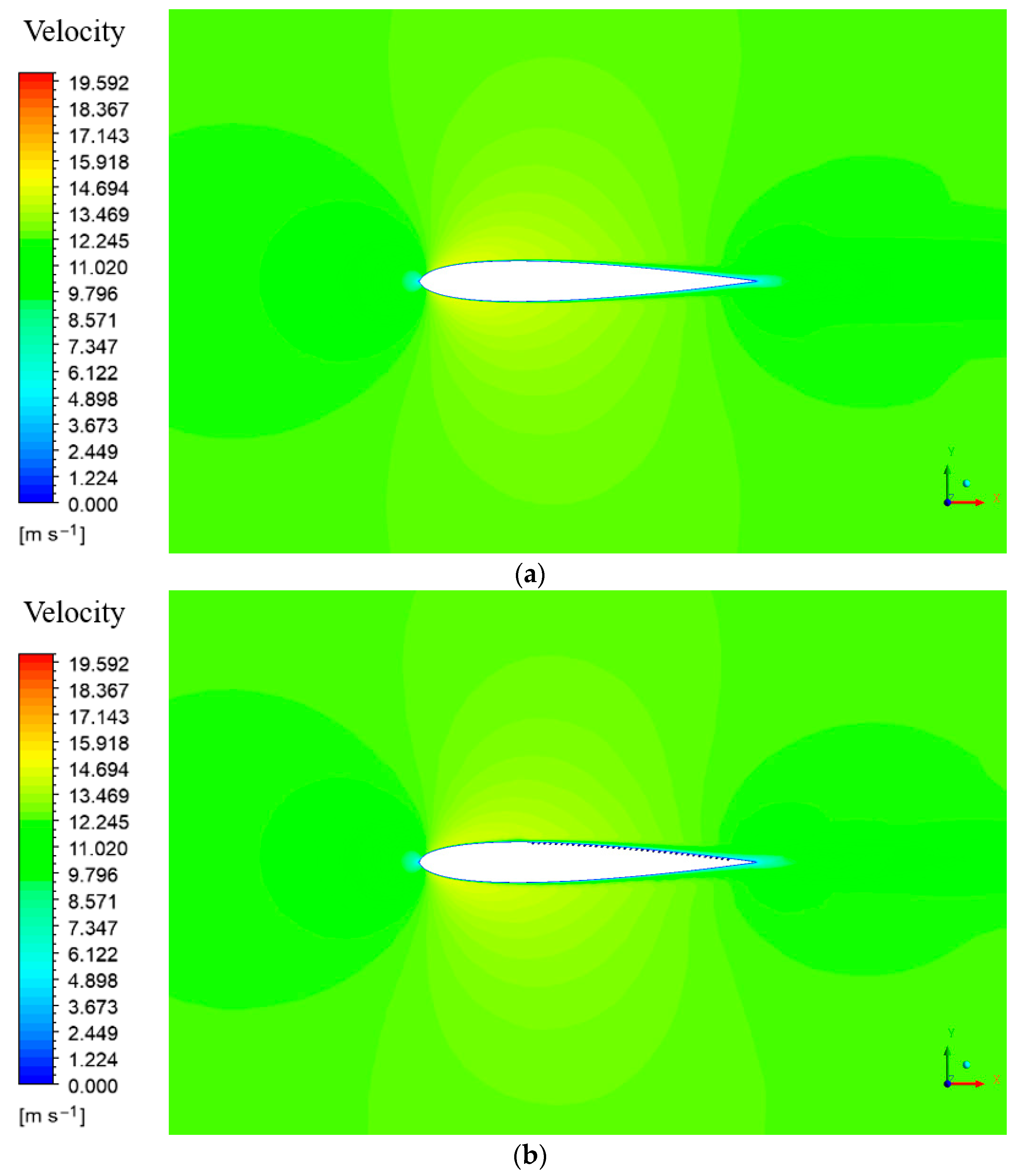
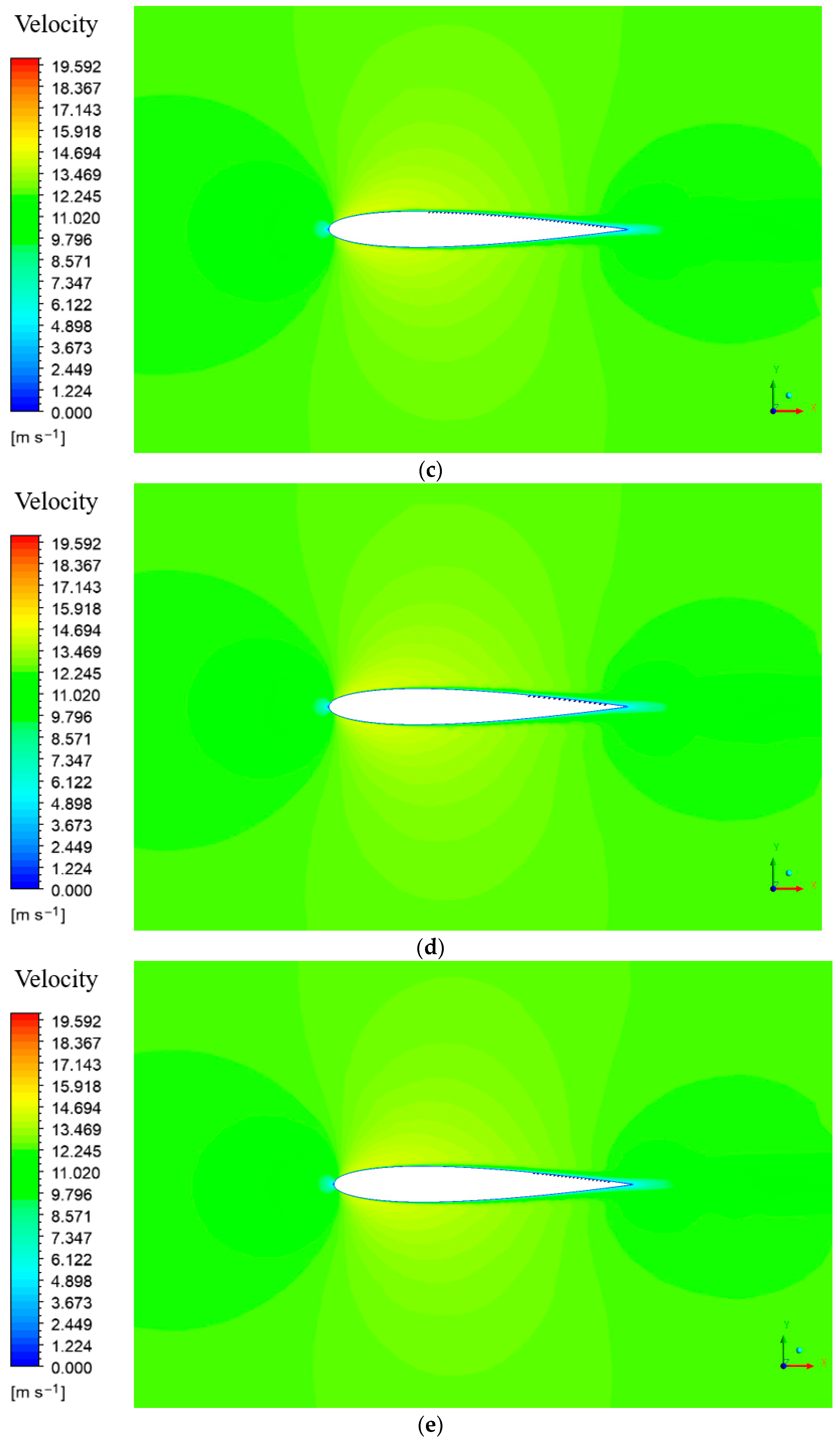
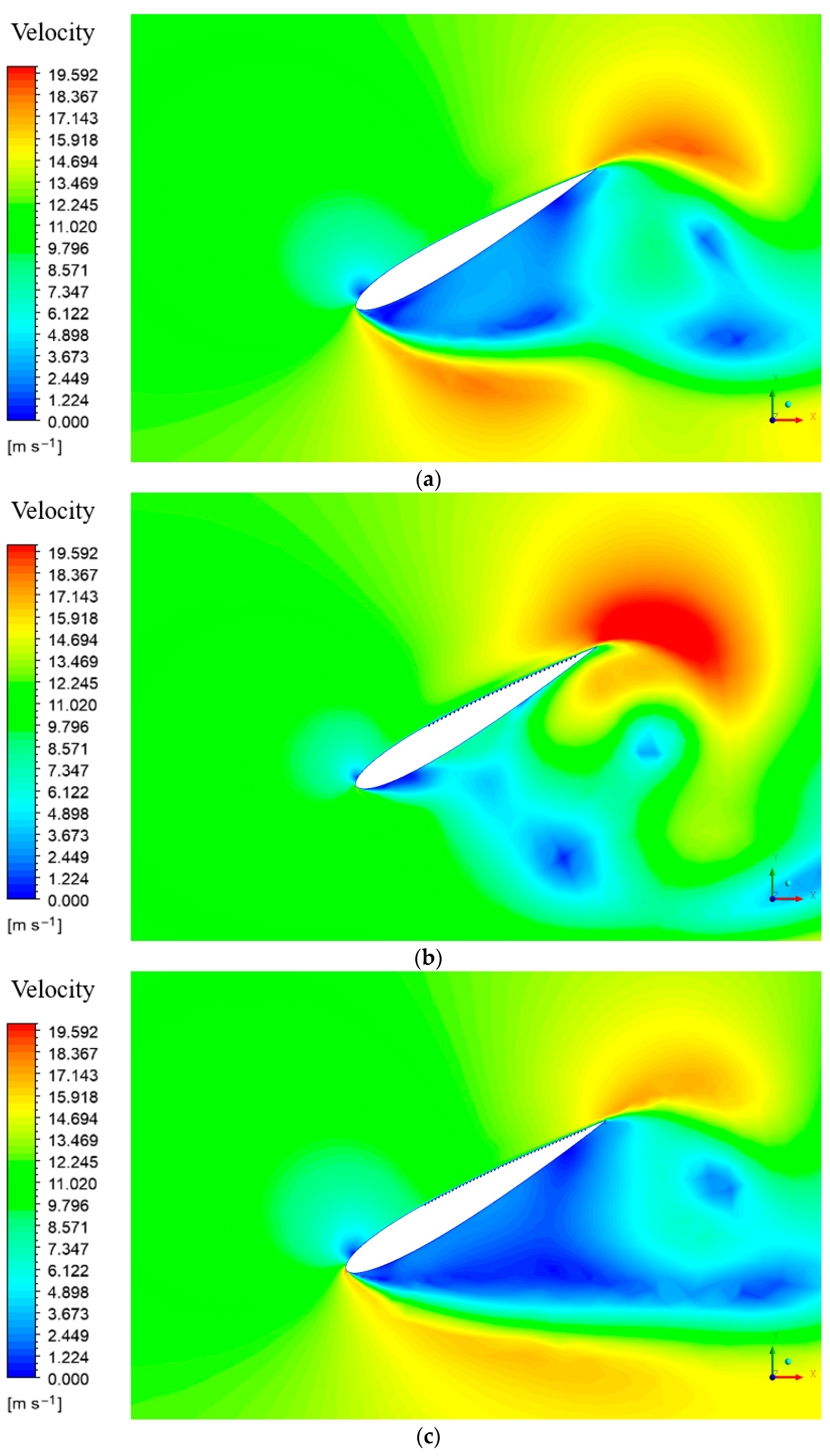
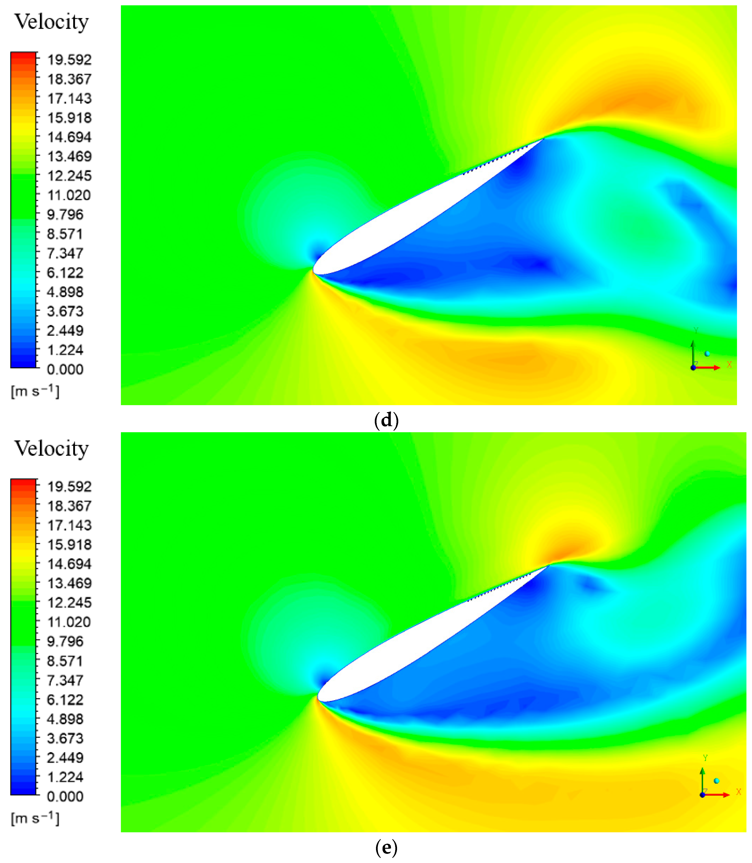
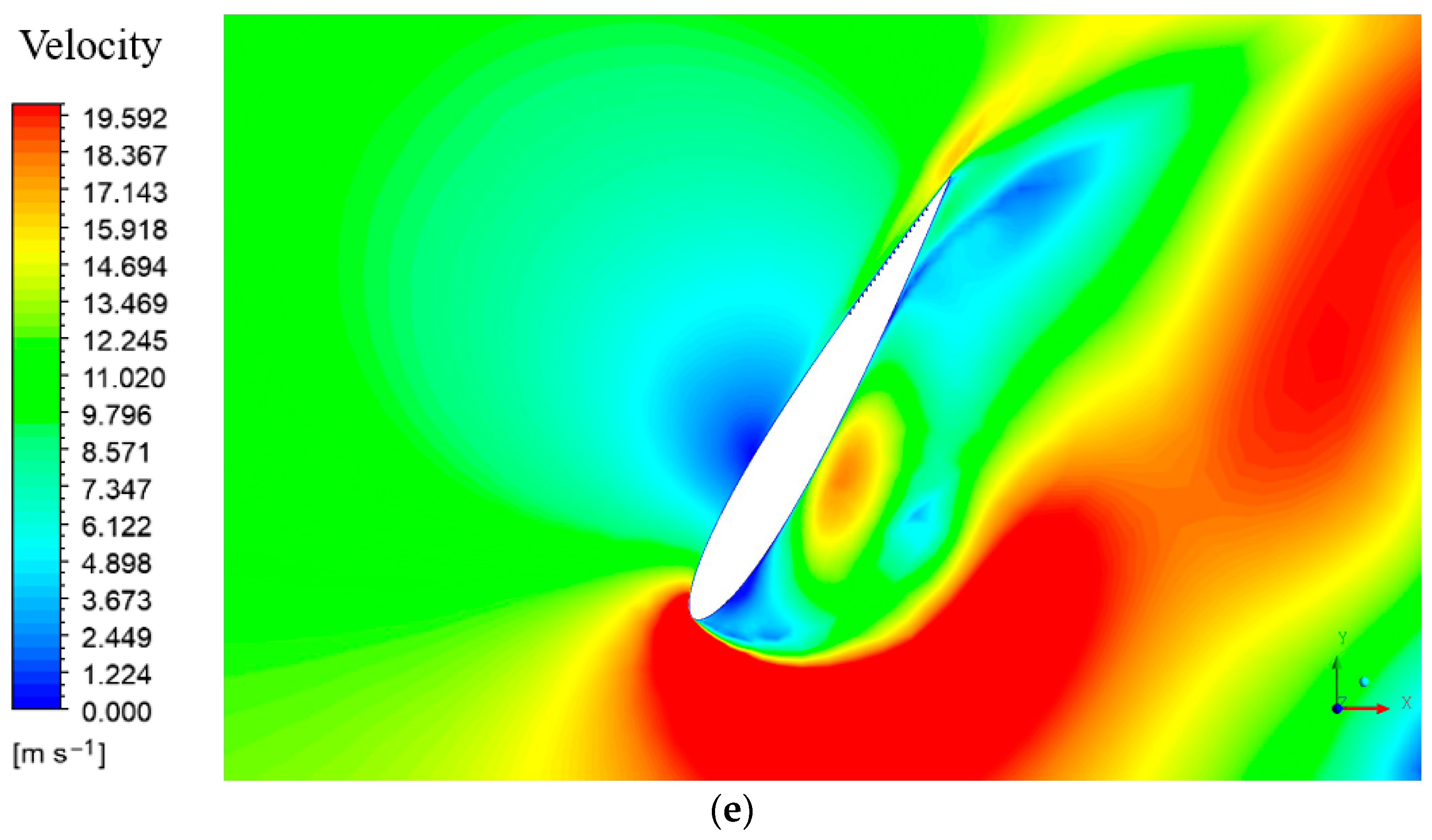
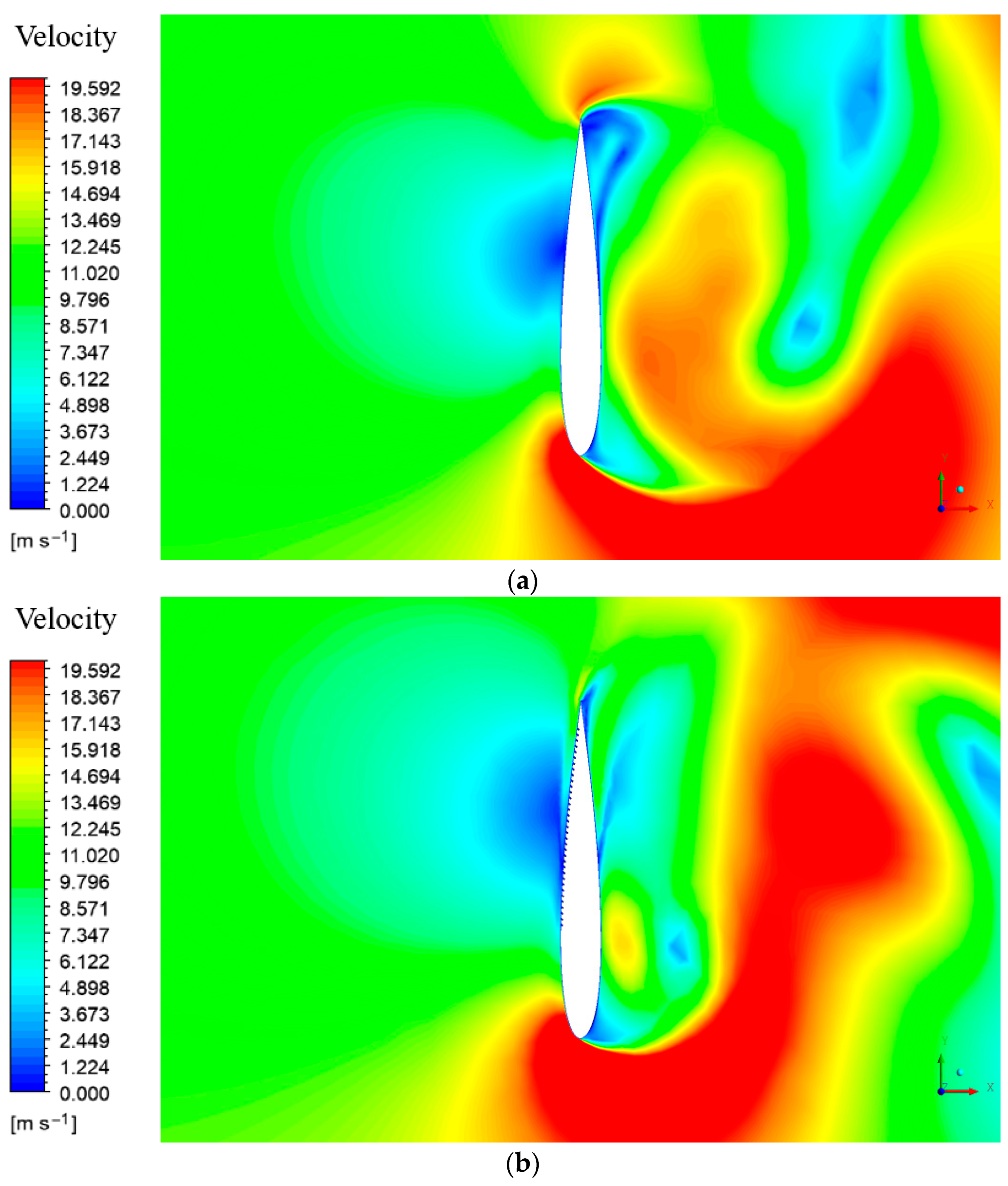
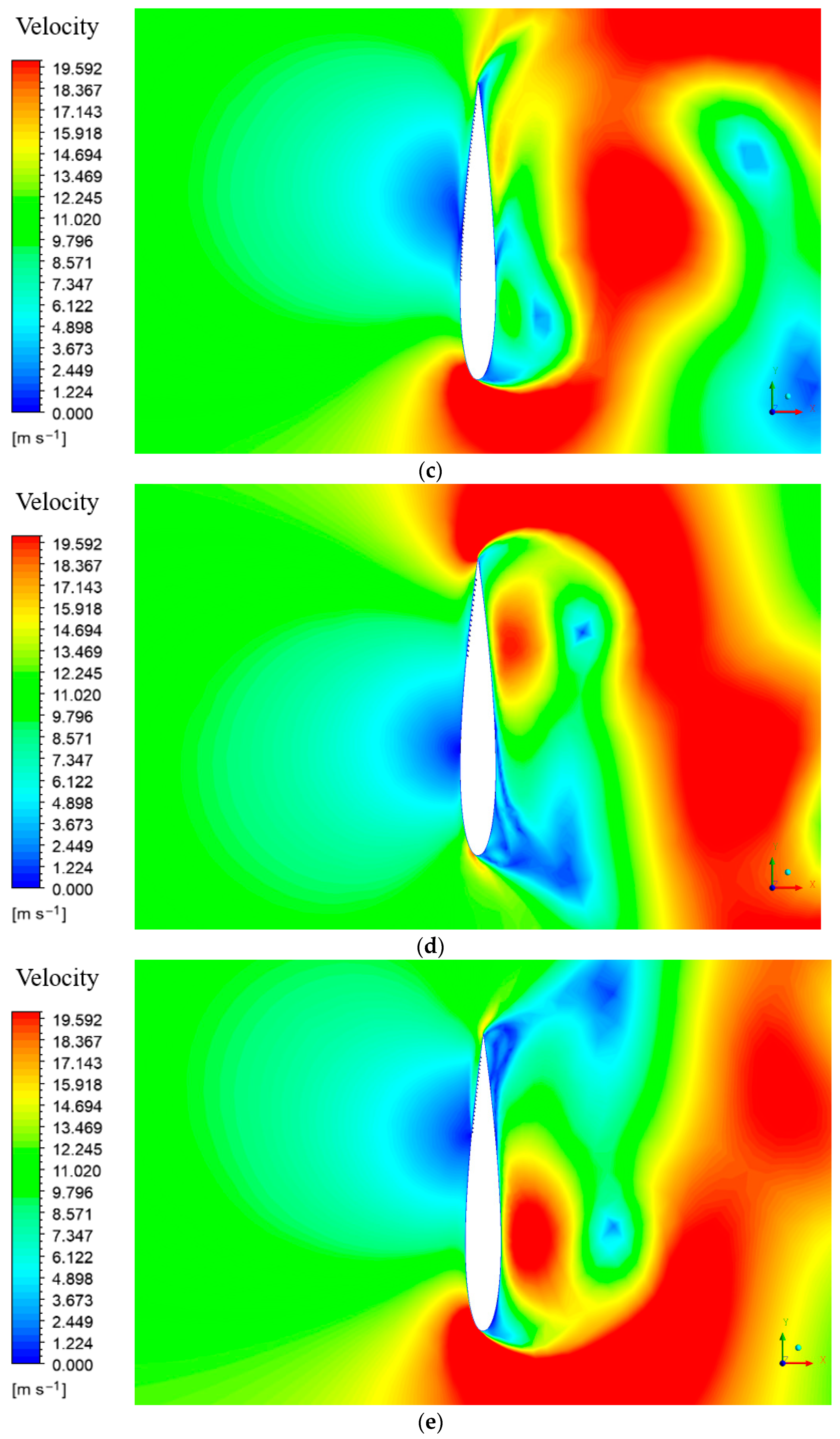
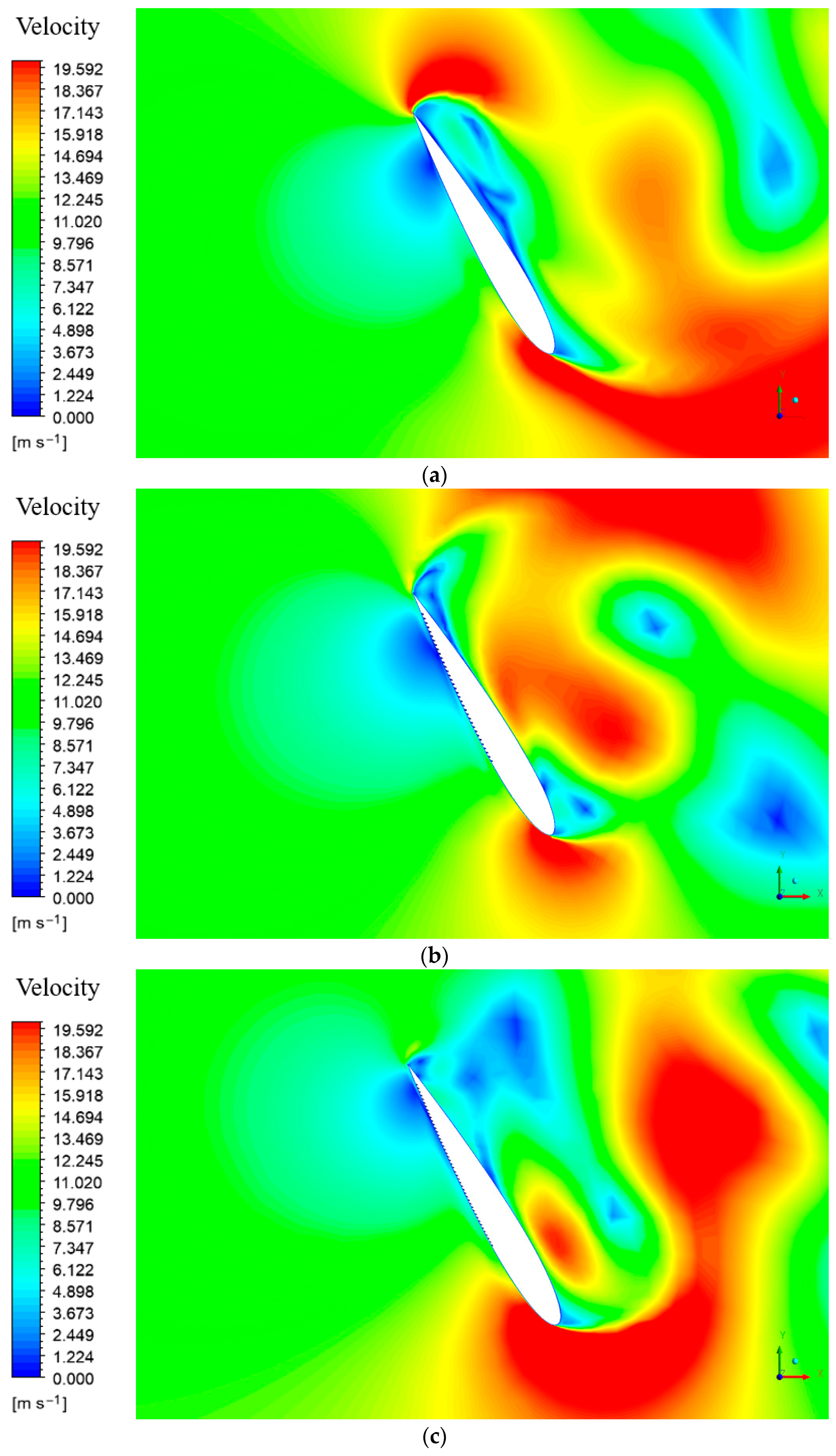
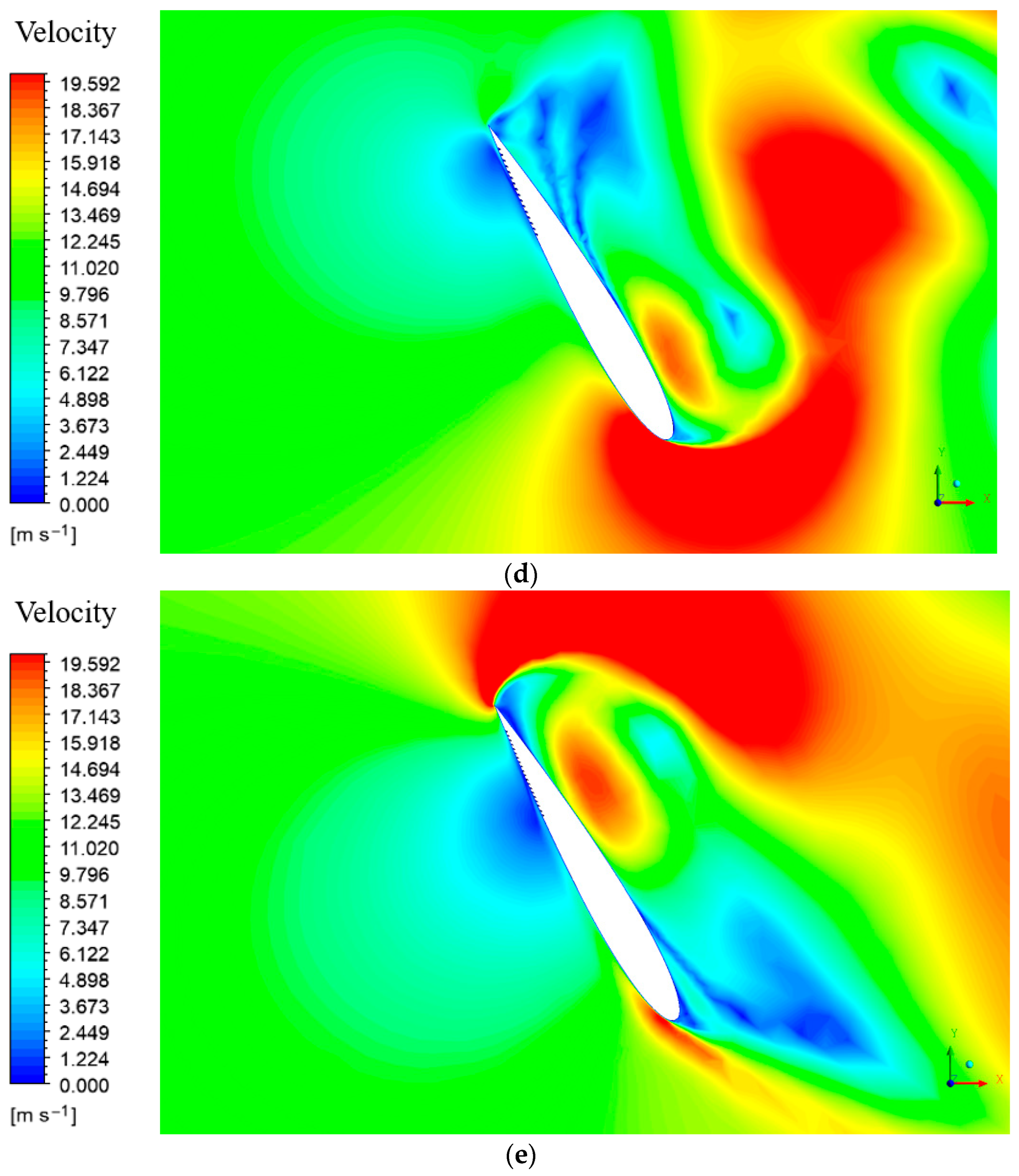
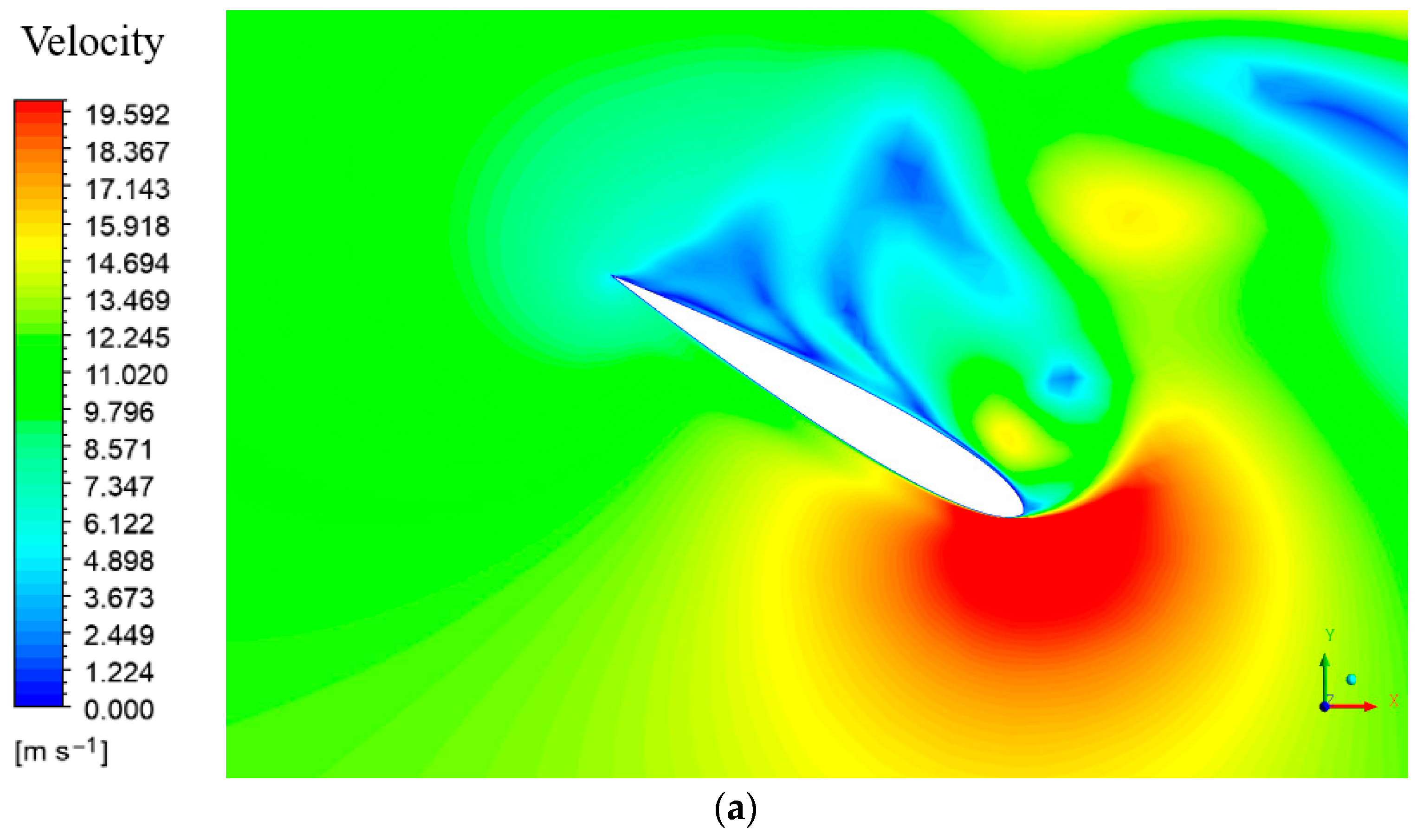
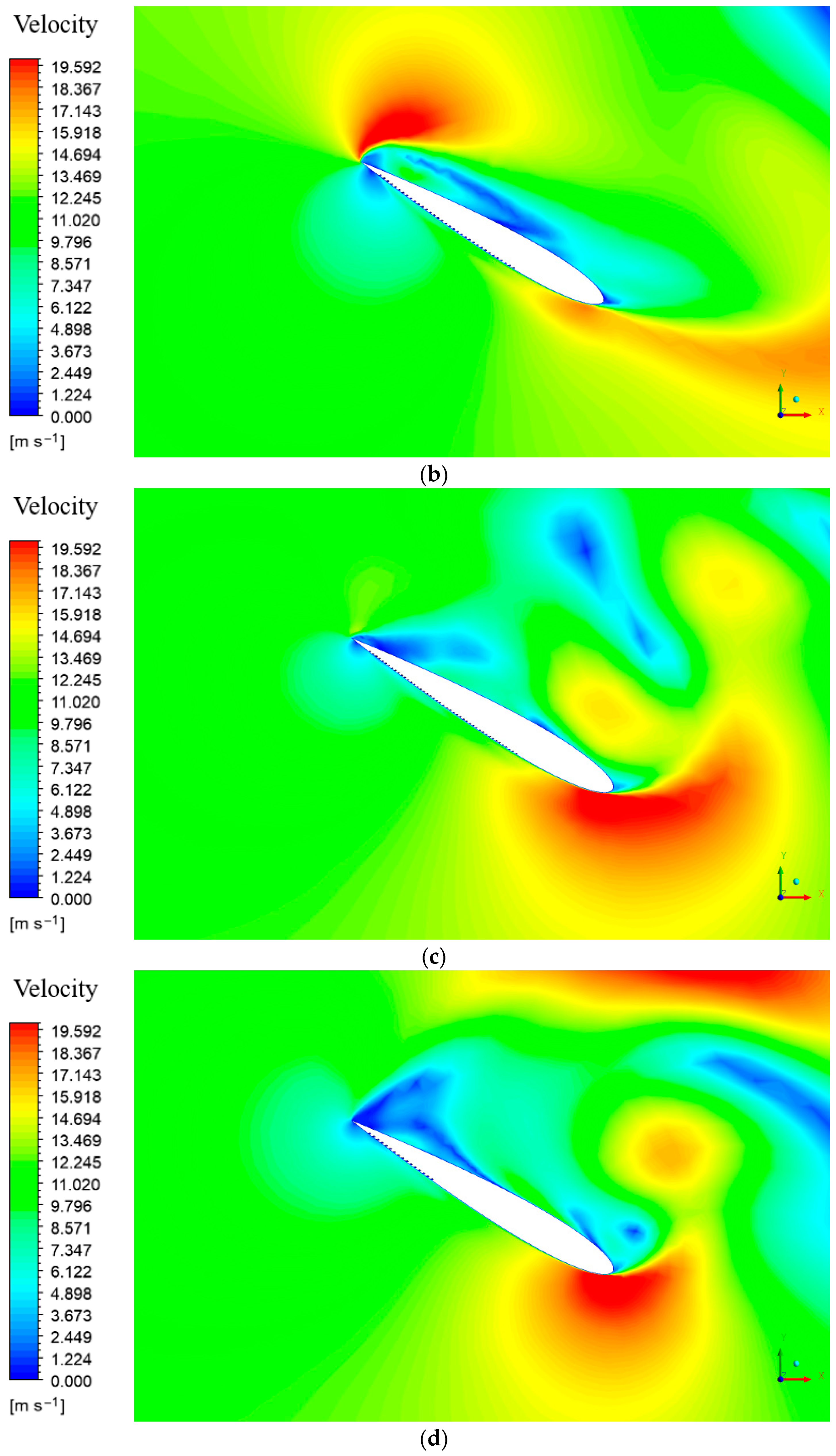
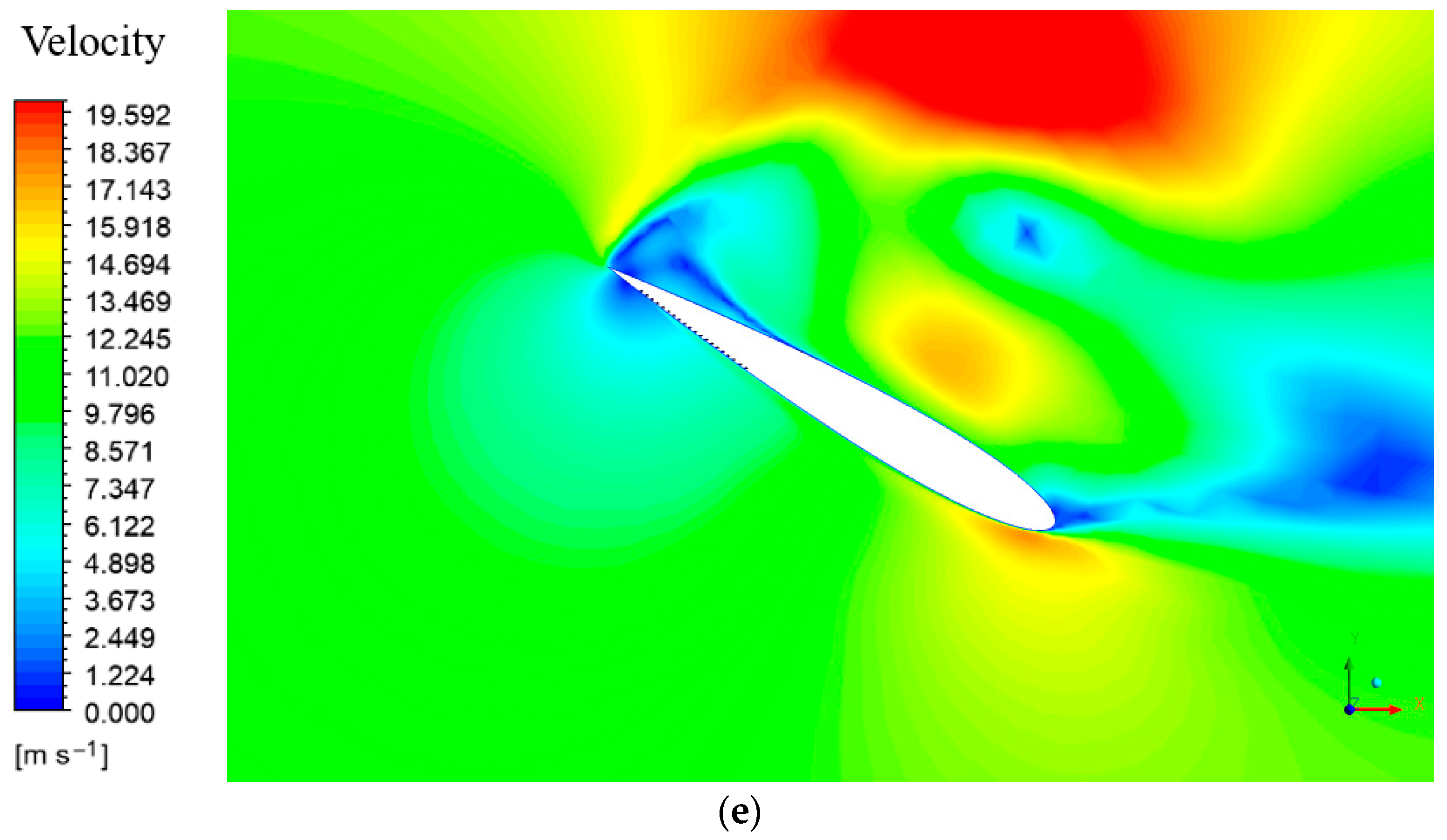
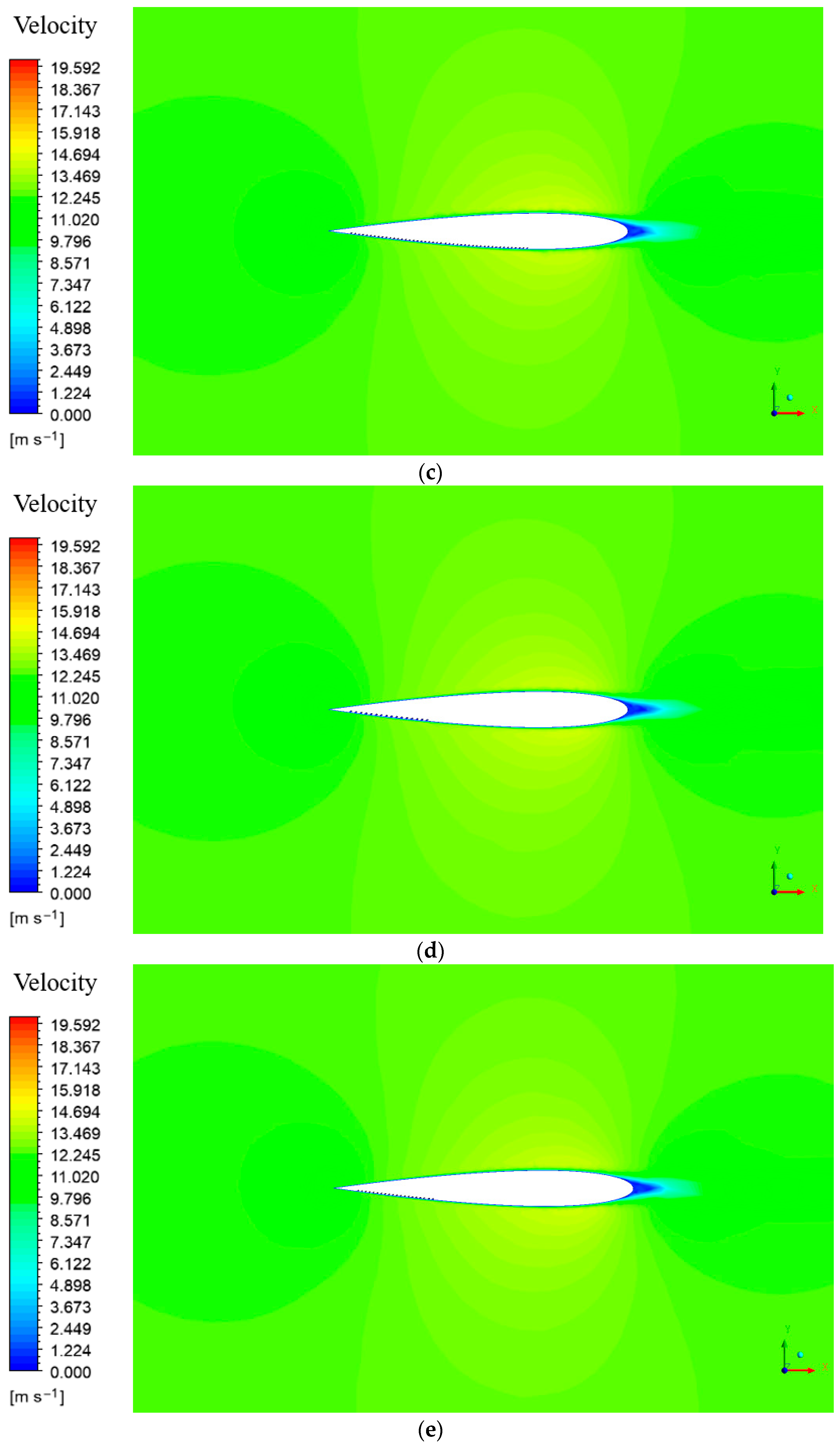
The velocity contours further support this trend. Across the investigated incidence range, the perforated profiles delayed boundary layer separation relative to the baseline airfoil, and this effect was reported to be most evident at an angle of attack of 60°. It is indicated that perforations become effective only when they act early enough along the extrados to influence the separation process before the wake is fully developed. This observation is consistent with the superior lift response obtained for Cases 2 and 3 and provides a plausible aerodynamic explanation for the better turbine level performance later observed for the corresponding rotor configurations. The velocity contours are given in
Figure 9,
Figure 10,
Figure 11,
Figure 12,
Figure 13,
Figure 14 and
Figure 15. In these figures, the displayed quantity is the velocity magnitude from Equation (2), obtained from the converged 2D CFD solution:
where
and
denote the x and y components of velocity, respectively.
3.2. Rotor Numerical Evaluation
The transient rotor simulations confirmed that the isolated airfoil trends were preserved at system level. The mean moment coefficient was strongly influenced by blade geometry. For the baseline rotor, the maximum power coefficient occurred at TSR = 2.5. Case 2 also performed strongly, but Case 3 produced the highest average power coefficient over a full revolution among all configurations.
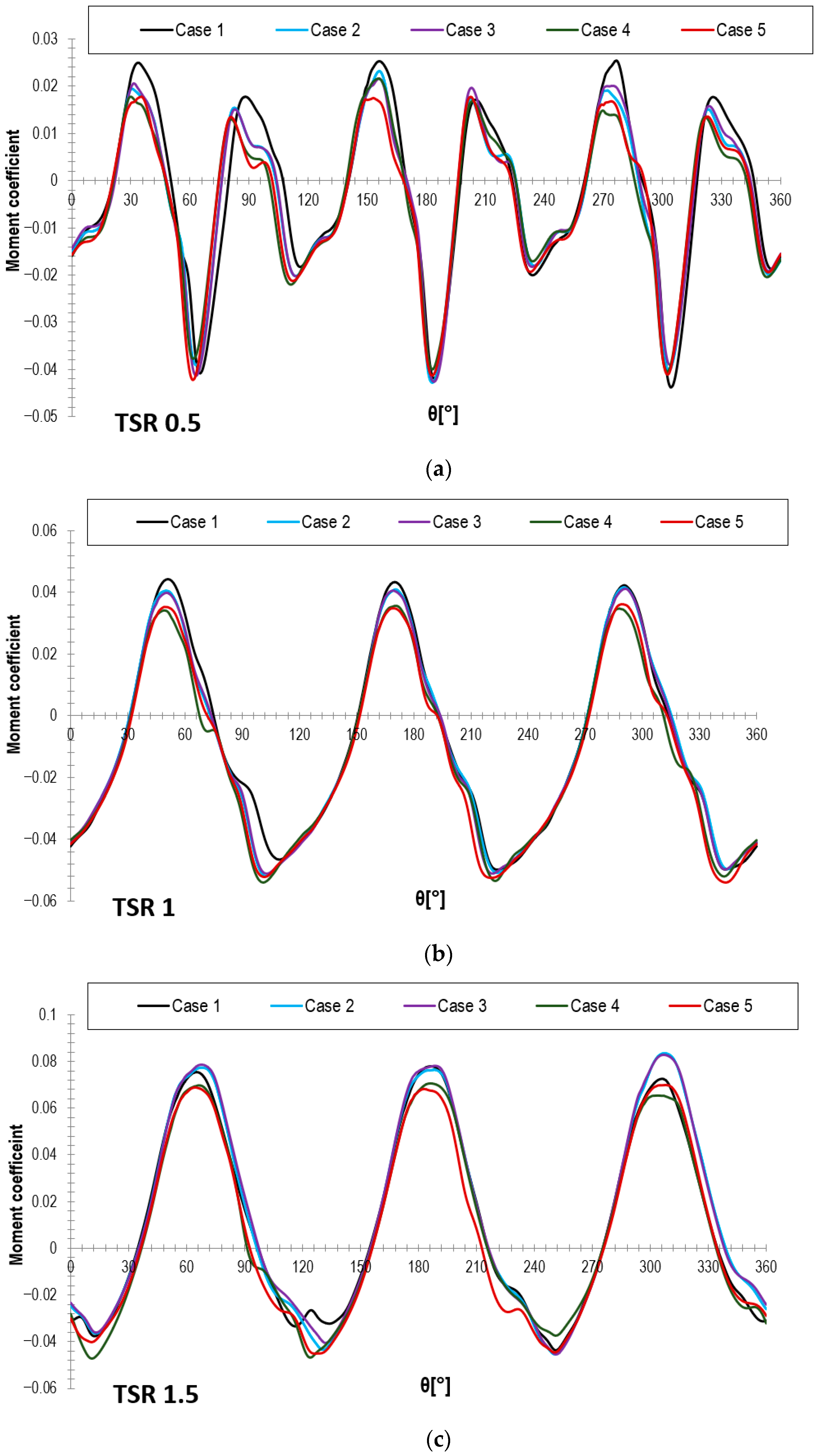
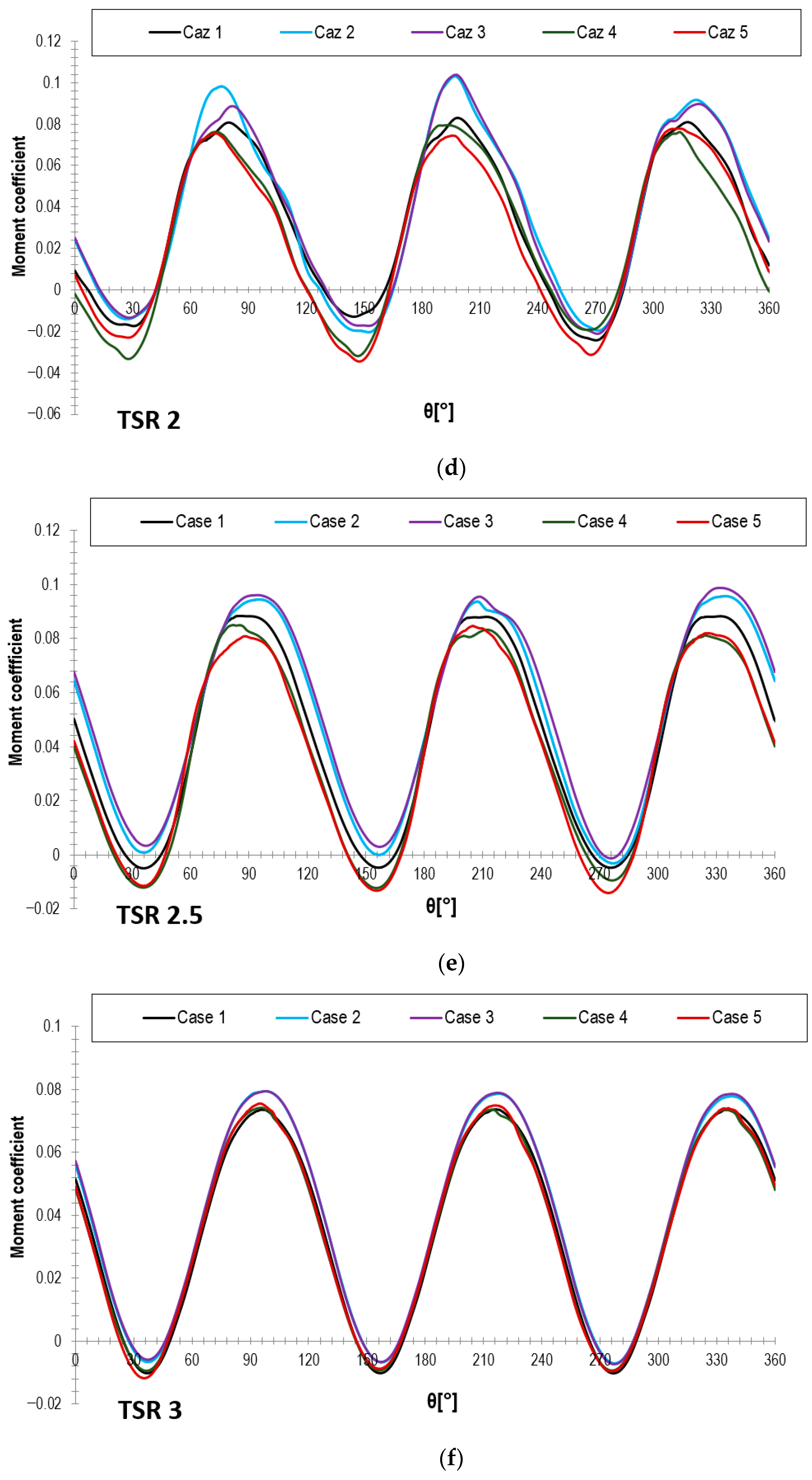
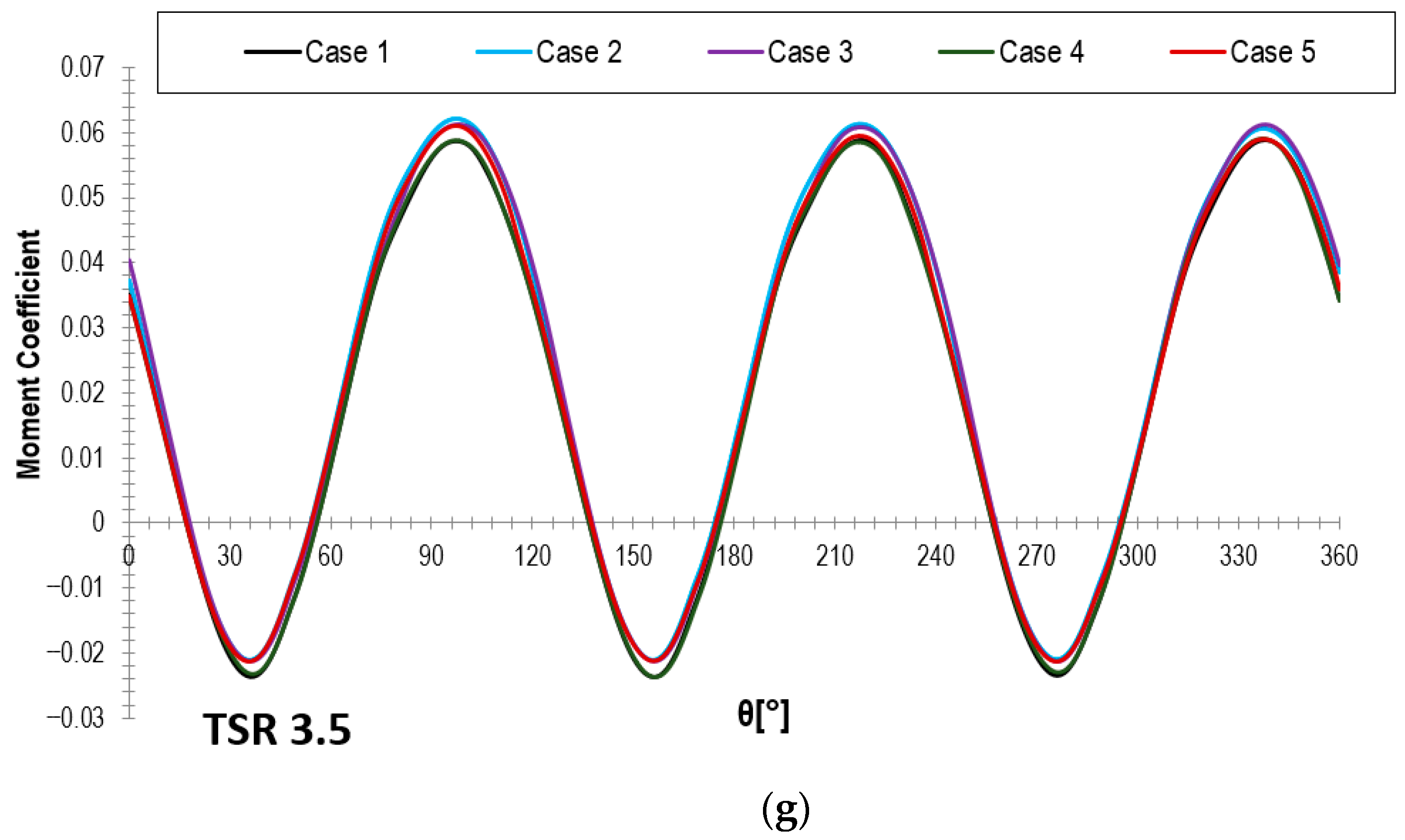
The moment coefficient variation for one full revolution is given in
Figure 16 for various values of the TSR.
A consistent ranking emerged from the comparative moment curves. For TSRs above 1, Case 3 was identified as the most favorable solution, while the two configurations perforated over the downstream two thirds of the extrados (Cases 2 and 3) outperformed the baseline rotor. In contrast, the two configurations modified only over the final third of the chord (Cases 4 and 5) registered lower values for the moment coefficient compared to the baseline. This pattern was reported as most evident at TSR = 2.5, where the aerodynamic benefit of the more upstream perforation placement became most pronounced.
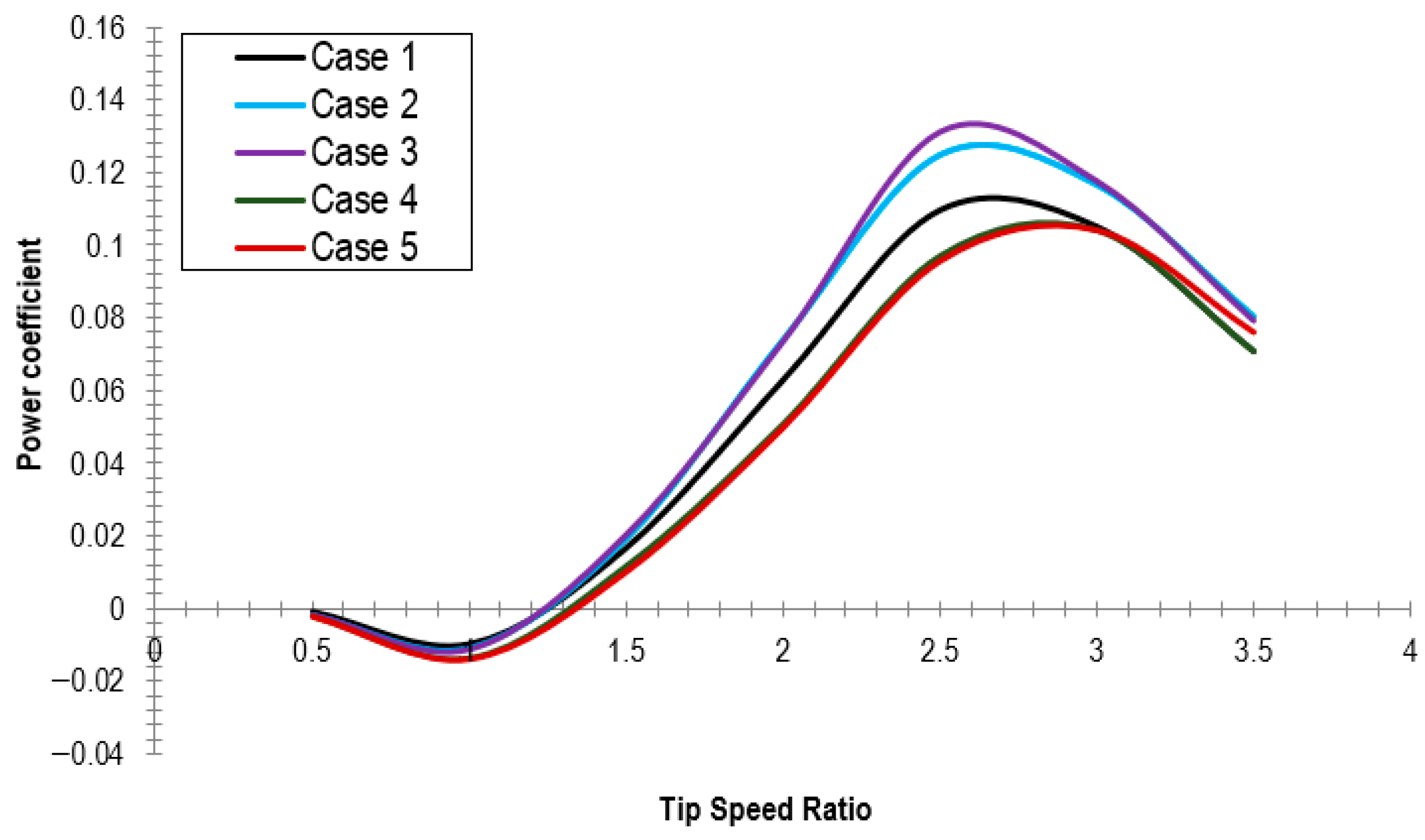
The power coefficient curves confirmed the ranking obtained from the moment coefficient analysis. For the baseline turbine, the highest computed power coefficient was 0.109 at TSR = 2.5, corresponding to a power output of 6.869 W. Case 2 improved this performance to c
p = 0.125 and 7.846 W at the same TSR, while case 3 achieved the best overall result, with c
p = 0.131 and 8.249 W. In comparison, cases 4 and 5 yielded lower peak values than the baseline, namely power coefficients of 0.097 and 0.095, corresponding to 6.102 W and 5.997 W, respectively. The power coefficient variation with tip speed ratio is illustrated in
Figure 17. This characteristic curve was constructed from the revolution averaged moment coefficient obtained from the transient CFD simulations for TSR values between 0.5 and 3.5. These differences correspond to an improvement of approximately 20% in aerodynamic performance at the best operating point and constitute the clearest quantitative evidence of the benefit associated with the selected perforation layout.
The comparative power and moment characteristics also showed that the favorable response is not simply associated with the presence of perforations, but rather with their specific distribution along the extrados. The downstream two thirds configurations consistently outperformed the final third configurations, which indicates that the aerodynamic benefit is strongly governed by the chordwise location of the passive flow control method.
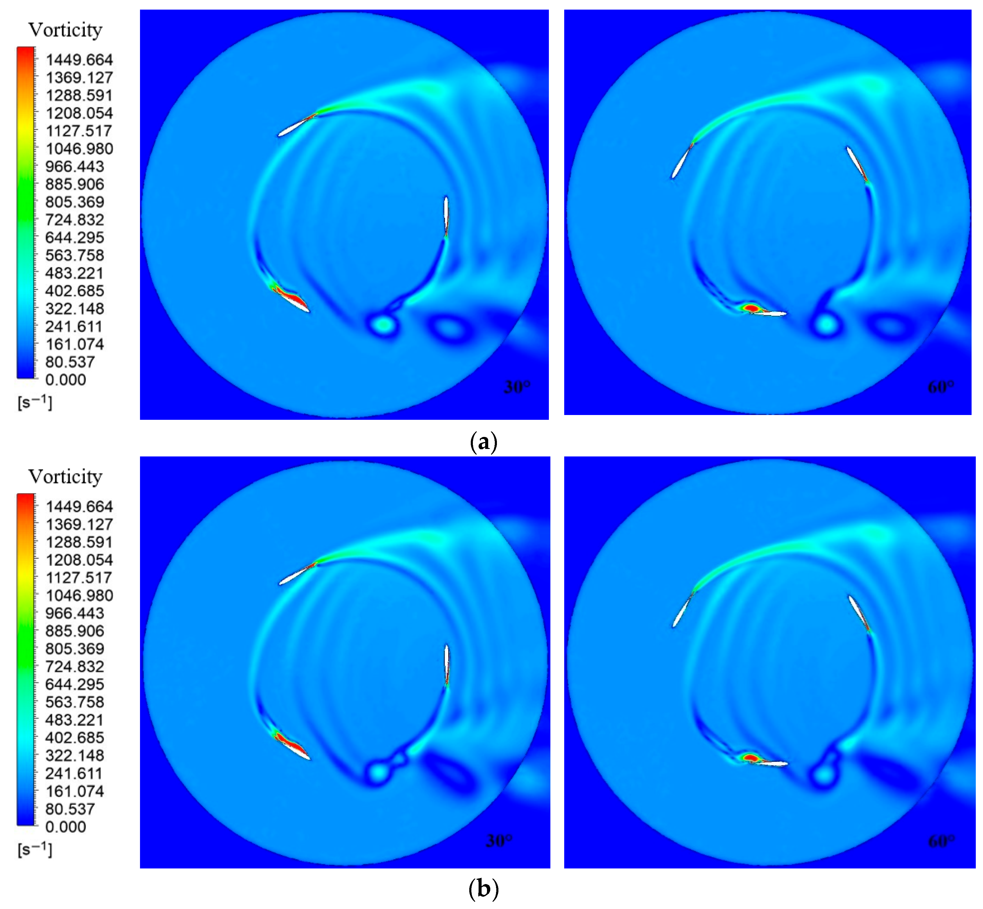
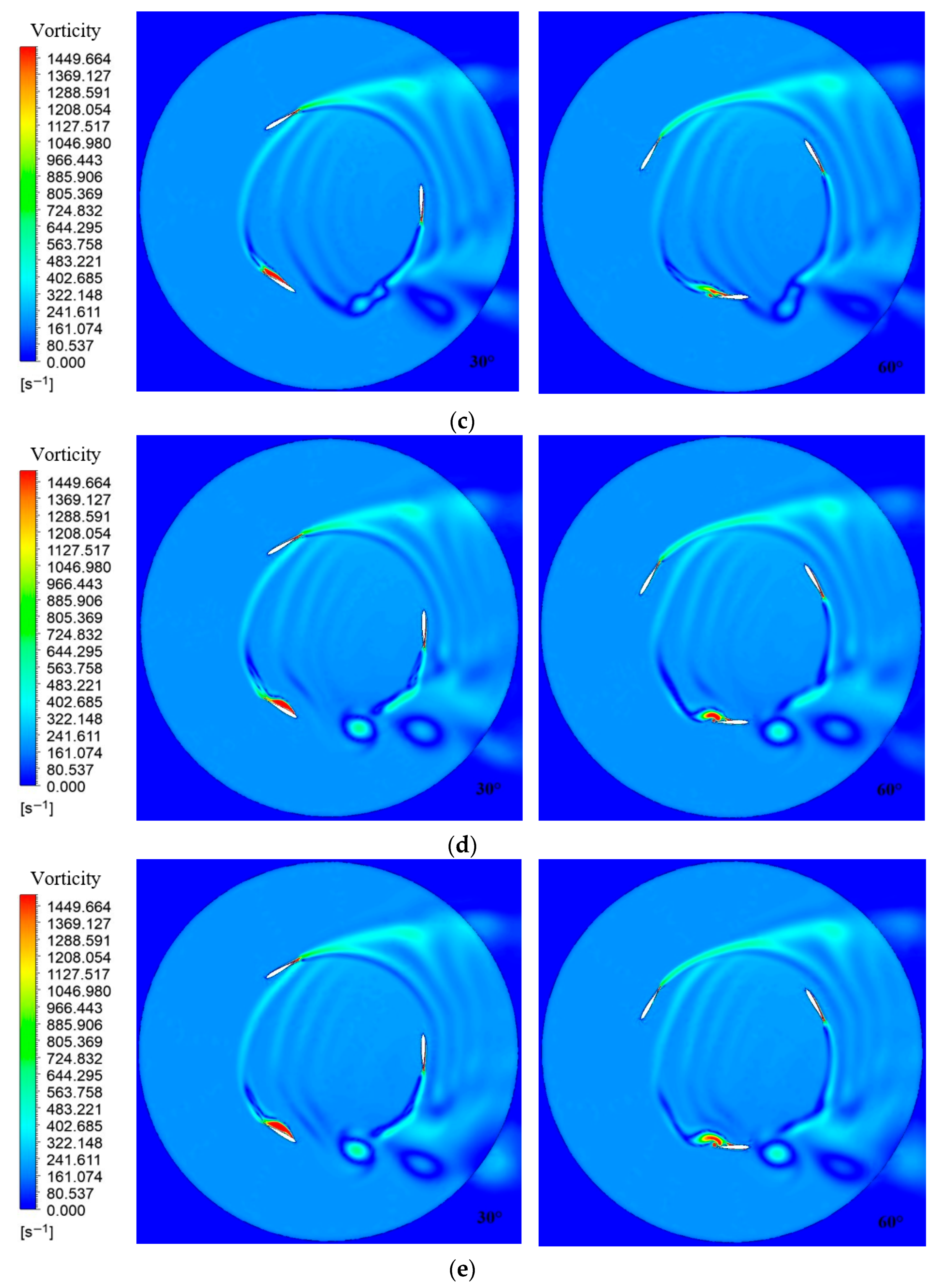
The rotor level vorticity fields provide a physical explanation for the observed performance trends. At TSR = 2.5, where the highest power coefficients were recorded for Cases 1-3, the perforated configurations were reported to promote the breakup and dissipation of the vortical structures generated by the blades. In the baseline case, these vortices persisted longer and dissipated close to the leading edge of the following blade, thereby acting as an aerodynamic brake on the downstream blade. In the perforated configurations, particularly for the cases perforated over the downstream two thirds of the extrados, the earlier dissipation of vortices weakened this adverse blade–wake interaction. The vorticity fields for all studied cases at 2.5 tip speed ratio are given in
Figure 18. The plotted quantity is the 2D vorticity, Equation (3), computed in ANSYS 19.2 Fluent from the resolved velocity field and used here to visualize the wake structures and their interaction with the following blade.
This interpretation is consistent with the airfoil results. The downstream two thirds perforation layout delayed boundary layer separation in the isolated profile simulations, whereas the final third layout was reported to be less effective because separation begins to develop earlier along the chord. As a result, limiting the perforations to the final third of the profile does not provide sufficient control authority to alter the onset of separation in a meaningful way, which explains why Cases 4 and 5 underperformed not only Cases 2 and 3, but also the baseline rotor.
Taken together, the numerical results establish a clear hierarchy among the investigated blade concepts. All perforated airfoils improved sectional lift relative to the baseline profile, but only the configurations perforated over the downstream two thirds of the extrados translated this advantage into superior rotor level performance. Within this subgroup, Case 3, characterized by smaller and denser perforations, provided the most favorable overall balance between aerodynamic improvement and efficiency. The final third configurations, despite incorporating the same passive control method, were less effective because their placement did not adequately delay separation and therefore did not improve the rotor’s mean moment and power characteristics.
With respect to low TSR behavior, the reports indicate that Cases 2 and 3 may be associated with improved start-up related performance when the mean coefficients are examined over complete revolutions. However, the comparative instantaneous moment plots at TSR = 0.5 and 1 also showed local maxima for the baseline model. Accordingly, the present numerical evidence supports a robust conclusion regarding nominal and supra-unitary operating performance, while any claim regarding self-starting improvement should be interpreted more cautiously pending dedicated experimental or full 3D validation.
4. Discussion
The present results support the working hypothesis that inclined perforations placed on the extrados of a symmetric NACA0012 blade can improve the aerodynamic behavior of a straight-bladed VAWT when their geometry and chordwise location are properly selected. Although all perforated profiles enhanced lift relative to the baseline airfoil, the turbine-level response showed that the aerodynamic benefit was strongly configuration dependent. In particular, the configuration with smaller and denser perforations distributed over the downstream two thirds of the extrados provided the most favorable compromise between geometry improvement and rotor performance, indicating that passive control effectiveness depends not only on the presence of surface modifications, but also on their precise placement and scale. This observation is consistent with the original objective of the study, namely, to improve aerodynamic performance while preserving a geometrically simple blade concept.
The baseline numerical response is consistent with representative straight-bladed VAWT results reported in relevant literature. Classical wind-tunnel data shared in [
26] for Darrieus rotors with NACA0012 blades showed the characteristic dependence of the power coefficient on tip speed ratio, with a clearly identifiable optimum operating region. A similar trend for c
P-TSR dependency behavior was also reported in the small-scale wind tunnel and unsteady CFD study of Howell et al. [
27] and in the field and wind tunnel straight-bladed VAWT measurements of Li et al. [
28]. From a methodological perspective, the present rotor level setup is also consistent with later numerical studies such as [
29], who analyzed a three-bladed H-Darrieus rotor using 2D CFD simulations with the k–ω SST model. In addition, Lanzafame et al. [
30] developed and experimentally validated a 2D CFD model for a small NACA0012 H-Darrieus rotor, showing that small rotor VAWT CFDs can reproduce experimental trends when supported by appropriate sensitivity analysis. In this context, the baseline rotor considered here exhibits the expected aerodynamic behavior of a straight-bladed Darrieus turbine, namely a similar trend for the power coefficient curve with a distinct optimum value in the low to moderate TSR range. Therefore, while the present model should still be interpreted as a 2D comparative aerodynamic screening tool rather than a fully validated predictor of absolute performance, the agreement in overall trend with classical and modern literature supports the physical consistency of the adopted numerical framework.
The findings of this numerical analysis are in line with previous studies showing that passive flow control devices can improve the performance of straight-bladed VAWTs by delaying separation, modifying the local pressure field, and reducing adverse blade–wake interactions [
13,
14,
15,
16,
17,
18,
19]. At the same time, the present results also confirm a recurrent conclusion in the literature: passive control strategies are highly sensitive to geometric configuration and operating regime. The poorer behavior of Cases 4 and 5 demonstrates that the same underlying concept may become ineffective when applied too far downstream, where the onset of separation is already developing. In this respect, the present study extends previous work [
24,
25] by showing that inclined extrados perforations can function as an effective passive control strategy only when positioned sufficiently upstream to influence the separation process in a meaningful way.
An important implication of the present results concerns the trade-off between improved low-speed behavior and nominal operating efficiency, which remains a central issue in Darrieus-type turbines [
20,
21]. The numerical results clearly support the benefit of the proposed concept under nominal operating conditions, with the best performing configuration producing the highest mean moment and power coefficients and an approximately 20% increase in power output at the optimal TSR. However, although the results suggest that the modified blades may also improve low-TSR behavior, the current evidence is not sufficient to claim a definitive enhancement of self-starting capability. Accordingly, the main contribution of the present study lies in demonstrating a robust improvement in aerodynamic efficiency, while the start-up implications should be regarded as promising but still preliminary.
From a broader renewable energy perspective, these findings are relevant because small VAWTs are increasingly considered for urban and decentralized energy applications, where compactness, omnidirectional operation, and low system complexity are important design requirements. In this context, a passive blade modification capable of improving rotor efficiency without introducing additional actuation or control requirements is of practical interest. Nevertheless, the study remains limited by its 2D numerical framework and should therefore be interpreted as a comparative design screening investigation rather than a final validation of the concept. Future work should include experimental verification, 3D CFD analysis, and a more extensive parametric optimization of perforation angle, depth, spacing, and spanwise distribution, since the present 45° inclination was adopted as a proof-of-concept choice rather than an optimized design variable. Because the present work was limited to aerodynamic CFD screening, no structural stress, fatigue, or durability analysis of the perforated blade was performed. These aspects should be addressed in future 3D structural or fluid–structure interaction investigations.
5. Conclusions
This study demonstrated that 45° inclined extrados perforations can improve the aerodynamic performance of a straight-bladed VAWT when their geometry and chordwise placement are appropriately selected. Among the investigated configurations, the blade with smaller and denser perforations distributed over the downstream two thirds of the extrados provided the best overall performance at both airfoil and rotor level.
The numerical results showed that this configuration increased the mean moment and power coefficients relative to the baseline NACA0012 rotor, reaching an approximately 20% improvement in power at the optimum operating condition. The observed benefit was associated with delayed flow separation and reduced adverse wake interaction between successive blades.
Overall, the proposed perforated blade concept represents a promising low complexity passive strategy for enhancing the aerodynamic efficiency of small straight-bladed VAWTs. Nevertheless, the conclusions are based on 2D CFDs and should be confirmed through experimental validation and 3D numerical analysis.